JP3875186B2 - Fixing device - Google Patents
Fixing device Download PDFInfo
- Publication number
- JP3875186B2 JP3875186B2 JP2002361874A JP2002361874A JP3875186B2 JP 3875186 B2 JP3875186 B2 JP 3875186B2 JP 2002361874 A JP2002361874 A JP 2002361874A JP 2002361874 A JP2002361874 A JP 2002361874A JP 3875186 B2 JP3875186 B2 JP 3875186B2
- Authority
- JP
- Japan
- Prior art keywords
- peeling
- finger piece
- fixing roll
- mounting portion
- roll
- Prior art date
- Legal status (The legal status is an assumption and is not a legal conclusion. Google has not performed a legal analysis and makes no representation as to the accuracy of the status listed.)
- Expired - Fee Related
Links
Images


Classifications
-
- G—PHYSICS
- G03—PHOTOGRAPHY; CINEMATOGRAPHY; ANALOGOUS TECHNIQUES USING WAVES OTHER THAN OPTICAL WAVES; ELECTROGRAPHY; HOLOGRAPHY
- G03G—ELECTROGRAPHY; ELECTROPHOTOGRAPHY; MAGNETOGRAPHY
- G03G15/00—Apparatus for electrographic processes using a charge pattern
- G03G15/20—Apparatus for electrographic processes using a charge pattern for fixing, e.g. by using heat
- G03G15/2003—Apparatus for electrographic processes using a charge pattern for fixing, e.g. by using heat using heat
- G03G15/2014—Apparatus for electrographic processes using a charge pattern for fixing, e.g. by using heat using heat using contact heat
- G03G15/2017—Structural details of the fixing unit in general, e.g. cooling means, heat shielding means
- G03G15/2028—Structural details of the fixing unit in general, e.g. cooling means, heat shielding means with means for handling the copy material in the fixing nip, e.g. introduction guides, stripping means
Landscapes
- Physics & Mathematics (AREA)
- General Physics & Mathematics (AREA)
- Fixing For Electrophotography (AREA)
- Separation, Sorting, Adjustment, Or Bending Of Sheets To Be Conveyed (AREA)
- Paper Feeding For Electrophotography (AREA)
Description
【0001】
【発明の属する技術分野】
本発明は、電子写真方式のプリンタ用などの定着装置に用いられる剥離用指片及びそれに関連する取付け部に関する。
【0002】
【従来の技術】
今日広く用いられるゼログラフィ即ち電子写真方式のプリンタにおいては、電荷保持部材が均一の電位に帯電され、その後で、複写されるべきオリジナルの光画像に露光される。この露光は、露光された領域即ち背景領域の電荷保持表面を放電させ、オリジナル内に含まれる画像領域に対応する静電潜像を部材上に生成する。続いて、電荷保持表面上の静電潜像は、当分野においてトナーと呼ばれる現像粉末で画像を現像することによって可視化される。現像システムのほとんどは、帯電キャリア粒子とキャリア粒子に摩擦帯電によって付着する帯電トナー粒子の両者からなる現像材を採用している。現像中に、トナー粒子は、キャリア粒子から電荷保持領域上の画像領域の帯電パターンによって吸引されて、光導電性領域上に粉末画像を形成する。この画像は次に、複写紙などの用紙に転写され、加熱によって又は圧力を加えることによって、その用紙に永久定着される。トナー画像の用紙への転写に引続き、次の画像形成サイクルに備えて、電荷保持部材は、その上に残る残留トナーが除去される。
【0003】
トナー画像を定着することへの取組みの1つは、少なくとも一方が内部で加熱される1対の対向ローラ部材間に未定着のトナー画像を含む用紙を通過させて熱及び圧力を加えることである。この工程の間に、トナー材の温度は、トナー材が融着し粘着性になる温度にまで高められる。この加熱によって、トナーがある程度まで用紙の繊維又は気孔内に流れ込む。その後トナー材が冷えるのに伴って、トナー材の固化によって該用紙にトナー材が定着することになる。こうした定着装置の典型は、定着ロールがシリコンゴムその他低界面エネルギーのエストラマーのような粘着性材料で被覆された2ロールシステムである。
【0004】
定着ロール表面として低界面エネルギー物質を用いているにも関わらず、定着処理の間に、印刷基材は、定着ロールと加圧ロールの間のニップを通過した後に定着ロールに貼りついたままになる傾向がある。こうしたことが起こると、貼りついた印刷基材は通常の印刷基材経路に従わないで、定着ロールの周りの弧状経路に留まり続け、最終的には紙詰まりを生じ、次の画像形成サイクルを行い得るようにするのに先立って、オペレータが介入して詰まった紙を取除くことが必要になる。その結果、印刷基材が定着ニップの下流側において定着ロールから確実に剥がされるようにすることが、慣用的になってきた。取組みの1つは、定着ロールに接触して配置された複数の剥離用指片を用いて定着ロールから印刷基材を剥がすことである。これは、多くの点において満足であるが、定着ロールの寿命と印刷の品質の両面に関して問題をもたらす。許容できる水準の剥離を保証するためには、定着ロールに当る剥離用指片に、シリコンゴムを定着ロールから剥がしてしまいがちな力及び迎え角で荷重をかけることがしばしば必要になり、そのことによって定着装置としての機能をもはや果たすことができない程度にまで、該ロールに損傷を与えてしまうことになる。
【0005】
【特許文献1】
米国特許第4,062,534号
【特許文献2】
米国特許第5,448,347号
【特許文献3】
米国特許第6,028,039号
【0006】
【発明が解決しようとする課題】
本発明は、剥離用指片及び関連する取付け構造の改良された設計に向けられたものである。
【0007】
米国特許第4,062,534号には、剥離用剛性爪の複数が定着ロールに当るように付勢された定着装置が開示される。爪の各々について、スプリングがロールに当るように爪を直接付勢する。
【0008】
米国特許第5,448,347号には、定着ロールから用紙を剥離するのに用いられるスカイブのための取付け構成が開示される。スカイブは、可撓性の取付け部上に取付けられ、さらに剥離された用紙を定着装置の後の経路に沿うように向ける案内表面を定める。
【0009】
米国特許第6,028,039号には引込み式のスカイブ(skive:削り出し)組立体が開示される。剛性スカイブの各々は、定着ロールの表面に対してスプリングによって付勢される。スカイブ及びスプリングは、紙詰まりを手動で除去するためにロールからスカイブを外すための引込み装置上に取付けられる。
【0010】
公知技術においては、可撓性の剥離用指片を機械内に固く取付け、その指片を専ら指片の変形がもたらすスプリング力によってのみ、定着ロールに当るように付勢している。
【0011】
【課題を解決するための手段】
本発明の1つの態様によると、定着ロールと、第1の剥離用指片取付け部と、第1の剥離用指片取付け部を実質上定着ロールに向けて停止部に当るように付勢するためのスプリング手段と、第1の剥離用指片取付け部に取付けられ、第1の剥離用指片取付け部が停止部に対して付勢されたときにスプリング力で定着ロールに接触する第1の剥離用指片を含む、印刷に有用な定着装置が提供される。
【0012】
【発明の実施の形態】
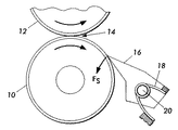
図1は、公知技術において知られた剥離用指片組立体の側面図であり、それ自体では、一般的設計において、上記で引用された米国特許第4,062,534号及び米国特許第5,822,668号に示された剥離用指片と同様のものである。定着ロール10は、電子写真方式のいずれの定着装置においても典型的なものであり、その長手方向に沿って加圧ロール12に接触し、間にニップ14を形成する。電子写真印刷によって生成されるもののような当分野において良く知られた印刷用紙は、ロール10、12の回転によってニップを通って引出される。具体的には、図1において下向きになっている印刷用紙上に定着したばかりのトナーのようなマーキング材が、用紙をニップ14の通過後にも定着ロール10の表面に貼りついた状態にすることがある。用紙がニップ14を通って引出されたときに定着ロール10の表面から剥がされるためには、1つ又はそれ以上の剥離用指片16のようなスプリング利用により付勢された剥離用指片を用いるのが通常である。剥離用指片16の各々は、ニップ14の近傍で定着ロール10に接触しており、用紙がその上を通るときに該用紙をロール10から持ち上げるように機能する。
【0013】
図1に示された公知技術の具体例によると、剥離用指片16は、それ自体が本来ばね定数を持たない、実質的に剛性の部材である。ロール10に対して剥離用指片16を付勢するスプリング力Fsは、専らスプリング18(図示のものはトーション・スプリング形式のものであるが、同様なその他の形式のものであってもよい)によってのみ与えられる。そのため剥離用指片16は、軸20上に回転可能に取付けられる。
【0014】
Fs値の選択は、基本的にはスプリング18に関連するばね定数に関係するものであるが、性能を充足するためには、少なくとも2つの競合する利害を均衡させる必要がある。極めて当たり前のことであるが、力Fsが強力であればあるほど、ロール10の表面から貼りついた用紙を剥がすことにおいて効果的である。しかしながら、力Fsが強力でありすぎれば、ロール10の表面に損傷を与えることになり好ましくない。そのためFs値の選択は、ロール10の変形に、従って材料選択にも密接に関係することになる。また、剥離用指片16の周りに紙詰まりが生じた場合には、力Fsが小さければ小さいほど、ロール10から剥離用指片16を離して軸20の周りに回転させるようにする際に効果的である。効率的剥離のための最適Fsは、多くの場合、紙詰まり除去及び防止のためのFs値とは矛盾する。
【0015】
図2は、本発明による剥離用指片組立体の実施形態の側面図である。その実施形態では、軸20上に取付けられた単一の剥離用剛性指片を有する代わりに、ここでは「取付け部」32と呼ばれるものに剥離用指片30が結合されていることにおいて、上記公知の技術例とは異なる。この実施形態における剥離用指片30は変形可能な部材であり、典型的には、実質的にステンレス鋼製であり、ロール10に接触して配置され、したがって僅かに変形されたときに力FFを生成するばね定数を有する。次に、取付け部32は、軸20に回転可能に取付けられ、具体的には、図1の剥離用剛性指片の場合と殆ど同様に、(この場合には)捩りばね18によってロール10にかかる力FMで付勢される。しかしながら、取付け部32は、ロール10に当るようにではなく、停止部34(ここで、「停止部」は利用可能などのような拘束表面でもよい)に当るように付勢される。そのため、図示された実施形態において、ロール10に対する唯一の力は、剥離用指片30の変形によって与えられる力FFであり、スプリング18によって与えられる力FMは究極的に停止部34によって停止される。
【0016】
図5は、図2に示す剥離用指片30及び関連する取付け部32を複数含む組立体の斜視図である。1つの実施形態において、ロール10に沿ったこうした複数の取付け部32の各々は互いに独立に移動自在である。見て分るように、各取付け部32のいずれかの側に(又は、より広義には各取付け部に隣接して)、ここでは40で示され「バッフル」と呼ばれるものが更に設けられる。下記で説明されるように、バッフル40は、剥取りを失敗した用紙が皺にされる表面を提供するものである。
【0017】
図2の構成は、このように図1の実施例に比べてより大きな設計裁量の余地を与えることができる。FF値は、剥離効率の目的に則って選択することができ、FM値は、紙詰まりの除去及び剥離用指片30の保護を目的とする選択をすることができる。図3は、剥離用指片30によってロール10から剥離されずに、用紙Sの前縁が剥離用指片30の下を通り、そのためバッフル40と取付け部32の下部とで皺にされてしまう最悪のシナリオ即ち剥離不良における図2の構成の挙動を示す。用紙が取付け部32とバッフル40とで皺にされることによって、取付け部32がロール10から押離されることになり、用紙Sが皺になることができる「皺発生ゾーン」の空間を与えるが、小容積内での皺寄せ圧縮によって用紙周辺のハードウェアが損傷を受けることになりがちである。取付け部32が移動して遠ざかることは、損傷を受ける可能性のある皺寄せゾーンから剥離用指片30離れさせることになる。取付け部32はまた、ここでは特別に湾曲された表面36である、剥離失敗の用紙を案内するように設計された外形表面を定めることができ、取付け部32の下部において用紙に皺が発生したとき、それが取付け部32を押し離すようになる。
【0018】
図4は、本発明の1つの実施形態の更なる可能性を示しており、それは、取付け部32の各々が、軸20の周りを、停止部34に当る位置に対する相対的角度で90度又はそれ以上の大きな角度を回転することができるようにしたものである。図示のように、剥離失敗シートSが取付け部32を広い回転角度で回転するように押す。剥離用指片30は、バッフル40の上面より下に位置するので、バッフル40によって皺になった用紙との接触から事実上隠されるすなわち接触しなくなる。
【0019】
本発明は、開示された構造を参照して説明してきたが、記載された詳細に限定されることなく、添付した特許請求の範囲の記載に包含されるような修正及び変更をも含むことが意図される。
【図面の簡単な説明】
【図1】定着ロールと相互作用する公知技術による剥離用指片の側面図である。
【図2】本発明による剥離用指片とそれに関連する取付け部を定着ロールに対して特定の位置で示す側面図である。
【図3】本発明による剥離用指片とそれに関連する取付け部を定着ロールに対して別の特定の位置で示す側面図である。
【図4】本発明による剥離用指片とそれに関連する取付け部を定着ロールに対してさらに別の特定の位置で示す側面図である。
【図5】本発明による剥離用指片の組立体の斜視図である。
【符号の説明】
10 定着ロール
12 加圧ロール
18 トーション・スプリング
20 軸
30 剥離用指片
32 取付け部
34 停止部
40 バッフル[0001]
BACKGROUND OF THE INVENTION
The present invention relates to a peeling finger piece used in a fixing device for an electrophotographic printer or the like and a mounting portion related thereto.
[0002]
[Prior art]
In xerographic or electrophotographic printers widely used today, the charge holding member is charged to a uniform potential and then exposed to the original light image to be copied. This exposure discharges the charge-carrying surface of the exposed or background area, producing an electrostatic latent image on the member that corresponds to the image area contained within the original. Subsequently, the electrostatic latent image on the charge retentive surface is visualized by developing the image with a developing powder called toner in the art. Most development systems employ a developer comprising both charged carrier particles and charged toner particles that adhere to the carrier particles by frictional charging. During development, the toner particles are attracted from the carrier particles by the charge pattern of the image area on the charge retention area to form a powder image on the photoconductive area. This image is then transferred to a sheet of paper such as a copy sheet and permanently fixed to the sheet by heating or by applying pressure. Subsequent to the transfer of the toner image onto the paper, the residual toner remaining on the charge holding member is removed in preparation for the next image forming cycle.
[0003]
One approach to fixing a toner image is to apply heat and pressure by passing a sheet containing an unfixed toner image between a pair of opposing roller members, at least one of which is internally heated. . During this process, the temperature of the toner material is raised to a temperature at which the toner material becomes fused and tacky. This heating causes the toner to flow into the paper fibers or pores to some extent. Thereafter, as the toner material cools, the toner material is fixed to the paper by the solidification of the toner material. Typical of such fusers is a two-roll system in which the fuser roll is coated with an adhesive material such as silicone rubber or other low interface energy elastomer.
[0004]
Despite the use of low interfacial energy materials as the fuser roll surface, during the fusing process, the printing substrate remains attached to the fuser roll after passing through the nip between the fuser roll and the pressure roll. Tend to be. When this happens, the stuck print substrate will not follow the normal print substrate path and will remain in the arc path around the fuser roll, eventually resulting in a paper jam and the next imaging cycle. Prior to being able to do so, it is necessary for the operator to intervene to remove the jammed paper. As a result, it has become conventional to ensure that the printing substrate is peeled off the fixing roll downstream of the fixing nip. One approach is to peel the print substrate from the fixing roll using a plurality of peeling fingers placed in contact with the fixing roll. This is satisfactory in many respects, but presents problems with respect to both fuser roll life and print quality. In order to guarantee an acceptable level of release, it is often necessary to apply a load to the release finger that strikes the fuser roll with a force and angle of attack that tends to peel the silicone rubber off the fuser roll. This damages the roll to such an extent that it can no longer function as a fixing device.
[0005]
[Patent Document 1]
US Pat. No. 4,062,534 [Patent Document 2]
US Pat. No. 5,448,347 [Patent Document 3]
US Pat. No. 6,028,039 [0006]
[Problems to be solved by the invention]
The present invention is directed to an improved design of the release finger and associated mounting structure.
[0007]
U.S. Pat. No. 4,062,534 discloses a fixing device in which a plurality of peeling rigid claws are biased so as to hit a fixing roll. For each nail, the nail is directly biased so that the spring hits the roll.
[0008]
U.S. Pat. No. 5,448,347 discloses a mounting arrangement for a skive used to peel a sheet from a fuser roll. The skive is mounted on a flexible mounting and defines a guide surface that directs the peeled sheet along a path behind the fuser.
[0009]
U.S. Pat. No. 6,028,039 discloses a retractable skive assembly. Each of the rigid skives is biased by a spring against the surface of the fuser roll. The skive and spring are mounted on a retraction device for removing the skive from the roll to manually remove the jam.
[0010]
In the known technique, a flexible peeling finger piece is firmly attached in the machine, and the finger piece is urged to hit the fixing roll only by a spring force caused by the deformation of the finger piece.
[0011]
[Means for Solving the Problems]
According to one aspect of the present invention, the fixing roll, the first peeling finger piece mounting portion, and the first peeling finger piece mounting portion are biased substantially toward the fixing roll so as to hit the stop portion. And a first spring member that contacts the fixing roll with a spring force when the first peeling finger piece mounting portion is biased against the stop portion. A fixing device useful for printing is provided, including a stripping finger.
[0012]
DETAILED DESCRIPTION OF THE INVENTION
FIG. 1 is a side view of an exfoliating finger assembly known in the prior art, as such, in general design, U.S. Pat. No. 4,062,534 and U.S. Pat. No. 5, cited above. , 822, 668, similar to the peeling finger piece. The fixing
[0013]
According to a specific example of the known technique shown in FIG. 1, the peeling
[0014]
The selection of the Fs value is basically related to the spring constant associated with the
[0015]
FIG. 2 is a side view of an embodiment of a peel finger assembly according to the present invention. In that embodiment, instead of having a single stripping rigid finger mounted on the
[0016]
FIG. 5 is a perspective view of an assembly including a plurality of peeling
[0017]
The configuration of FIG. 2 can thus provide a larger room for design discretion as compared to the embodiment of FIG. The F F value can be selected according to the purpose of the peeling efficiency, and the F M value can be selected for the purpose of removing the paper jam and protecting the peeling
[0018]
FIG. 4 illustrates a further possibility of one embodiment of the present invention, which is that each of the
[0019]
The present invention has been described with reference to the disclosed structure, but is not limited to the details described, but may also include modifications and alterations as encompassed by the appended claims. Intended.
[Brief description of the drawings]
FIG. 1 is a side view of a peeling finger piece according to a known technique that interacts with a fixing roll.
FIG. 2 is a side view showing a peeling finger piece according to the present invention and a mounting portion related thereto at a specific position with respect to a fixing roll.
FIG. 3 is a side view showing the peeling finger piece according to the present invention and the attachment portion related thereto at another specific position with respect to the fixing roll.
FIG. 4 is a side view showing the peeling finger piece and the mounting portion related to the peeling finger piece according to the present invention at still another specific position with respect to the fixing roll.
FIG. 5 is a perspective view of an assembly of peeling finger pieces according to the present invention.
[Explanation of symbols]
DESCRIPTION OF
Claims (4)
定着ロールと、
剥離用指片取付け部と、
前記剥離用指片取付け部を実質上前記定着ロールに向けて停止部に当るように付勢するためのスプリング手段と、
前記剥離用指片取付け部に取付けられ、前記剥離用指片取付け部が前記停止部に当るように付勢されたときにスプリング力で前記定着ロールに接触する剥離用指片と、
前記剥離用指片が前記定着ロールに接触しているときに該剥離用指片に隣接する表面を該定着ロールの長手方向に沿って定めるバッフルとを備え、
前記バッフルは、前記定着ロールと前記剥離用指片取付け部の間で皺になった用紙が前記剥離用指片取付け部を前記定着ロールから離れる方向に動かすのを助けるものであり、
前記剥離用指片取付け部は、前記剥離用指片が前記バッフルによって隠される位置に回転可能になっており、該剥離用指片取付け部は、前記定着ロールと該剥離用指片取付け部の間で皺になった用紙が該剥離用指片取付け部を前記剥離用指片が前記バッフルによって隠される前記位置に回転するのを助ける湾曲表面を有し、前記定着ロールと前記剥離用指片取付け部の間で皺になった用紙が前記バッフルによって前記定着ロールから離れるように案内される、
ことを特徴とする定着装置。A fixing device useful for printing,
A fixing roll;
A peeling finger mounting part;
Spring means for urging the peeling finger piece mounting portion substantially toward the fixing roll so as to hit the stop portion;
A peeling finger piece that is attached to the peeling finger piece mounting portion and comes into contact with the fixing roll with a spring force when the peeling finger piece mounting portion is urged so as to hit the stop portion;
Wherein the surface adjacent to the peeling fingers when peeling fingers is in contact with the fixing roll in the longitudinal direction of the fixing roll and a constant Mel baffle,
The baffle state, and are an aid in paper wrinkled between the fixing roll and the peeling fingers mounting portion move away the peeling fingers mounting portion from the fixing roll,
The peeling finger piece mounting portion is rotatable to a position where the peeling finger piece is hidden by the baffle, and the peeling finger piece mounting portion includes the fixing roll and the peeling finger piece mounting portion. A sheet of paper that is wrinkled between has a curved surface that assists in rotating the peel finger attachment portion to the position where the peel finger is concealed by the baffle, and the fixing roll and the peel finger A sheet of paper that has become creased between the attachments is guided away from the fixing roll by the baffle;
A fixing device.
Applications Claiming Priority (2)
| Application Number | Priority Date | Filing Date | Title |
|---|---|---|---|
| US10/024195 | 2001-12-21 | ||
| US10/024,195 US6490428B1 (en) | 2001-12-21 | 2001-12-21 | Stripper fingers and associated mounts for a fuser in a printing apparatus |
Publications (3)
| Publication Number | Publication Date |
|---|---|
| JP2003223074A JP2003223074A (en) | 2003-08-08 |
| JP2003223074A5 JP2003223074A5 (en) | 2006-01-26 |
| JP3875186B2 true JP3875186B2 (en) | 2007-01-31 |
Family
ID=21819346
Family Applications (1)
| Application Number | Title | Priority Date | Filing Date |
|---|---|---|---|
| JP2002361874A Expired - Fee Related JP3875186B2 (en) | 2001-12-21 | 2002-12-13 | Fixing device |
Country Status (7)
| Country | Link |
|---|---|
| US (1) | US6490428B1 (en) |
| EP (1) | EP1333339B1 (en) |
| JP (1) | JP3875186B2 (en) |
| BR (1) | BR0205316A (en) |
| CA (1) | CA2414899C (en) |
| DE (1) | DE60212934T2 (en) |
| MX (1) | MXPA02012742A (en) |
Families Citing this family (15)
| Publication number | Priority date | Publication date | Assignee | Title |
|---|---|---|---|---|
| EP1341058B1 (en) * | 2002-03-01 | 2006-07-19 | Ricoh Company, Ltd | Fixing device with a peeler and image forming apparatus including the same |
| KR100433554B1 (en) * | 2002-07-23 | 2004-05-31 | 삼성전자주식회사 | Fixing device of printer |
| US6678496B1 (en) * | 2002-08-12 | 2004-01-13 | Nexpress Solutions Llc | Skive mechanism for reproduction apparatus fuser rollers |
| US6785503B2 (en) * | 2002-10-02 | 2004-08-31 | Xerox Corporation | Stripper fingers and roller assembly for a fuser in a printing apparatus |
| US7070182B2 (en) * | 2002-12-18 | 2006-07-04 | Ricoh Company, Limited | Sheet separating mechanism, fixing device, and image forming apparatus |
| US20050156377A1 (en) * | 2004-01-21 | 2005-07-21 | Xerox Corporation | Fuser sheet stripping system |
| US20060088346A1 (en) * | 2004-10-25 | 2006-04-27 | Xerox Corporation | Floating stripper finger assembly and a fuser having same |
| US20060182478A1 (en) * | 2005-02-15 | 2006-08-17 | Xerox Corporation | Stripper assembly and a printing machine including the same |
| US7310491B2 (en) * | 2005-09-23 | 2007-12-18 | Xerox Corporation | Non-gouging sheet stripper assembly |
| US7742732B2 (en) * | 2005-12-09 | 2010-06-22 | Xerox Corporation | Fuser arranged for reduced pressure member speed, and an image forming device including the same |
| US7280793B2 (en) | 2005-12-09 | 2007-10-09 | Xerox Corporation | Fuser arranged for braking and an image forming device including the same |
| US7505723B2 (en) | 2007-02-13 | 2009-03-17 | Xerox Corporation | Air knife system with pressure sensor |
| US7890037B2 (en) * | 2008-01-15 | 2011-02-15 | Xerox Corporation | Self adjusting metal stripper fingers |
| US8090282B2 (en) * | 2008-12-03 | 2012-01-03 | Xerox Corporation | Gain scheduling approach for fuser control to reduce inter-cycle time |
| DE102014006253A1 (en) * | 2014-04-28 | 2015-10-29 | Giesecke & Devrient Gmbh | stripping |
Family Cites Families (9)
| Publication number | Priority date | Publication date | Assignee | Title |
|---|---|---|---|---|
| JPS52101447U (en) | 1976-01-30 | 1977-08-01 | ||
| US4796880A (en) | 1986-12-29 | 1989-01-10 | Eastman Kodak Company | Skive with anti-gouge stiffener |
| US5160130A (en) * | 1991-11-25 | 1992-11-03 | Xerox Corporation | Thin-tip stripper finger for use with a fuser roll in an electrophotographic apparatus |
| US5448347A (en) | 1994-04-28 | 1995-09-05 | Eastman Kodak Company | Fuser skive mount |
| US5589925A (en) * | 1994-11-08 | 1996-12-31 | Eastman Kodak Company | Anti-gouging skive mechanism with replaceable fingers |
| US5532810A (en) * | 1994-11-08 | 1996-07-02 | Eastman Kodak Company | Fuser roller skive mechanism having anti-gouging skive fingers |
| US5623720A (en) * | 1996-09-30 | 1997-04-22 | Xerox Corporation | Method and apparatus for stripper bar rotation |
| US5822668A (en) | 1997-04-11 | 1998-10-13 | Xerox Coporation | Fuser subsystem module for an electrophotographic printer which pivots open for jam clearance |
| US6029039A (en) | 1998-11-20 | 2000-02-22 | Eastman Kodak Company | Retractable contact skive assembly for reproduction apparatus fuser rollers |
-
2001
- 2001-12-21 US US10/024,195 patent/US6490428B1/en not_active Expired - Lifetime
-
2002
- 2002-12-13 JP JP2002361874A patent/JP3875186B2/en not_active Expired - Fee Related
- 2002-12-17 BR BR0205316-0A patent/BR0205316A/en not_active Application Discontinuation
- 2002-12-18 MX MXPA02012742A patent/MXPA02012742A/en active IP Right Grant
- 2002-12-20 CA CA002414899A patent/CA2414899C/en not_active Expired - Fee Related
- 2002-12-20 EP EP02028636A patent/EP1333339B1/en not_active Expired - Fee Related
- 2002-12-20 DE DE60212934T patent/DE60212934T2/en not_active Expired - Lifetime
Also Published As
| Publication number | Publication date |
|---|---|
| EP1333339B1 (en) | 2006-07-05 |
| DE60212934T2 (en) | 2006-11-02 |
| BR0205316A (en) | 2004-07-20 |
| US6490428B1 (en) | 2002-12-03 |
| EP1333339A3 (en) | 2003-08-13 |
| EP1333339A2 (en) | 2003-08-06 |
| JP2003223074A (en) | 2003-08-08 |
| CA2414899C (en) | 2006-01-31 |
| CA2414899A1 (en) | 2003-06-21 |
| DE60212934D1 (en) | 2006-08-17 |
| MXPA02012742A (en) | 2005-08-26 |
Similar Documents
| Publication | Publication Date | Title |
|---|---|---|
| JP3875186B2 (en) | Fixing device | |
| JPH07104636B2 (en) | Fixing device | |
| US6678496B1 (en) | Skive mechanism for reproduction apparatus fuser rollers | |
| US20040067079A1 (en) | Stripper fingers and roller assembly for a fuser in a printing apparatus | |
| US5822668A (en) | Fuser subsystem module for an electrophotographic printer which pivots open for jam clearance | |
| US6029039A (en) | Retractable contact skive assembly for reproduction apparatus fuser rollers | |
| US6640059B2 (en) | Apparatus for facilitating jam clearance in a printer | |
| US20050156377A1 (en) | Fuser sheet stripping system | |
| JP3072781B2 (en) | Fixing device | |
| JPH0328438Y2 (en) | ||
| JP2007057945A (en) | Image forming apparatus | |
| JPH0233175A (en) | Improved type fixing apparatus system | |
| JP2003270995A (en) | Fixing device and image forming apparatus | |
| JP3907407B2 (en) | Fixing apparatus and image forming apparatus | |
| JP2004029814A (en) | Braid sticker for electrophotographic module | |
| JP2001282033A (en) | Fixing device and image forming device | |
| JP2006240840A (en) | Image forming device | |
| JP4168250B2 (en) | Fixing device | |
| JPH02278277A (en) | Electrophotograph duplicator | |
| JP4501463B2 (en) | Image forming apparatus | |
| CN107885059B (en) | Image forming apparatus with a toner supply device | |
| JP2008120531A (en) | Sheet delivering device and image forming device | |
| JP3869942B2 (en) | Paper peeling nail | |
| JPH05232827A (en) | Toner fixing device for electrophotographic printer | |
| JP2005099676A (en) | Fixing device and image forming apparatus equipped with the device |
Legal Events
| Date | Code | Title | Description |
|---|---|---|---|
| A521 | Request for written amendment filed |
Free format text: JAPANESE INTERMEDIATE CODE: A523 Effective date: 20051205 |
|
| A621 | Written request for application examination |
Free format text: JAPANESE INTERMEDIATE CODE: A621 Effective date: 20051205 |
|
| A977 | Report on retrieval |
Free format text: JAPANESE INTERMEDIATE CODE: A971007 Effective date: 20060519 |
|
| A131 | Notification of reasons for refusal |
Free format text: JAPANESE INTERMEDIATE CODE: A131 Effective date: 20060529 |
|
| A521 | Request for written amendment filed |
Free format text: JAPANESE INTERMEDIATE CODE: A523 Effective date: 20060829 |
|
| TRDD | Decision of grant or rejection written | ||
| A01 | Written decision to grant a patent or to grant a registration (utility model) |
Free format text: JAPANESE INTERMEDIATE CODE: A01 Effective date: 20060925 |
|
| A61 | First payment of annual fees (during grant procedure) |
Free format text: JAPANESE INTERMEDIATE CODE: A61 Effective date: 20061025 |
|
| R150 | Certificate of patent or registration of utility model |
Free format text: JAPANESE INTERMEDIATE CODE: R150 |
|
| FPAY | Renewal fee payment (event date is renewal date of database) |
Free format text: PAYMENT UNTIL: 20091102 Year of fee payment: 3 |
|
| FPAY | Renewal fee payment (event date is renewal date of database) |
Free format text: PAYMENT UNTIL: 20101102 Year of fee payment: 4 |
|
| FPAY | Renewal fee payment (event date is renewal date of database) |
Free format text: PAYMENT UNTIL: 20111102 Year of fee payment: 5 |
|
| FPAY | Renewal fee payment (event date is renewal date of database) |
Free format text: PAYMENT UNTIL: 20121102 Year of fee payment: 6 |
|
| FPAY | Renewal fee payment (event date is renewal date of database) |
Free format text: PAYMENT UNTIL: 20121102 Year of fee payment: 6 |
|
| FPAY | Renewal fee payment (event date is renewal date of database) |
Free format text: PAYMENT UNTIL: 20131102 Year of fee payment: 7 |
|
| R250 | Receipt of annual fees |
Free format text: JAPANESE INTERMEDIATE CODE: R250 |
|
| R250 | Receipt of annual fees |
Free format text: JAPANESE INTERMEDIATE CODE: R250 |
|
| R250 | Receipt of annual fees |
Free format text: JAPANESE INTERMEDIATE CODE: R250 |
|
| LAPS | Cancellation because of no payment of annual fees |