JP3874192B2 - Tracked cart system - Google Patents
Tracked cart system Download PDFInfo
- Publication number
- JP3874192B2 JP3874192B2 JP2004004302A JP2004004302A JP3874192B2 JP 3874192 B2 JP3874192 B2 JP 3874192B2 JP 2004004302 A JP2004004302 A JP 2004004302A JP 2004004302 A JP2004004302 A JP 2004004302A JP 3874192 B2 JP3874192 B2 JP 3874192B2
- Authority
- JP
- Japan
- Prior art keywords
- tracked
- area
- overhead traveling
- traveling vehicle
- controller
- Prior art date
- Legal status (The legal status is an assumption and is not a legal conclusion. Google has not performed a legal analysis and makes no representation as to the accuracy of the status listed.)
- Expired - Fee Related
Links
- 238000001514 detection method Methods 0.000 description 3
- 238000010586 diagram Methods 0.000 description 2
- 230000005540 biological transmission Effects 0.000 description 1
- 230000002950 deficient Effects 0.000 description 1
- 230000000694 effects Effects 0.000 description 1
- 230000002265 prevention Effects 0.000 description 1
- 238000011084 recovery Methods 0.000 description 1
- 230000004044 response Effects 0.000 description 1
- 239000004065 semiconductor Substances 0.000 description 1
Images


Classifications
-
- G—PHYSICS
- G05—CONTROLLING; REGULATING
- G05D—SYSTEMS FOR CONTROLLING OR REGULATING NON-ELECTRIC VARIABLES
- G05D1/00—Control of position, course or altitude of land, water, air, or space vehicles, e.g. automatic pilot
- G05D1/02—Control of position or course in two dimensions
-
- B—PERFORMING OPERATIONS; TRANSPORTING
- B61—RAILWAYS
- B61L—GUIDING RAILWAY TRAFFIC; ENSURING THE SAFETY OF RAILWAY TRAFFIC
- B61L27/00—Central railway traffic control systems; Trackside control; Communication systems specially adapted therefor
- B61L27/20—Trackside control of safe travel of vehicle or vehicle train, e.g. braking curve calculation
-
- B—PERFORMING OPERATIONS; TRANSPORTING
- B61—RAILWAYS
- B61L—GUIDING RAILWAY TRAFFIC; ENSURING THE SAFETY OF RAILWAY TRAFFIC
- B61L23/00—Control, warning, or like safety means along the route or between vehicles or vehicle trains
- B61L23/002—Control or safety means for heart-points and crossings of aerial railways, funicular rack-railway
- B61L23/005—Automatic control or safety means for points for operator-less railway, e.g. transportation systems
-
- B—PERFORMING OPERATIONS; TRANSPORTING
- B61—RAILWAYS
- B61L—GUIDING RAILWAY TRAFFIC; ENSURING THE SAFETY OF RAILWAY TRAFFIC
- B61L27/00—Central railway traffic control systems; Trackside control; Communication systems specially adapted therefor
- B61L27/04—Automatic systems, e.g. controlled by train; Change-over to manual control
Description
この発明は天井走行車などの有軌道台車システムに関する。 The present invention relates to a tracked carriage system such as an overhead traveling vehicle.
特許文献1は、有軌道台車システムの各ステーションにバーコードを設けて、有軌道台車がステーションを通過する毎にその位置をシステムコントローラに報告することを開示している。発明者らはこれをさらに発展させて、ジャミングの防止やデッドロックの回避などを行うことを検討して、この発明に到った。
この発明の課題は、有軌道台車システムをより効率的に運用できるようにし、特に有軌道台車からシステムコントローラへの報告を利用して、他の有軌道台車の位置を把握し、より効率的に走行できるようにすることにある。
請求項2の発明のでの追加の課題は、有軌道台車が自律的に渋滞を回避できるようにすることにある、
請求項3の発明での追加の課題は、狭い車間距離でも有軌道台車間の衝突を回避できるようにすることにある。
The object of the present invention is to make it possible to operate the tracked cart system more efficiently, in particular, by using the report from the tracked cart to the system controller, to grasp the position of other tracked carts, and more efficiently It is to be able to run.
An additional problem of the invention of
An additional problem in the invention of claim 3 is to make it possible to avoid collision between tracked carriages even at a narrow inter-vehicle distance.
この発明の有軌道台車システムは、複数の有軌道台車に、現在位置の認識手段とシステムコントローラとの通信手段を設け、システムコントローラは、有軌道台車に対して、他の有軌道台車の現在位置と状態とに応じて走行指示を送信するようにした有軌道台車システムにおいて、
前記複数の有軌道台車の走行エリアを、1つの分岐部や1つの合流部、並びに1つのバイパスとその両端の分岐部や合流部とを、2つのエリアに分配せずに1つのエリア内に含めるように、複数のエリアに分割すると共に、前記複数の有軌道台車に非接触給電するための給電線を、走行エリア内の走行経路に沿って設け、
各エリア毎に、前記給電線とシステムコントローラとに接続したエリアコントローラを設けて、エリアコントローラとエリア内の有軌道台車が、前記給電線を介して非接触給電用の周波数とは異なる周波数で互いに通信して、有軌道台車が自己の位置と状態とをエリアコントローラに報告するようにし、
さらに各有軌道台車に、前記給電線を介しての、エリア内の他の有軌道台車とエリアコントローラとの通信を傍受するための手段と、
傍受した他の有軌道台車の位置から、自己の走行を制御するための手段とを設けたことを特徴とする。
なお傍受した信号中で最小限他の有軌道台車の位置を用いればよいが、好ましくは他の有軌道台車の位置と状態とを自己の走行制御に利用する。
The tracked carriage system according to the present invention includes a plurality of tracked carriages provided with a means for recognizing a current position and a system controller, and the system controller has a current position of another tracked carriage relative to the tracked carriage. In the tracked cart system that sends the driving instruction according to the state ,
The traveling area of the plurality of tracked carriages is divided into one area without dividing one branch part or one junction part and one bypass and branch parts or junction parts at both ends thereof into two areas. Including, to divide into a plurality of areas, providing a power supply line for non-contact power supply to the plurality of tracked carriages along a travel route in the travel area,
For each area, an area controller connected to the power supply line and the system controller is provided, and the area controller and the tracked carriage in the area communicate with each other at a frequency different from the frequency for non-contact power supply via the power supply line. Communicate so that the tracked cart reports its position and status to the area controller,
Furthermore, means for intercepting communication between the other tracked carriages in the area and the area controller via the feeder line to each tracked carriage,
Means for controlling the own traveling from the position of the other tracked bogie that has been intercepted are provided.
Note that the position of another tracked carriage may be used as a minimum in the intercepted signal, but preferably the position and state of the other tracked carriage are used for own travel control.
好ましくは、前記複数の有軌道台車に、走行中のエリア内で渋滞が生じると、自律的に走行経路を変更するための手段を設ける。
Preferably, a means for autonomously changing the travel route is provided in the plurality of tracked carts when a traffic jam occurs in the traveling area.
また好ましくは、傍受した他の有軌道台車の位置から車間距離を求めて走行制御する。 Preferably, the travel control is performed by obtaining the inter-vehicle distance from the position of the other tracked bogie that has been intercepted.
この発明では、システムコントローラは有軌道台車の現在位置とその状態の双方を認識できるので、有軌道台車システムを効率的に運用できる。例えばデッドロックを回避し、ジャミングを防止し、荷掴み要求の多発するエリアに空きの有軌道台車を優先的に配備するなどができる。 In the present invention, the system controller can recognize both the current position of the tracked carriage and its state, so that the tracked carriage system can be operated efficiently. For example, deadlock can be avoided, jamming can be prevented, and an empty tracked vehicle can be preferentially deployed in an area where load-holding requests frequently occur.
この発明ではさらに、各有軌道台車は、傍受したシステムコントローラとの通信から、他の有軌道台車の現在位置を認識できるので、衝突の防止やデッドロックの回避などができる。
Further, according to the present invention, each tracked carriage can recognize the current position of another tracked carriage from communication with the intercepted system controller, so that it is possible to prevent collision and avoid deadlock.
請求項3の発明ではさらに、先行の有軌道台車との車間距離を求めるので、狭い車間距離で、あるいは高速走行しながら、衝突を防止できる。 Furthermore, in the invention of claim 3, since the inter-vehicle distance from the preceding tracked carriage is obtained, a collision can be prevented at a narrow inter-vehicle distance or while traveling at high speed.
以下に本発明を実施するための最適実施例を示す。 In the following, an optimum embodiment for carrying out the present invention will be shown.
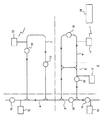
図1〜図6に天井走行車システム2を例に実施例を示す。天井走行車の走行エリアは、例えばエリア3〜7のように分割されている。天井走行車システム2では、図示しない走行レールと給電レールとが平行に例えば上下に重ねて敷設され、図示しない電源から給電レールに設けた給電線に給電する。さらに給電線をエリアコントローラ12に接続して、給電線を介して天井走行車10との間で有線通信する。天井走行車10はピックアップコイルなどを給電線に近接させて、非接触でかつ所定の周波数で給電線との間の信号の送受信を行う。例えば給電線での非接触給電用の電流を10KHz、エリアコントローラ12との通信用の周波数を200KHzなどとし、給電用の周波数と通信用の周波数とを例えば10倍以上変えると、給電と通信とを同じ線を用いて行うことができる。非接触給電の給電線には長さに限界があり、給電線はループ状に配置され、エリアコントローラ12は1本の非接触給電線がカバーするエリア毎に設ける。また分岐部や合流部ではデッドロックなどが生じやすいので、1つの分岐部や1つの合流部は1つのエリアコントローラで管理し、2つのエリアコントローラに分配しない。
1 to 6 show an embodiment of an overhead
天井走行車10は天井走行車システム2に沿って多数台配置され、大規模なシステムでは100台以上配置される。天井走行車10は走行レールに沿って走行し、給電線から給電と有線通信とを行い、各エリアではそのエリアのエリアコントローラ12と通信して、その指示に従う。また天井走行車10はこれ以外に、無線通信でシステムコントローラ14と、直接あるいはエリアコントローラを介して、通信できる。無線通信は通信容量が小さいので、例えばシステムコントローラ14からの搬送指令の送信などの所定の通信に用い、他の通信は給電線兼用の通信線を介して行う。なお走行レールに専用の通信線を設けて、通信するようにしても良い。
Many
エリアコントローラ12は各天井走行車10から受信したその位置並びに状態を、システムコントローラ14へ図示しないLANなどを介して送信し、システムコントローラ14から受けた指示を天井走行車10へ有線通信などで指示する。天井走行車10の状態には、例えば走行中、待機状態で停止中、ルートが塞がっているため停止中、荷掴み中、荷下ろし中、走行モータの不良などで低速走行中、(特殊な事情により)逆向きに走行中、故障で停止中(復旧まで移動不能)、などがあり、好ましくはこれ以外に、次の走行先に関する情報、例えば走行の目的ステーション、あるいは次に経由する予定のポイントなどを含める。
The
図2に天井走行車10の構成を示すと、マップ20には走行ルートの配置、即ち走行レールの配置とこれに沿ったステーションの配置などが記載され、ステーション間の距離なども読み取れるようにしてある。また他の天井走行車の位置と状態をマップ上に書き込み、衝突やデッドロックの回避などに役立てる。例えば他の天井走行車が、システムコントローラに現在位置と走行先並びに搬送中や荷下ろし中、荷掴み中、トラブル(故障)などの状態を報告すると、天井走行車はこれを傍受して、マップ20上に他の天井走行車の現在位置とその状態並びに今後の走行方向を記憶する。
FIG. 2 shows the configuration of the
天井走行車10は自己の絶対位置を認識しているので、マップから他の天井走行車との車間距離が判明し、かつ先行の天井走行車の状態(停止中または走行中)も判明するので、車間距離をつめてもかつ高速走行しても衝突を回避できる。天井走行車10は他の天井走行車の位置と状態を認識できるので、自己の判断であるいはシステムコントローラ14からの指示で、デッドロックなどを回避する。例えば分岐部や合流部あるいはバイパス部などで、マップ20から他の天井走行車の現在位置と次の走行先が判明すると、自己の走行との干渉の有無を判断でき、デッドロックが生じるかどうかを認識できる。
Since the
絶対位置センサ21は走行ルートに沿った天井走行車10の絶対位置(外界センサで求めた位置)を検出する。絶対位置センサ21に例えばレーザ位置センサなどを用いて、所定の位置に反射板などを設けて、天井走行車10の絶対位置を検出するようにしても良い。これ以外に走行ルートに沿って所定位置にマークなどを設けて、絶対位置センサでこれを検出すると、マークを通過する毎に絶対位置を求めることができる。エンコーダ22は天井走行車のサーボモータや走行車輪などの回転数を検出して、絶対位置センサ21が間欠的に絶対位置を検出する場合、絶対位置の検出と絶対位置の検出との間で、天井走行車10の位置並びに速度を検出する。
The
天井走行車10は、給電レールに沿って非接触給電部24と有線通信部25とを備え、非接触給電は10KHz程度の周波数で行われ、有線通信は200KHz程度の周波数で行われるので、これらを同じ線を用いて同時に行うことができる。無線通信部26は、フィーダー通信などによりシステムコントローラやエリアコントローラなどと通信する。なお無線通信部26は設けなくても良い。天井走行車10にはこれ以外に汎用のメモリ28とCPU30とを設けて、種々の判断と制御とを行う。走行駆動部32は天井走行車10の走行駆動を行い、ラテラルドライブ33は昇降駆動部34を走行レールの左右方向に移動させ、昇降駆動部34と回動駆動部35とで、チャック部36を回動させかつ昇降させて、適宜のステーションとの間で物品の移載を行う。
The
図3にシステムコントローラ14の構成を示すと、通信インターフェース40はイーサネットなどのLANを介して、エリアコントローラ12との間で通信を行い、エリアコントローラ12経由で各天井走行車10の現在位置並びに状態を受信し、各天井走行車10に対する走行や搬送の指示を与える。無線通信部41はエリアコントローラ12を経由せずに直接天井走行車10と通信するが、通信容量が小さい場合が多く、半導体処理設備などのレイアウトなどによっては通信が困難な場所などが生じ得る。通信インターフェース42は別途のLANなどを介して、搬送と生産の双方をコントロールする上位コントローラ43などと通信し、搬送要求を受け付け、搬送結果を報告する。
FIG. 3 shows the configuration of the
天井走行車管理部44は、天井走行車の状態と現在位置を管理し、例えば天井走行車ファイル45に各天井走行車の現在位置と状態を記憶すると共に、マップ46にも天井走行車の位置と状態などを記述し、マップからでも天井走行車の号機番号からでも、その現在位置と状態を管理できるようにする。なお天井走行車ファイル45とマップ46は何れか一方のファイルを設ければよく、これらのファイルの違いは例えば、天井走行車ファイル45は天井走行車の号機や状態などから検索するファイルで、マップ46は走行ルート上の位置から検索するファイルである点である。搬送管理部48は、上位コントローラ43から受け付けた搬送要求のファイルを記憶すると共に、実行済みの搬送要求や割付済みで実行中の搬送要求、未割付の搬送要求などのように搬送結果のファイルを記憶する。50は汎用のメモリである。
The overhead traveling
天井走行車は1つのエリア内では、他の天井走行車の位置と状態とを、システムコントローラとの通信を傍受することにより認識できる。しかしながら他のエリアでの天井走行車の位置や状態は認識できない。このため天井走行車にはシステムコントローラから搬送の指示以外に種々の指示を与える。しかし1つのエリア内でのデッドロックや衝突の回避などの場合、システムコントローラからの指示を待たずに、各天井走行車が自己の判断で処理を行う。
The overhead traveling vehicle can recognize the position and state of another overhead traveling vehicle by intercepting communication with the system controller in one area. However, the position and state of the overhead traveling vehicle in other areas cannot be recognized. For this reason, various instructions are given to the overhead traveling vehicle from the system controller in addition to the conveyance instruction. However, in the case of deadlock or collision avoidance in one area, each overhead traveling vehicle performs processing based on its own judgment without waiting for an instruction from the system controller.
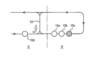
図4はジャミングの防止を示し、例えばエリア6の先頭の天井走行車10cがトラブルを起こして移動できず、このため後続の天井走行車10b及び10aも停止しているとする。システムコントローラ14は単に天井走行車10a〜10cがエリア6にいることを認識しているのみでなく、天井走行車10cがトラブルを起こしていることも認識している。このため後続の天井走行車10dに対して、例えばバイパス52を介してエリア6を迂回するように指示でき、ジャミングが拡がるのを防止できる。また天井走行車10a,10bの状態が正常であることと、その現在位置、特に天井走行車10a,10bの位置の順序を、システムコントローラが認識しているので、天井走行車10a,天井走行車10bの順でバックさせて、バイパス52から脱出させることも可能である。なお天井走行車が走行中のエリア内でジャミングが生じている場合、可能で有れば、システムコントローラからの指示を待たずに、ジャミング回避のために走行経路を変更する。ただしこの場合、走行経路を変更した天井走行車は、エリアコントローラなどを介してシステムコントローラにその旨報告する。
FIG. 4 shows prevention of jamming. For example, it is assumed that the top
図5はデッドロックの回避を模式的に示し、天井走行車10eと天井走行車10fとがバイパス52を互いに逆方向に走行しようとしている例である。この場合バイパス52やその両端の分岐合流部を同じエリア5内に配置しておくことにより、天井走行車10eは他の天井走行車10fがバイパス52に進入しようとしているので、デッドロックが生じることを認識できる。そこで例えば天井走行車10eが一旦停止し、バイパス52へ走行したいとの状態から、停止中へ状態を変更した旨をシステムコントローラに送信する。するとシステムコントローラから天井走行車10fに対してバイパス52へ進入することを指示でき、あるいはシステムコントローラからの指示を待たずに、天井走行車10eとシステムコントローラからの通信を傍受して、天井走行車10fがバイパス52へ進入することもできる。このようにして簡単にデッドロックを回避できる。
FIG. 5 schematically shows avoidance of deadlock, and is an example in which the
図6は、エリア54で荷掴み要求が多発しているので、天井走行車10をなるべくエリア54に配備する必要がある例を示している。荷掴み要求の発生場所は、システムコントローラが上位コントローラから搬送要求として受け付け、空きの天井走行車10g,10hが付近のエリア55,56にいることをシステムコントローラが認識すると、エリア54への移動を指令する。このようにして、荷掴み要求に応じて天井走行車を配備できる。
FIG. 6 illustrates an example in which the
実施例は天井走行車について示したが、地上走行の有軌道台車などでも良く、移載装置を搭載するか否かは任意である。 Although the embodiment has been described with respect to the overhead traveling vehicle, it may be a tracked railcar or the like, and whether or not the transfer device is mounted is arbitrary.
実施例では以下の効果が得られる。
(1) 非接触給電用の給電線を利用して、天井走行車とシステムコントローラとの間で通信を行うことができ、通信容量を著しく増すことができる。このため天井走行車の位置のみでなく、状態をコントローラに報告できる。さらに同じエリア内であれば、他の天井走行車の通信を傍受できる。
(2) システムコントローラは各天井走行車の位置と状態とを認識でき、また天井走行車も同じエリア内の他の天井走行車の位置と状態とを認識できる。
(3) これらのため天井走行車は、車間距離を詰めながら衝突を回避しながら高速走行できる。またジャミングやデッドロックを防止でき、荷掴み要求が多発しているエリアに空きの天井走行車を多数配備できる。さらに優先度の高い搬送指令に対して、直近の空きの天井走行車を割り付けることができる。また他の天井走行車の位置や状態から所要走行時間を正確に予測でき、さらに最短時間で走行できるルートを選択できる。
In the embodiment, the following effects can be obtained.
(1) Communication can be performed between the overhead traveling vehicle and the system controller by using a non-contact power feeding line, and the communication capacity can be significantly increased. For this reason, not only the position of the overhead traveling vehicle but also the state can be reported to the controller. Furthermore, if it is in the same area, communication of other overhead traveling vehicles can be intercepted.
(2) The system controller can recognize the position and state of each overhead traveling vehicle, and the overhead traveling vehicle can also recognize the position and state of other overhead traveling vehicles in the same area.
(3) For these reasons, overhead traveling vehicles can travel at high speeds while avoiding collisions while reducing the distance between vehicles. In addition, jamming and deadlock can be prevented, and a large number of free overhead traveling vehicles can be deployed in areas where cargo handling requests are frequently generated. Furthermore, the nearest empty overhead traveling vehicle can be assigned to a transport command having a higher priority. In addition, the required travel time can be accurately predicted from the position and state of other overhead traveling vehicles, and a route that can travel in the shortest time can be selected.
2 天井走行車システム
3〜7 エリア
10 天井走行車
12 エリアコントローラ
14 システムコントローラ
20 マップ
21 絶対位置センサ
22 エンコーダ
24 非接触給電部
25 有線通信部
26 無線通信部
28 メモリ
30 CPU
32 走行駆動部
33 ラテラルドライブ
34 昇降駆動部
35 回動駆動部
36 チャック部
40,42 通信インターフェース
41 無線通信部
43 上位コントローラ
44 天井走行車管理部
45 天井走行車ファイル
46 マップ
48 搬送管理部
50 メモリ
52 バイパス
54〜56 エリア
2 Overhead traveling vehicle system 3-7
32
Claims (3)
前記複数の有軌道台車の走行エリアを、1つの分岐部や1つの合流部、並びに1つのバイパスとその両端の分岐部や合流部とを、2つのエリアに分配せずに1つのエリア内に含めるように、複数のエリアに分割すると共に、前記複数の有軌道台車に非接触給電するための給電線を、走行エリア内の走行経路に沿って設け、
各エリア毎に、前記給電線とシステムコントローラとに接続したエリアコントローラを設けて、エリアコントローラとエリア内の有軌道台車が、前記給電線を介して非接触給電用の周波数とは異なる周波数で互いに通信して、有軌道台車が自己の位置と状態とをエリアコントローラに報告するようにし、
さらに各有軌道台車に、前記給電線を介しての、エリア内の他の有軌道台車とエリアコントローラとの通信を傍受するための手段と、
傍受した他の有軌道台車の位置から、自己の走行を制御するための手段とを設けたことを特徴とする、有軌道台車システム。 A plurality of tracked carts are provided with means for recognizing the current position and the system controller, and the system controller instructs the tracked carts according to the current position and state of the other tracked carts. In a tracked carriage system that transmits
The traveling area of the plurality of tracked carriages is divided into one area without dividing one branch part or one junction part and one bypass and branch parts or junction parts at both ends thereof into two areas. Including, to divide into a plurality of areas, providing a power supply line for non-contact power supply to the plurality of tracked carriages along a travel route in the travel area,
For each area, an area controller connected to the power supply line and the system controller is provided, and the area controller and the tracked carriage in the area communicate with each other at a frequency different from the frequency for non-contact power supply via the power supply line. Communicate so that the tracked cart reports its position and status to the area controller,
Furthermore, means for intercepting communication between the other tracked carriages in the area and the area controller via the feeder line to each tracked carriage,
A tracked carriage system comprising means for controlling own traveling from the position of another tracked carriage that has been intercepted .
The tracked cart system according to claim 1 or 2, characterized in that travel control is performed by obtaining an inter-vehicle distance from the position of another tracked cart that has been intercepted.
Priority Applications (5)
| Application Number | Priority Date | Filing Date | Title |
|---|---|---|---|
| JP2004004302A JP3874192B2 (en) | 2004-01-09 | 2004-01-09 | Tracked cart system |
| TW093124691A TW200523190A (en) | 2004-01-09 | 2004-08-17 | Rail guided vehicle system |
| KR1020040086192A KR100810528B1 (en) | 2004-01-09 | 2004-10-27 | Track carriage system |
| EP04028847.4A EP1553000B1 (en) | 2004-01-09 | 2004-12-06 | Rail guided vehicle system |
| US11/008,183 US7303169B2 (en) | 2004-01-09 | 2004-12-10 | Rail guided vehicle system |
Applications Claiming Priority (1)
| Application Number | Priority Date | Filing Date | Title |
|---|---|---|---|
| JP2004004302A JP3874192B2 (en) | 2004-01-09 | 2004-01-09 | Tracked cart system |
Publications (2)
| Publication Number | Publication Date |
|---|---|
| JP2005196655A JP2005196655A (en) | 2005-07-21 |
| JP3874192B2 true JP3874192B2 (en) | 2007-01-31 |
Family
ID=34587726
Family Applications (1)
| Application Number | Title | Priority Date | Filing Date |
|---|---|---|---|
| JP2004004302A Expired - Fee Related JP3874192B2 (en) | 2004-01-09 | 2004-01-09 | Tracked cart system |
Country Status (5)
| Country | Link |
|---|---|
| US (1) | US7303169B2 (en) |
| EP (1) | EP1553000B1 (en) |
| JP (1) | JP3874192B2 (en) |
| KR (1) | KR100810528B1 (en) |
| TW (1) | TW200523190A (en) |
Families Citing this family (20)
| Publication number | Priority date | Publication date | Assignee | Title |
|---|---|---|---|---|
| JP4221603B2 (en) * | 2005-03-31 | 2009-02-12 | 村田機械株式会社 | Overhead traveling vehicle system |
| JP4281067B2 (en) * | 2005-04-11 | 2009-06-17 | 村田機械株式会社 | Transport vehicle system |
| JP4438095B2 (en) * | 2005-05-26 | 2010-03-24 | 村田機械株式会社 | Transport system |
| ITMI20051393A1 (en) * | 2005-07-20 | 2007-01-21 | Marsilli & Co | AUTOMATIC PRODUCTION LINE FOR PROCESSING AND ASSEMBLY OF COMPONENTS FOR INDUSTRIES IN GENERAL |
| JP4172477B2 (en) * | 2005-08-17 | 2008-10-29 | 村田機械株式会社 | How to implement pattern on actual machine |
| KR100944154B1 (en) | 2005-09-13 | 2010-02-24 | 무라타 기카이 가부시키가이샤 | Track carriage system |
| JP5002347B2 (en) * | 2007-06-22 | 2012-08-15 | 中西金属工業株式会社 | Tracked transportation system |
| TW201013820A (en) * | 2008-09-24 | 2010-04-01 | Inotera Memories Inc | Automatic transport system and control method thereof |
| JP5088415B2 (en) * | 2008-09-26 | 2012-12-05 | 村田機械株式会社 | Transport vehicle system |
| JP5146855B2 (en) * | 2010-08-09 | 2013-02-20 | 村田機械株式会社 | Overhead traveling vehicle system |
| US8996161B2 (en) | 2011-05-19 | 2015-03-31 | Rockwell Automation, Inc. | Controlled architecture for transport systems |
| CN102372014B (en) * | 2011-10-28 | 2014-05-07 | 中冶南方工程技术有限公司 | Automatic locomotive collision prevention method in molten iron transportation logistics simulation system of metallurgical works |
| JP5527619B2 (en) * | 2011-11-24 | 2014-06-18 | 株式会社ダイフク | Ceiling-mounted goods transport equipment |
| US20140180501A1 (en) * | 2012-07-03 | 2014-06-26 | Modutram Mexico, S.A. De D.V. | Control system and method for automated vehicle fleet |
| KR101440569B1 (en) * | 2013-06-04 | 2014-09-17 | (주)엔스퀘어 | System for managing automatic guided vehicles |
| IL230866A0 (en) * | 2014-02-06 | 2014-09-30 | Dan Yehuda Schlesinger | Overhead handling device |
| US10181873B2 (en) * | 2015-12-28 | 2019-01-15 | Stmicroelectronics, Inc. | Enhanced powerline communication methods and devices |
| JP6698399B2 (en) * | 2016-03-29 | 2020-05-27 | 北陽電機株式会社 | Transfer control device and method for passing a confluence point of a carrier |
| TWI694022B (en) * | 2018-03-01 | 2020-05-21 | 正修學校財團法人正修科技大學 | Rail three-dimensional detection system |
| MX2022006818A (en) | 2018-04-06 | 2022-07-11 | Sst Systems Inc | Conveyor system with automated carriers. |
Family Cites Families (7)
| Publication number | Priority date | Publication date | Assignee | Title |
|---|---|---|---|---|
| US4766547A (en) * | 1986-04-14 | 1988-08-23 | Transfer Technologies, Inc. | Computer controlled conveyor system |
| JPS6373304A (en) * | 1986-09-16 | 1988-04-02 | Shinko Electric Co Ltd | Device for preventing collision of unmanned vehicle |
| JPH05324064A (en) * | 1992-05-26 | 1993-12-07 | Toshiba Corp | Orbital truck controller |
| TW386875B (en) * | 1995-01-11 | 2000-04-11 | Shinko Electric Co Ltd | Transportation system |
| JPH10268937A (en) | 1997-03-24 | 1998-10-09 | Murata Mach Ltd | Operation control system for on-track wagon |
| DE19822803A1 (en) * | 1998-05-20 | 1999-11-25 | Alcatel Sa | Process for operating rail vehicles and train control center and vehicle device therefor |
| CA2633590C (en) | 2001-10-22 | 2011-11-15 | Cascade Engineering, Inc. | Individual transport control and communication system |
-
2004
- 2004-01-09 JP JP2004004302A patent/JP3874192B2/en not_active Expired - Fee Related
- 2004-08-17 TW TW093124691A patent/TW200523190A/en not_active IP Right Cessation
- 2004-10-27 KR KR1020040086192A patent/KR100810528B1/en active IP Right Grant
- 2004-12-06 EP EP04028847.4A patent/EP1553000B1/en not_active Expired - Fee Related
- 2004-12-10 US US11/008,183 patent/US7303169B2/en not_active Expired - Fee Related
Also Published As
| Publication number | Publication date |
|---|---|
| EP1553000B1 (en) | 2017-04-26 |
| KR100810528B1 (en) | 2008-03-10 |
| TWI324130B (en) | 2010-05-01 |
| JP2005196655A (en) | 2005-07-21 |
| US20050150416A1 (en) | 2005-07-14 |
| US7303169B2 (en) | 2007-12-04 |
| KR20050073515A (en) | 2005-07-14 |
| TW200523190A (en) | 2005-07-16 |
| EP1553000A1 (en) | 2005-07-13 |
Similar Documents
| Publication | Publication Date | Title |
|---|---|---|
| JP3874192B2 (en) | Tracked cart system | |
| CN107291076B (en) | Article conveying apparatus | |
| TWI493309B (en) | Walking control system and control method of running | |
| JP5928402B2 (en) | Traveling vehicle control system | |
| JP4281067B2 (en) | Transport vehicle system | |
| TWI539254B (en) | Vehicle system and vehicle control method | |
| KR20170077823A (en) | Article transport facility | |
| KR20180092875A (en) | Article transport facility | |
| CN102037422A (en) | Traveling vehicle system and method for controlling traveling by traveling vehicle system | |
| JP4099723B2 (en) | Conveyor cart system | |
| KR20180123979A (en) | Article transport facility | |
| JP4471118B2 (en) | Goods transport equipment | |
| JP2009237866A (en) | Conveyance system and carrier | |
| JP2005306570A (en) | Conveyance system | |
| CN113906359A (en) | Traveling system | |
| JP5170190B2 (en) | Transport vehicle system | |
| JP4360344B2 (en) | Conveyor cart system | |
| US11217092B2 (en) | Transport vehicle system | |
| WO2023079797A1 (en) | Conveyance system | |
| JP7294029B2 (en) | Goods transport equipment | |
| KR20110108953A (en) | Method for controlling traffic of autonomous guided vehicle using path tracking | |
| WO2020152793A1 (en) | Travel control apparatus, travel control method, and non-transitory computer readable medium storing program thereon | |
| JPH01220008A (en) | Carriage controller | |
| JP2003208223A (en) | Unmanned carrier system | |
| JPH07191745A (en) | Traveling vehicle control equipment |
Legal Events
| Date | Code | Title | Description |
|---|---|---|---|
| A977 | Report on retrieval |
Free format text: JAPANESE INTERMEDIATE CODE: A971007 Effective date: 20060713 |
|
| A131 | Notification of reasons for refusal |
Free format text: JAPANESE INTERMEDIATE CODE: A131 Effective date: 20060724 |
|
| A521 | Request for written amendment filed |
Free format text: JAPANESE INTERMEDIATE CODE: A523 Effective date: 20060913 |
|
| TRDD | Decision of grant or rejection written | ||
| A01 | Written decision to grant a patent or to grant a registration (utility model) |
Free format text: JAPANESE INTERMEDIATE CODE: A01 Effective date: 20061005 |
|
| A61 | First payment of annual fees (during grant procedure) |
Free format text: JAPANESE INTERMEDIATE CODE: A61 Effective date: 20061018 |
|
| R150 | Certificate of patent or registration of utility model |
Ref document number: 3874192 Country of ref document: JP Free format text: JAPANESE INTERMEDIATE CODE: R150 Free format text: JAPANESE INTERMEDIATE CODE: R150 |
|
| FPAY | Renewal fee payment (event date is renewal date of database) |
Free format text: PAYMENT UNTIL: 20121102 Year of fee payment: 6 |
|
| R250 | Receipt of annual fees |
Free format text: JAPANESE INTERMEDIATE CODE: R250 |
|
| FPAY | Renewal fee payment (event date is renewal date of database) |
Free format text: PAYMENT UNTIL: 20131102 Year of fee payment: 7 |
|
| R250 | Receipt of annual fees |
Free format text: JAPANESE INTERMEDIATE CODE: R250 |
|
| FPAY | Renewal fee payment (event date is renewal date of database) |
Free format text: PAYMENT UNTIL: 20131102 Year of fee payment: 7 |
|
| R250 | Receipt of annual fees |
Free format text: JAPANESE INTERMEDIATE CODE: R250 |
|
| R250 | Receipt of annual fees |
Free format text: JAPANESE INTERMEDIATE CODE: R250 |
|
| R250 | Receipt of annual fees |
Free format text: JAPANESE INTERMEDIATE CODE: R250 |
|
| R250 | Receipt of annual fees |
Free format text: JAPANESE INTERMEDIATE CODE: R250 |
|
| R250 | Receipt of annual fees |
Free format text: JAPANESE INTERMEDIATE CODE: R250 |
|
| R250 | Receipt of annual fees |
Free format text: JAPANESE INTERMEDIATE CODE: R250 |
|
| LAPS | Cancellation because of no payment of annual fees |