JP3871114B2 - Blow molding container - Google Patents
Blow molding container Download PDFInfo
- Publication number
- JP3871114B2 JP3871114B2 JP2001335631A JP2001335631A JP3871114B2 JP 3871114 B2 JP3871114 B2 JP 3871114B2 JP 2001335631 A JP2001335631 A JP 2001335631A JP 2001335631 A JP2001335631 A JP 2001335631A JP 3871114 B2 JP3871114 B2 JP 3871114B2
- Authority
- JP
- Japan
- Prior art keywords
- outer layer
- blow
- inner layer
- adhesive
- container
- Prior art date
- Legal status (The legal status is an assumption and is not a legal conclusion. Google has not performed a legal analysis and makes no representation as to the accuracy of the status listed.)
- Expired - Fee Related
Links
Images


Landscapes
- Containers Having Bodies Formed In One Piece (AREA)
- Blow-Moulding Or Thermoforming Of Plastics Or The Like (AREA)
Description
【0001】
【産業上の利用分野】
本発明は、定形の外殻を形成する外層内に、変形自在な内袋を形成する内層を剥離自在に積層形成し、外観形状を変化させることなく、内容液の注出使用を可能とした積層剥離合成樹脂製ブロー成形容器に関するものである。
【0002】
【従来の技術】
定形の外殻を形成する外層内に、変形自在な内袋を形成する内層を剥離自在に積層して構成した、一般にデラミボトルと称されるブロー成形壜体である積層剥離合成樹脂製容器が知られている。
【0003】
このブロー成形された積層剥離合成樹脂製容器は、相溶性の殆どない外層パリソンと内層パリソンとを共押出しで積層パリソンに押出し成形し、この積層パリソンをブロー成形して得られるが、ブロー金型のピンチオフ部で押し潰し成形される底シール部分は、基本的には相溶性の殆どない外層部分と内層部分との積層構造となるため、外層部分に容易に底割れが発生すると云う不満があった。
【0004】
この不満を解消する従来技術として、ブロー金型のピンチオフ部により偏平に押し潰されて成形される底シール部を、一対のリブ片を重合圧着してパーティングラインに沿った突条状に成形し、この突条状物に、一対のリブ片の一方から他方に食い込む食い込み部を複数設けて構成した技術(特開平8−216238号公報参照)がある。
【0005】
この従来技術は、底シール部を高さ幅を有する突条状とすることにより、底シール部における外層と内層との圧着面積を大きくし、また複数の食い込み部を設けることにより、外層と内層との圧着面積をさらに増大させるばかりでなく、圧着面に平行する剪断力に対する抗力を飛躍的に高め、これにより底割れの発生し難い、機械的強度の高い底シール部を得ることを可能としている。
【0006】
【発明が解決しようとする課題】
しかしながら、上記した従来技術にあっては、容器のブロー成形完了後における底部の経時収縮の影響により、底シール部に底割れが発生する場合があり、特に大型の容器にあっては、内容液を充填した状態で落としたり、衝撃を与えたりすると、底割れがしばしば発生する、と云う問題があった。
【0007】
それゆえ、この種のブロー成形容器は、金型内で収縮、すなわち冷却収縮を完了させる必要があるが、底シール部は大きな高さ幅と厚みとを有するので、その体積が大きなものとなり、このため冷却に長時間を要し、容器の生産効率をきわめて低いものとしてしまう、と云う問題があった。
【0008】
そこで、本発明は、上記した従来技術における問題点を解消すべく創案されたもので、底シール部の体積を増大させることなく、底シール部における内層と外層の強固な結合を達成することを技術的課題とし、もって生産効率を高くし、強度および経済性に優れた、積層剥離合成樹脂製ブロー成形容器を提供することを目的とする。
【0009】
【課題を解決するための手段】
上記技術的課題を解決する本発明の手段の内、請求項1記載の発明の手段は、ブロー成形により、定形の外殻を形成する合成樹脂製の外層と、
外層と剥離自在に積層され、内袋を形成する可撓性合成樹脂製の内層と、
外層と内層とを、全高さ範囲に亘って接着固定し、容器の中心軸に関して略対称に、かつ前記外層に形成された、外層と内層との間に外気を侵入させる吸気孔を避けて位置した縦細帯状の2対、計4本の接着帯と
から構成すること、
接着帯の2本づつを、パーティングラインを境として、互いに反対側に位置させると共に、ブロー割金型のピンチオフ部により偏平に押し潰されて成形される底部の底シール部における各接着帯の下端縁全幅を、反対側の接着帯の下端縁と一対一で突き合わせ状に対向位置させること、
にある。
【0010】
容器は、通常のピンチオフ部構造を有するブロー金型、すなわちブロー成形割り金型でブロー成形されるので、底部に形成される喰い切り部である底シール部は、通常のブロー成形品と同様に、低い突出高さの突条状となる。
【0011】
このように、この底シール部の体積は、通常のブロー成形品の底シール部と同様に、充分に小さいので、容器の離型に際しての、底シール部に対する冷却は、速やかにかつ充分に達成できることになる。
【0012】
接着帯の2本づつを、パーティングラインを境として、互いに反対側に位置させると共に、底シール部における各接着帯の下端縁全幅を、反対側の接着帯の下端縁と一対一で突き合わせ状に位置させており、この2箇所の突き合わせ部分では、パーティングラインの両側の外層とこの両外層に挟まれる内層は、接着帯の下端縁の幅の範囲で、接着帯を介して強固に接着固定された状態となる。
【0013】
また、2箇所の接着帯の突き合わせ状部分の間の領域は接着帯は存在しないが、その両側において外層と内層が接着帯を介して強固に接着されているので、外層と内層は一体となった変形を示し、その結果、両接着帯の幅と接着帯間部分の幅を合わせた幅広い領域で外層と内層が強固に接着した接着固定部分とすることができる。
【0014】
上記のような接着固定部と底シ−ル部の左右端部の3ヶ所が、外層と内層からなる積層体の底シール部における変形に対して結節点の機能を果たし、底シール部の、接着固定部分以外の部分においても、外層および内層単独での変形は抑制され、その結果、底シール部になんらかの力が負荷された状態でも、この力に対抗することができ、底シール部の割れを防止することが可能となるが、接着帯間部分の幅も含めて広い範囲を接着固定部とすることが可能であり、結節点としての機能が確実に発揮され、外層および内層単独での変形を効果的に抑制するので、充分な割れ防止効果を得ることができる。
【0015】
上記のように、両接着帯幅と接着帯間部分の幅を合わせた幅広い領域で外層と内層が一体化した挙動を示すので、接着帯の幅自体は狭く設定することが可能であり、材料コストの高い接着性材料の使用量を少なくすることが可能である。
【0016】
全高さ範囲に亘って位置した接着帯は、内層の萎み変形を規制する機能を果たし、内容物の注出をスムーズに達成することが可能となる。
【0017】
請求項2記載の発明は、請求項1記載の発明の構成に、容器の中心軸に関して略軸対称に、パーティングライン近傍の2箇所の外層部分に設けたことを加えたものである。
【0018】
上記請求項2の構成により、パーティングラインを境として同方向に位置する2本の接着帯の間の領域では、外気の浸入がないので、外層と内層の剥離が進行することがなく、底シール部の2箇所の接着帯の突き合わせ状部分の間の領域の外層と内層の一体化をより確実に保持することが可能となる。
【0019】
また、2本の接着帯幅と、接着帯の間の幅を加えた領域が内層の萎み変形を規制する機能を果たすので、接着帯の幅自体を狭くすることが可能である。
【0020】
請求項3記載の発明は、請求項2記載の発明の構成に、パーティングラインを境として、同方向に位置する2本の接着帯間の幅を、萎み変形可能な内層の部分が、内容物を使い切った段階で、容器の胴部の平断面をちょうど塞ぐことができるように設定したものである。
【0021】
上記請求項3の構成により、内容物がまだ残存した状態での胴部平断面の完全な潰れ変形を防ぐことができ、また内容物を略使い切った状態で、胴部平断面が完全に潰れるので、内容物の流動通路を確保し、良好な注出性を保持しながら、内容物のほぼ全量使い切ることが可能となる。
【0022】
請求項4記載の発明は、請求項1、2または3記載の発明の構成に、吸気孔を、口筒部の外層部分に設けた、ことを加えたものである。
【0023】
この請求項4記載の発明においては、吸気孔を、キャップで覆われる口筒部に開設するので、この吸気孔が容器の外観を劣化させることがなく、またこの吸気孔を後加工で切り取り成形するに際して、口筒部における内層部分の肉厚が大きいので、この吸気孔の切り取り成形を、内層部分に穴を開けることなく、容易に行うことができる。
【0024】
【発明の実施の形態】
以下、本発明の実施例を、図面を参照しながら説明する。
図1ないし図7は、本発明による容器1の一実施例を示すもので、この容器1は、ポリエチレン、ポリプロピレン等の合成樹脂材料で、必要とする自己形状保持能力を持たせた外殻体として成形された外層2と、ナイロン、エチレンビニルアルコール共重合体、ポリエチレンテレフタレート等の外層2に対して相溶性の低い合成樹脂材料で、撓み変形が自在な袋状に成形された内層3と、外層2および内層3に対して充分な接着性を発揮する接着性樹脂で成形され、容器1の全高さ範囲に亘って設けられた縦細帯状の2対、計4本の接着帯4とを積層させたブロー成形容器である。
【0025】
この容器1の胴部6は円筒形状をしており、胴部6の上端に起立連設され、外周面に螺条を刻設した口筒部7の左右のパーティングライン5の位置の外層2部分には、外気を外層2と内層3との間に導入するための吸気孔9が開設されている。
【0026】
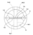
上記吸気孔9に対して略中心角90°変位した位置を挟んで、接着帯4が4本(4a1、4a2、4b1、4b2)位置しており、このうち4a1と4b2および4a2と4b1は軸対称の位置にあり、胴部6においてパーティングライン5を境に同じ側にある2本の接着帯4(4a1と4b1および4a2と4b2)とこの2本の接着帯4に挟まれた部分を合わせた領域(以下、固定帯13と記す。)の幅が(1/4)(L−2D)となるように設定している。(L;胴部平断面の周長、D;胴部平断面の直径)
【0027】
胴部6の下端には、球弧状に陥没した底壁を有する底部8が連設されており、この底部8(図3、図4参照)は、底壁の周囲に、容器1の脚部を形成し、この底壁の下面中央に、パーティングライン5上に位置して底壁を略横断する、ブロー金型のピンチオフ部で押し潰し喰い切り成形された、底シール部10を形成した構成となっている。
【0028】
容器1のブロー成形は、外層2となる外筒と、この外筒の内側に位置する内層3となる内筒と、外筒と内筒との間の、対称位置に2対設けられた縦細帯状の接着帯4とを共押出ししてパリソンを押出し成形し、このパリソンをブロー成形割り金型で容器1にブロー成形する。
【0029】
この容器1のブロー成形に際して、パリソンは、その中心軸からブロー成形割り金型の型締め方向近傍に、2対、計4本の接着帯4を、位置させるように、ブロー成形割り金型に対する姿勢が設定されおり、図3に示すように、接着帯4は、底部8のパーティングライン5上に位置する底シール部10まで達する。
【0030】
また、パーティングライン5を境として反対側に位置する、接着帯4の4a1と4a2、および4b1と4b2は、図3および図6に示すように底シール部10において、その一方の下端縁の全幅が反対側の下端縁に一対一で突き合わせ状に位置する。(以下この2本の接着体が突き合わせ状に位置する部分を突き合わせ部12と記す。)
【0031】
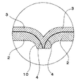
このため図5および図6に示すように、喰い切り部である底シール部10の、突き合わせ部12が位置する部分におけるパーティングライン5の両側の外層2とこの両外層2に挟まれる内層3とは、接着帯4により強固に接着固定され、さらに、この両突き合わせ部12の間の接着帯間部分14についても、その両側が突き合わせ部分12で固定されており、内層あるいは外層の単独の変形は抑制され、その結果、両接着帯4の幅と接着帯間部分14の幅を合わせた幅広い領域で、外層2と内層3との強固な結合が達成さる。
【0032】
また本実施例では、吸気孔9を口筒部7のパーティングライン5上に位置しているので、内圧の減少、内容物15の減少等による内層3の萎み変形は、パーティングライン5に対して略中心角90°変位した位置に形成される一対の固定帯13が変形を規制する機能を果たしながら、接着帯4a1と接着帯4a2の間、および接着帯4b1と接着帯4b2の間に位置する、2つの内層変形部11で進行する。
【0033】
内容物15の注出の進行にしたがって、胴部6の平断面で内層変形部11の変形の進行をみると、まずこの左右の内層変形部11の中央部が扁平状に変形し、さらに変形が進行し、略中央部で接触、さらに内容物15を周方向、固定帯13が形成された部分に押し付けるようにこの接触部が伸展しながら理想的には左右対称な形で、萎み変形が進行する。(図7参照)
【0034】
さらに内容物15の注出が進み、萎み変形が進むと、内容物15がほとんど無くなった状態で、平断面が略完全に潰れた状態に近づくが、ここで、内層変形部11の長さを胴部6平断面の径Dと固定帯13の幅との和に等しく、すなわち固定帯13の幅を(1/4)(L−2D)に等しくなるよう設定することにより内容物15の流動通路を確保しながら内容物15を略使い切ることが可能となる。
【0035】
なお、上記した実施例においては、容器1を外層2と内層3との二層構造として説明したが、内層3は単層構造に特定されるものではなく、例えば外側に外層2との剥離性を有する合成樹脂製の層を、そして内側に耐内容液性に優れた合成樹脂製の層を積層したものとしても良いことは云うまでもない。
【0036】
【発明の効果】
本発明は、上記した構成としたので、以下に示す効果を奏する。
請求項1記載の発明にあっては、容器の底部の底シール部に対する冷却を、速やかにかつ充分に達成できるので、容器の生産サイクルを、通常のブロー成形製品と同程度まで高めることができる。
【0037】
また、金型冷却効率を考慮した、特殊な金型を用いる必要がなく、通常の金型を使用することができるので、設備費の大幅な低減を達成できる。
【0038】
また、底シール部の外層と内層とを、2本の接着帯の幅と、この接着帯間の幅を合わせた幅広い領域で強固に結合することができるので、外層と内層とを剥離自在な合成樹脂材料で成形したことによる、底シール部の機械的強度の低下を確実にそして充分に防止することができる。
【0039】
さらに、計4本の接着帯を配置するが、上記のように接着帯間の幅も含めて強固な結合を達成する構成であり、接着帯の幅自体は狭く設定することが可能であり、材料コストの高い接着性材料の使用量を少なくすることができる。
【0040】
請求項2記載の発明にあっては、固定帯部分では内層の外層からの剥離が無いので、底シール部の2箇所の接着帯の突き合わせ状部分の間の領域の外層と内層の一体化をより確実に保持することが可能となる。
【0041】
請求項3記載の発明にあっては、内容物の流動通路を確保し、良好な注出性を保持しながら、内容物のほぼ全量使い切ることが可能となる。
【0042】
請求項4記載の発明にあっては、容器の外観体裁に悪影響を与えることなく、吸気孔を開設することができると共に、この吸気孔を安全にかつ簡単に、後加工により開設成形することができる。
【図面の簡単な説明】
【図1】本発明の一実施例を示す、一部破断した全体斜視図。
【図2】図1に示した実施例の、平断面図。
【図3】図1に示した実施例の、底面図。
【図4】図1に示した実施例の、底部拡大縦断面図。
【図5】図4中の、底シール部の拡大図。
【図6】図3中の、底シール部の拡大図。
【図7】図2に示した平断面図で、内層の変形の推移を示した説明図。
【符号の説明】
1 ; 容器
2 : 外層
3 ; 内層
4 ; 接着帯
4a1;接着帯
4a2;接着帯
4b1;接着帯
4b2;接着帯
5 ; パーティングライン
6 ; 胴部
7 ; 口筒部
8 ; 底部
9 ; 吸気孔
10; 底シール部
11; 内層変形部
12; 突き合わせ部分
13; 固定帯
14; 接着帯間部
15; 内容物[0001]
[Industrial application fields]
The present invention enables the inner layer forming a deformable inner bag to be peeled and laminated within the outer layer forming a fixed outer shell, and allows the content liquid to be poured out without changing the external shape. The present invention relates to a blow molded container made of a laminated release synthetic resin.
[0002]
[Prior art]
Known as a delaminated synthetic resin container, which is a blow-molded housing generally called a delamination bottle, which consists of an outer layer that forms a regular outer shell and an inner layer that forms a deformable inner bag. It has been.
[0003]
This blow-molded laminated exfoliated synthetic resin container is obtained by co-extrusion of an outer layer parison and an inner layer parison, which are almost incompatible, by extrusion molding into a laminated parison, and blow molding this laminated parison. The bottom seal part that is crushed and molded at the pinch-off part of this product is basically a laminated structure of an outer layer part and an inner layer part that have little compatibility, and there is a complaint that bottom cracks easily occur in the outer layer part. It was.
[0004]
As a conventional technology to eliminate this dissatisfaction, the bottom seal part, which is flattened by the pinch-off part of the blow mold, is molded into a ridge shape along the parting line by superposing and crimping a pair of rib pieces. However, there is a technique (see Japanese Patent Application Laid-Open No. 8-216238) in which a plurality of biting portions that bite from one of the pair of rib pieces to the other are provided on the protrusion.
[0005]
In this prior art, the bottom seal portion has a protrusion shape having a height and width, thereby increasing the pressure-bonding area between the outer layer and the inner layer in the bottom seal portion, and by providing a plurality of biting portions, the outer layer and the inner layer. In addition to further increasing the crimping area, the resistance against the shearing force parallel to the crimping surface is dramatically increased, thereby making it possible to obtain a bottom seal part with high mechanical strength that is less likely to cause bottom cracks. Yes.
[0006]
[Problems to be solved by the invention]
However, in the above-described prior art, bottom cracks may occur in the bottom seal part due to the effect of shrinkage of the bottom part after completion of the blow molding of the container. There is a problem that bottom cracks often occur when dropped in a state filled with or when an impact is applied.
[0007]
Therefore, this type of blow molded container needs to complete shrinkage in the mold, that is, cooling shrinkage, but the bottom seal portion has a large height width and thickness, so its volume becomes large, For this reason, there is a problem that it takes a long time for cooling, and the production efficiency of the container is extremely low.
[0008]
Therefore, the present invention was devised to solve the above-described problems in the prior art, and achieves a strong bond between the inner layer and the outer layer in the bottom seal portion without increasing the volume of the bottom seal portion. An object of the present invention is to provide a blow-molded container made of a laminated release synthetic resin, which is a technical problem, has high production efficiency, and is excellent in strength and economy.
[0009]
[Means for Solving the Problems]
Among the means of the present invention for solving the above technical problem, the means of the invention according to
An inner layer made of a flexible synthetic resin that is peelably laminated with an outer layer to form an inner bag;
The outer layer and the inner layer are bonded and fixed over the entire height range, and are positioned almost symmetrically with respect to the central axis of the container and avoiding the air intake holes formed in the outer layer between the outer layer and the inner layer. Composed of two pairs of vertical strips, a total of four adhesive strips,
Each of the two adhesive bands is positioned opposite to each other with the parting line as a boundary, and each adhesive band in the bottom seal portion of the bottom portion formed by being flattened and molded by the pinch-off portion of the blow split mold The bottom width of the entire width of the bottom edge is opposed to the bottom edge of the opposite adhesive band in a one-to-one manner,
It is in.
[0010]
Since the container is blow-molded with a blow mold having a normal pinch-off part structure, that is, a blow molding split mold, the bottom seal part, which is a biting part formed at the bottom, is the same as a normal blow-molded product. It becomes a ridge shape with a low protrusion height.
[0011]
As described above, the volume of the bottom seal portion is sufficiently small, like the bottom seal portion of ordinary blow molded products, so that the cooling of the bottom seal portion can be achieved quickly and sufficiently when releasing the container. It will be possible.
[0012]
Two adhesive strips are positioned on opposite sides of the parting line, and the bottom width of each adhesive strip at the bottom seal part is one-to-one with the bottom edge of the opposite adhesive strip. At the two butted parts, the outer layer on both sides of the parting line and the inner layer sandwiched between the two outer layers are firmly bonded via the adhesive band within the range of the width of the lower edge of the adhesive band. It becomes a fixed state.
[0013]
In addition, there is no adhesive band in the region between the butted portions of the two adhesive bands, but since the outer layer and the inner layer are firmly bonded via the adhesive band on both sides, the outer layer and the inner layer are integrated. As a result, it is possible to obtain an adhesive fixing portion in which the outer layer and the inner layer are firmly bonded in a wide region in which the width of both adhesive bands and the width of the portion between the adhesive bands are combined.
[0014]
The three points of the adhesive fixing part and the right and left end parts of the bottom seal part as described above serve as knot points against deformation in the bottom seal part of the laminate composed of the outer layer and the inner layer, Even in a portion other than the adhesive fixing portion, deformation of the outer layer and the inner layer alone is suppressed, and as a result, even when a force is applied to the bottom seal portion, this force can be counteracted and the bottom seal portion is cracked. However, it is possible to make a wide range including the width of the part between the adhesive bands as an adhesive fixing part, so that the function as a knot is surely demonstrated, and the outer layer and the inner layer alone Since deformation is effectively suppressed, a sufficient crack prevention effect can be obtained.
[0015]
As described above, since the outer layer and the inner layer are integrated in a wide area that combines the width of both adhesive bands and the width between the adhesive bands, the width of the adhesive band itself can be set narrowly. It is possible to reduce the amount of costly adhesive material used.
[0016]
The adhesive band positioned over the entire height range functions to regulate the inner layer's wrinkle deformation, and the contents can be smoothly poured out.
[0017]
The invention described in
[0018]
According to the configuration of the second aspect, since the outside air does not enter in the region between the two adhesive bands located in the same direction with the parting line as a boundary, the separation between the outer layer and the inner layer does not proceed. It becomes possible to hold the integration of the outer layer and the inner layer in the region between the butted portions of the two adhesive bands of the seal portion more reliably.
[0019]
Moreover, since the area | region which added the width | variety between two adhesive bands and the width | variety between adhesive bands fulfill | performs the function which regulates the wrinkle deformation of an inner layer, it is possible to narrow the width | variety itself of an adhesive band.
[0020]
The invention according to
[0021]
According to the configuration of the third aspect, it is possible to prevent complete collapse of the trunk flat section when the contents still remain, and the trunk flat section is completely collapsed when the contents are almost used up. Therefore, it becomes possible to use up almost all of the contents while securing the flow passage of the contents and maintaining good pouring properties.
[0022]
The invention according to claim 4 is obtained by adding the intake hole to the outer layer portion of the mouth tube portion in addition to the configuration of the invention according to
[0023]
In the invention according to claim 4, since the intake hole is opened in the mouth tube portion covered with the cap, the intake hole does not deteriorate the appearance of the container, and the intake hole is cut and formed by post-processing. In doing so, since the thickness of the inner layer portion in the mouth tube portion is large, the intake hole can be easily cut and formed without making a hole in the inner layer portion.
[0024]
DETAILED DESCRIPTION OF THE INVENTION
Embodiments of the present invention will be described below with reference to the drawings.
FIGS. 1 to 7 show an embodiment of a
[0025]
The
[0026]
Four adhesive bands 4 (4a1, 4a2, 4b1, 4b2) are located across a position displaced by a substantially central angle of 90 ° with respect to the
[0027]
A
[0028]
Blow molding of the
[0029]
When blow-molding the
[0030]
Further, 4a1 and 4a2 and 4b1 and 4b2 of the adhesive band 4 located on the opposite side with the
[0031]
Therefore, as shown in FIGS. 5 and 6, the
[0032]
Further, in this embodiment, since the
[0033]
When the progress of the deformation of the inner layer
[0034]
When the
[0035]
In the above-described embodiment, the
[0036]
【The invention's effect】
Since the present invention has the above-described configuration, the following effects can be obtained.
In the first aspect of the invention, since the cooling of the bottom seal portion of the container can be quickly and sufficiently achieved, the production cycle of the container can be increased to the same level as that of a normal blow molded product. .
[0037]
Further, it is not necessary to use a special mold in consideration of mold cooling efficiency, and a normal mold can be used, so that a significant reduction in equipment cost can be achieved.
[0038]
In addition, the outer layer and the inner layer of the bottom seal portion can be firmly bonded to each other in a wide area including the width of the two adhesive bands and the width between the adhesive bands. A reduction in the mechanical strength of the bottom seal portion due to molding with the synthetic resin material can be surely and sufficiently prevented.
[0039]
Furthermore, although a total of four adhesive bands are arranged, it is a configuration that achieves strong bonding including the width between the adhesive bands as described above, and the width of the adhesive band itself can be set narrow, The amount of the adhesive material having a high material cost can be reduced.
[0040]
In the invention of
[0041]
In the invention according to the third aspect, it is possible to use up almost the entire amount of the contents while securing a flow passage for the contents and maintaining a good pouring property.
[0042]
In the invention according to claim 4, the air intake hole can be opened without adversely affecting the appearance of the container, and the air intake hole can be opened and formed safely and easily by post-processing. it can.
[Brief description of the drawings]
FIG. 1 is an overall perspective view with a part broken away, showing an embodiment of the present invention.
FIG. 2 is a plan sectional view of the embodiment shown in FIG.
3 is a bottom view of the embodiment shown in FIG. 1. FIG.
4 is an enlarged vertical sectional view of the bottom of the embodiment shown in FIG.
FIG. 5 is an enlarged view of a bottom seal part in FIG. 4;
6 is an enlarged view of a bottom seal portion in FIG. 3. FIG.
7 is an explanatory view showing the transition of deformation of the inner layer in the plan sectional view shown in FIG. 2. FIG.
[Explanation of symbols]
DESCRIPTION OF
Claims (4)
Priority Applications (10)
| Application Number | Priority Date | Filing Date | Title |
|---|---|---|---|
| JP2001335631A JP3871114B2 (en) | 2001-10-31 | 2001-10-31 | Blow molding container |
| CA2433407A CA2433407C (en) | 2001-10-31 | 2002-10-31 | Blow-molded container |
| KR1020037008849A KR100915728B1 (en) | 2001-10-31 | 2002-10-31 | Blow-molded container |
| DE60237304T DE60237304D1 (en) | 2001-10-31 | 2002-10-31 | BLASTED CONTAINER |
| EP02775444A EP1449779B1 (en) | 2001-10-31 | 2002-10-31 | Blow-moulded container |
| US10/432,961 US6976600B2 (en) | 2001-10-31 | 2002-10-31 | Blow-molded container that is peelably laminated |
| CNB02803337XA CN1247414C (en) | 2001-10-31 | 2002-10-31 | Blow-molded container |
| AU2002343802A AU2002343802B2 (en) | 2001-10-31 | 2002-10-31 | Blow-molded container |
| PCT/JP2002/011356 WO2003037726A1 (en) | 2001-10-31 | 2002-10-31 | Blow-molded container |
| TW091133628A TWI238803B (en) | 2001-10-31 | 2002-11-18 | Blow-molded container |
Applications Claiming Priority (1)
| Application Number | Priority Date | Filing Date | Title |
|---|---|---|---|
| JP2001335631A JP3871114B2 (en) | 2001-10-31 | 2001-10-31 | Blow molding container |
Publications (2)
| Publication Number | Publication Date |
|---|---|
| JP2003137249A JP2003137249A (en) | 2003-05-14 |
| JP3871114B2 true JP3871114B2 (en) | 2007-01-24 |
Family
ID=19150593
Family Applications (1)
| Application Number | Title | Priority Date | Filing Date |
|---|---|---|---|
| JP2001335631A Expired - Fee Related JP3871114B2 (en) | 2001-10-31 | 2001-10-31 | Blow molding container |
Country Status (1)
| Country | Link |
|---|---|
| JP (1) | JP3871114B2 (en) |
Families Citing this family (1)
| Publication number | Priority date | Publication date | Assignee | Title |
|---|---|---|---|---|
| JP6125955B2 (en) * | 2013-08-30 | 2017-05-10 | 株式会社吉野工業所 | Blow molded double container |
-
2001
- 2001-10-31 JP JP2001335631A patent/JP3871114B2/en not_active Expired - Fee Related
Also Published As
| Publication number | Publication date |
|---|---|
| JP2003137249A (en) | 2003-05-14 |
Similar Documents
| Publication | Publication Date | Title |
|---|---|---|
| JP3896524B2 (en) | Synthetic resin biaxial stretch blow molding | |
| JP4228362B2 (en) | Plastic container | |
| EP1459989B1 (en) | Blow-molded container | |
| CA2433407C (en) | Blow-molded container | |
| JP6112385B2 (en) | Blow molded container and manufacturing method thereof | |
| JP5476283B2 (en) | Delamination container | |
| JP4951024B2 (en) | Spout | |
| JP4224842B2 (en) | Blow molded container, method for producing the same, and multilayer extrusion molding apparatus | |
| JP3871114B2 (en) | Blow molding container | |
| JP3907186B2 (en) | Blow molding container and molding method thereof | |
| JP3896522B2 (en) | Blow molding container | |
| KR102227322B1 (en) | Double container and its manufacturing method | |
| JP3979645B2 (en) | Plastic container | |
| JP4051411B2 (en) | Plastic container | |
| JP2003137241A (en) | Blow molded container | |
| JP3858169B2 (en) | Blow molding container | |
| JP3635977B2 (en) | Two-layered preform for stretch blow molding | |
| JP3406997B2 (en) | Synthetic resin bottle and molding method | |
| JP4114140B2 (en) | Blow molded container and manufacturing method thereof | |
| JP2003341638A (en) | Blow molded container | |
| JP2022162816A (en) | Delamination blow-molded container, manufacturing method of delamination blow-molded container, and split die |
Legal Events
| Date | Code | Title | Description |
|---|---|---|---|
| A621 | Written request for application examination |
Free format text: JAPANESE INTERMEDIATE CODE: A621 Effective date: 20041027 |
|
| TRDD | Decision of grant or rejection written | ||
| A01 | Written decision to grant a patent or to grant a registration (utility model) |
Free format text: JAPANESE INTERMEDIATE CODE: A01 Effective date: 20060808 |
|
| A61 | First payment of annual fees (during grant procedure) |
Free format text: JAPANESE INTERMEDIATE CODE: A61 Effective date: 20060810 |
|
| A61 | First payment of annual fees (during grant procedure) |
Free format text: JAPANESE INTERMEDIATE CODE: A61 Effective date: 20061011 |
|
| R150 | Certificate of patent or registration of utility model |
Ref document number: 3871114 Country of ref document: JP Free format text: JAPANESE INTERMEDIATE CODE: R150 Free format text: JAPANESE INTERMEDIATE CODE: R150 |
|
| FPAY | Renewal fee payment (event date is renewal date of database) |
Free format text: PAYMENT UNTIL: 20091027 Year of fee payment: 3 |
|
| FPAY | Renewal fee payment (event date is renewal date of database) |
Free format text: PAYMENT UNTIL: 20101027 Year of fee payment: 4 |
|
| FPAY | Renewal fee payment (event date is renewal date of database) |
Free format text: PAYMENT UNTIL: 20111027 Year of fee payment: 5 |
|
| FPAY | Renewal fee payment (event date is renewal date of database) |
Free format text: PAYMENT UNTIL: 20111027 Year of fee payment: 5 |
|
| FPAY | Renewal fee payment (event date is renewal date of database) |
Free format text: PAYMENT UNTIL: 20121027 Year of fee payment: 6 |
|
| FPAY | Renewal fee payment (event date is renewal date of database) |
Free format text: PAYMENT UNTIL: 20121027 Year of fee payment: 6 |
|
| FPAY | Renewal fee payment (event date is renewal date of database) |
Free format text: PAYMENT UNTIL: 20131027 Year of fee payment: 7 |
|
| LAPS | Cancellation because of no payment of annual fees |