JP3867457B2 - Tabletop cutting machine - Google Patents
Tabletop cutting machine Download PDFInfo
- Publication number
- JP3867457B2 JP3867457B2 JP32891099A JP32891099A JP3867457B2 JP 3867457 B2 JP3867457 B2 JP 3867457B2 JP 32891099 A JP32891099 A JP 32891099A JP 32891099 A JP32891099 A JP 32891099A JP 3867457 B2 JP3867457 B2 JP 3867457B2
- Authority
- JP
- Japan
- Prior art keywords
- cutting
- fence
- cutting material
- support surface
- moving
- Prior art date
- Legal status (The legal status is an assumption and is not a legal conclusion. Google has not performed a legal analysis and makes no representation as to the accuracy of the status listed.)
- Expired - Fee Related
Links
Images


Landscapes
- Sawing (AREA)
Description
【0001】
【発明の属する技術分野】
本発明は、卓上切断機において、切断材を支持するフェンスに関するものである。
【0002】
【従来の技術】
従来、ベース上の両端にはフェンスがベース上面に対し垂直に設けられている。切断作業時には、このフェンスに切断材を押し当てて使用する。また、卓上切断機にはベースに対し切断刃物部を直角にする直角切断と、切断刃物部を傾斜させる傾斜切断がある。傾斜切断をする場合、傾斜した切断刃物部とフェンスが干渉するため、フェンスを部分的に切り欠いた形状にする必要がある。よって、この切欠き分だけ切断材を支持できる面積が少なくなり、十分に切断材支持ができず、切断材切断時に丸のこの回転力により材料の支持位置がずれる等、切断精度を低下させていた。
【0003】
これを解決したものに、例えば、特開平9−103913号公報がある。これは、図6,図7に示すように、フェンス3に設けた切欠き部3bへの進入位置と、進入位置からの退避位置との間で回動自在な移動フェンス18を設けている。
【0004】
直角切断時は、移動フェンス18をフェンス3の切欠き部3bに位置させて、切断材20とフェンスとの接触面積を多くし、傾斜切断時には、移動フェンス18をフェンス3の切欠き部3bから退避させて、移動フェンス18と切断刃物部9との干渉を防止していた。
【0005】
【発明が解決しようとする課題】
化粧長押材20(クラウンモールディング材ともいう)を切断する場合、斜めに立て掛けてフェンスに当接させる。このとき、図7において化粧長押材20の右端上部は、移動フェンス18の切断材支持面18aで支持されるが、化粧長押材20の左端上部は、フェンス3の切断材支持面3aが低く、フェンス3に支持されない。よって、化粧長押材20の上部は移動フェンス18側の一点でしか支持されず、安定した支持ができない、という問題があった。
【0006】
本発明の目的は、上記した従来技術の欠点をなくし、切断材、特に化粧長押材の支持安定性を向上させることにある。
【0007】
【課題を解決するための手段】
上記目的は、断材を支持するベース部と、前記ベース部に対し左右方向に傾斜する切断刃物部と、切断材支持面を有し、ベース部上面に設けられた一対のフェンスとを備え、少なくとも一方のフェンスの内側に、切断材支持面を有する移動自在な移動フェンスとからなる卓上切断機において、移動フェンスを設けたフェンス端部の切断材支持面の高さを移動フェンスの切断材支持面の高さ以上とすることにより達成される。
【0008】
【発明の実施の形態】
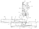
本発明の実施形態を図1〜図5を用いて説明する。図1は本発明の実施形態を示す卓上切断機の左側面図、図2は卓上切断機の正面図、図3は切断材支持時を示す正面図、図4は切断刃物部を左傾斜させた状態を示す正面図、図5はホルダの部分背面図である。
【0009】
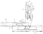
図において、ベース1の中央にターンテーブル2を水平方向へ回動自在に埋設し、ターンテーブル2の上面は、ベース1の上面と同一面となっている。ベース1及びターンテーブル2の上面には木材等の切断材20が載置される。なお、本発明においては切断材20が載置される部材(本実施形態においてはベース1とターンテーブル2)を総称してベース部という。ベース1上面の左右には、切断材20の側面を支持するフェンス3,4を固定している。フェンス3,4には、ベース1上面に対して垂直となる切断材支持面3a,4aを備えている。
【0010】
ターンテーブル2後端にはホルダシャフト5を介してホルダ6を立設し、ホルダシャフト5の軸心を、ターンテーブル2上面とほぼ一致するように位置させることで、ホルダ6はホルダシャフト5を支点として、ホルダ6に設けた長穴6aの範囲内で傾斜自在にターンテーブル2に軸支される。長穴6aにクランプレバー7を貫通させ、クランプレバー7の先端に形成したねじ部がターンテーブル2背面に形成したねじ穴部にねじ嵌合している。クランプレバー7を緩めると、ホルダ6はホルダシャフト5を支点に長穴6aの範囲内で傾斜し、クランプレバー7を締め付けると、ホルダ6はターンテーブル2とクランプレバー7間に締め付けられ、任意位置で固定される。
【0011】
ホルダ6上方にはシャフト8を介してベース1上面に対し上下揺動自在に切断刃物部9を軸支している。ホルダ6と切断刃物部9の間には、切断刃物部9を上方に付勢するスプリング10が設けられている。切断刃物部9にはモーター12から丸のこ等の切断刃物13へ動力を伝達するため、図示しないギヤなどの動力伝達機構が設けられている。14は切断刃物部9を押し下げるハンドルである。
【0012】
図2において、ホルダ6の前面には突起部6b,6cが形成され、ターンテーブル2上面後方には突起部6b,6cの移動軌跡上に位置するように、ストッパボルト15,16が直角方向にねじ嵌合している。ホルダ6が直角位置にあるときは、突起部6bがストッパボルト15の頭部に係合し、ホルダ6が左方向に45度の位置に傾斜したときに、突起部6cがストッパボルト16の頭部に係合する。
【0013】
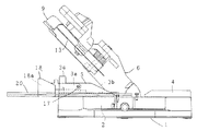
図2において、左側のフェンス3は、切断刃物部9傾斜時のスペースを確保するために、切断刃物部9の傾斜軌跡部分に傾斜状の切欠き部3bを形成している。また、フェンス3にはピン17を回動支点に移動フェンス18が回動自在に設けられている。この移動フェンス18には、フェンス3の切断材支持面3aと同一面の切断材支持面18aを有している。直角切断時には、移動フェンス18を切断刃物13側(図2において右回転)へ回動させ、図2のようにフェンス3の切欠き部3bに位置させると、広い面積で切断材20を支持することができる。傾斜切断時には、移動フェンス18を反切断刃物13側(図2において左回転)へ回動させると、図4のように、フェンス3の外方へ移動フェンス18の切断材支持面18aが位置することになり、傾斜した切断刃物部9と移動フェンス18との干渉を防いでいる。
【0014】
移動フェンス18の切断材支持面18aをフェンス3の切欠き部3bに位置させた状態において、フェンス3の左端は、移動フェンス18の切断材支持面18aの高さと同一になるよう突出部3cを形成している。
【0015】
次に、化粧長押材20を切断する方法について説明する。まず、移動フェンス18を切断刃物13側へ回動させ、フェンス3の切欠き部3bに移動フェンス18の切断材支持面18aを位置させ、ベース1上に化粧長押材20を斜めに立て掛ける。このとき、移動フェンス18の切断材支持面18aとフェンス3の突出部3cの高さが同一のため、化粧長押材20の右端上部は移動フェンス18の切断材支持面18aに支持され、左端上部はフェンス3の突出部3cに支持される。次に、ハンドル14を持ち、切断刃物部9を押し下げて切断する。
【0016】
【発明の効果】
本発明によれば、フェンス端部の切断材支持面の高さを移動フェンスの切断材支持面の高さ以上としたことにより、切断材、特に化粧長押材を切断する際、化粧長押材の上部が複数箇所で支持されるので、安定した支持ができる。
【図面の簡単な説明】
【図1】本発明の実施形態を示す卓上切断機の左側面図。
【図2】卓上切断機の正面図。
【図3】切断材支持時を示す正面図。
【図4】切断刃物部を左傾斜させた状態を示す正面図。
【図5】ホルダの部分背面図。
【図6】従来の卓上切断機の正面図。
【図7】従来の切断材支持時を示す正面図。
【符号の説明】
3,4…フェンス、3a,4a…切断材支持面、3b…切欠き部、3c…突出部、9…切断刃物部、17…ピン、18…移動フェンス、18a…切断材支持面。[0001]
BACKGROUND OF THE INVENTION
The present invention relates to a fence for supporting a cutting material in a tabletop cutting machine.
[0002]
[Prior art]
Conventionally, fences are provided at both ends on the base perpendicular to the upper surface of the base. When cutting, press the cutting material against this fence. In addition, the tabletop cutting machine includes right-angle cutting that makes the cutting blade part a right angle with respect to the base and inclined cutting that makes the cutting blade part inclined. When performing inclined cutting, since the inclined cutting blade part and the fence interfere with each other, it is necessary to make the fence partially cut out. Therefore, the area that can support the cutting material is reduced by this notch, the cutting material cannot be supported sufficiently, and the cutting position is lowered, such as the support position of the material being shifted due to this rotational force of the circle when cutting the cutting material. It was.
[0003]
For example, JP-A-9-103913 discloses a solution to this problem. As shown in FIGS. 6 and 7, a
[0004]
When cutting at right angles, the moving
[0005]
[Problems to be solved by the invention]
When cutting the decorative long pressing material 20 (also referred to as a crown molding material), the decorative long
[0006]
An object of the present invention is to eliminate the above-mentioned drawbacks of the prior art and to improve the support stability of a cutting material, particularly a decorative long pressing material.
[0007]
[Means for Solving the Problems]
The object includes a base part that supports a cutting material, a cutting blade part that is inclined in the left-right direction with respect to the base part, and a pair of fences that have a cutting material support surface and are provided on the upper surface of the base part. In a tabletop cutting machine comprising a movable moving fence having a cutting material supporting surface inside at least one fence, the height of the cutting material supporting surface at the end of the fence provided with the moving fence is set to support the cutting material of the moving fence. This is achieved by setting the height to be higher than the surface height.
[0008]
DETAILED DESCRIPTION OF THE INVENTION
An embodiment of the present invention will be described with reference to FIGS. FIG. 1 is a left side view of a tabletop cutting machine showing an embodiment of the present invention, FIG. 2 is a front view of the tabletop cutting machine, FIG. 3 is a front view showing when a cutting material is supported, and FIG. FIG. 5 is a partial rear view of the holder.
[0009]
In the figure, a
[0010]
A holder 6 is erected on the rear end of the
[0011]
A
[0012]
In FIG. 2,
[0013]
In FIG. 2, the
[0014]
In a state where the cutting
[0015]
Next, a method for cutting the decorative long
[0016]
【The invention's effect】
According to the present invention, the height of the cutting material support surface at the end of the fence is equal to or greater than the height of the cutting material support surface of the moving fence. Since the upper part is supported at a plurality of locations, stable support can be achieved.
[Brief description of the drawings]
FIG. 1 is a left side view of a tabletop cutting machine showing an embodiment of the present invention.
FIG. 2 is a front view of a tabletop cutting machine.
FIG. 3 is a front view showing when a cutting material is supported.
FIG. 4 is a front view showing a state in which a cutting blade part is inclined to the left.
FIG. 5 is a partial rear view of the holder.
FIG. 6 is a front view of a conventional tabletop cutting machine.
FIG. 7 is a front view showing when a conventional cutting material is supported.
[Explanation of symbols]
3, 4 ... Fence, 3a, 4a ... Cutting material support surface, 3b ... Notch part, 3c ... Projection part, 9 ... Cutting blade part, 17 ... Pin, 18 ... Moving fence, 18a ... Cutting material support surface.
Claims (1)
Priority Applications (1)
| Application Number | Priority Date | Filing Date | Title |
|---|---|---|---|
| JP32891099A JP3867457B2 (en) | 1999-11-19 | 1999-11-19 | Tabletop cutting machine |
Applications Claiming Priority (1)
| Application Number | Priority Date | Filing Date | Title |
|---|---|---|---|
| JP32891099A JP3867457B2 (en) | 1999-11-19 | 1999-11-19 | Tabletop cutting machine |
Publications (3)
| Publication Number | Publication Date |
|---|---|
| JP2001145901A JP2001145901A (en) | 2001-05-29 |
| JP2001145901A5 JP2001145901A5 (en) | 2005-06-23 |
| JP3867457B2 true JP3867457B2 (en) | 2007-01-10 |
Family
ID=18215467
Family Applications (1)
| Application Number | Title | Priority Date | Filing Date |
|---|---|---|---|
| JP32891099A Expired - Fee Related JP3867457B2 (en) | 1999-11-19 | 1999-11-19 | Tabletop cutting machine |
Country Status (1)
| Country | Link |
|---|---|
| JP (1) | JP3867457B2 (en) |
Families Citing this family (3)
| Publication number | Priority date | Publication date | Assignee | Title |
|---|---|---|---|---|
| JP4617152B2 (en) * | 2004-12-17 | 2011-01-19 | 株式会社マキタ | Cutting material positioning fence for cutting machine |
| JP4442514B2 (en) | 2005-05-27 | 2010-03-31 | 日立工機株式会社 | Tabletop cutting machine |
| DE202009001184U1 (en) * | 2009-01-30 | 2010-07-22 | Metabowerke Gmbh | Crosscut and miter saw |
-
1999
- 1999-11-19 JP JP32891099A patent/JP3867457B2/en not_active Expired - Fee Related
Also Published As
| Publication number | Publication date |
|---|---|
| JP2001145901A (en) | 2001-05-29 |
Similar Documents
| Publication | Publication Date | Title |
|---|---|---|
| US5564323A (en) | Circular saw unit | |
| JP2002011702A (en) | Vise device of bench circular saw | |
| US8246025B2 (en) | Vise assembly and bench circular sawing machine | |
| US7552666B2 (en) | Sawing machine | |
| US20100095823A1 (en) | Bench cutter | |
| JP2005074695A (en) | Bench slide cutter | |
| JP3867457B2 (en) | Tabletop cutting machine | |
| JP2009126059A (en) | Vice device and cutter | |
| JP2009072983A (en) | Guide fence for cutting machine, and cutting machine | |
| JP4617152B2 (en) | Cutting material positioning fence for cutting machine | |
| JP4528757B2 (en) | Portable electric cutting machine | |
| JP3925043B2 (en) | Tabletop cutting machine | |
| JP5184017B2 (en) | Positioning device for rotary table in tabletop circular saw | |
| JP4138234B2 (en) | Circular saw table lock device | |
| JPH1134002A (en) | Lower limit stopper of circular sawing machine | |
| JPH0444321Y2 (en) | ||
| JP4200471B2 (en) | Cutting machine | |
| JP4529865B2 (en) | Band saw board | |
| JP3724172B2 (en) | Tabletop cutting machine | |
| JP3674291B2 (en) | Tabletop cutting machine | |
| JPH0428722Y2 (en) | ||
| JP3834992B2 (en) | Tabletop cutting machine | |
| JPS5916173Y2 (en) | Swing device for chain chisel machine | |
| JP2002210701A (en) | Vise device of table circular saw | |
| JP4056119B2 (en) | Tabletop cutting machine |
Legal Events
| Date | Code | Title | Description |
|---|---|---|---|
| A521 | Written amendment |
Free format text: JAPANESE INTERMEDIATE CODE: A523 Effective date: 20040928 |
|
| A621 | Written request for application examination |
Free format text: JAPANESE INTERMEDIATE CODE: A621 Effective date: 20040928 |
|
| TRDD | Decision of grant or rejection written | ||
| A01 | Written decision to grant a patent or to grant a registration (utility model) |
Free format text: JAPANESE INTERMEDIATE CODE: A01 Effective date: 20060919 |
|
| A61 | First payment of annual fees (during grant procedure) |
Free format text: JAPANESE INTERMEDIATE CODE: A61 Effective date: 20061002 |
|
| R150 | Certificate of patent or registration of utility model |
Free format text: JAPANESE INTERMEDIATE CODE: R150 |
|
| FPAY | Renewal fee payment (event date is renewal date of database) |
Free format text: PAYMENT UNTIL: 20101020 Year of fee payment: 4 |
|
| FPAY | Renewal fee payment (event date is renewal date of database) |
Free format text: PAYMENT UNTIL: 20101020 Year of fee payment: 4 |
|
| FPAY | Renewal fee payment (event date is renewal date of database) |
Free format text: PAYMENT UNTIL: 20111020 Year of fee payment: 5 |
|
| FPAY | Renewal fee payment (event date is renewal date of database) |
Free format text: PAYMENT UNTIL: 20111020 Year of fee payment: 5 |
|
| FPAY | Renewal fee payment (event date is renewal date of database) |
Free format text: PAYMENT UNTIL: 20121020 Year of fee payment: 6 |
|
| FPAY | Renewal fee payment (event date is renewal date of database) |
Free format text: PAYMENT UNTIL: 20131020 Year of fee payment: 7 |
|
| FPAY | Renewal fee payment (event date is renewal date of database) |
Free format text: PAYMENT UNTIL: 20141020 Year of fee payment: 8 |
|
| LAPS | Cancellation because of no payment of annual fees |