JP3860973B2 - Method and apparatus for cooling hydroprocessing plant - Google Patents
Method and apparatus for cooling hydroprocessing plant Download PDFInfo
- Publication number
- JP3860973B2 JP3860973B2 JP2001030074A JP2001030074A JP3860973B2 JP 3860973 B2 JP3860973 B2 JP 3860973B2 JP 2001030074 A JP2001030074 A JP 2001030074A JP 2001030074 A JP2001030074 A JP 2001030074A JP 3860973 B2 JP3860973 B2 JP 3860973B2
- Authority
- JP
- Japan
- Prior art keywords
- reaction tower
- fluid
- plant
- hydrogen sulfide
- cooling
- Prior art date
- Legal status (The legal status is an assumption and is not a legal conclusion. Google has not performed a legal analysis and makes no representation as to the accuracy of the status listed.)
- Expired - Lifetime
Links
Images


Classifications
-
- C—CHEMISTRY; METALLURGY
- C10—PETROLEUM, GAS OR COKE INDUSTRIES; TECHNICAL GASES CONTAINING CARBON MONOXIDE; FUELS; LUBRICANTS; PEAT
- C10G—CRACKING HYDROCARBON OILS; PRODUCTION OF LIQUID HYDROCARBON MIXTURES, e.g. BY DESTRUCTIVE HYDROGENATION, OLIGOMERISATION, POLYMERISATION; RECOVERY OF HYDROCARBON OILS FROM OIL-SHALE, OIL-SAND, OR GASES; REFINING MIXTURES MAINLY CONSISTING OF HYDROCARBONS; REFORMING OF NAPHTHA; MINERAL WAXES
- C10G45/00—Refining of hydrocarbon oils using hydrogen or hydrogen-generating compounds
- C10G45/02—Refining of hydrocarbon oils using hydrogen or hydrogen-generating compounds to eliminate hetero atoms without changing the skeleton of the hydrocarbon involved and without cracking into lower boiling hydrocarbons; Hydrofinishing
-
- B—PERFORMING OPERATIONS; TRANSPORTING
- B01—PHYSICAL OR CHEMICAL PROCESSES OR APPARATUS IN GENERAL
- B01D—SEPARATION
- B01D53/00—Separation of gases or vapours; Recovering vapours of volatile solvents from gases; Chemical or biological purification of waste gases, e.g. engine exhaust gases, smoke, fumes, flue gases, aerosols
- B01D53/14—Separation of gases or vapours; Recovering vapours of volatile solvents from gases; Chemical or biological purification of waste gases, e.g. engine exhaust gases, smoke, fumes, flue gases, aerosols by absorption
- B01D53/1456—Removing acid components
- B01D53/1468—Removing hydrogen sulfide
-
- B—PERFORMING OPERATIONS; TRANSPORTING
- B01—PHYSICAL OR CHEMICAL PROCESSES OR APPARATUS IN GENERAL
- B01J—CHEMICAL OR PHYSICAL PROCESSES, e.g. CATALYSIS OR COLLOID CHEMISTRY; THEIR RELEVANT APPARATUS
- B01J2219/00—Chemical, physical or physico-chemical processes in general; Their relevant apparatus
- B01J2219/00002—Chemical plants
- B01J2219/00004—Scale aspects
- B01J2219/00006—Large-scale industrial plants
Description
【0001】
【発明の属する技術分野】
本発明は、水素化処理プラントの冷却方法および冷却装置に関する。
【0002】
【背景技術】
一般に、水素化処理プラントは、硫黄を水素化して硫化水素を生成する反応塔、およびこの反応塔で生成された硫化水素を吸収する硫化水素吸収塔を有する脱硫セクションと、前記硫化水素吸収塔で硫化水素を吸収させるための液体を循環させる硫化水素吸収セクションとを備えている。
【0003】
この水素化処理プラントでは、触媒交換等のため、運転を停止する際に、反応塔をおよそ400℃から40℃まで急速に冷却しなければならない。
従来から、水素化処理プラントを冷却するための冷却装置として空冷熱交換器が利用されている。この空冷熱交換器は、反応塔より下流側に配置されライン中を循環するリサイクルガスを除熱する構造である。
【0004】
【発明が解決しようとする課題】
しかしながら、この従来例では、水素化処理プラント中の反応塔を400℃から40℃まで冷却するのに、5〜7日程度の日数を必要とし、しかも、冷却に要する時間は外気温度に左右されるという問題点がある。
この問題点を解決するため、空冷熱交換器に水を噴霧し、空冷熱交換器全体を冷却する方法(改良案1)、脱硫セクション中に配置された熱交換器にバイパスを設け、このバイパスを通った冷たいリサイクルガスを直接反応塔に導入する方法(改良案2)、反応塔の上部より液体窒素を注入し、リサイクルガスの温度を下げる方法(改良案3)、反応塔の上部より液体プロパンを注入し、リサイクルガスの温度を下げる方法(改良案4)、加熱炉の上部へ散水し、加熱炉全体を冷却する方法(改良案5)、硫化水素吸収セクションに特殊な冷却ユニットを設けることで、循環液体を冷却し、冷却された循環液体が硫化水素吸収塔を通る際に循環ガスを冷却し、この冷却された循環ガスにより反応塔全体を冷却する方法(改良案6)等が開発されている。
【0005】
改良案1では、水噴霧によって空冷熱交換器のモータ部、軸受け部等が損傷するため、モータ部等の損傷防止用カバーや水滴落下防止用桶の設置が不可欠となる。しかも、十分な冷却を行うには、多量の水が必要になるという問題もある。
改良案2では、バイパスの設置場所が高温高圧な脱硫セクションであるから、ラインを構成するパイプ等には高級材質が必要となり、かつ、厚肉の材料を使用しなければならないので、バイパス設置費用が高額なものとなるという問題がある。しかも、バイパスを設けるのみでは、得られる冷却加速効果は十分であるとはいえない。
【0006】
改良案3では、十分な冷却を行うために、単価の高い液体窒素が大量に必要となるので、ランニングコストが過大となるという問題がある。
改良案4では、冷却後、気化したプロパンガスを窒素ガスでフレアーに追い出す作業が必要となる。
【0007】
改良案5では、加熱炉内が水浸しとなるので、スタートアップ時に余分な時間が必要となる。さらに、加熱炉のバーナ内に水が浸入しないような対策が必要となる。しかも、加熱炉全体を水で冷却する方法であるので、冷却効率が低く、十分な冷却を行うには、多量の水が必要となる。
改良案6では、改良案1〜5と比べて非常に効率的な冷却が可能となるが、特殊な冷却ユニットを必要とするため、その導入コストがかかるとともに、別途冷却ユニットの設置作業を行う必要がある等、いくつかの問題点を残している。
【0008】
本発明の目的は、特殊な冷却装置を必要としなくとも、効率的かつ速やかに水素化処理プラントの冷却が可能な水素化処理プラントの冷却方法および冷却装置を提供することにある。
【0009】
【課題を解決するための手段】
これまで、水素化処理時に高温下にさらされた反応塔が焼き戻し脆化を起こし、その結果強度が低下した反応塔を高圧下にさらすことによる破損等を防止するために、水素化処理プラント停止時の圧力は、ほぼ大気圧に近いような低圧である所定値以下に保持されていた。しかしながら、反応塔に使用される材料の進歩により、系内の圧力を多少高めに保持することが可能になってきている。
【0010】
それにもかかわらず、系内の圧力を従来よりも高く保持して、水素化処理プラントを速やかに冷却する試みは、現在までのところ十分に検討されているとはいえない。
そこで、本発明は、水素化処理プラント停止時において、系内の温度との関係で系内の圧力を可能な限り高く保持するとともに、系内の流体の流量を高く保つことで、前記目的を達成しようとするものである。
【0011】
具体的には、本発明に係る水素化処理プラントの冷却方法は、被処理液の加熱炉、硫黄を水素化して硫化水素を生成する反応塔、この反応塔で生成された硫化水素を吸収する硫化水素吸収塔、およびこの硫化水素吸収塔側からの流体を前記反応塔側に圧縮して送るコンプレッサを有する脱硫セクションを備える水素化処理プラントを停止するに際して、前記反応塔内を速やかに冷却する水素化処理プラントの冷却方法であって、前記脱硫セクションでは、被処理液の供給停止後、水素化処理プラント系内の圧力を反応塔を構成する材料の焼き戻し脆化および系内での機械的な熱膨張の差によるガスの漏洩が生じない圧力に向けて徐々に減圧するとともに、前記コンプレッサを略最大回転させ、かつ、前記加熱炉のバーナを完全消火し、前記反応塔に触媒床を設け、さらに、前記コンプレッサから反応塔側に流体を送る流路に、前記反応塔から硫化水素吸収塔に向かう流体と熱交換された高温流体が流れる高温流体流路と、熱交換されない低温流体が通る低温流体流路とを設け、この低温流体流路を前記触媒床に接続し、前記触媒床に前記低温流体を流すことで前記反応塔を冷却することを特徴とする。
【0012】
ここで、プラントを停止する際の系内の圧力は、冷却効率を高めるためには、高ければ高いほどよいが、あまりに高すぎると反応塔を構成する材料の焼き戻し脆化による反応塔の事故が生じる虞があるとともに、機械的な熱膨張の差によるガスの漏洩の虞がある。したがって、冷却効率、焼き戻し脆化およびガス漏洩の兼ね合いを考慮して、系内の温度に対応した最適な系内の圧力を設定することとなる。具体的な圧力としては、運転時の圧力の70%以上の圧力であることが好ましい。
【0013】
この発明によれば、系内の圧力を反応塔を構成する材料の焼き戻し脆化および系内での機械的な熱膨張の差によるガスの漏洩が生じない圧力に維持しつつ、コンプレッサを略最大回転させているから、系内のガス流量が一定量以上に保たれるとともに、流速が略最大に保たれることとなる。しかも、この状態でバーナを完全消火しているから、比較的温度の低い流体が系内を速やかに流れ、結果として反応塔内を迅速に冷却できる。
【0014】
以上において、前記脱硫セクションにガス放出弁を設け、このガス放出弁を開閉することにより、前記プラント系内の圧力を調節することが好ましい。
このようにガス放出弁を設けることにより、系内の圧力調節が容易に行えるようになる。
【0015】
また、前記加熱炉に開口面積調整可能な空気流通口を設けるとともに、空気の導入または排出を行うファンを設け、前記加熱炉のバーナ消火後、前記空気流通口の開口面積を最大にするとともに、前記ファンを略最大回転数で運転することことが好ましい。
ここで、空気流通口としては、加熱炉内に空気を導入する空気導入口、空気を排出する空気排出口のどちらを採用してもよい。また、空気の導排出を行うファンとしては、空気導入口の場合には、排気側に設ける排気ファンを採用すればよく、空気排出口の場合には、供気側に設ける押し込みファンを採用すればよい。
【0016】
この発明によれば、加熱炉に開口面積調整可能な空気流通口を設けるとともに、空気の導入または排出を行うファンを設け、空気流通口の開口面積を最大にし、かつ、ファンを略最大回転で運転している。
したがって、最も高温である加熱炉を迅速かつ効率的に冷却することが可能となり、結果として、プラント系内を速やかに冷却することができる。
【0017】
さらに、前記反応塔の下流側の流体の熱と、前記加熱炉の上流側に供給される流体の熱とを熱交換させる1以上の熱交換器を設けるとともに、これらの熱交換器をバイパスするバイパス流路を開閉可能に設け、かつ前記熱交換器入り口に絞り弁を開閉可能に設け、処理運転時に前記バイパス流路を閉止し、プラント停止操作時に前記バイパス流路を開放するとともに、前記絞り弁を調整することが好ましい。
【0018】
すなわち、通常運転時は、可能な限り熱効率を高めるために、積極的に流体の熱交換を行うこととなるが、プラント停止時には、熱交換して冷えた流体を再び高温にする必要がなくなるだけでなく、熱交換をすることで、系内の冷却効率が低下することとなる。
そこで、この発明のように熱交換器をバイパスするバイパス流路および熱交換器入り口に絞り弁を設けることで、冷却された流体が熱交換で再び高温になることを防止するとともに、この冷却された流体を系内に循環させることで、プラント系内の冷却効率の向上を図ることができる。
【0020】
なお、低温流体流路は、必ずしも全ての触媒床に接続されている必要はなく、運転時のプラントの温度、冷却時の系内の圧力等を考慮して適宜低温流体を流す触媒床を選択すればよい。
また、複数の反応塔を有するプラントの場合には、各反応塔を連結する配管にも低温流体流路を連結することが好ましい。反応塔間の配管に連結し、この部分から低温流体を流すことで、さらに冷却効率を向上することができる。
【0021】
この発明によれば、熱交換器で熱交換されない低温流体を、反応塔の各触媒床に直接導入しているから、塔頂からのみ低温流体を導入する場合よりも、効率的な反応塔の冷却が可能となる。すなわち、塔頂のみから低温流体を導入する場合には、塔底に流れるにつれ流体の温度が上昇し、塔底近傍の触媒床の冷却効率は著しく低下することとなるが、各触媒床に直接低温流体を導入することで、均一に冷却することができ、全体として冷却効率が高まる。
【0022】
また、前記反応塔の下流側に、開口面積調整可能な空気流通口を有する空冷熱交換器を少なくとも1つ設け、この空冷熱交換器を全数起動させるとともに、前記空気流通口を全開させることが好ましい。
ここで、空気流通口としては、空気導入口、空気排出口のどちらを採用することもできる。
この発明によれば、さらに、反応塔の下流側に少なくとも1つの空冷熱交換器を設け、この冷却器を全数起動させるとともに、空気流通口を全開にしているから、より一層プラント系内の冷却効率を高めることができる。
【0023】
さらに、前記硫化水素吸収塔をバイパスするバイパス流路を設け、処理運転時に前記バイパス流路を閉止し、プラント停止操作時に前記バイパス流路を開放することが好ましい。
本発明によれば、硫化水素塔をバイパスするバイパス流路を設けているから、循環ガス中の硫化水素濃度が低下した後、直ちにバイパス流路の開放を行うことで、硫化水素塔からプラント系内への熱量の流入を抑えることができ、結果として、冷却効率を高めることができる。
【0024】
本発明に係る水素化処理プラントの冷却装置は、被処理液の加熱炉、硫黄を水素化して硫化水素を生成する反応塔、この反応塔で生成された硫化水素を吸収する硫化水素吸収塔、およびこの硫化水素吸収塔側からの流体を前記反応塔側に圧縮して送るコンプレッサを有する脱硫セクションを備える水素化処理プラントを停止するに際して、前記反応塔を速やかに冷却する水素化処理プラントの冷却装置であって、前記脱硫セクションにガス放出弁を設け、さらに前記加熱炉に開口面積調整可能な空気流通口を設けるとともに、空気の導入または排出を行うファンを設け、かつ、前記反応塔の下流側の流体の熱と、前記加熱炉の上流側に供給される流体の熱とを熱交換させる1以上の熱交換器を設けるとともに、これらの熱交換器をバイパスする開閉可能なバイパス流路および熱交換器入り口に絞り弁を設け、前記反応塔に触媒床を設け、さらに前記コンプレッサから反応塔側に流体を送る流路に、前記反応塔から硫化水素吸収塔に向かう流体と熱交換された高温流体が流れる高温流体流路と、熱交換されない低温流体が通る低温流体流路とを設け、この低温流体流路を前記触媒床および反応塔に接続し、かつ、前記反応塔の下流側に、開口面積調整可能な空気流通口を有する空冷熱交換器を少なくとも1つ設け、さらに、前記硫化水素吸収塔にバイパス流路を設けたことを特徴とする。
【0025】
この発明によれば、脱硫セクションにガス放出弁を設けているから、脱硫セクションの圧力調整を容易に行うことができる。
また、加熱炉に開口面積調整可能な空気流通口を設けるとともに、空気の導入または排出を行うファンを設けているから、停止時に加熱炉内に空気を流すことができ、最も高温の加熱炉を効率よく冷却することができる。
さらに、熱交換器をバイパスするバイパス流路を設けているから、冷却された流体が熱交換で再び高温になることを防止するとともに、この冷却された流体を系内に循環させることで、プラント系内の冷却効率の向上を図ることができる。
【0027】
この発明によれば、低温流体流路を設け、これを触媒床に接続しているから、熱交換器で熱交換されない低温流体を、反応塔の各触媒床に直接導入でき、これにより塔頂からのみ低温流体を導入する場合よりも、効率的な反応塔の冷却が可能となる。
また、反応塔の下流側に少なくとも1つの空冷熱交換器を設けているから、より一層プラント系内の冷却効率を高めることができる。
さらに、硫化水素吸収塔にバイパス流路を設けることにより、系内への余剰熱量の持ち込みを抑えることで、冷却効果を一層高めることができる。
【0028】
【発明の実施の形態】
以下、本発明の実施の一形態を図面に基づいて説明する。
[1]水素化処理プラントの構成
図1から図3には、本発明の一実施形態に係る水素化処理プラントが示されている。
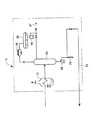
水素化処理プラントは、被処理液体である原料油の水素化脱硫プラントであり、図1に示されるように、脱硫セクション1、硫化水素吸収セクション3、および蒸留セクション5を備えて構成されている。
【0029】
脱硫セクション1は、サージタンク11、加熱炉12、原料油移送ポンプ13、第1反応塔14、第2反応塔15、高温分離槽16、空冷熱交換器17、低温分離槽18、硫化水素吸収塔19、第1〜第3熱交換器20A〜20C、コンプレッサ21、緊急脱圧および圧力調整のためのガス放出弁22、第1〜第4バイパス流路23A〜23D、コンプレッサ21から反応塔14、15側に流体を送る流路24、蒸留セクションで精製された脱硫油の製品取出し流路25、この製品取出し流路25から分岐されプラント運転開始時および停止時の所定時間蒸留セクション5側からの流体をサージタンク11に返送、循環させるためにバルブ25Bで開閉される脱硫油戻し流路25A、系内へ水素を供給する水素供給装置26、第1〜第3熱交換器20A〜20Cの流入側に設けられた弁27A〜27C、および系内の液体成分を抜き出すためのドレインバルブ28等を備えている。
【0030】
サージタンク11には、水素化処理プラント内に供給する被処理液体である原料油が貯留されており、ここから原料油移送ポンプ13により、系内に原料油が送られることとなる。
加熱炉12は、供給された原料油を所定温度まで加熱する装置であり、その内部にはメインバーナ12Aおよびパイロットバーナ12Bが設けられている。また、加熱炉12の吸気側には、空気流量の調節可能な空気流通口である空気導入口12Cが設けられるとともに、排気側には、加熱炉12内部に供給された空気を吸引して排出するためのファンである吸引ファン12Dが設置されている。
【0031】
第1、第2反応塔14、15は、加熱された流体が塔頂部から塔底部に向かって流れる間に、それらの内部に収納された触媒により原料油の硫黄分を水素と反応させて硫化水素を生成させる装置である。ここで、各反応塔14、15は、内部にそれぞれ複数段、例えば3段の触媒床14A〜14C、15A〜15Cを備えており、各触媒床14A〜14C、15A〜15Cそれぞれで、脱硫反応が進行することとなる。
高温分離槽16は、第2反応塔15から送られて来る高温の流体を高温液体成分(油成分)と高温ガス成分とに分離する装置である。ここで分離された高温液体成分は、塔底から排出されて蒸留セクション5に送られ、一方、高温ガス成分は、塔頂から排出されて空冷熱交換器17へ送られる。
【0032】
空冷熱交換器17は、前述の高温分離槽16で分離された高温ガス成分を空気により冷却し、さらに低温液体成分を凝縮させる装置であり、その上部ないし底部には、開口面積調整可能なルーバー(空気流通口)17Aおよびファン17Bが設けられている。ここで、空冷熱交換器17は、図示は省略しているが、複数、例えば8台設けられ、通常運転時はその一部を起動して流体を冷却している。なお、空冷熱交換器17の上流側から、流体中の析出物を洗浄するための洗浄水が必要に応じて供給されている。
【0033】
低温分離槽18は、前述の空冷熱交換器17で冷却された低温液体成分(油成分)と低温ガス成分とを分離する装置である。ここで、分離された低温液体成分は、低温分離槽18の下部から排出されて前述の高温液体成分と合流した後、蒸留セクション5に送られる。一方、低温ガス成分は、低温分離槽18の上部から排出されて後述する硫化水素吸収塔19へ送られる。
【0034】
硫化水素吸収塔19は、低温分離槽18で分離された低温ガス成分中の硫化水素を吸収する装置であり、その内部には硫化水素を吸収するためのアミン水溶液が流れている。
第1〜第3熱交換器20A〜20Cは、通常運転時には、高温流体と低温流体との熱交換を行い、プラント系内の熱効率を高める装置である。
【0035】
すなわち、第1熱交換器20Aは、サージタンク11から供給される低温の原料油、およびコンプレッサ21の吐出側に接続された流路24からのリサイクルガスの混合流体と、第2反応塔15から流出して来る高温流体とを熱交換して、原料油および水素等を加温するための装置である。第2熱交換器20Bは、高温分離槽16の塔頂から排出される高温ガス成分と硫化水素吸収塔19およびコンプレッサ21を通じた後の低温(リサイクル)ガス成分(低温流体)とを熱交換して低温ガス成分を加温し高温流体とする装置である。第3熱交換器は、サージタンク11側から供給される原料油等と蒸留セクション5から送出される製品取出し流路25を流れる脱硫油との熱交換を行う装置である。
【0036】
コンプレッサ21は、硫化水素吸収塔19を通過してくる気体成分の一部を流路24を通じて加熱炉12および各反応塔14、15へ圧縮して移送する装置である。
第1〜第4バイパス流路23A〜23Dは、前述の熱交換器20A〜20Cおよび硫化水素吸収塔19をバイパスするための流路であり、通常運転時には、閉止されているが、プラント停止操作時には開放される流路である。
【0037】
第1バイパス流路23Aは、前述の第1熱交換器20Aをバイパスするための流路であり、開閉可能な弁を備えている。プラント冷却時には、この弁を開放するとともに、第1熱交換器20A入り口の絞り弁27Aを絞ることで、第1熱交換器20Aにおける第2反応塔15から排出される流体と加熱炉12に流入する流体との熱交換を、通常運転時の約30%まで減少させ、これにより通常運転時よりも低温の流体が加熱炉12側に送られることとなる。
【0038】
第2バイパス流路23Bは、前述の第2熱交換器20Bをバイパスするための流路であり、第1バイパス流路23A同様開閉可能な弁を備えている。前述同様、この弁を停止時に開放するとともに、第2熱交換器20B入り口の絞り弁27Bを絞ることで、第2熱交換器20Bにおける高温分離槽16から排出される高温ガス成分とコンプレッサ21により圧縮・移送される流体との熱交換を40%にまで減少させ、低温分離槽18から排出された低温ガス成分(低温流体)が、通常運転時よりも低い温度で加熱炉12側に送られることとなる。
【0039】
第3バイパス流路23Cは、硫化水素吸収塔19をバイパスするための流路であり、開閉可能な弁を備えている。前述同様、この弁を開放することで、硫化水素吸収セクション3側との熱交換率を極力減少させることとなる。第4バイパス流路23Dは、前述の第3熱交換器20Cをバイパスするための流路であり、開閉可能な弁を備えている。前述同様この弁を停止時に開放するとともに、第3熱交換器20C入り口の絞り弁27Cを絞ることで、第3熱交換器20Cにおける比較的高温の脱硫後の製品との熱交換を減少させ、低温の流体が加熱炉12側に送られることとなる。
【0040】
なお、絞り弁27A〜27Cを完全閉止せずに、絞った状態で一部開いておくのは、熱交換器20A〜20Cにおける熱交換を全く行わないと、運転停止操作時の初期段階では、各熱交換器20A〜20Cが過熱する可能性があるためであり、その虞がない場合には、完全閉止しても問題はない。
【0041】
硫化水素吸収セクション3は、一般的な、硫化水素吸収塔19内に前述のアミン水溶液を接触させるセクションであり、アミン水溶液と接触させ低温分離槽からのガス(リサイクルガス)中の硫化水素を吸収させるセクションである。
蒸留セクション5は、図2に示されるように、前述の高温分離槽16および低温分離槽18で分離された液体成分を再び加熱する加熱炉52と、加熱された液体成分を蒸留する蒸留塔53と、蒸留後に蒸留塔53の塔頂から排出される流体を凝縮させる空冷熱交換器54と、この空冷熱交換器54で冷却された流体を気液の両成分に分離する分離槽55と、この分離槽55で分離された液体成分を製品流路57へ送るポンプ56と、蒸留後に塔底から排出される流体を移送するポンプ58と、を備えている。
【0042】
ポンプ58により送り出された流体は、前述の製品取出し流路25を通じて、脱硫セクション1側に送られる。
なお、加熱炉52、空冷熱交換器54、分離槽55は、それぞれ前述の加熱炉12、空冷熱交換器17、低温分離槽18と同等のものである。
【0043】
[2]水素化処理プラントによる原料油の脱硫方法
上述のように構成された水素化処理プラントを用いての原料油の水素化処理操作は、次のように行う。
まず、プラント運転のため、サージタンク11に原料油を供給し、さらに、水素供給装置26を作動させる。
【0044】
原料油移送ポンプ13によりサージタンク11内の原料油が第3熱交換器20Cおよび第1熱交換器20Aを介して加熱炉12に送られ、さらに、水素供給装置26により水素が第2熱交換器20B、第1熱交換器20Aをこの順に介して加熱炉12に送られる。
原料油及び水素は加熱炉12で加熱された後、第1反応塔14および第2反応塔15に送られる。これらの各反応塔14、15では、原料油中の硫黄成分が水素と反応して硫化水素が生成される。
【0045】
この硫化水素と反応塔14、15で反応されない水素とを含む高温の流体は、第1熱交換器20Aを通って高温分離槽16に送られ、この高温分離槽16で、高温液体成分(油成分)と高温ガス成分とに分離される。さらに、分離された高温ガス成分は、第2熱交換器20Bを介した後、空冷熱交換器17で冷却され、低温分離槽18に送られ、この低温分離槽18でさらに低温液体成分(油成分)と低温ガス成分とに再分離される。
【0046】
低温分離槽18から硫化水素吸収塔19へ低温ガス成分が送られ、この硫化水素吸収塔19では、硫化水素吸収セクション3から送られるアミン水溶液に、低温ガス成分中に存在する硫化水素が吸収される。硫化水素吸収塔19で吸収されない硫化水素および水素からなる流体は、コンプレッサ21により、その一部が各熱交換器20B、20Aをこの順に介した後に高温流体流路24Aを通って加熱炉12に送られる。
【0047】
一方、残りは低温流体流路24Bを通過して、各反応塔14、15内の温度が所定温度以上に上昇した場合に、温度制御弁29が開放して、各反応塔14、15内に供給され、反応塔14、15内の温度を低下させるようになっている。このように、水素は脱硫セクション1中をリサイクルし、消費されるので、水素供給装置26では水素供給量を適宜調整することとなる。
【0048】
一方、高温分離槽16で分離された高温液体成分および低温分離槽18で分離された低温液体成分とからなる流体は、蒸留セクション5に送られ、蒸留による精製が行われた後、製品として回収される。ここで、運転開始時および停止時の一定時間の間、製品の一部が脱硫油戻し流路25Aを通じて脱硫セクション1に戻される。
【0049】
すなわち、脱硫セクション1からの流体は、蒸留セクション5に導入され、図2に示されるように、まず加熱炉52で加熱された後、蒸留塔53内に供給される。この蒸留塔53内で蒸留・精製された流体の一部は、塔頂から排出された後、空冷熱交換器54を介して分離槽55でガス成分と液体成分に分離され、液体成分は製品流路57から製品として回収される。
【0050】
この際、一部の製品は、ポンプ56により再び蒸留塔53へ還流されることとなる。一方、塔底から排出される流体は、ポンプ58により製品取出し流路25へ送られる。製品取出し流路25を通過した流体は、脱硫セクション1側に送られ、通常運転時は、第3熱交換器20Cを介して製品として回収される(図1参照)。
【0051】
[3]水素化処理プラントの冷却方法
次に、[2]で説明した水素化処理後に、プラントを停止する際の系内の冷却方法について説明する。
(1)プラント系内への新しい原料油の供給を停止した後、コンプレッサ21を最大回転数まで上げ、ガスの循環流量を最大に設定する。
(2)ガス放出弁22の開き具合を調整して、系内の圧力を反応塔を構成する材料の焼き戻し脆化および系内での機械的な熱膨張の差によるガスの漏洩が生じない圧力、すなわち、水素化処理時の約70%に向けて徐々に下げる(運転圧:約18.8MPa、調整後:約13MPa)(図3(B)参照)。この際のプラント系内の温度は、約300〜350℃である。
なお、図3(B)は、縦軸にプラント系内の圧力を、横軸に時間をとり圧力の時間変化を表したグラフであり、本発明の方法では、従来法よりもプラント系内の圧力が高く維持されていることがわかる。
【0052】
(3)加熱炉12のメインバーナ12Aおよびパイロットバーナ12Bを完全に消火する。
(4)加熱炉12の空気導入口12Cを全開にするとともに、吸引ファン12Dを最大回転数に設定し、加熱炉12内の空気の流れを最大にし、加熱炉12内を積極的に空冷する。
(5)第3熱交換器20Cの第4バイパス流路23Dを全開するとともに、熱交換器20Cの製品取出し流路25側の絞り弁27Cを絞り込み、熱交換を少なくして流体の温度を下げる。
【0053】
(6)第1熱交換器20Aの第1バイパス流路23Aを全開するとともに、熱交換器20Aへの流入側の絞り弁27Aを水素化処理時の30%まで絞り込み、熱交換を少なくして流体の温度を下げる。
(7)第1反応塔14および第2反応塔15の各触媒床14A〜14C、15A〜15Cに、それぞれ可能な限りの量の低温流体を流す。
(8)第2熱交換器20Bの第2バイパス流路23Bを全開するとともに、熱交換器20Bへコンプレッサ21から流入してくる側の絞り弁27Bを水素化処理時の40%まで絞り込み、熱交換を少なくして流体の温度を下げる。
【0054】
(9)第2熱交換器20Bの後流側に設けられた空冷熱交換器17を全数起動させるとともに、空気導入口17Aを全開し、ファン17Bを最大回転数に設定して流体の冷却効率を可能な限り上昇させる。
(10)約24時間系内を徐々に減圧した後、ガス放出弁を開放し、系内の圧力を水素化処理時の約70%(約13MPa)に向けてさらに下げる(図3(B)参照)。
この際のプラント系内の温度は、約150℃〜200℃である。
【0055】
(11)第3バイパス流路23Cを全開して、硫化水素吸収塔19側へ低温ガス成分が流入するのを抑える。
(12)硫化水素吸収セクション3におけるアミン水溶液の温度が低下した後、硫化水素吸収セクションの高圧アミン水溶液ポンプ38を停止させる。
上記(1)〜(12)の手順は、冷却可能な限りにおいて、順序を入れ替えることも可能である。また、上記(1)〜(12)の番号は、図3(A)中に付された番号と対応している。
【0056】
なお、上記操作中において、系内に残留する液体成分は、プラント系内がある所定温度以下(例えば、100℃以下)になるまでは、循環させておくが、その後は、ドレインバルブ28(図1、図2参照)から適宜抜き出すこととなる。
【0057】
上述のような本実施形態によれば、次のような効果が得られる。
(1)系内の圧力を運転時の70%以上に維持しつつ、コンプレッサ21を略最大回転させているから、系内のガス流量が一定量以上に保たれるとともに、流速が略最大に保たれることとなる。しかも、この状態で加熱炉12の各バーナ12A、12Bを完全消火しているから、比較的温度の低い流体が系内を速やかに流れ、結果として各反応塔14、15内を迅速に冷却できる。
【0058】
すなわち、縦軸に反応塔の温度を、横軸に冷却時間をとったグラフである図3(A)に示されるように、従来の冷却法と比較して冷却時間が非常に短縮されていることがわかる。特に、冷却ドライビングフォースの小さくなっている100℃からの冷却時間においてその速度の差が顕著であり、最終的に50℃に到達するまでの時間は、本発明の冷却方法の方が、約45時間も速いことがわかる。
(2)漸次減圧して系内の圧力を通常運転時の約70%に保持することで、各反応塔14、15内がより高温である初期段階の冷却効率を上昇させることができる。
【0059】
(3)加熱炉12の吸気側に開口面積調整可能な空気導入口12Cを設けるとともに、排気側に吸引ファン12Dを設け、空気導入口12Cの開口面積を最大にし、かつ、吸引ファン12Dを略最大回転で運転している。したがって、最も高温である加熱炉12に空気を最大限に供給して迅速かつ効率的に冷却することが可能となり、結果として、プラント系内を速やかに冷却することができる。
(4)各熱交換器20A〜20Cをバイパスする第1〜第3バイパス流路23A、23B、23Dを設けることで、冷却された流体が熱交換で再び高温になることを防止するとともに、この冷却された流体を系内に循環させることで、プラント系内の冷却効率の向上を図ることができる。
【0060】
(5)第2熱交換器20Bで熱交換されない低温流体を、各反応塔14、15の各触媒床14A〜14C、15A〜15C、および各反応塔14、15間の配管に直接導入しているから、塔頂からのみ低温流体を導入する場合よりも、効率的に各反応塔14、15を冷却することができる。すなわち、塔頂のみから低温流体を導入する場合には、塔底に流れるにつれ流体の温度が上昇し、塔底近傍の触媒床の冷却効率は著しく低下することとなるが、各触媒床14A〜14C、15A〜15C、および各反応塔14、15間の配管に直接低温流体を導入することで、均一に冷却することができ、全体として冷却効率が高まる。
【0061】
(6)第2反応塔15の下流側に複数の空冷熱交換器17を設け、この冷却器17を全数起動させるとともに、空気導入口17Aを全開にし、かつファン17Bを最大回転数で作動させているから、より一層プラント系内の冷却効率を高めることができる。
(7)ガス放出弁22を設けているから、プラント系内の圧力調整を容易に行うことができる。
【0062】
なお、本発明は前記実施形態に限定されるものではなく、本発明の目的を達成できる範囲での変形、改良は、本発明に含まれるものである。例えば、前記実施形態では、冷却時のプラント系内の圧力を、通常時の約70%としたが、これに限定されるものではない。すなわち、反応塔を構成する材料の焼き戻し脆化および系内での機械的な熱膨張の差によるガスの漏洩が生じない圧力であれば任意であり、反応塔の構成材料、水素化処理時の系内の温度等を考慮して、適宜調整することができる。
【0063】
前記実施形態では、第1熱交換器20A入り口の絞り弁27Aを水素化処理時の30%まで絞り込むとともに、第2熱交換器20B入り口の絞り弁27Bを水素化処理時の40%まで絞り込んでいたが、これに限定されず、運転時のプラントの温度、冷却時の系内の圧力、機械的な熱膨張の差によるガスの漏洩等に応じて適宜調整することができる。
また、第1、第2反応塔14、15の全ての触媒床14A〜14C、15A〜15Cに低温流体を導入していたが、これに限られず、任意の触媒床に低温流体を導入してもよい。
【0064】
前記実施形態では、第1、第2反応塔14、15を用いていたが、これに限定されず、一つの反応塔のみ用いてもよく、三つ以上の反応塔を用いることもできる。また、反応塔の数に対応して、その他の装置の数も適宜増減可能である。
さらに、コンプレッサ21の出力、反応塔12の吸引ファン12Dの回転数、空冷熱交換器17のファン17Bの回転数は、運転時のプラントの温度、冷却時の系内の圧力等に応じて適宜調整することができる。
そして、反応塔12の空気導入口12Cの開口面積、空冷熱交換器17の空気導入口17Aの開口面積も運転時のプラントの温度、冷却時の系内の圧力等に応じて適宜調整することができる。
【0065】
また、水素化処理プラントとして、水素化脱硫プラントとしていたが、これに限定されず、ハイドロクラッキング、水素化分解プラントとすることもできる。その他、本発明を実施する際の具体的な構造および形状等は、本発明の目的を達成できる範囲内で他の構造等としてもよい。
【0066】
【発明の効果】
本発明によれば、系内の圧力を反応塔を構成する材料の焼き戻し脆化および系内での機械的な熱膨張の差によるガスの漏洩が生じない圧力に維持しつつ、コンプレッサを略最大回転させているから、系内のガス流量が一定量以上に保たれるとともに、流速が略最大に保たれることとなる。しかも、この状態でバーナを完全消火しているから、比較的温度の低い流体が系内を速やかに流れ、結果として反応塔内を迅速に冷却できるという効果がある。
【図面の簡単な説明】
【図1】本発明の一実施形態に係る水素化処理プラント(脱硫セクション)を示す概略構成図である。
【図2】図1の実施形態における蒸留セクションを示す概略構成図である。
【図3】本発明に係るプラント冷却方法の冷却時間および系内圧力を従来法と比較したグラフである。
【符号の説明】
1 脱硫セクション
12 加熱炉
12A、12B バーナ
12C 空気流通口としての空気導入口
12D ファンとしての吸引ファン
20A〜20C 熱交換器
23A、23B、23C、23D バイパス流路
27A、27B、27C 絞り弁
14、15 反応塔
14A〜14C 触媒床
15A〜15C 触媒床
17 空冷熱交換器
17A 空気流通口としてのルーバー
19 硫化水素吸収塔
21 コンプレッサ
22 ガス放出弁
24 流路
24A 高温流体流路
24B 低温流体流路 [0001]
BACKGROUND OF THE INVENTION
The present invention relates to a cooling method and a cooling apparatus for a hydroprocessing plant.
[0002]
[Background]
Generally, a hydroprocessing plant includes a reaction tower that hydrogenates sulfur to produce hydrogen sulfide, a desulfurization section that has a hydrogen sulfide absorption tower that absorbs hydrogen sulfide produced in the reaction tower, and the hydrogen sulfide absorption tower. A hydrogen sulfide absorption section for circulating a liquid for absorbing hydrogen sulfide.
[0003]
In this hydroprocessing plant, when the operation is stopped due to catalyst exchange or the like, the reaction tower must be rapidly cooled from about 400 ° C. to 40 ° C.
Conventionally, an air-cooled heat exchanger has been used as a cooling device for cooling a hydroprocessing plant. This air-cooled heat exchanger is arranged downstream of the reaction tower and has a structure for removing heat from the recycle gas circulating in the line.
[0004]
[Problems to be solved by the invention]
However, in this conventional example, it takes about 5 to 7 days to cool the reaction tower in the hydroprocessing plant from 400 ° C. to 40 ° C., and the time required for cooling depends on the outside air temperature. There is a problem that.
In order to solve this problem, water is sprayed on the air-cooled heat exchanger to cool the entire air-cooled heat exchanger (improved plan 1), and a bypass is provided in the heat exchanger disposed in the desulfurization section. A method of introducing cold recycle gas that has passed through the reactor directly (improved plan 2), a method of injecting liquid nitrogen from the upper part of the reaction tower to lower the temperature of the recycled gas (improved plan 3), and a liquid from the upper part of the reactor Injecting propane and lowering the temperature of the recycle gas (improved plan 4), spraying water to the top of the heating furnace and cooling the entire heating furnace (improved plan 5), and installing a special cooling unit in the hydrogen sulfide absorption section Thus, there is a method of cooling the circulating liquid, cooling the circulating gas when the cooled circulating liquid passes through the hydrogen sulfide absorption tower, and cooling the entire reaction tower with the cooled circulating gas (improved plan 6). Developed To have.
[0005]
In the
In
[0006]
In the
In the
[0007]
In the
Although the
[0008]
The objective of this invention is providing the cooling method and cooling device of a hydroprocessing plant which can cool a hydroprocessing plant efficiently and rapidly, without requiring a special cooling device.
[0009]
[Means for Solving the Problems]
In order to prevent damage to the reaction tower that has been exposed to high temperatures during the hydrotreatment, such as temper embrittlement and exposure of the reaction tower that has been reduced in strength to high pressure, The pressure at the time of stop was kept below a predetermined value which is a low pressure that is almost close to atmospheric pressure. However, with the advance of materials used for the reaction tower, it has become possible to keep the pressure in the system somewhat high.
[0010]
Nevertheless, attempts to rapidly cool the hydroprocessing plant while maintaining the pressure in the system higher than before have not been sufficiently studied so far.
Therefore, the present invention maintains the above-mentioned object by keeping the pressure in the system as high as possible in relation to the temperature in the system when the hydroprocessing plant is stopped, and keeping the flow rate of the fluid in the system as high as possible. That is what we are trying to achieve
[0011]
Specifically, the method for cooling a hydroprocessing plant according to the present invention comprises a furnace for heating a liquid to be treated, a reaction tower for hydrogenating sulfur to produce hydrogen sulfide, and absorbing hydrogen sulfide produced by the reaction tower. When stopping a hydrotreating plant having a hydrogen sulfide absorption tower and a desulfurization section having a compressor that compresses and sends the fluid from the hydrogen sulfide absorption tower side to the reaction tower side, the inside of the reaction tower is quickly cooled. In the desulfurization section, after the supply of the liquid to be treated is stopped, the pressure in the hydroprocessing plant system is tempered and embrittled by the material constituting the reaction tower, and the machine in the system is cooled. The pressure is gradually reduced to a pressure at which no gas leakage occurs due to the difference in thermal expansion, the compressor is rotated at a maximum speed, and the burner of the heating furnace is completely extinguished.A high-temperature fluid flow in which a catalyst bed is provided in the reaction tower, and a high-temperature fluid heat-exchanged with a fluid from the reaction tower toward the hydrogen sulfide absorption tower flows in a flow path for sending a fluid from the compressor to the reaction tower side. And a low-temperature fluid flow path through which a low-temperature fluid that is not heat-exchanged passes, the low-temperature fluid flow path is connected to the catalyst bed, and the low-temperature fluid flows through the catalyst bed to cool the reaction tower.It is characterized by doing.
[0012]
Here, the pressure in the system at the time of shutting down the plant is preferably as high as possible in order to increase the cooling efficiency, but if it is too high, the accident in the reaction tower due to temper embrittlement of the material constituting the reaction tower. May occur, and there is a risk of gas leakage due to a difference in mechanical thermal expansion. Therefore, in consideration of the balance between cooling efficiency, temper embrittlement and gas leakage, the optimum pressure in the system corresponding to the temperature in the system is set. The specific pressure is preferably 70% or more of the pressure during operation.
[0013]
According to the present invention, while maintaining the pressure in the system at a pressure at which gas leakage due to temper embrittlement of the material constituting the reaction tower and mechanical thermal expansion within the system does not occur, the compressor is substantially omitted. Since the maximum rotation is performed, the gas flow rate in the system is maintained at a certain level or more, and the flow velocity is maintained at a substantially maximum value. Moreover, since the burner is completely extinguished in this state, a fluid having a relatively low temperature flows quickly in the system, and as a result, the inside of the reaction tower can be rapidly cooled.
[0014]
In the above, it is preferable to adjust the pressure in the plant system by providing a gas release valve in the desulfurization section and opening and closing the gas release valve.
By providing the gas release valve in this way, the pressure in the system can be easily adjusted.
[0015]
Moreover, while providing an air flow opening whose opening area can be adjusted in the heating furnace, a fan for introducing or discharging air is provided, and after extinguishing the burner of the heating furnace, the opening area of the air flow opening is maximized, It is preferable to operate the fan at a substantially maximum rotational speed.
Here, as the air circulation port, either an air introduction port for introducing air into the heating furnace or an air discharge port for discharging air may be adopted. In addition, as the fan that conducts and discharges air, an exhaust fan provided on the exhaust side may be employed in the case of the air inlet, and a push-in fan provided on the supply side may be employed in the case of the air outlet. That's fine.
[0016]
According to the present invention, the heating furnace is provided with an air circulation port whose opening area can be adjusted, a fan for introducing or discharging air is provided, the opening area of the air circulation port is maximized, and the fan is rotated at a substantially maximum rotation. I'm driving.
Therefore, the heating furnace having the highest temperature can be quickly and efficiently cooled, and as a result, the inside of the plant system can be quickly cooled.
[0017]
Furthermore, one or more heat exchangers for exchanging heat between the heat of the fluid on the downstream side of the reaction tower and the heat of the fluid supplied to the upstream side of the heating furnace are provided, and these heat exchangers are bypassed. A bypass channel is provided to be openable and closable, and a throttle valve is provided to be openable and closable at an inlet of the heat exchanger, the bypass channel is closed during a processing operation, the bypass channel is opened during a plant stop operation, and the throttle is It is preferable to adjust the valve.
[0018]
That is, during normal operation, fluid exchange is actively performed in order to increase the thermal efficiency as much as possible. However, when the plant is shut down, it is not necessary to heat the fluid that has been cooled by heat exchange again to a high temperature. Instead, the cooling efficiency in the system is reduced by heat exchange.
Therefore, by providing a throttle valve at the bypass flow path bypassing the heat exchanger and the heat exchanger entrance as in the present invention, the cooled fluid is prevented from becoming high temperature again by heat exchange, and this cooling is performed. The cooling efficiency in the plant system can be improved by circulating the fluid in the system.
[0020]
Note that the cryogenic fluid flow path does not necessarily need to be connected to all catalyst beds. Select the catalyst bed through which the cryogenic fluid flows as appropriate in consideration of the temperature of the plant during operation, the pressure in the system during cooling, etc. do it.
In the case of a plant having a plurality of reaction towers, it is preferable to connect the low-temperature fluid flow path to the piping connecting the reaction towers. Cooling efficiency can be further improved by connecting to the piping between the reaction towers and flowing a low-temperature fluid from this portion.
[0021]
According to this invention, since the low-temperature fluid that is not heat-exchanged by the heat exchanger is directly introduced into each catalyst bed of the reaction tower, the reaction tower is more efficient than the case where the low-temperature fluid is introduced only from the top of the tower. Cooling is possible. That is, when a low-temperature fluid is introduced only from the tower top, the temperature of the fluid rises as it flows to the tower bottom, and the cooling efficiency of the catalyst bed in the vicinity of the tower bottom decreases remarkably. By introducing a low temperature fluid, it can cool uniformly and the cooling efficiency increases as a whole.
[0022]
Further, at least one air-cooled heat exchanger having an air circulation port whose opening area can be adjusted is provided on the downstream side of the reaction tower, all the air-cooling heat exchangers are activated, and the air circulation port is fully opened. preferable.
Here, either an air introduction port or an air discharge port can be adopted as the air circulation port.
According to the present invention, at least one air-cooled heat exchanger is further provided on the downstream side of the reaction tower, all the coolers are activated, and the air circulation ports are fully opened. Efficiency can be increased.
[0023]
Furthermore, it is preferable to provide a bypass flow path that bypasses the hydrogen sulfide absorption tower, close the bypass flow path during a processing operation, and open the bypass flow path during a plant stop operation.
According to the present invention, since the bypass passage for bypassing the hydrogen sulfide tower is provided, the bypass passage is opened immediately after the hydrogen sulfide concentration in the circulating gas is reduced, so that the hydrogen sulfide tower is connected to the plant system. The inflow of heat into the inside can be suppressed, and as a result, the cooling efficiency can be increased.
[0024]
A cooling apparatus for a hydrotreating plant according to the present invention includes a heating furnace for a liquid to be treated, a reaction tower that hydrogenates sulfur to produce hydrogen sulfide, a hydrogen sulfide absorption tower that absorbs hydrogen sulfide produced in the reaction tower, And cooling the hydrotreating plant that quickly cools the reaction tower when stopping the hydrotreating plant having a desulfurization section having a compressor that compresses and sends the fluid from the hydrogen sulphide absorption tower side to the reaction tower side. An apparatus for providing a gas release valve in the desulfurization section, an air circulation port capable of adjusting an opening area in the heating furnace, a fan for introducing or discharging air, and a downstream of the reaction tower Provided with one or more heat exchangers for exchanging heat between the fluid on the side of the fluid and the heat of the fluid supplied to the upstream side of the heating furnace, and bypassing these heat exchangers Open the bypass passage and a throttle valve provided in the heat exchanger inletA high-temperature fluid flow path in which a high-temperature fluid in which heat is exchanged with a fluid from the reaction tower toward the hydrogen sulfide absorption tower is provided in a flow path that provides a catalyst bed in the reaction tower and further sends a fluid from the compressor to the reaction tower side. A low-temperature fluid flow path through which a low-temperature fluid that is not heat-exchanged passes, and the low-temperature fluid flow path is connected to the catalyst bed and the reaction tower, and an air circulation port whose opening area can be adjusted downstream of the reaction tower Provided with at least one air-cooled heat exchanger having further a bypass channel in the hydrogen sulfide absorption towerIt is characterized by that.
[0025]
According to this invention, since the gas release valve is provided in the desulfurization section, it is possible to easily adjust the pressure in the desulfurization section.
In addition, the heating furnace is provided with an air flow opening that can adjust the opening area, and a fan that introduces or discharges air is provided. It can be cooled efficiently.
Furthermore, since a bypass flow path for bypassing the heat exchanger is provided, the cooled fluid is prevented from becoming high temperature again by heat exchange, and the cooled fluid is circulated in the system to The cooling efficiency in the system can be improved.
[0027]
According to the present invention, since the low-temperature fluid flow path is provided and connected to the catalyst bed, the low-temperature fluid that is not heat-exchanged by the heat exchanger can be directly introduced into each catalyst bed of the reaction tower, thereby Thus, the reaction tower can be cooled more efficiently than the case where the low-temperature fluid is introduced only from.
In addition, since at least one air-cooled heat exchanger is provided on the downstream side of the reaction tower, the cooling efficiency in the plant system can be further enhanced.
Furthermore, by providing a bypass flow path in the hydrogen sulfide absorption tower, it is possible to further enhance the cooling effect by suppressing the introduction of excess heat into the system.
[0028]
DETAILED DESCRIPTION OF THE INVENTION
Hereinafter, an embodiment of the present invention will be described with reference to the drawings.
[1] Configuration of hydroprocessing plant
1 to 3 show a hydroprocessing plant according to an embodiment of the present invention.
The hydrotreating plant is a hydrodesulfurization plant for raw material oil, which is a liquid to be treated, and includes a
[0029]
The
[0030]
The
The
[0031]
While the heated fluid flows from the top of the tower toward the bottom of the tower, the first and second reaction towers 14 and 15 cause the sulfur contained in the raw oil to react with hydrogen by a catalyst housed therein to sulfidize. It is a device that generates hydrogen. Here, each of the reaction towers 14 and 15 is provided with a plurality of stages, for example, three stages of
The high
[0032]
The air-cooled
[0033]
The low-
[0034]
The hydrogen
The first to third heat exchangers 20 </ b> A to 20 </ b> C are devices that perform heat exchange between the high-temperature fluid and the low-temperature fluid during normal operation and increase the thermal efficiency in the plant system.
[0035]
That is, the first heat exchanger 20 </ b> A includes a low-temperature raw material oil supplied from the
[0036]
The compressor 21 is a device that compresses and transfers a part of the gas component passing through the hydrogen
The first to fourth
[0037]
The first
[0038]
The second
[0039]
The
[0040]
Note that the
[0041]
The hydrogen
As shown in FIG. 2, the
[0042]
The fluid sent out by the
The
[0043]
[2] Raw oil desulfurization method by hydroprocessing plant
The hydrotreating operation of the raw material oil using the hydrotreating plant configured as described above is performed as follows.
First, raw material oil is supplied to the
[0044]
The raw material oil in the
The raw material oil and hydrogen are heated in the
[0045]
The high-temperature fluid containing hydrogen sulfide and hydrogen not reacted in the reaction towers 14 and 15 is sent to the high-
[0046]
A low-temperature gas component is sent from the low-
[0047]
On the other hand, when the remaining temperature passes through the low-temperature
[0048]
On the other hand, the high temperature liquid component separated in the high
[0049]
That is, the fluid from the
[0050]
At this time, a part of the product is returned to the
[0051]
[3] Cooling method for hydroprocessing plant
Next, a cooling method in the system when the plant is stopped after the hydrogenation process described in [2] will be described.
(1) After the supply of new raw material oil into the plant system is stopped, the compressor 21 is increased to the maximum rotational speed, and the gas circulation flow rate is set to the maximum.
(2) The degree of opening of the gas release valve 22 is adjusted so that the pressure in the system does not cause gas leakage due to temper embrittlement of the material constituting the reaction tower and mechanical thermal expansion in the system. Gradually lower the pressure toward the pressure, that is, about 70% during the hydrotreatment (operating pressure: about 18.8 MPa, after adjustment: about 13 MPa) (see FIG. 3B). The temperature in the plant system at this time is about 300 to 350 ° C.
FIG. 3B is a graph in which the vertical axis represents the pressure in the plant system and the horizontal axis represents the time, and the pressure changes with time. In the method of the present invention, the pressure in the plant system is higher than that in the conventional method. It can be seen that the pressure is maintained high.
[0052]
(3) The
(4) The
(5) The fourth
[0053]
(6) The
(7) A possible amount of low-temperature fluid is caused to flow through the
(8) The second
[0054]
(9) All the air-cooled
(10) After gradually reducing the pressure in the system for about 24 hours, the gas release valve is opened, and the pressure in the system is further lowered to about 70% (about 13 MPa) at the time of hydrotreatment (FIG. 3B) reference).
The temperature in the plant system at this time is about 150 ° C to 200 ° C.
[0055]
(11) The
(12) After the temperature of the aqueous amine solution in the hydrogen
The procedures (1) to (12) can be switched in order as long as cooling is possible. The numbers (1) to (12) correspond to the numbers given in FIG.
[0056]
During the above operation, the liquid component remaining in the system is circulated until the temperature in the plant system is lower than a predetermined temperature (for example, 100 ° C. or lower). Thereafter, the drain valve 28 (see FIG. 1 and FIG. 2).
[0057]
According to this embodiment as described above, the following effects can be obtained.
(1) Since the compressor 21 is rotated substantially at maximum while maintaining the pressure in the system at 70% or more during operation, the gas flow rate in the system is maintained at a certain level or more, and the flow velocity is substantially maximized. Will be kept. Moreover, since the
[0058]
That is, as shown in FIG. 3 (A), which is a graph in which the vertical axis represents the temperature of the reaction tower and the horizontal axis represents the cooling time, the cooling time is greatly reduced as compared with the conventional cooling method. I understand that. In particular, the difference in speed is remarkable in the cooling time from 100 ° C. when the cooling driving force is small, and the time until the temperature finally reaches 50 ° C. is about 45% in the cooling method of the present invention. You can see that the time is fast.
(2) By gradually reducing the pressure and maintaining the pressure in the system at about 70% of that during normal operation, the cooling efficiency in the initial stage where the temperature in each of the reaction towers 14 and 15 is higher can be increased.
[0059]
(3) An
(4) By providing the first to third
[0060]
(5) A low-temperature fluid that is not heat-exchanged by the
[0061]
(6) A plurality of air
(7) Since the gas release valve 22 is provided, the pressure in the plant system can be easily adjusted.
[0062]
It should be noted that the present invention is not limited to the above-described embodiment, and modifications and improvements within a scope that can achieve the object of the present invention are included in the present invention. For example, in the above embodiment, the pressure in the plant system during cooling is set to about 70% of the normal time, but is not limited to this. In other words, any pressure can be used as long as it does not cause temper embrittlement of the materials constituting the reaction tower and gas leakage due to a difference in mechanical thermal expansion in the system. The temperature can be appropriately adjusted in consideration of the temperature in the system.
[0063]
In the embodiment, the
Moreover, although the low temperature fluid was introduced into all the
[0064]
In the said embodiment, although the 1st, 2nd reaction towers 14 and 15 were used, it is not limited to this, Only one reaction tower may be used and three or more reaction towers can also be used. In addition, the number of other devices can be appropriately increased or decreased according to the number of reaction columns.
Further, the output of the compressor 21, the rotational speed of the
The opening area of the
[0065]
Moreover, although it was set as the hydrodesulfurization plant as a hydroprocessing plant, it is not limited to this, It can also be set as a hydrocracking and hydrocracking plant. In addition, the specific structure, shape, and the like when carrying out the present invention may be other structures and the like as long as the object of the present invention can be achieved.
[0066]
【The invention's effect】
According to the present invention, while maintaining the pressure in the system at a pressure at which gas leakage due to temper embrittlement of the material constituting the reaction tower and mechanical thermal expansion in the system does not occur, the compressor is substantially omitted. Since the maximum rotation is performed, the gas flow rate in the system is maintained at a certain level or more, and the flow velocity is maintained at a substantially maximum value. In addition, since the burner is completely extinguished in this state, there is an effect that a fluid having a relatively low temperature flows quickly in the system, and as a result, the inside of the reaction tower can be quickly cooled.
[Brief description of the drawings]
FIG. 1 is a schematic configuration diagram showing a hydroprocessing plant (desulfurization section) according to an embodiment of the present invention.
FIG. 2 is a schematic configuration diagram showing a distillation section in the embodiment of FIG. 1;
FIG. 3 is a graph comparing the cooling time and system pressure of a plant cooling method according to the present invention with a conventional method.
[Explanation of symbols]
1 Desulfurization section
12 Heating furnace
12A, 12B Burner
12C Air inlet as air circulation port
Suction fan as a 12D fan
20A-20C heat exchanger
23A, 23B, 23C, 23D Bypass channel
27A, 27B, 27C Throttle valve
14, 15 Reaction tower
14A-14C catalyst bed
15A-15C catalyst bed
17 Air-cooled heat exchanger
17A Louver as air circulation port
19 Hydrogen sulfide absorption tower
21 Compressor
22 Gas release valve
24 channels
24A High-temperature fluid flow path
24B cryogenic fluidFlow path
Claims (7)
前記脱硫セクションでは、被処理液の供給停止後、水素化処理プラント系内の圧力を反応塔を構成する材料の焼き戻し脆化および系内での機械的な熱膨張の差によるガスの漏洩が生じない圧力に向けて徐々に減圧するとともに、前記コンプレッサを略最大回転させ、かつ、前記加熱炉のバーナを完全消火し、
前記反応塔に触媒床を設け、さらに、前記コンプレッサから反応塔側に流体を送る流路に、前記反応塔から硫化水素吸収塔に向かう流体と熱交換された高温流体が流れる高温流体流路と、熱交換されない低温流体が通る低温流体流路とを設け、この低温流体流路を前記触媒床に接続し、前記触媒床に前記低温流体を流すことで前記反応塔を冷却することを特徴とする水素化処理プラントの冷却方法。A reaction furnace for heating a liquid to be treated, a reaction tower for hydrogenating sulfur to produce hydrogen sulfide, a hydrogen sulfide absorption tower for absorbing hydrogen sulfide produced in the reaction tower, and a fluid from the hydrogen sulfide absorption tower side are reacted. A hydroprocessing plant cooling method for quickly cooling the inside of the reaction tower when stopping a hydroprocessing plant having a desulfurization section having a compressor compressed and sent to the tower side,
In the desulfurization section, after the supply of the liquid to be treated is stopped, the pressure in the hydrotreating plant system is tempered and embrittled by the material constituting the reaction tower, and gas leaks due to the difference in mechanical thermal expansion in the system. The pressure is gradually reduced toward a pressure that does not occur, the compressor is rotated at a maximum speed, and the burner of the heating furnace is completely extinguished ,
A catalyst bed in the reaction tower; and a high-temperature fluid flow path through which a high-temperature fluid exchanged with a fluid from the reaction tower toward the hydrogen sulfide absorption tower flows in a flow path for sending a fluid from the compressor to the reaction tower side. A low-temperature fluid flow path through which a low-temperature fluid that is not heat-exchanged passes, the low-temperature fluid flow path is connected to the catalyst bed, and the reaction tower is cooled by flowing the low-temperature fluid through the catalyst bed. To cool the hydroprocessing plant.
前記脱硫セクションにガス放出弁を設け、このガス放出弁を開閉することにより、前記プラント系内の圧力を調節することを特徴とする水素化処理プラントの冷却方法。In the cooling method of the hydroprocessing plant of Claim 1,
A method for cooling a hydroprocessing plant, wherein a gas release valve is provided in the desulfurization section, and the pressure in the plant system is adjusted by opening and closing the gas release valve.
前記加熱炉に開口面積調整可能な空気流通口を設けるとともに、空気の導入または排出を行うファンを設け、前記加熱炉のバーナ消火後、前記空気流通口の開口面積を最大にするとともに、
前記ファンを略最大回転数で運転することを特徴とする水素化処理プラントの冷却方法。In the cooling method of the hydroprocessing plant of Claim 1 or Claim 2,
While providing an air flow opening whose opening area can be adjusted in the heating furnace, providing a fan for introducing or discharging air, and after extinguishing the burner of the heating furnace, maximizing the opening area of the air flow opening,
A cooling method for a hydroprocessing plant, wherein the fan is operated at a substantially maximum rotational speed.
前記反応塔の下流側の流体の熱と、前記加熱炉の上流側に供給される流体の熱とを熱交換させる1以上の熱交換器を設けるとともに、
これらの熱交換器をバイパスするバイパス流路を開閉可能に設け、かつ前記熱交換器入り口に絞り弁を開閉可能に設け、
処理運転時に前記バイパス流路を閉止し、プラント停止操作時に前記バイパス流路を開放するとともに、前記絞り弁を調整することを特徴とする水素化処理プラントの冷却方法。In the cooling method of the hydroprocessing plant in any one of Claims 1-3,
Providing at least one heat exchanger for exchanging heat between the heat of the fluid on the downstream side of the reaction tower and the heat of the fluid supplied to the upstream side of the heating furnace;
A bypass flow path that bypasses these heat exchangers can be opened and closed, and a throttle valve can be opened and closed at the heat exchanger entrance,
A method for cooling a hydroprocessing plant, wherein the bypass channel is closed during a treatment operation, the bypass channel is opened during a plant stop operation, and the throttle valve is adjusted.
前記反応塔の下流側に、開口面積調整可能な空気流通口を有する空冷熱交換器を少なくとも1つ設け、この空冷熱交換器を全数起動させるとともに、前記空気流通口を全開させることを特徴とする水素化処理プラントの冷却方法。In the cooling method of the hydroprocessing plant in any one of Claims 1-4 ,
At least one air-cooled heat exchanger having an air circulation port whose opening area can be adjusted is provided on the downstream side of the reaction tower, all the air-cooling heat exchangers are activated, and the air circulation port is fully opened. To cool the hydroprocessing plant.
前記硫化水素吸収塔をバイパスするバイパス流路を設け、
処理運転時に前記バイパス流路を閉止し、プラント停止操作時に前記バイパス流路を開放することを特徴とする水素化処理プラントの冷却方法。In the cooling method of the hydroprocessing plant in any one of Claims 1-5 ,
Providing a bypass flow path for bypassing the hydrogen sulfide absorption tower;
A cooling method for a hydroprocessing plant, wherein the bypass channel is closed during a processing operation, and the bypass channel is opened during a plant stop operation.
前記脱硫セクションにガス放出弁を設け、さらに前記加熱炉に開口面積調整可能な空気流通口を設けるとともに、空気の導入または排出を行うファンを設け、
かつ、前記反応塔の下流側の流体の熱と、前記加熱炉の上流側に供給される流体の熱とを熱交換させる1以上の熱交換器を設けるとともに、これらの熱交換器をバイパスする開閉可能なバイパス流路および熱交換器入り口に絞り弁を設け、前記反応塔に触媒床を設け、さらに前記コンプレッサから反応塔側に流体を送る流路に、前記反応塔から硫化水素吸収塔に向かう流体と熱交換された高温流体が流れる高温流体流路と、熱交換されない低温流体が通る低温流体流路とを設け、この低温流体流路を前記触媒床および反応塔に接続し、かつ、前記反応塔の下流側に、開口面積調整可能な空気流通口を有する空冷熱交換器を少なくとも1つ設け、さらに、前記硫化水素吸収塔にバイパス流路を設けたことを特徴とする水素化処理プラントの冷却装置。A reaction furnace for heating a liquid to be treated, a reaction tower for hydrogenating sulfur to produce hydrogen sulfide, a hydrogen sulfide absorption tower for absorbing hydrogen sulfide produced in the reaction tower, and a fluid from the hydrogen sulfide absorption tower side are reacted. A cooling device for a hydroprocessing plant that quickly cools the reaction tower when stopping a hydroprocessing plant having a desulfurization section having a compressor that compresses and feeds the column side,
Provided with a gas release valve in the desulfurization section, further provided with an air circulation port capable of adjusting an opening area in the heating furnace, and provided with a fan for introducing or discharging air,
And while providing the 1 or more heat exchanger which heat-exchanges the heat of the fluid of the downstream of the said reaction tower, and the heat of the fluid supplied to the upstream of the said heating furnace, these heat exchangers are bypassed A bypass passage that can be opened and closed and a throttle valve at the inlet of the heat exchanger , a catalyst bed in the reaction tower, a flow path for sending fluid from the compressor to the reaction tower side, and from the reaction tower to the hydrogen sulfide absorption tower A high-temperature fluid flow path through which a high-temperature fluid exchanged with the fluid flowing therethrough flows, and a low-temperature fluid flow path through which a low-temperature fluid not subjected to heat exchange passes, and the low-temperature fluid flow path is connected to the catalyst bed and the reaction tower; At least one air-cooled heat exchanger having an air circulation port whose opening area can be adjusted is provided on the downstream side of the reaction tower, and further, a bypass flow path is provided in the hydrogen sulfide absorption tower. Plant cooling Location.
Priority Applications (2)
| Application Number | Priority Date | Filing Date | Title |
|---|---|---|---|
| JP2001030074A JP3860973B2 (en) | 2001-02-06 | 2001-02-06 | Method and apparatus for cooling hydroprocessing plant |
| US09/984,967 US7112311B2 (en) | 2001-02-06 | 2001-10-31 | Cooling method of hydrotreating plant and cooling unit therefor |
Applications Claiming Priority (1)
| Application Number | Priority Date | Filing Date | Title |
|---|---|---|---|
| JP2001030074A JP3860973B2 (en) | 2001-02-06 | 2001-02-06 | Method and apparatus for cooling hydroprocessing plant |
Publications (3)
| Publication Number | Publication Date |
|---|---|
| JP2002226868A JP2002226868A (en) | 2002-08-14 |
| JP2002226868A5 JP2002226868A5 (en) | 2005-07-07 |
| JP3860973B2 true JP3860973B2 (en) | 2006-12-20 |
Family
ID=18894341
Family Applications (1)
| Application Number | Title | Priority Date | Filing Date |
|---|---|---|---|
| JP2001030074A Expired - Lifetime JP3860973B2 (en) | 2001-02-06 | 2001-02-06 | Method and apparatus for cooling hydroprocessing plant |
Country Status (2)
| Country | Link |
|---|---|
| US (1) | US7112311B2 (en) |
| JP (1) | JP3860973B2 (en) |
Families Citing this family (9)
| Publication number | Priority date | Publication date | Assignee | Title |
|---|---|---|---|---|
| JP5555404B2 (en) * | 2007-10-18 | 2014-07-23 | 千代田化工建設株式会社 | Reactor |
| US7708801B2 (en) * | 2007-11-09 | 2010-05-04 | General Electric Company | System and methods for treating transient process gas |
| CN104114678B (en) * | 2011-12-29 | 2017-11-24 | 国际壳牌研究有限公司 | The method of hydrogenation treatment of hydrocarbon oil |
| KR102147009B1 (en) * | 2013-03-14 | 2020-08-24 | 클라리언트 코포레이션 | Method of shutting down a reactor |
| US9134064B2 (en) * | 2013-10-04 | 2015-09-15 | Aggreko, Llc | Process vessel cooldown apparatus and method |
| FR3075941B1 (en) * | 2017-12-22 | 2021-02-26 | Axens | COIL HEAT EXCHANGER FOR HYDRO-TREATMENT OR HYDROCONVERSION |
| FR3075942B1 (en) * | 2017-12-22 | 2020-07-17 | Axens | COIL HEAT EXCHANGER FOR HYDROTREATMENT OR HYDROCONVERSION |
| CN110221640B (en) * | 2019-07-03 | 2020-08-11 | 清华大学 | Auxiliary system for controllable temperature control gas sealing test platform |
| CN111589286A (en) * | 2020-05-30 | 2020-08-28 | 苏州惠贝电子科技有限公司 | Heat accumulation oxidation treatment device for coal mine ventilation gas |
Family Cites Families (9)
| Publication number | Priority date | Publication date | Assignee | Title |
|---|---|---|---|---|
| US2614066A (en) * | 1949-05-10 | 1952-10-14 | Gulf Oil Corp | Hydrodesulfurization of petroleum hydrocarbons |
| US3725252A (en) * | 1970-07-27 | 1973-04-03 | Universal Oil Prod Co | Desulfurization with subsequent h{11 s absorption |
| US3720602A (en) * | 1971-02-26 | 1973-03-13 | Exxon Research Engineering Co | Water injection in a hydrodesulfurization process |
| US4071439A (en) * | 1976-10-04 | 1978-01-31 | Gulf Research & Development Company | Hydrodesulfurization shutdown method |
| US5176820A (en) * | 1991-01-22 | 1993-01-05 | Phillips Petroleum Company | Multi-stage hydrotreating process and apparatus |
| JPH06299168A (en) | 1993-02-15 | 1994-10-25 | Shell Internatl Res Maatschappij Bv | Hydrotreatment |
| JPH1077484A (en) | 1996-09-02 | 1998-03-24 | Mitsui Petrochem Ind Ltd | Hydrogenation desulfurization apparatus for cracked gasoline in ethylene plant |
| EP0938924B1 (en) * | 1998-02-10 | 2003-05-07 | Eastman Chemical Resins, Inc. | Use of a fixed bed reactor for catalytic reactions |
| JP3998815B2 (en) * | 1998-06-16 | 2007-10-31 | ソフタード工業株式会社 | How to repair an oil refinery plant |
-
2001
- 2001-02-06 JP JP2001030074A patent/JP3860973B2/en not_active Expired - Lifetime
- 2001-10-31 US US09/984,967 patent/US7112311B2/en not_active Expired - Fee Related
Also Published As
| Publication number | Publication date |
|---|---|
| JP2002226868A (en) | 2002-08-14 |
| US20020106315A1 (en) | 2002-08-08 |
| US7112311B2 (en) | 2006-09-26 |
Similar Documents
| Publication | Publication Date | Title |
|---|---|---|
| JP3860973B2 (en) | Method and apparatus for cooling hydroprocessing plant | |
| US6145318A (en) | Dual orifice bypass system for dual-fuel gas turbine | |
| KR20040012741A (en) | A nuclear power plant and a method of conditioning its power generation circuit | |
| US20130251504A1 (en) | Turbine bypass system | |
| JP5543660B2 (en) | Method and apparatus for separating carbon dioxide from exhaust gas from fossil fuel power plant equipment | |
| EP0919706A2 (en) | Recovery type steam cooled gas turbine | |
| WO2015079760A1 (en) | Gas temperature adjustment method for blast furnace gas dry dust collection equipment and blast furnace gas dry dust collection equipment | |
| EP1124047A1 (en) | Dual-orifice bypass system for duel-fuel gas turbine | |
| US9134064B2 (en) | Process vessel cooldown apparatus and method | |
| KR101628611B1 (en) | Supercritical CO2 generation system using multistage compressing and expanding of working fluid | |
| CN102115678B (en) | Hydrogenation and desulfurization method of diesel oil and device thereof | |
| KR20030066612A (en) | Nuclear Reactor | |
| CN102115679A (en) | Method and device for producing low-sulfur diesel | |
| CN104946316B (en) | Gas cleaning plant and its operating method | |
| US20120137693A1 (en) | Power plant | |
| JP2761366B2 (en) | Cooling equipment for hydroprocessing plants | |
| CA3047283C (en) | Method for controlling a recycle gas stream utilizing an ejector for the cooling of a unit operation | |
| CN206298552U (en) | A kind of circulating cooling device of full liquid phase hydrogenation technology | |
| CN110207463A (en) | A kind of space division high-pressure plate type heat-exchange system and blowing method | |
| KR100507011B1 (en) | Dual-orifice bypass system for dual-fuel gas turbine | |
| KR100535452B1 (en) | Control apparatus for gas temperature of CNG engine | |
| JPH0873910A (en) | Method for cooling furnace body of blast furnace | |
| CN220467636U (en) | Black water flash vaporization system | |
| KR101797435B1 (en) | Supercritical CO2 generation system applying recuperator per each heat source | |
| CN117695820A (en) | Desulfurizing tower top part capable of slowly injecting corrosion inhibitor |
Legal Events
| Date | Code | Title | Description |
|---|---|---|---|
| A521 | Written amendment |
Free format text: JAPANESE INTERMEDIATE CODE: A523 Effective date: 20041026 |
|
| A621 | Written request for application examination |
Free format text: JAPANESE INTERMEDIATE CODE: A621 Effective date: 20041026 |
|
| A711 | Notification of change in applicant |
Free format text: JAPANESE INTERMEDIATE CODE: A712 Effective date: 20041026 |
|
| A521 | Written amendment |
Free format text: JAPANESE INTERMEDIATE CODE: A821 Effective date: 20041026 |
|
| A977 | Report on retrieval |
Free format text: JAPANESE INTERMEDIATE CODE: A971007 Effective date: 20060524 |
|
| A131 | Notification of reasons for refusal |
Free format text: JAPANESE INTERMEDIATE CODE: A131 Effective date: 20060606 |
|
| A521 | Written amendment |
Free format text: JAPANESE INTERMEDIATE CODE: A523 Effective date: 20060807 |
|
| TRDD | Decision of grant or rejection written | ||
| A01 | Written decision to grant a patent or to grant a registration (utility model) |
Free format text: JAPANESE INTERMEDIATE CODE: A01 Effective date: 20060905 |
|
| A61 | First payment of annual fees (during grant procedure) |
Free format text: JAPANESE INTERMEDIATE CODE: A61 Effective date: 20060925 |
|
| R150 | Certificate of patent or registration of utility model |
Free format text: JAPANESE INTERMEDIATE CODE: R150 Ref document number: 3860973 Country of ref document: JP Free format text: JAPANESE INTERMEDIATE CODE: R150 |
|
| FPAY | Renewal fee payment (event date is renewal date of database) |
Free format text: PAYMENT UNTIL: 20100929 Year of fee payment: 4 |
|
| R250 | Receipt of annual fees |
Free format text: JAPANESE INTERMEDIATE CODE: R250 |
|
| FPAY | Renewal fee payment (event date is renewal date of database) |
Free format text: PAYMENT UNTIL: 20110929 Year of fee payment: 5 |
|
| R250 | Receipt of annual fees |
Free format text: JAPANESE INTERMEDIATE CODE: R250 |
|
| S111 | Request for change of ownership or part of ownership |
Free format text: JAPANESE INTERMEDIATE CODE: R313111 |
|
| R360 | Written notification for declining of transfer of rights |
Free format text: JAPANESE INTERMEDIATE CODE: R360 |
|
| R371 | Transfer withdrawn |
Free format text: JAPANESE INTERMEDIATE CODE: R371 |
|
| FPAY | Renewal fee payment (event date is renewal date of database) |
Free format text: PAYMENT UNTIL: 20110929 Year of fee payment: 5 |
|
| S111 | Request for change of ownership or part of ownership |
Free format text: JAPANESE INTERMEDIATE CODE: R313115 |
|
| FPAY | Renewal fee payment (event date is renewal date of database) |
Free format text: PAYMENT UNTIL: 20110929 Year of fee payment: 5 |
|
| R350 | Written notification of registration of transfer |
Free format text: JAPANESE INTERMEDIATE CODE: R350 |
|
| FPAY | Renewal fee payment (event date is renewal date of database) |
Free format text: PAYMENT UNTIL: 20110929 Year of fee payment: 5 |
|
| FPAY | Renewal fee payment (event date is renewal date of database) |
Free format text: PAYMENT UNTIL: 20120929 Year of fee payment: 6 |
|
| R250 | Receipt of annual fees |
Free format text: JAPANESE INTERMEDIATE CODE: R250 |
|
| FPAY | Renewal fee payment (event date is renewal date of database) |
Free format text: PAYMENT UNTIL: 20120929 Year of fee payment: 6 |
|
| FPAY | Renewal fee payment (event date is renewal date of database) |
Free format text: PAYMENT UNTIL: 20130929 Year of fee payment: 7 |
|
| R250 | Receipt of annual fees |
Free format text: JAPANESE INTERMEDIATE CODE: R250 |
|
| R250 | Receipt of annual fees |
Free format text: JAPANESE INTERMEDIATE CODE: R250 |
|
| R250 | Receipt of annual fees |
Free format text: JAPANESE INTERMEDIATE CODE: R250 |
|
| R250 | Receipt of annual fees |
Free format text: JAPANESE INTERMEDIATE CODE: R250 |
|
| S531 | Written request for registration of change of domicile |
Free format text: JAPANESE INTERMEDIATE CODE: R313531 |
|
| S533 | Written request for registration of change of name |
Free format text: JAPANESE INTERMEDIATE CODE: R313533 |
|
| R350 | Written notification of registration of transfer |
Free format text: JAPANESE INTERMEDIATE CODE: R350 |
|
| R250 | Receipt of annual fees |
Free format text: JAPANESE INTERMEDIATE CODE: R250 |
|
| R250 | Receipt of annual fees |
Free format text: JAPANESE INTERMEDIATE CODE: R250 |
|
| R250 | Receipt of annual fees |
Free format text: JAPANESE INTERMEDIATE CODE: R250 |
|
| R250 | Receipt of annual fees |
Free format text: JAPANESE INTERMEDIATE CODE: R250 |
|
| S533 | Written request for registration of change of name |
Free format text: JAPANESE INTERMEDIATE CODE: R313533 |
|
| R350 | Written notification of registration of transfer |
Free format text: JAPANESE INTERMEDIATE CODE: R350 |
|
| EXPY | Cancellation because of completion of term |