JP3860265B2 - Endoscope objective optical system - Google Patents
Endoscope objective optical system Download PDFInfo
- Publication number
- JP3860265B2 JP3860265B2 JP27779296A JP27779296A JP3860265B2 JP 3860265 B2 JP3860265 B2 JP 3860265B2 JP 27779296 A JP27779296 A JP 27779296A JP 27779296 A JP27779296 A JP 27779296A JP 3860265 B2 JP3860265 B2 JP 3860265B2
- Authority
- JP
- Japan
- Prior art keywords
- optical system
- objective optical
- endoscope
- lens
- angle
- Prior art date
- Legal status (The legal status is an assumption and is not a legal conclusion. Google has not performed a legal analysis and makes no representation as to the accuracy of the status listed.)
- Expired - Fee Related
Links
Images


Description
【0001】
【発明の属する技術分野】
本発明は、医療用及び工業用分野で広く使われる内視鏡用対物光学系に関するものである。
【0002】
【従来の技術】
内視鏡(以下、スコープと呼ぶ。)は、細い管腔内等に挿入されてその内部観察のために使用される。
特に医療用スコープでは、体内の多くの管腔部分にスコープを挿入して診断や治療を行うが、スコープ挿入時にスコープ先端部が最初に管腔内等の壁面に接触するため、スコープ先端部の周辺部が尖っていると、壁面に引っ掛かる等して挿入性が悪くなってしまう。また、挿入性が悪くなることで検査時間が長くなると、それだけ患者に対する負担も大きくなってしまう。
【0003】
そこで、従来の直視スコープの場合、図1にスコープ先端部の概略構成を示したように、スコープ先端部1の中に先端レンズ3やCCD4を含んだ対物系2、鉗子チャンネル5、図示しない送気送水用ノズル、照明系等、全てが先端部1に配置されるために、これらに影響を与えない先端周辺部に曲面形状の面取り部7を設けことで、スコープ先端部1が体内器官の壁面等を傷つけないようにしている。なお、この場合、図中の斜線部のような直視方向の観察範囲6となっている。
【0004】
ところが、もっとスコープ先端部全体を丸く流線型化することで、先端部が観察物体等に接触しても観察物体に引っ掛かることもなく、さらに滑らかにスコープを挿入させることができ、スコープ挿入性の向上、また術者の操作性・取扱い性の向上による検査時間の短縮、患者の苦痛低減等の効果が期待できる。
【0005】
しかし、スコープ先端部全体をより丸い流線型化とすると、光学系や鉗子チャンネル等の端面形状もこのスコープ先端形状の影響を受けることになる。つまり、図2に示すように、対物系の先端レンズ3や鉗子チャンネル5等の端面形状も流線型化するスコープ先端形状に合わせることが必要となる。このようにすると、単純には対物系の先端レンズ3が略くさび形状となって偏角が発生し、観察範囲6のようないわゆる斜視系の光学系となり、画角範囲も狭くなる傾向になる。
【0006】
ところで、スコープ径の太さに比較的余裕のある直視スコープでは、対物系や鉗子チャンネル、送気送水用ノズル等の配置スペースをスコープ中心付近にまとめることで、スコープ周辺部の空きスペースを従来よりも丸く流線型化することが可能である。
【0007】
しかし、現状はさらなるスコープ挿入性向上や患者の苦痛低減のために、ますますスコープ自身も細径化されてきているため、光学系等を配置するだけでスコープ先端部の大部分のスペースを占める状況になる。したがって、スコープ先端部全体をより丸い流線型化すると、対物系や鉗子チャンネル等の端面形状もこのスコープ先端形状と同じにしなければならなくなるため、図2で説明したような斜視光学系となってしまう。なお、対物系の端面形状はスコープ先端形状と全く同じでなくてもよいが、対物系が配置される部分のスコープ形状に概略合わせておくことは必要である。
【0008】
従来、例えば、実開昭54−87688号や実開平4−50002号のものでは、直視スコープ先端部の対物系を除く部分を曲面形状として構成しているが、これではスコープが細径化された場合等では、先端部にかなり平面部が残ってしまうため、スコープ先端部全体を丸くすることができない。
【0009】
また、対物系の先端形状を丸く構成した例として、実開平64−36816号や特開平4−102432号のものがあげられる。これらは、スコープ先端部を凸状形状とし、その面頂部分に対物系を構成したものである。ここでは先端部を凸状形状としたため、体腔内の挿入性の向上、患者の苦痛低減が図られている。なお、使用されている対物系の先端部はR形状であり、通常の直視系である。しかし、スコープ先端部を細径化すると、レイアウトの関係で対物系を面頂部に必ずしも構成できない場合があり、このため、通常の回転対称形の光学系では、先端形状に合わせて構成することができない。仮に、先端形状に合わせて光学系を構成しても、例えばくさびレンズのような非回転対称形なレンズとなるため、このままでは直視系ではなく斜視系の光学系となってしまう。ここで、非回転対称形というのは、レンズの外観形状ではなくて、このレンズによる光線の屈折作用が通常のレンズのような回転対称の作用ではないことを示す。
【0010】
また、特公平5−37649号のものでは、スコープ挿入部の先端部を滑らかに連続する略半球形状とし、さらに対物系の光軸と一致する凸レンズとして構成している。これにより、体腔内へのスムーズな挿入、患者の苦痛低減を図るというものであるが、これも先端面頂部に先端部がR形状である通常の回転対称形な直視系で構成されている。しかし、面頂部に光学系を配置しても回転対称形なレンズで構成できない場合や、特に先端部の細径化等で面頂部に構成できない場合には、前例と同様に斜視系の光学系となってしまう。
【0011】
このように、スコープ先端部を流線型にし、その先端面頂部から外れた位置に対物系を配置する場合、この傾斜面形状に近いものにする必要があるが、最も簡単な構成は、対物系先端面を平面とした略くさび形状である。もちろん、光学系端面は平面だけでなく、曲面でも平面と曲面の併用であっても全く構わないが、説明を簡単にするために、以下では平面のくさび形状をもとに説明することとする。
【0012】
このような斜視系では、画角も観察方向により大きくなったり小さくなったりするため、結果的には余り広範囲を観察できなくなってしまう。特に、対物系は、広範囲を観察するように画角が例えば120°、140°等と大きいために、偏角量の影響による画角のばらつきが非常に大きくなる。
【0013】
ここで、画角のばらつきというのは、例えば図27(a)に示すように、先端レンズ3を構成するくさびレンズからの射出光線角度は、くさびレンズの頂角方向では小さく(図の場合、約45°)、その反対方向では非常に大きくなり(図の場合、約80°)、かなり画角の大きさに差が生じることである。なお、対物系第1面の傾斜角は約5°、中心偏角は約6°とした。
【0014】
偏角の発生量は、スコープ先端部の流線型形状による対物系の端面傾斜角によって変わるが、端面傾斜角を大きくより流線型化しようとすると、偏角、画角共大きくなるため、視野ケラレが発生したり、照明光が十分に行き届かずに配光が低下してしまうことになる。無論、対物系の端面傾斜角が小さかったり、元々の対物光学系の画角が小さかったりすれば、偏心や画角ばらつきを余り気にしなくてもよいので、斜視系であっても実使用上は全く問題ない。スコープの画角と偏角の方向によって画角への影響が異なるが、画角140°程度の目安としては、偏角が約5°以下であればスコープ性能的には余り問題はない。しかし、これ以上になると、視野ケラレや配光不足となるのでよくない。当然ながら、設計値では上記以下であっても、実際の製品では公差ばらつき等により偏心が生じるために、より大きな偏角量となる可能性がある。このため、設計時になるべく偏角を抑えておくことが必要である。なお、元々画角が大きい場合は、偏角だけでなく、画角ばらつきにも注意する必要があり、画角ばらつきを抑えるようにすることも必要である。図27(b)は、図27(a)の紙面に垂直な方向のレンズ断面図を示しており、この方向では、先端レンズ3がくさびレンズではないので、画角ばらつきはない。
【0015】
【発明が解決しようとする課題】
以上述べたように、特に直視系スコープの先端部全体を丸く流線型に構成する場合、対物系もこの形状に合わせる必要がある。
しかし、単にスコープ先端形状に合わせただけでは、対物系端面が中心軸に対して非回転対称形になるために、偏角が発生し斜視系となってしまう。このため、発生する偏角の大きさに伴い画角ばらつきも大きくなったり、視野ケラレが発生する等十分な観察範囲が得られなくなる。
ここで、中心軸は明るさ絞りに対して垂直に絞り中心を通る軸とし、以下ではこの中心軸を基準に考えるものとする。この中心軸はレンズ系が無偏心レンズ系であれば通常の光軸と一致するが、偏心レンズ系であれば偏心させたレンズの光軸とはずれて一致しない。
【0016】
そこで、本発明の目的は、内視鏡先端部の流線型に合わせて対物光学系端面を中心軸に対して非回転対称形に構成することにより発生する偏角及び画角ばらつきを抑え、従来の直視系と同等の仕様、性能を持った先端流線型化内視鏡を提供することである。
【0017】
【課題を解決するための手段】
上記目的を達成するための本発明の内視鏡用対物光学系は、内視鏡先端部に設けられた対物光学系の先端面形状の法線と、内視鏡挿入部の長手方向とが一致しない構成の内視鏡用対物光学系において、前記対物光学系の先端面以降に偏心補正手段を設けることにより、前記対物光学系の視野方向が前記内視鏡挿入部の長手方向と略一致するように構成されていることを特徴とするものである。
【0018】
すなわち、本発明の内視鏡用対物光学系は、対物光学系の先端形状を内視鏡先端部の流線型化形状に合わせると、レンズ面が偏心する等レンズ形状が非対称形になるために、偏角、画角ばらつき等が発生してしまう。これを対物光学系の先端面以降に設けた偏心補正手段によって補正しようとするものである。
【0019】
以下に、本発明において上記構成をとる理由と作用を詳細に説明する。
前にも述べたように、スコープ(内視鏡)先端部の流線型化を行うと、対物系の先端面形状をそれに合わせることは避けられず、単純には略くさび形状のレンズとなる。このような回転対称形ではないレンズを用いると、偏角、画角ばらつきが発生する。
【0020】
さて、図24のように、スコープ先端部1を流線型化し、このスコープ先端部1の面頂部9から外れた位置に対物系2を配置した場合を考える。すると、スコープ先端部1の面頂部9から対物系中心部(光軸)11に向かってスコープ先端部1に傾斜が付けられるため、このスコープ先端部1の面頂部9を通るスコープ長手方向の軸10と対物系光軸11とを含む断面A上においては、対物系2の先端レンズ3の断面構成は図27(a)のようなくさび形状となる。
【0021】
一方、この断面Aに垂直で対物系中心部11を含む断面Bにおいては、対物系2の先端レンズ3の断面構成は、図27(b)のように通常のレンズ形状であり、くさび形状ではないものとなる。以下では、簡略化のため、この断面A上におけるくさびレンズの作用について考える。
【0022】
通常の対物系の先端レンズとして、図20に断面を示した平凹レンズ20を考える。このレンズ20の屈折率ni 、このレンズ20の中心軸を基準にしてこのレンズ20への光線の入射角θ、レンズ内の光線の屈折角θi とした場合、図21(a)に示したように、このレンズ20の第1面を角度φ傾けたときの関係は、スネルの法則より次のようになる。
n・sin(θ+φ)=ni ・sin(θi +φ) ・・・(1)
ここで、nは空気中の屈折率であり、n=1とする。
【0023】
光線がレンズ20の第1面をぎりぎり通るのはθ+φ=90°であるから、φは(1)式より次のようになる。
φ=sin-1(1/ni )−θi ・・・(2)
なお、図22(a)のような光線の場合は、(1)式を次式に置き換えて同様に考えればよい。
n・sin(θ−φ)=ni ・sin(θi −φ) ・・・(1’)
となる。
【0024】
これらの関係から各々の数値をまとめると、次の表1のようになる。

つまり、第1面の傾斜角φは余り大きくできず、すぐ光線が全反射してしまい、対物系としては視野ケラレが発生することになる。傾斜角が小さいというのは、スコープ先端部を余り丸くできないことであり、無理して傾斜角を大きくしても視野ケラレが発生するだけである。
【0026】
また、この表1を見ればすぐ分かるように、わずかな傾斜角ですぐ画角が大きくなってしまうため、画角120°等の広角スコープでは、照明光が届かずに配光不足になってしまう。
これを避けるためには、この第1面への光線入射角を小さくする必要がある。なお、図22(a)のような光線の場合は、逆に大きくする必要がある。
【0027】
ここで、光線を逆追跡して考えると、この第1面の光線入射角θi を変えればよい。このためには、この面以降のレンズ構成を変えることで、光線の屈折角を変えて第1面への光線入射角θi を変えなければならない。
具体的には、図21(b)のように、ここでの光線入射角を小さく(θi >θi')するように、如何に光線を余り曲げずに入射させるか、逆に、図22(b)のように、ここでの光線入射角を大きく(θi <θi')するように、如何に光線を曲げて入射させるかということになる。
【0028】
そこで、図21(a)と同じ光線を逆追跡して考えると、図23のように、このレンズ20の像面側凹面を中心軸に対して偏心させると、この凹面での光線の曲げられ方は小さくなり、結果的に画角を小さくできる。一方、この反対側に入射した図22(a)と同様な光線は、この凹面での光線の曲げられ方が大きくなり、画角を大きくできる。このようにして、画角のばらつきを抑えることができる。また、偏角についても、同様に抑えることができる。
【0029】
このように、先端レンズ3がくさびレンズの場合には、くさび形状に応じて光線の屈折作用を変えなければならず、上記のようにレンズ面を偏心させる等の偏心補正手段が必要である。このために、対物系先端面以降のレンズやフィルター、CCD等を偏心させる等することで光線の屈折作用を変えて、偏角・画角ばらつき等を補正しようとするものである。なお、この偏心補正手段については、後記の各実施例の中で詳細に述べる。
【0030】
以上のように、本発明の内視鏡用対物光学系においては、スコープ先端部の流線型化形状に対物光学系の端面形状を合わせながら対物系の偏角及び画角ばらつきを抑えることで、従来と同じいわゆる直視系を構成することができる。
【0031】
【発明の実施の形態】
以下、本発明の内視鏡用対物光学系のいくつかの実施例について詳しく説明する。各実施例では中心軸を基準にしたレンズ構成を示す。
(実施例1)
この実施例は、図3に示すように、偏心補正手段として先端レンズ3を構成するくさびレンズを偏心させる実施例である。光学系の先端レンズ3をくさびレンズにすることで発生する偏角を、このくさびレンズ3を中心軸に対して垂直方向に移動させることで補正している。
【0032】
図4に示すように、レンズ21のレンズ面22(図(a))やレンズ21(図(b))自身を中心軸に対して垂直方向に移動させることをシフトと称することにする。このくさびレンズを移動させるというのは、このレンズの像面側の凹面3’を中心軸に対して移動させることであり、これによりこの凹面3’で曲げられる光線の屈折角が変わるため、くさびレンズ3第1面の平面部への光線入射角度が変わり、偏角及び画角ばらつきを抑えることができる。
【0033】
この場合の偏角は約1.7°、くさびレンズ3の頂角方向の画角及びその反対方向の画角共約65°とすることができ、画角約130°の広角な直視対物系2が構成できる。
なお、この場合の対物系第1面の傾斜角は約5°としており、以下の各実施例においても同様である。
【0034】
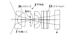
(実施例2)
この実施例は、図5に示すように、偏心補正手段としてくさびフィルター23を用いる実施例である。すなわち、先端レンズ3以降のレンズ系の中にくさびフィルター23を設ける。くさびフィルター23というのは、フィルター面すなわち平行平面を相互に角度をなすように光軸に対して傾けたものである。
【0035】
図6に示すように、レンズ21のレンズ面22(図(a))やレンズ21(図(b))自身を中心軸に対して傾けることをティルトと称することにする。なお、偏心とは、上記のシフト及びこのティルトを含めたものを表す。
【0036】
平行平板をくさびフィルターとすることで、プリズム作用によってこれを通過する光線を曲げたり、逆に曲げないようにしたりすることができる。したがって、これによりくさびレンズ3第1面の平面部への光線入射角を変えて、偏角及び画角ばらつきを抑えることができる。
【0037】
この場合の偏角は約2°、くさびレンズ3の頂角方向の画角及びその反対方向の画角共約65°とすることができ、画角約130°の広角な直視対物系2が構成できる。
なお、このくさびフィルター23のくさび角は、光学系の先端くさびレンズ3の配置と逆向きになるようにするのがよい。つまり、プリズムの頂角が互いに逆向きになるように配置すればよい。
【0038】
この例では像面に近い箇所の平行平板をくさびフィルター23としたが、この位置以外に配置してもよいし、CCD4のカバーガラスをこのようなくさびフィルター23で構成してもよい。
【0039】
(実施例3)
この実施例は、図7に示すように、偏心補正手段としてレンズをくさびレンズ24にする実施例である。実施例2では、平行平板をくさびフィルター23としたが、この実施例は、さらに絞り8前に配置したレンズ24をくさび状に構成した実施例である。なお、くさびフィルター23を用いずに、くさびレンズ24だけで構成することも可能である。このときも、実施例2のように、プリズムの頂角が互いに逆向きになるように配置するとよい。さらに、偏心させるレンズも1個に限るわけでもなく、2個以上を偏心させてもよいし、個々のレンズの偏心の仕方も色々組み合わせてもよい。
【0040】
この実施例において、くさびレンズ24を絞り8前に配置することで、先端レンズ3によって発生する偏角等を絞り8前群のレンズ系で補正しようとしたものである。なお、偏心させるレンズは、先端レンズ3以降のどれでもよいし、レンズ面は1面でも2面以上でも光軸に対して傾けてよい。さらに、このレンズの偏心の仕方は、光軸に対して傾けるだけでなく、併せて光軸に対して垂直に動かしてもよい。偏心させるレンズを複数設けることで、各レンズの頂角が小さくなって収差補正がしやすくなる。この実施例では、実施例2に対して、くさびフィルター23のくさび角が約7.5°から約5.8°と小さくなっている。
【0041】
また、この場合の偏角は約2.6°、くさびレンズ3の頂角方向の画角及びその反対方向の画角共約65°とすることができ、画角約130°の広角な直視対物系が構成できる。
【0042】
(実施例4)
この実施例は、図8に示すように、偏心補正手段としてレンズ系の一部25を偏心させる実施例である。図8の場合、絞り8前の第2レンズ25を光軸に対して垂直にずらしたものである。これも、絞り8前に配置することで、第1レンズ(先端レンズ)3によって発生する偏角等を絞り8前群のレンズ系で補正しようとしたものである。
【0043】
すなわち、先端レンズ3以降のレンズ系中のレンズを光軸に対して垂直にずらしたものであり、これはレンズを特にくさび状とはしていないが、レンズを偏心させることで、上記の実施例と同様な効果を持たせることができる。つまり、この偏心させたレンズによって光線の屈折角が変わることで、くさびレンズ3第1面の平面部への光線入射角度が変わるため、偏角及び画角ばらつきを抑えることができる。
【0044】
なお、1個のレンズをずらすと、レンズ面が2面共中心軸に対して偏心することになるが、これとは別にどちらか1面だけをずらしたような形状のレンズで構成してもよい。もちろん、レンズ面1面やレンズ1個には限らない。
【0045】
図8の場合も、同様に偏角は約1.8°、くさびレンズ3の頂角方向の画角及びその反対方向の画角共約65°とすることができ、画角約130°の広角な直視対物系が構成できる。
【0046】
(実施例5)
この実施例は、図9に示すように、偏心補正手段として、対物系2を構成する対物レンズ系26とCCD4とを光軸に対して互いに垂直にずらした実施例である。CCD(撮像面)4を光軸に対して垂直に移動させることで、対物系2先端がくさびレンズ3になっていることで発生する偏角を補正している。これは、視野方向及び視野範囲のバランスのとれた位置に撮像面を移動させることに他ならない。
【0047】
なお、この場合の偏角は約2.6°、くさびレンズ3の頂角方向の画角及びその反対方向の画角共約65°とすることができ、画角約130°の広角な直視対物系が構成できる。
【0048】
(実施例6)
この実施例は、図10に示すように、偏心補正手段として、絞り8前後のレンズ群27、28を互いに偏心させた実施例であり、ここでは、絞り8の後群28と共にCCD4も一緒に偏心させている。これは、絞り8の前群27をまとめて偏心させたことと同じであり、対物系2先端がくさびレンズ3になっていることで発生する偏角を絞り8の前群27を偏心させることで補正している。
【0049】
なお、この場合の偏角は約1.4°、くさびレンズ3の頂角方向の画角及びその反対方向の画角共約67°とすることができ、画角約135°の広角な直視対物系が構成できる。
【0050】
(実施例7)
この実施例は、図11に示すように、偏心補正手段として、先端レンズ3をくさびレンズにして、対物系2全体を傾ける実施例である。
光学系先端の傾け角が小さければそのまま通常の直視系を傾けてもよいが、傾け角が大きい場合は斜視系となるので、偏心補正が必要である。そこで、先端レンズ3をくさびレンズとしながら、さらにCCD(撮像面)4を含む対物系2全体を傾けることで、くさびレンズ3による偏角を補正しながら、光学系の視野方向とスコープの長手方向とを概略一致させることができる。
【0051】
この実施例の特徴として、先端レンズ3にスコープ先端部の傾斜角よりも小さなくさび角を与え、後はスコープ傾斜角に合わせて光学系全体を傾ければよいことである。このため、元々偏角や画角ばらつきは小さくて済むし、また、偏角の発生方向とば逆方向に光学系全体を傾けることで、偏角の補正ができる。
【0052】
なお、この場合の偏角は約2.4°、くさびレンズ3の頂角方向の画角及びその反対方向の画角共約67°とすることができ、画角約135°の広角な直視対物系が構成できる。
【0053】
(実施例8)
この実施例は、図12に示すように、偏心補正手段として、先端レンズ3を通常の凹レンズで構成し、その凹レンズ傾ける実施例である。図12に示すように、平凹レンズ3を傾けて配置することにより、光学系の第1面は斜めに構成される。しかし、そのままではレンズ3の凹面側も斜めになるため、偏角が発生してしまう。そこで、このレンズ3をさらに光軸に対して垂直方向に移動させることで、レンズ第1面への光線入射角度を変えることができる。これにより、偏角及び画角ばらつきを抑えることができる。なお、このレンズ3を光軸に対して動かすというのは、この凹面側を光軸に対して動かして補正するということに他ならない。
【0054】
なお、この場合の偏角は約1.6°、先端レンズ3の頂角方向の画角及びその反対方向の画角共約67°とすることができ、画角約135°の広角な直視対物系が構成できる。
【0055】
(実施例9)
この実施例は、図13に示すように、偏心補正手段として、CCD4やイメージガイドファイバー等の結像面を傾ける実施例である。結像面を傾けることにより、場所により像面位置が光学系に近くなったり遠くなったりする。像面位置が近くなると、画角は大きめとなり、像面位置が遠くなると、画角は小さめになることを利用したものである。
【0056】
すなわち、先端のくさびレンズ3によって偏角が発生する方向の画角は大きくなり、反対側では画角が小さくなるため、画角の小さい方に対しては像面位置を近づけることで画角が大きくなるように補正し、逆に、画角の大きい方に対しては像面位置を遠ざけることで画角が小さくなるように補正する。このようにして、偏角及び画角ばらつきを抑えることができる。したがって、先端くさびレンズ3とこの結像面の傾きとの関係は、略平行な形となるように構成することが望ましい。
【0057】
なお、この場合の偏角は約0.5°、くさびレンズ3の頂角方向の画角及びその反対方向の画角共約66°とすることができ、画角約130°の広角な直視対物系が構成できる。
【0058】
(実施例10)
この実施例は、図14に示すように、偏心補正手段として、くさびレンズとして構成した先端レンズ3の像面側をパワーの異なる非球面29とした実施例である。
以上の実施例では、主にレンズ系を偏心させることで光線の屈折角度を変えて、偏角や画角のばらつきを補正していた。ここでは、レンズ系を偏心させないが、レンズ面を非球面とすることで、光線の屈折角度を任意に変えるようにして偏角や画角のばらつきを補正したものであり、図14の場合、くさびレンズ3の像面側レンズ面を非球面29としたものである。この非球面29は、図14に示したように、くさびレンズ3の頂角方向に射出する光線に対しては射出角度がより大きくなるように、くさびレンズ3の像面側の面の曲率半径がより小さく、光線屈折力がより大きくなるような非球面形状であり、一方、くさびレンズ3の底辺方向に射出する光線に対しては射出角度がより小さくなるように、くさびレンズ3の像面側の面の曲率半径がより大きく、光線屈折力がより小さくなるような非球面形状とする。このようにして、偏角及び画角ばらつきを小さく抑えることができる。
【0059】
この場合の偏角は約1.4°、くさびレンズ3の頂角方向の画角及びその反対方向の画角共約67°とすることができ、画角約135°の広角な直視対物系が構成できる。
【0060】
なお、例えば図27(b)に示すように、図27(a)の紙面に垂直な方向では先端レンズ3がくさびレンズではない場合、上記のような非対称形な非球面形状にする必要はない。
【0061】
また、以上の各実施例において、先端レンズ3は、図27(a)及び(b)のように、各断面方向におけるレンズの屈折作用が異なるので、いわゆるアナモルフィックレンズで構成するとよい。また、収差補正のために、各実施例の中でさらにアナモルフィックレンズを用いてもよい。
【0062】
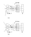
なお、以上の説明では、図24の断面A方向のみでくさび形状の作用を持つものについて考えてきたが、スコープ先端部1の形状が略円錐形ではなく、図25に示すように、いびつな形状をしているような場合では、図25中の断面A内以外にもレンズが傾くことになる。この場合には、対物系光軸11を含み、この断面Aに垂直な断面B内においても対物系2がくさび作用を持つことになるため、これに対しても上記と同様な構成にして、偏心補正作用を持つような構成すればよい。もちろん、実際は、これらの合成状態にて補正することになるが、例えば前記のような断面A、Bを基準に考えた2方向成分に分けて考えると分かりやすい。つまり、図26(a)と(b)に示すように、先端レンズ3の断面A内のレンズ構成及び断面B内のレンズ構成が何れもくさびレンズ構成になるということである。
【0063】
また、レンズ面は平面に限らず非球面等の曲面としてもよい。さらに、レンズ形状も、必ずしも回転対称形である必要はなく、非対称形や方向により光線の屈折作用の異なるいわゆるアナモルフィックレンズであってもよい。
【0064】
以下に、通常のレンズ以外の別の光学素子を用いた例について説明する。
(実施例11)
今までは、通常の均質媒質(均質ガラス)レンズを考えていたが、不均質媒質を用いたレンズ系を用いることもできる。つまり、不均質媒質レンズ自身を偏心させてもよい。
【0065】
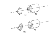
図15はその実施例を示す断面図であり、先端レンズ3の直後に配置されたレンズ30が不均質媒質レンズであり、ここでは凸レンズ作用を持たせた不均質媒質レンズを偏心させている。この不均質媒質レンズ30はラジアル型屈折率分布レンズといわれるもので、図16(a)に屈折率n分布を示すように、軸(中心軸)を中心に回転対称な屈折率分布を有している。また、分布の中心を偏心させて心取りを行えば、図16(b)に示すように、軸対称形でない屈折率分布になるが、これを用いてもよい。
【0066】
なお、不均質媒質レンズ30はラジアル型に限るわけではなく、他の屈折率分布を持った不均質媒質レンズを用いることもできる。また、先端レンズ3の次に不均質媒質レンズを配置したが、別の位置に配置してももちろんよい。
【0067】
この場合も偏角が約3°以下で、くさびレンズ3の頂角方向の画角及びその反対方向の画角共約65°とすることができ、画角約130°の広角な直視対物系が構成できる。
【0068】
(実施例12)
この実施例は、図17に示すように、先端レンズ3を構成するくさびレンズの像面側の面を回折作用を持った回折格子31で構成した実施例である。図17には対物系先端部だけを図示してある。
くさびレンズ3の頂角方向の光線はこの回折格子31面で大きく屈折されて光線が射出されるため、画角が大きくなる。一方、反対側の光線は逆にこの回折格子31面で小さく屈折されて光線が射出されるため、画角が小さくなる。図18(a)にこの回折格子31の構成概念図を示す。ここでは、光線の屈折作用が大きい方は格子間隔が密になるようにし、光線の屈折作用が小さい方は格子間隔が粗になるようにしてある。なお、格子パターンは、図18(a)のような一次元方向でもよいし、図18(b)のように同心円状パターンを偏心させてもよいし、非回転対称形の特性を持たせてもよい。また、回折格子31の配置位置は、図17の例に限るわけではなく、別の箇所に設けてもよい。
【0069】
この場合も偏角が約3°以下で、くさびレンズ3の頂角方向の画角及びその反対方向の画角共65°とすることができ、画角約130°の広角な直視対物系が構成できる。
【0070】
なお、先端レンズ3の第1面は汚れたり傷つきやすいし、また、スコープを消毒液等で洗浄したりするため、回折格子31面はレンズ表面に出ないようにするのが望ましい。
【0071】
以上述べた光学素子以外のものを用いた実施例と先に述べた実施例の構成とを複数組み合わせて構成してもよい。また、各実施例のように画角が約130°や135°に限るわけではなく、140°やそれ以上でもよいし、逆に120°やそれ以下でも構わない。さらに、対物系の第1面の傾斜角も実施例の値に限定されるわけではない。なお、各実施例で示したようなレンズ構成に限るわけではなく、どのようなレンズ枚数やレンズタイプであっても、本発明を適用することは可能である。
【0072】
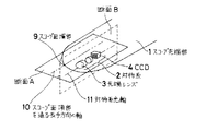
具体的に、図19に実施例2の対物系2を組み込んだ場合のスコープ先端レイアウトを含むスコープ先端部の構成例を示す。図(a)が先端レイアウトを示す図であり、図(b)が図(a)の折れ線AOBに沿う断面図である。また、AO断面はこの対物系2の中心を通っており、AO断面は前述した図24の断面Aに相当している。
【0073】
スコープ面頂9(O)は平面部で、この位置9はこの例ではスコープ中心と等しくなっており、ここを基準に周辺部に向かって滑らかな流線型になるように構成されている。対物系2はスコープ中心からずれた位置に配置されている。また、鉗子チャンネル5や照明系32も同様に配置されている。なお、ノズル33はこの面頂9よりも出っ張ることがあるが、この場合にはスコープ面頂部とは考えない。
もちろん、本発明はこの例に限らず、他の実施例の構成例を適用することもできる。
【0074】
以上、本発明の内視鏡用対物光学系をいくつかの実施例に基づいて説明してきたが、本発明はこれら実施例に限定されず種々の変形が可能である。
【0075】
以上の本発明の内視鏡用対物光学系は例えば次のように構成することができる。
〔1〕 内視鏡先端部に設けられた対物光学系の先端面形状の法線と、内視鏡挿入部の長手方向とが一致しない構成の内視鏡用対物光学系において、前記対物光学系の先端面以降に偏心補正手段を設けることにより、前記対物光学系の視野方向が前記内視鏡挿入部の長手方向と略一致するように構成されていることを特徴とする内視鏡用対物光学系。
【0076】
〔2〕 前記偏心補正手段として、前記対物光学系のレンズ光軸に対して非対称な屈折作用を有する光学素子を設けたことを特徴とする上記〔1〕記載の内視鏡用対物光学系。
【0077】
〔3〕 前記対物光学系の先端レンズが略くさび形状であることを特徴とする上記〔1〕記載の内視鏡用対物光学系。
【0078】
〔4〕 前記対物光学系の第1面が平面であることを特徴とする〔1〕又は〔3〕記載の内視鏡用対物光学系。
【0079】
〔5〕 前記対物光学系の第1面が曲面であることを特徴とする〔1〕又は〔3〕記載の内視鏡用対物光学系。
【0080】
〔6〕 内視鏡先端部の面頂部から外れた位置に対物光学系が配置されていることを特徴とする上記〔1〕記載の内視鏡用対物光学系。
【0081】
〔7〕 前記偏心補正手段が、少なくとも1面以上のレンズ面の偏心であることを特徴とする上記〔1〕記載の内視鏡用対物光学系。
【0082】
〔8〕 前記偏心補正手段が、結像面の偏心であることを特徴とする上記〔1〕記載の内視鏡用対物光学系。
【0083】
〔9〕 前記偏心補正手段として、少なくとも1面以上のレンズ面の偏心及び結像面の偏心の組み合わせであることを特徴とする上記〔1〕記載の内視鏡用対物光学系。
【0084】
〔10〕 前記結像面は、光電変換素子もしくはイメージガイドファイバーの撮像素子の受光面であることを特徴とする上記〔8〕又は〔9〕記載の内視鏡用対物光学系。
【0085】
〔11〕 内視鏡先端部の面頂を通る内視鏡挿入部の長手方向の軸と対物光学系の光軸とを含む面内で前記偏心を行うことを特徴とする上記〔7〕から〔10〕の何れか1項記載の内視鏡用対物光学系。
【0086】
〔12〕 内視鏡先端部の面頂を通る内視鏡挿入部の長手方向の軸と対物光学系の光軸とを含む面内及び対物光学系の光軸を含み、前記面に垂直な面内の2方向を考えたとき、前記2方向の成分で前記偏心を行うことを特徴とする上記〔7〕から〔10〕の何れか1項記載の内視鏡用対物光学系。
【0087】
〔13〕 前記対物光学系がアナモルフィックレンズを含んでいることを特徴とする上記〔1〕又は〔2〕記載の内視鏡用対物光学系。
【0088】
〔14〕 前記対物光学系が非球面レンズを含んでいることを特徴とする上記〔1〕又は〔2〕記載の内視鏡用対物光学系。
【0089】
〔15〕 前記対物光学系が不均質媒質レンズを含んでいることを特徴とする上記〔1〕又は〔2〕記載の内視鏡用対物光学系。
【0090】
〔16〕 前記対物光学系が回折格子を含んでいることを特徴とする上記〔1〕又は〔2〕記載の内視鏡用対物光学系。
【0091】
【発明の効果】
以上の説明から明らかなように、本発明によると、スコープ先端部を流線型形状とした場合に、この形状に光学系の端面形状を合わせながら、光学系の偏角及び画角ばらつきを抑えた直視対物光学系を提供することができる。これにより、特にスコープ細径化に対しても、画質性能を劣化させることなく、スコープ先端部の流線型化が実現できる。
【図面の簡単な説明】
【図1】スコープ先端部の概略構成を示す図である。
【図2】スコープ先端部を流線型化した場合の概略構成を示す図である。
【図3】本発明の実施例1の内視鏡用対物光学系の断面図である。
【図4】レンズ面及びレンズのシフトを説明するための図である。
【図5】本発明の実施例2の内視鏡用対物光学系の断面図である。
【図6】レンズ面及びレンズのティルトを説明するための図である。
【図7】本発明の実施例3の内視鏡用対物光学系の断面図である。
【図8】本発明の実施例4の内視鏡用対物光学系の断面図である。
【図9】本発明の実施例5の内視鏡用対物光学系の断面図である。
【図10】本発明の実施例6の内視鏡用対物光学系の断面図である。
【図11】本発明の実施例7の内視鏡用対物光学系の断面図である。
【図12】本発明の実施例8の内視鏡用対物光学系の断面図である。
【図13】本発明の実施例9の内視鏡用対物光学系の断面図である。
【図14】本発明の実施例10の内視鏡用対物光学系の断面図である。
【図15】本発明の実施例11の内視鏡用対物光学系の断面図である。
【図16】回転対称及び偏心した屈折率分布を有するラジアル型屈折率分布レンズを説明するための図である。
【図17】本発明の実施例12の内視鏡用対物光学系の先端部の断面図である。
【図18】実施例12において用いる回折格子の構成概念図である。
【図19】1つの具体例のスコープ先端レイアウト及びその断面を示す図である。
【図20】通常の対物系の先端レンズに用いられる平凹レンズの断面図である。
【図21】平凹レンズの第1面を傾斜させた場合の光線の屈折の仕方を説明するための図である。
【図22】別の光線に対する図21と同様な図である。
【図23】図21において像面側凹面を偏心させて場合の光線の屈折の仕方を説明するための図である。
【図24】スコープ先端部を流線型化しその面頂部から外れた位置に対物系を配置した場合の構成図である。
【図25】スコープ先端部をいびつな形状にした場合の図24と同様な図である。
【図26】図25の構成の場合の直交する2つの断面内の1実施例のレンズ構成を示す図である。
【図27】スコープ先端レンズをくさびレンズとした場合の内視鏡用対物光学系の直交する2つの断面図である。
【符号の説明】
1…スコープ先端部
2…対物系
3…先端レンズ
3’…凹面
4…CCD
5…鉗子チャンネル
6…観察範囲
7…スコープ先端面取り部
8…絞り
9…スコープ面頂部
10…スコープ長手方向の軸
11…対物系中心部(光軸)
20…平凹レンズ
21…レンズ
22…レンズ面
23…くさびフィルター
24…くさびレンズ
25…レンズ系の一部
26…対物レンズ系
27…前群レンズ群
28…後群レンズ群
29…非球面
30…不均質媒質レンズ
31…回折格子
32…照明系
33…ノズル[0001]
BACKGROUND OF THE INVENTION
The present invention relates to an endoscope objective optical system widely used in medical and industrial fields.
[0002]
[Prior art]
An endoscope (hereinafter referred to as a scope) is inserted into a thin lumen or the like and used for internal observation.
In particular, in medical scopes, the scope is inserted into many lumens in the body for diagnosis and treatment. When the scope is inserted, the scope tip first contacts the wall of the lumen, etc. If the peripheral part is sharp, the insertability is deteriorated by being caught on the wall surface. In addition, the longer the examination time is due to poor insertion, the greater the burden on the patient.
[0003]
Therefore, in the case of the conventional direct-view scope, as shown in the schematic configuration of the scope distal end portion in FIG. 1, the
[0004]
However, by making the entire scope tip more round and streamlined, the scope can be inserted more smoothly without being caught by the observation object even if the tip contacts the observation object, etc. In addition, the improvement of the operability and handling of the operator can be expected to shorten the examination time and reduce the patient's pain.
[0005]
However, if the entire scope tip is made into a more streamlined shape, the shape of the end face of the optical system, forceps channel, etc. is also affected by the scope tip shape. That is, as shown in FIG. 2, it is necessary to match the end face shapes of the
[0006]
By the way, in a direct-view scope with a relatively large scope diameter, the space around the scope can be reduced by arranging the arrangement space for the objective system, forceps channel, air supply / water supply nozzle, etc. near the scope center. Can also be rounded and streamlined.
[0007]
However, at present, the scope itself has become smaller in diameter in order to further improve scope insertion and reduce patient pain, so it takes up most of the space at the tip of the scope just by placing an optical system, etc. It becomes a situation. Therefore, if the entire scope tip is made into a more streamlined shape, the end face shape of the objective system, forceps channel, etc. must be the same as the scope tip shape, resulting in a perspective optical system as described in FIG. . The shape of the end face of the objective system may not be exactly the same as the shape of the scope tip, but it is necessary to roughly match the scope shape of the portion where the objective system is arranged.
[0008]
Conventionally, for example, in Japanese Utility Model Laid-Open No. 54-87688 and Japanese Utility Model Laid-Open No. 4-50002, the portion except the objective system at the front end portion of the direct-view scope is configured as a curved surface, but this reduces the diameter of the scope. In such a case, since the flat portion remains at the distal end, the entire scope distal end cannot be rounded.
[0009]
Further, examples in which the tip shape of the objective system is rounded include those disclosed in Japanese Utility Model Laid-Open No. 64-36816 and Japanese Patent Laid-Open No. 4-102432. In these, the scope tip has a convex shape, and an objective system is formed on the top of the surface. Here, since the tip portion has a convex shape, the insertion into the body cavity is improved and the pain of the patient is reduced. In addition, the front-end | tip part of the used objective system is R shape, and is a normal direct view system. However, when the diameter of the scope tip is reduced, the objective system may not necessarily be formed on the top of the surface due to the layout. For this reason, an ordinary rotationally symmetric optical system may be configured to match the tip shape. Can not. Even if the optical system is configured in accordance with the tip shape, for example, it becomes a non-rotationally symmetric lens such as a wedge lens, so that the optical system is not a direct view system but a perspective system. Here, the non-rotationally symmetric shape does not indicate the external shape of the lens, but indicates that the refraction action of the light beam by this lens is not the rotation-symmetric action as in a normal lens.
[0010]
Further, in Japanese Patent Publication No. 5-37649, the distal end portion of the scope insertion portion has a substantially continuous hemispherical shape, and is configured as a convex lens that coincides with the optical axis of the objective system. As a result, smooth insertion into the body cavity and reduction of patient's pain are aimed at, and this is also constituted by a normal rotationally symmetric direct-view system having a R-shaped tip at the top of the tip. However, if it is not possible to construct a rotationally symmetric lens even if an optical system is arranged on the top of the surface, or if it cannot be constructed on the top of the surface due to a reduction in the diameter of the tip, etc., the optical system of the perspective system as in the previous example End up.
[0011]
In this way, when the scope tip is streamlined and the objective system is arranged at a position off the top of the tip surface, it is necessary to make it close to this inclined surface shape, but the simplest configuration is the objective tip It has a substantially wedge shape with a flat surface. Of course, the end face of the optical system is not limited to a flat surface, but may be a curved surface or a combination of a flat surface and a curved surface. However, in order to simplify the description, the following description will be based on the wedge shape of a flat surface. .
[0012]
In such a perspective system, the angle of view also increases or decreases depending on the viewing direction, and as a result, a wide range cannot be observed. In particular, since the angle of view of the objective system is as large as 120 °, 140 °, etc. so as to observe a wide range, variation in the angle of view due to the influence of the amount of declination becomes very large.
[0013]
Here, the variation in the angle of view is, for example, as shown in FIG. 27A, the angle of the light beam emitted from the wedge lens constituting the
[0014]
The amount of declination varies depending on the end surface tilt angle of the objective system due to the streamlined shape at the tip of the scope. Or the distribution of light will be reduced because the illumination light is not sufficiently transmitted. Of course, if the tilt angle of the end face of the objective system is small or the angle of view of the original objective optical system is small, there is no need to worry about decentration and variations in the angle of view. There is no problem at all. Although the influence on the angle of view differs depending on the angle of view and the direction of the declination, as a guideline for the angle of view of about 140 °, if the declination is about 5 ° or less, there is not much problem in scope performance. However, if it exceeds this, it is not good because the vignetting and light distribution are insufficient. Naturally, even if the design value is not more than the above, the actual product may be decentered due to tolerance variations and the like. For this reason, it is necessary to suppress the declination as much as possible at the time of design. When the angle of view is originally large, it is necessary to pay attention not only to the deflection angle but also to the variation in the angle of view, and it is also necessary to suppress the variation in the angle of view. FIG. 27B shows a lens cross-sectional view in a direction perpendicular to the paper surface of FIG. 27A. In this direction, since the
[0015]
[Problems to be solved by the invention]
As described above, particularly when the entire front end portion of the direct-viewing system scope is configured to be a streamlined shape, the objective system needs to be matched to this shape.
However, simply matching the scope tip shape causes the objective system end surface to be non-rotationally symmetric with respect to the central axis, resulting in a declination and a perspective system. For this reason, it becomes impossible to obtain a sufficient observation range such that the variation in the angle of view increases with the magnitude of the generated declination and the field vignetting occurs.
Here, the central axis is an axis that passes through the center of the aperture perpendicular to the aperture stop, and in the following, this central axis is considered as a reference. This central axis coincides with the normal optical axis if the lens system is a non-decentered lens system, but does not coincide with the optical axis of the decentered lens if it is an eccentric lens system.
[0016]
Therefore, an object of the present invention is to suppress the deflection angle and field angle variation generated by configuring the objective optical system end face in a non-rotationally symmetric shape with respect to the central axis in accordance with the streamline type of the endoscope distal end, The aim is to provide an advanced streamlined endoscope with the same specifications and performance as a direct vision system.
[0017]
[Means for Solving the Problems]
In order to achieve the above object, an endoscope objective optical system according to the present invention has a normal of the distal end surface shape of the objective optical system provided at the endoscope distal end and the longitudinal direction of the endoscope insertion portion. In an endoscope objective optical system having a configuration that does not match, by providing a decentration correction means after the distal end surface of the objective optical system, the visual field direction of the objective optical system substantially coincides with the longitudinal direction of the endoscope insertion portion It is comprised so that it may carry out.
[0018]
That is, in the endoscope objective optical system according to the present invention, when the tip shape of the objective optical system is matched with the streamlined shape of the endoscope tip, the lens surface is decentered and the lens shape becomes asymmetric. Deviations, field angle variations, etc. occur. This is to be corrected by an eccentricity correction means provided after the front end surface of the objective optical system.
[0019]
Hereinafter, the reason and action of the above configuration in the present invention will be described in detail.
As described above, if the scope (endoscope) tip is streamlined, it is inevitable to match the shape of the tip of the objective system to that, and the lens is simply a wedge-shaped lens. If such a lens that is not rotationally symmetric is used, deviations in angle and field angle occur.
[0020]
Now, let us consider a case where the
[0021]
On the other hand, in the cross section B that is perpendicular to the cross section A and includes the
[0022]
A plano-
n · sin (θ + φ) = n i ・ Sin (θ i + Φ) (1)
Here, n is a refractive index in the air, and n = 1.
[0023]
Since it is θ + φ = 90 ° that the light beam passes through the first surface of the
φ = sin -1 (1 / n i ) −θ i ... (2)
In the case of a light ray as shown in FIG. 22A, the equation (1) may be replaced with the following equation and considered similarly.
n · sin (θ−φ) = n i ・ Sin (θ i −φ) (1 ′)
It becomes.
[0024]
Table 1 below summarizes the numerical values from these relationships.
That is, the inclination angle φ of the first surface cannot be increased so much that the light rays are totally reflected immediately, and vignetting occurs in the objective system. The fact that the tilt angle is small means that the scope tip cannot be made too round, and even if the tilt angle is increased forcibly, field vignetting only occurs.
[0026]
In addition, as can be seen from Table 1, the angle of view quickly increases with a slight tilt angle, so a wide-angle scope with an angle of view of 120 °, etc., will not reach the illumination light, resulting in insufficient light distribution. End up.
In order to avoid this, it is necessary to reduce the incident angle of light on the first surface. In the case of a light beam as shown in FIG. 22 (a), it is necessary to enlarge it.
[0027]
Here, when the ray is traced back, the ray incident angle θ of the first surface is i Just change. For this purpose, by changing the lens configuration after this surface, the light refraction angle is changed to change the light incident angle θ on the first surface. i Must be changed.
Specifically, as shown in FIG. 21 (b), the light incident angle here is reduced (θ i > Θ i ' As shown in FIG. 22B, the incident angle of the light beam is increased (θ). i <Θ i ' This is how the light beam is bent and incident.
[0028]
Therefore, considering the same ray as in FIG. 21 (a) by backtracking, if the image surface side concave surface of the
[0029]
Thus, when the
[0030]
As described above, in the endoscope objective optical system according to the present invention, the deviation of the objective system and the variation in the angle of view are suppressed by matching the end face shape of the objective optical system with the streamlined shape of the scope tip. The same so-called direct view system can be configured.
[0031]
DETAILED DESCRIPTION OF THE INVENTION
Hereinafter, some embodiments of the endoscope objective optical system of the present invention will be described in detail. Each embodiment shows a lens configuration based on the central axis.
Example 1
In this embodiment, as shown in FIG. 3, the wedge lens constituting the
[0032]
As shown in FIG. 4, moving the lens surface 22 (FIG. (A)) of the
[0033]
In this case, the declination angle is about 1.7 °, and the field angle in the apex direction of the
In this case, the inclination angle of the first surface of the objective system is about 5 °, and the same applies to the following embodiments.
[0034]
(Example 2)
In this embodiment, as shown in FIG. 5, a wedge filter 23 is used as the eccentricity correcting means. That is, the wedge filter 23 is provided in the lens system after the
[0035]
As shown in FIG. 6, tilting the lens surface 22 (FIG. (A)) or the lens 21 (FIG. (B)) itself of the
[0036]
By using a parallel plate as a wedge filter, it is possible to bend the light beam passing through the prism by the prism action, or to avoid bending it. Therefore, this makes it possible to change the angle of incidence of light on the flat portion of the first surface of the
[0037]
In this case, the declination angle can be about 2 °, and the angle of view of the
It is preferable that the wedge angle of the wedge filter 23 is opposite to the arrangement of the
[0038]
In this example, the parallel plate near the image plane is used as the wedge filter 23. However, it may be arranged at a position other than this position, or the cover glass of the
[0039]
Example 3
In this embodiment, as shown in FIG. 7, a wedge lens 24 is used as a decentering correction means. In the second embodiment, the parallel plate is the wedge filter 23. However, this embodiment is an embodiment in which the lens 24 arranged in front of the
[0040]
In this embodiment, the wedge lens 24 is disposed in front of the
[0041]
In this case, the declination angle is about 2.6 °, and the angle of view of the
[0042]
Example 4
In this embodiment, as shown in FIG. 8, a part 25 of the lens system is decentered as a decentering correction means. In the case of FIG. 8, the second lens 25 in front of the
[0043]
That is, the lens in the lens system after the
[0044]
If one lens is shifted, the lens surface will be decentered with respect to the biaxial central axis. Alternatively, it may be configured by a lens having a shape in which only one surface is shifted. Good. Of course, it is not limited to one lens surface or one lens.
[0045]
In the case of FIG. 8 as well, the declination angle can be about 1.8 °, and the angle of view of the
[0046]
(Example 5)
As shown in FIG. 9, this embodiment is an embodiment in which the objective lens system 26 and the
[0047]
In this case, the declination angle is about 2.6 °, and the angle of view in the apex direction of the
[0048]
(Example 6)
In this embodiment, as shown in FIG. 10, the lens groups 27 and 28 before and after the
[0049]
In this case, the declination angle can be about 1.4 °, and the angle of view of the
[0050]
(Example 7)
As shown in FIG. 11, this embodiment is an embodiment in which the entire
If the tilt angle of the tip of the optical system is small, the normal direct-view system may be tilted as it is. However, if the tilt angle is large, a perspective system is used, and decentration correction is necessary. Therefore, by tilting the entire
[0051]
As a feature of this embodiment, a wedge angle smaller than the inclination angle of the distal end portion of the scope is given to the
[0052]
In this case, the declination angle can be about 2.4 °, and the angle of view of the
[0053]
(Example 8)
In this embodiment, as shown in FIG. 12, the
[0054]
In this case, the declination angle is about 1.6 °, and the angle of view of the
[0055]
Example 9
In this embodiment, as shown in FIG. 13, an image forming surface such as a
[0056]
That is, the field angle in the direction in which the declination is generated is increased by the
[0057]
In this case, the declination angle can be about 0.5 °, and the angle of view of the
[0058]
(Example 10)
In this embodiment, as shown in FIG. 14, an aspherical surface 29 having different power is used on the image surface side of the
In the above embodiments, the deflection angle and the angle of view are corrected by changing the refraction angle of the light beam mainly by decentering the lens system. Here, the lens system is not decentered, but the lens surface is aspherical so that the refraction angle of the light beam is arbitrarily changed to correct the deviation of the deflection angle and the angle of view. The image side lens surface of the
[0059]
In this case, the declination angle can be about 1.4 °, and the angle of view of the
[0060]
For example, as shown in FIG. 27 (b), when the
[0061]
In each of the above embodiments, the
[0062]
In the above description, a case having a wedge-shaped action only in the direction of the cross section A in FIG. 24 has been considered. However, the shape of the
[0063]
The lens surface is not limited to a flat surface, and may be a curved surface such as an aspherical surface. Further, the lens shape does not necessarily need to be rotationally symmetric, and may be a so-called anamorphic lens in which the light refraction action differs depending on the asymmetric shape or direction.
[0064]
Hereinafter, an example in which another optical element other than a normal lens is used will be described.
(Example 11)
Up to now, an ordinary homogeneous medium (homogeneous glass) lens has been considered, but a lens system using an inhomogeneous medium can also be used. That is, the heterogeneous medium lens itself may be decentered.
[0065]
FIG. 15 is a cross-sectional view showing an embodiment thereof. A
[0066]
The inhomogeneous
[0067]
In this case as well, a wide-angle direct-view objective system having a declination angle of about 3 ° or less and an angle of view in the apex direction of the
[0068]
(Example 12)
In this embodiment, as shown in FIG. 17, the surface on the image plane side of the wedge lens constituting the
The light beam in the apex direction of the
[0069]
Also in this case, the declination angle is about 3 ° or less, the angle of view of the
[0070]
Note that the first surface of the
[0071]
You may comprise combining the Example using things other than the optical element described above, and the structure of the Example described previously in multiple numbers. Further, the angle of view is not limited to about 130 ° or 135 ° as in each embodiment, but may be 140 ° or more, or conversely, 120 ° or less. Furthermore, the inclination angle of the first surface of the objective system is not limited to the values in the embodiments. The present invention is not limited to the lens configuration as shown in each embodiment, and the present invention can be applied to any number of lenses and lens types.
[0072]
Specifically, FIG. 19 shows a configuration example of a scope tip including a scope tip layout when the
[0073]
The scope top 9 (O) is a plane portion, and this
Of course, the present invention is not limited to this example, and configuration examples of other embodiments can be applied.
[0074]
As mentioned above, although the objective optical system for endoscopes of the present invention has been described based on several embodiments, the present invention is not limited to these embodiments, and various modifications are possible.
[0075]
The above-described endoscope objective optical system of the present invention can be configured as follows, for example.
[1] In the endoscope objective optical system having a configuration in which the normal of the distal end surface shape of the objective optical system provided at the endoscope distal end and the longitudinal direction of the endoscope insertion portion do not coincide with each other, the objective optical An endoscope for an endoscope characterized in that a decentration correction means is provided after the distal end surface of the system so that the visual field direction of the objective optical system substantially coincides with the longitudinal direction of the endoscope insertion portion. Objective optical system.
[0076]
[2] The endoscope objective optical system according to [1], wherein an optical element having an asymmetric refractive action with respect to a lens optical axis of the objective optical system is provided as the decentration correction means.
[0077]
[3] The endoscope objective optical system according to [1], wherein a tip lens of the objective optical system has a substantially wedge shape.
[0078]
[4] The endoscope objective optical system according to [1] or [3], wherein the first surface of the objective optical system is a flat surface.
[0079]
[5] The endoscope objective optical system according to [1] or [3], wherein the first surface of the objective optical system is a curved surface.
[0080]
[6] The endoscope objective optical system as set forth in [1], wherein the objective optical system is disposed at a position deviated from the top of the endoscope tip.
[0081]
[7] The endoscope objective optical system according to [1], wherein the decentration correcting means is decentering of at least one lens surface.
[0082]
[8] The endoscope objective optical system according to [1], wherein the decentration correction means is decentering of an image plane.
[0083]
[9] The endoscope objective optical system according to [1], wherein the decentering correction means is a combination of decentering of at least one lens surface and decentering of an imaging surface.
[0084]
[10] The endoscope objective optical system according to [8] or [9], wherein the imaging surface is a light receiving surface of an image sensor of a photoelectric conversion element or an image guide fiber.
[0085]
[11] From the above [7], wherein the decentering is performed in a plane including the longitudinal axis of the endoscope insertion portion passing through the top of the distal end portion of the endoscope and the optical axis of the objective optical system. [10] The endoscope objective optical system according to any one of [10].
[0086]
[12] In-plane including the longitudinal axis of the endoscope insertion portion passing through the top of the endoscope distal end and the optical axis of the objective optical system and the optical axis of the objective optical system, and perpendicular to the surface The endoscope objective optical system according to any one of [7] to [10], wherein the decentering is performed with components in the two directions when two directions in the plane are considered.
[0087]
[13] The endoscope objective optical system according to [1] or [2], wherein the objective optical system includes an anamorphic lens.
[0088]
[14] The endoscope objective optical system according to [1] or [2], wherein the objective optical system includes an aspheric lens.
[0089]
[15] The endoscope objective optical system according to [1] or [2], wherein the objective optical system includes a heterogeneous medium lens.
[0090]
[16] The endoscope objective optical system according to [1] or [2], wherein the objective optical system includes a diffraction grating.
[0091]
【The invention's effect】
As is apparent from the above description, according to the present invention, when the scope tip has a streamlined shape, direct viewing with reduced deflection angle and angle of view of the optical system while matching the shape of the end face of the optical system to this shape. An objective optical system can be provided. As a result, the streamlined tip of the scope can be realized without degrading the image quality performance, especially when the scope is narrowed.
[Brief description of the drawings]
FIG. 1 is a diagram showing a schematic configuration of a distal end portion of a scope.
FIG. 2 is a diagram showing a schematic configuration when a scope tip is streamlined.
FIG. 3 is a cross-sectional view of an endoscope objective optical system according to Example 1 of the present invention.
FIG. 4 is a diagram for explaining lens surfaces and lens shifts.
FIG. 5 is a cross-sectional view of an endoscope objective optical system according to Example 2 of the present invention.
FIG. 6 is a diagram for explaining a lens surface and lens tilt.
FIG. 7 is a cross-sectional view of an endoscope objective optical system according to Example 3 of the present invention.
FIG. 8 is a cross-sectional view of an endoscope objective optical system according to Example 4 of the present invention.
FIG. 9 is a cross-sectional view of an endoscope objective optical system according to Example 5 of the present invention.
FIG. 10 is a cross-sectional view of an endoscope objective optical system according to Example 6 of the present invention.
FIG. 11 is a cross-sectional view of an endoscope objective optical system according to Example 7 of the present invention.
FIG. 12 is a sectional view of an endoscope objective optical system according to Example 8 of the present invention.
FIG. 13 is a cross-sectional view of an endoscope objective optical system according to Example 9 of the present invention.
FIG. 14 is a cross-sectional view of an endoscope objective optical system according to Example 10 of the present invention.
15 is a sectional view of an endoscope objective optical system according to Example 11 of the present invention; FIG.
FIG. 16 is a view for explaining a radial type refractive index distribution lens having a refractive index distribution that is rotationally symmetric and decentered.
FIG. 17 is a cross-sectional view of a distal end portion of an endoscope objective optical system according to a twelfth embodiment of the present invention.
18 is a structural conceptual diagram of a diffraction grating used in Example 12. FIG.
FIG. 19 is a diagram showing a scope tip layout and a cross section thereof according to one specific example;
FIG. 20 is a cross-sectional view of a plano-concave lens used for a tip lens of a normal objective system.
FIG. 21 is a diagram for explaining how a light beam is refracted when the first surface of the plano-concave lens is tilted.
FIG. 22 is a view similar to FIG. 21 for another ray.
FIG. 23 is a diagram for explaining how light is refracted when the image-side concave surface is decentered in FIG. 21;
FIG. 24 is a configuration diagram in the case where the scope tip is streamlined and the objective system is disposed at a position off the top of the surface.
FIG. 25 is a view similar to FIG. 24 in the case where the distal end portion of the scope has an irregular shape.
FIG. 26 is a diagram illustrating a lens configuration of an example within two orthogonal cross sections in the case of the configuration of FIG. 25;
FIGS. 27A and 27B are two cross-sectional views orthogonal to the endoscope objective optical system when the scope tip lens is a wedge lens. FIGS.
[Explanation of symbols]
1 ... Scope tip
2 ... Objective system
3 ... Lead lens
3 '... concave
4 ... CCD
5 ... Forceps channel
6 ... Observation range
7 ... Scope tip chamfer
8 ... Aperture
9 ... Scope top
10 ... Scope longitudinal axis
11 ... Objective system center (optical axis)
20 ... Plano-concave lens
21 ... Lens
22 ... Lens surface
23 ... Wedge filter
24 ... Wedge lens
25. Part of the lens system
26 ... Objective lens system
27. Front lens group
28 ... Rear lens group
29 ... Aspherical
30 ... Heterogeneous medium lens
31 ... Diffraction grating
32 ... Lighting system
33 ... Nozzle
Claims (16)
Priority Applications (1)
| Application Number | Priority Date | Filing Date | Title |
|---|---|---|---|
| JP27779296A JP3860265B2 (en) | 1996-10-21 | 1996-10-21 | Endoscope objective optical system |
Applications Claiming Priority (1)
| Application Number | Priority Date | Filing Date | Title |
|---|---|---|---|
| JP27779296A JP3860265B2 (en) | 1996-10-21 | 1996-10-21 | Endoscope objective optical system |
Publications (2)
| Publication Number | Publication Date |
|---|---|
| JPH10123435A JPH10123435A (en) | 1998-05-15 |
| JP3860265B2 true JP3860265B2 (en) | 2006-12-20 |
Family
ID=17588360
Family Applications (1)
| Application Number | Title | Priority Date | Filing Date |
|---|---|---|---|
| JP27779296A Expired - Fee Related JP3860265B2 (en) | 1996-10-21 | 1996-10-21 | Endoscope objective optical system |
Country Status (1)
| Country | Link |
|---|---|
| JP (1) | JP3860265B2 (en) |
Families Citing this family (4)
| Publication number | Priority date | Publication date | Assignee | Title |
|---|---|---|---|---|
| US7221522B2 (en) * | 2005-01-28 | 2007-05-22 | Karl Storz Development Corp. | Optical system for variable direction of view instrument |
| JP2006235403A (en) * | 2005-02-25 | 2006-09-07 | Tohoku Univ | Unit for variably converting light direction without depending on light wavelength and thin rear projection display optical system |
| JP2009251432A (en) * | 2008-04-09 | 2009-10-29 | Olympus Medical Systems Corp | Objective optical system for endoscope |
| EP3473161A4 (en) | 2016-06-17 | 2019-12-25 | Olympus Corporation | Endoscope illumination optical system |
-
1996
- 1996-10-21 JP JP27779296A patent/JP3860265B2/en not_active Expired - Fee Related
Also Published As
| Publication number | Publication date |
|---|---|
| JPH10123435A (en) | 1998-05-15 |
Similar Documents
| Publication | Publication Date | Title |
|---|---|---|
| US6206825B1 (en) | Illumination system for endoscopes and an endoscope having the illumination system | |
| JP4054094B2 (en) | Electronic endoscope | |
| US7280283B1 (en) | Endoscopic objective optical system, and imaging system using the same | |
| JP5372261B2 (en) | Endoscope optical system | |
| EP2474851B1 (en) | Objective optical system | |
| US7221522B2 (en) | Optical system for variable direction of view instrument | |
| JP4919419B2 (en) | Endoscope objective lens and endoscope | |
| JP5753326B2 (en) | Endoscope objective optical system | |
| US9703089B2 (en) | Objective lens for endoscopes and endoscope | |
| JP2006072098A (en) | Optical system for endoscope leading-end | |
| US10613314B2 (en) | Oblique viewing endoscope and imaging system | |
| JP2008257108A (en) | Objective lens for endoscope, and endoscope | |
| JPH0980305A (en) | Endoscope objective lens | |
| EP1019756A1 (en) | Sapphire objective system | |
| US5888193A (en) | Endoscope with curved optical axis | |
| JP5525790B2 (en) | Optical system | |
| JP2019032509A (en) | Relay optical system for rigid endoscope and endoscope | |
| JP2652637B2 (en) | Endoscope objective lens | |
| JPH0814661B2 (en) | View conversion optical system | |
| JP3860265B2 (en) | Endoscope objective optical system | |
| JP2009276502A (en) | Illumination optical system for endoscope | |
| WO2019111360A1 (en) | Endoscope | |
| JPH10123411A (en) | Optical system for fiberscope | |
| JP6754916B2 (en) | Variable magnification optics for endoscopes and endoscopes | |
| JP2994229B2 (en) | Endoscope |
Legal Events
| Date | Code | Title | Description |
|---|---|---|---|
| A977 | Report on retrieval |
Free format text: JAPANESE INTERMEDIATE CODE: A971007 Effective date: 20050502 |
|
| A131 | Notification of reasons for refusal |
Free format text: JAPANESE INTERMEDIATE CODE: A131 Effective date: 20050511 |
|
| A521 | Written amendment |
Free format text: JAPANESE INTERMEDIATE CODE: A523 Effective date: 20050627 |
|
| A02 | Decision of refusal |
Free format text: JAPANESE INTERMEDIATE CODE: A02 Effective date: 20060517 |
|
| A521 | Written amendment |
Free format text: JAPANESE INTERMEDIATE CODE: A523 Effective date: 20060712 |
|
| A911 | Transfer of reconsideration by examiner before appeal (zenchi) |
Free format text: JAPANESE INTERMEDIATE CODE: A911 Effective date: 20060831 |
|
| TRDD | Decision of grant or rejection written | ||
| A01 | Written decision to grant a patent or to grant a registration (utility model) |
Free format text: JAPANESE INTERMEDIATE CODE: A01 Effective date: 20060919 |
|
| A61 | First payment of annual fees (during grant procedure) |
Free format text: JAPANESE INTERMEDIATE CODE: A61 Effective date: 20060921 |
|
| FPAY | Renewal fee payment (event date is renewal date of database) |
Free format text: PAYMENT UNTIL: 20090929 Year of fee payment: 3 |
|
| FPAY | Renewal fee payment (event date is renewal date of database) |
Free format text: PAYMENT UNTIL: 20100929 Year of fee payment: 4 |
|
| FPAY | Renewal fee payment (event date is renewal date of database) |
Free format text: PAYMENT UNTIL: 20110929 Year of fee payment: 5 |
|
| FPAY | Renewal fee payment (event date is renewal date of database) |
Free format text: PAYMENT UNTIL: 20120929 Year of fee payment: 6 |
|
| FPAY | Renewal fee payment (event date is renewal date of database) |
Free format text: PAYMENT UNTIL: 20130929 Year of fee payment: 7 |
|
| LAPS | Cancellation because of no payment of annual fees |