JP3860212B2 - Microwave popcorn package with adhesive pattern - Google Patents
Microwave popcorn package with adhesive pattern Download PDFInfo
- Publication number
- JP3860212B2 JP3860212B2 JP52608897A JP52608897A JP3860212B2 JP 3860212 B2 JP3860212 B2 JP 3860212B2 JP 52608897 A JP52608897 A JP 52608897A JP 52608897 A JP52608897 A JP 52608897A JP 3860212 B2 JP3860212 B2 JP 3860212B2
- Authority
- JP
- Japan
- Prior art keywords
- adhesive
- microwave
- region
- pattern
- outer layer
- Prior art date
- Legal status (The legal status is an assumption and is not a legal conclusion. Google has not performed a legal analysis and makes no representation as to the accuracy of the status listed.)
- Expired - Fee Related
Links
Images


Classifications
-
- B—PERFORMING OPERATIONS; TRANSPORTING
- B65—CONVEYING; PACKING; STORING; HANDLING THIN OR FILAMENTARY MATERIAL
- B65D—CONTAINERS FOR STORAGE OR TRANSPORT OF ARTICLES OR MATERIALS, e.g. BAGS, BARRELS, BOTTLES, BOXES, CANS, CARTONS, CRATES, DRUMS, JARS, TANKS, HOPPERS, FORWARDING CONTAINERS; ACCESSORIES, CLOSURES, OR FITTINGS THEREFOR; PACKAGING ELEMENTS; PACKAGES
- B65D81/00—Containers, packaging elements, or packages, for contents presenting particular transport or storage problems, or adapted to be used for non-packaging purposes after removal of contents
- B65D81/34—Containers, packaging elements, or packages, for contents presenting particular transport or storage problems, or adapted to be used for non-packaging purposes after removal of contents for packaging foodstuffs or other articles intended to be cooked or heated within the package
- B65D81/3446—Containers, packaging elements, or packages, for contents presenting particular transport or storage problems, or adapted to be used for non-packaging purposes after removal of contents for packaging foodstuffs or other articles intended to be cooked or heated within the package specially adapted to be heated by microwaves
- B65D81/3461—Flexible containers, e.g. bags, pouches, envelopes
- B65D81/3469—Pop-corn bags
-
- B—PERFORMING OPERATIONS; TRANSPORTING
- B65—CONVEYING; PACKING; STORING; HANDLING THIN OR FILAMENTARY MATERIAL
- B65D—CONTAINERS FOR STORAGE OR TRANSPORT OF ARTICLES OR MATERIALS, e.g. BAGS, BARRELS, BOTTLES, BOXES, CANS, CARTONS, CRATES, DRUMS, JARS, TANKS, HOPPERS, FORWARDING CONTAINERS; ACCESSORIES, CLOSURES, OR FITTINGS THEREFOR; PACKAGING ELEMENTS; PACKAGES
- B65D65/00—Wrappers or flexible covers; Packaging materials of special type or form
- B65D65/02—Wrappers or flexible covers
- B65D65/14—Wrappers or flexible covers with areas coated with adhesive
-
- B—PERFORMING OPERATIONS; TRANSPORTING
- B65—CONVEYING; PACKING; STORING; HANDLING THIN OR FILAMENTARY MATERIAL
- B65D—CONTAINERS FOR STORAGE OR TRANSPORT OF ARTICLES OR MATERIALS, e.g. BAGS, BARRELS, BOTTLES, BOXES, CANS, CARTONS, CRATES, DRUMS, JARS, TANKS, HOPPERS, FORWARDING CONTAINERS; ACCESSORIES, CLOSURES, OR FITTINGS THEREFOR; PACKAGING ELEMENTS; PACKAGES
- B65D2581/00—Containers, packaging elements, or packages, for contents presenting particular transport or storage problems, or adapted to be used for non-packaging purposes after removal of contents
- B65D2581/34—Containers, packaging elements, or packages, for contents presenting particular transport or storage problems, or adapted to be used for non-packaging purposes after removal of contents for packaging foodstuffs or other articles intended to be cooked or heated within
- B65D2581/3401—Cooking or heating method specially adapted to the contents of the package
- B65D2581/3402—Cooking or heating method specially adapted to the contents of the package characterised by the type of product to be heated or cooked
- B65D2581/3421—Cooking pop-corn
-
- Y—GENERAL TAGGING OF NEW TECHNOLOGICAL DEVELOPMENTS; GENERAL TAGGING OF CROSS-SECTIONAL TECHNOLOGIES SPANNING OVER SEVERAL SECTIONS OF THE IPC; TECHNICAL SUBJECTS COVERED BY FORMER USPC CROSS-REFERENCE ART COLLECTIONS [XRACs] AND DIGESTS
- Y10—TECHNICAL SUBJECTS COVERED BY FORMER USPC
- Y10S—TECHNICAL SUBJECTS COVERED BY FORMER USPC CROSS-REFERENCE ART COLLECTIONS [XRACs] AND DIGESTS
- Y10S99/00—Foods and beverages: apparatus
- Y10S99/14—Induction heating
Description
発明の分野
本発明は、マイクロウエーブポップコーンのポッピングのための、膨張可能なバッグ構造として用いるための材料およびパッケージングに関するものである。
発明の背景
一般的に商用に用いられる多くのマイクロウエーブポップコーンのポッピングのための構造は、多層構造の紙バッグである。この多層構造の紙バッグは、内側および外側の紙シートが互いに積層され、マイクロウエーブ誘導性構造物(マイクロウェーブ感応材ともいう)をそれらの紙の層の間に封じたものである。この種のポップコーンポッピング用バッグは、たとえば、米国特許第4,904,488号、第4,973,810号、第4,982,064号、第5,044,777号および第5,081,330号に記載されており、これらの開示内容は本願に参照として組み込まれる。
それらに開示された構造の共通の特徴は、全体的に柔軟な紙材料で作られていることである。この形態において、構造物は、マイクロウエーブオーブンでその中に入れられたポップコーン内容物がマイクロウエーブエネルギにさらされたときに、蒸気圧のもとで都合よく開いたり膨張したりするのに十分に柔軟である。また、それらの材料は、たとえば連続的なバッグ製造プロセスの過程において、折り畳まれた形状へシートが形成されるために十分に柔軟である。
多くのマイクロウエーブ製品は、バッグ内にポップ前のポップコーンカーネルと、ファット/オイル(すなわち脂)やフレーバー(例えば塩)を含む。貯蔵や運搬の間、特に比較的暑い環境において、バッグ内に格納された材料は溶解し、バッグ構造から漏れ出す可能性がある。たとえ、貯蔵中において比較的高い温度とならなくても、もしも貯蔵された材料がある程度の流動性あるいは液化したオイル/ファットを含むのであれば、いくらかの漏れは発生し得る。
さらに、一般的なポップコーンのマイクロウエーブ調理(特に、ポップコーン内容物がオイル/ファットを含む場合)においては、熱い液状オイルもしくはファットが生成される。ポップコーンを保持する構造物が紙製であった場合、マイクロウエーブ調理過程で満足な製品の機能を得るためには、用いられる紙が熱い液状のオイル/ファットの染みや通過に対して十分な耐性を有していなければならない。例えば、マイクロウエーブ調理(すなわちポッピング)が行われているとき、オイル/ファットは構造物から漏れ出てはならない。これは、非常に望ましくない、脂っぽい感触や外観をパッケージの外側にもたらすからである。
発明の要約
本発明によれば、マイクロウエーブポップコーンパッケージ或いはバッグが提供される。そのバッグは、内側層及び外側層を備える柔軟なバッグ構造と、その内側層と外側層の間に配置されたマイクロウエーブ相互作用構造物とを備える。ここで、そのマイクロウエーブ相互作用構造は、表面と裏面とを有し、内側層は外側層へ接着剤により接着される。本発明によれば、接着剤は、少なくとも第1の領域にて接着剤パターンを有して塗られ、この第1領域の接着剤パターンは、前記層の一方である第1層の当該第1領域の表面積のおよそ50%を越えない領域を被覆する。その第1領域において、接着剤パターンは好ましくは正多角形のパターンであり、典型的にかつ好ましくは、六角形のパターンを有する。ある特定の構成においては、第2の領域として、接着剤パターンは、前記層のうちの1層の外周に沿った接着剤の第1の外側境界を含む。この外側境界は、好ましくは、0.625乃至1.125インチ(1.59ないし25.86cm)の幅を有する周囲境界線を備える。
ある特定の好ましい構成において、接着剤パターンは、第3の領域として、中央部のマイクロウエーブ相互作用構造物とのオーバーラップ領域を含む。そのオーバーラップ領域は、その領域上に配されるマイクロウエーブ感応材の幅よりも0.125インチ〜0.5インチ(0.31〜1.27cm)大きい幅と、その領域上に配されるマイクロウエーブ感応材の長さよりも0.125インチ〜0.5インチ(0.31〜1.27cm)大きい長さを有する矩形パターンである。以下に示すサイズはマイクロウエーブ相互作用構造の本発明による種々の大きさとして典型的なものである。すなわち、5.25×6.0インチ(13.3×15.2cm)、5.75×6.5インチ(14.6×16.51cm)、および4.25×4.0インチ(10.8cm×10.16cm)である。これら感応材のサイズは、それを含むマイクロウエーブバッグのサイズに影響を与えるものであり、マイクロウエーブ相互作用構造オーバーラップ領域の大きさを決定するものである。なお、典型的な構成において、上述したようなものは、矩形のマイクロウエーブ相互作用構造物を含んでいる。
ある好ましい構成においては、中央部のマイクロウエーブ相互作用構造物とのオーバーラップ領域内の矩形パターンにおける接着剤は、連続的な矩形の接着剤パターンである。他のものにおいては、中央部の接着剤の存在しない領域(以下、非接着剤被覆領域)を特定する枠或いは境界を有するパターンとして提供されてもよい。さらに他の場合において、構造物の全域において適用された正多角形の同一パターンを備えてもよい。しかしながら、この最後に挙げた形態は好ましいものではないであろう。
中央のオーバーラップ領域が矩形枠状のパターンを備える場合、その幅は、0.25乃至1.0インチ(0.63〜2.5cm)である。好ましくは、その幅はマイクロウエーブ相互作用構造物と少なくとも0.25インチオーバーラップするのに十分な幅を有し、また、そのマイクロウエーブ相互作用構造物の周りに0.25インチの境界を形成するのに十分な幅を有する。
総じて、本発明による構成は、特に、ポップコーンに関して、良好な効率を有するマイクロウエーブパッケージングを提供するのに適用される。そして、多くの一般的な構成において用いられる接着剤の総量を低減し、コストを低減するものである。
【図面の簡単な説明】
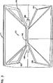
図1は、本発明によるマイクロウエーブバッグ構造の、使用時における開かれた膨張前の概観を示す図である。
図2は、図1に示された構成の側面図であり、マイクロウエーブポッピング動作の過程における膨張の後であって、ポップされたポツプコーンへのアクセスのためにオープンされる前の状態を示す図である。
図3は、図2に示した構成を端面側よりみた図である。
図4は、図1の4−4ラインに沿って得られる断面図である。
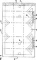
図5は、図1及び図2の構成が折り畳まれるブランクの内側面を示す平面図である。
図6は、図3に示したブランクの底面を示す図である。
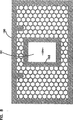
図7は、図5に示したブランクの層の間に配される接着剤パターンの模式図である。
図8は、図7に示される接着剤パターンの変形例を示す図である。
図9は、図5、図6によるブランクのロールストックを準備するためのプロセスを示す模式図である。
図10は、ブランクのロールストックを準備するためのプロセスの変形例を示す模式図である。
発明の詳細な説明
I 従来のシステムにおける特有の不具合点
一般的なマイクロウエーブポップコーンバッグの構造は2層構成であり、それらの間に積層用の接着剤が適用される。一般的には、積層用接着剤は2つの層の間の全体にわたって塗布される。このことはいくつかの不具合をもたらす。例えば、接着剤のコストという点において、比較的高価なものとなる。
第2に、パッケージにかなりの重量が加わることになる。これは、運搬のような実務上の観点から望ましくないことである。また、さらに、パッケージングにおける大きな重量は膨張のためにより多くの熱/蒸気圧を必要とするので、作用上の観点からも好ましくないことである。
また、層間における多量の接着剤は、構造物の全体にわたって堅さを加える。これは使用において、ふくれる、或いは膨張するといったその構成の能力を減少させるものである。
II 本発明によるプロセスおよび材料の特定の原理
本発明によれば、多層のバッグ構造における層間の全体領域にわたって接着剤を塗る代わりに、接着剤をあるパターンで塗る。そのパターンは、好ましくは、層間における接着剤の総量を少なくとも重量で35%減少させる。また、好ましくは、全体の重量を40〜70%減少させる。
以下に述べる、より詳細な説明によって明らかになるように、ある特定の構造において、ある特定の場所或いは領域に接着剤のライン状のパターンが用いられる。そして、その接着剤のパターンが位置するところで単位面積当たり70%減少した接着剤が用いられるようにパターンが選択される。好ましい構造において、他の部分或いは領域においては、接着剤がその領域の全体に塗布される。
III 本発明に従った改良を含むポップコーン用のマイクロウエーブパッケージ
図1において、1はマイクロウエーブポップコーンパッケージであり、本発明による種々の長所を備えたものである。図1において、パッケージ1は使用のために保護用の梱包材より取り出され、消費者によってマイクロウエーブオーブン内に置かれたときの様子を示すものである。この段階に先立って、パッケージ1のごときパッケージは、ほぼ折線A,Bのところで折り畳まれて、3つ折りの状態で貯蔵され、販売される。その3つ折状態において、当該構成物は不図示の保護用湿気バリアの梱包材で梱包されて販売、貯蔵される。これらのことは、一般に広範な種々のマイクロウエーブバッグに利用されている。
マイクロウエーブポップコーンパッケージ1は柔軟な外側バッグ2を備え、この外側バッグ2はポップコーンの内容物、すなわちポップコーンと油脂をその中に含む。使用において、マイクロウエーブエネルギにさらされる間、ポップコーンはポップされ、バッグは膨張する。このことは、例えば、米国特許第5,044,777号および米国特許第5,081,330号に記載されており、これらは本願に参照のために組み込まれるものである。なお、この意味において、「柔軟」とは、使用の間にバッグの膨張を妨害するほどに、好ましくないほどに堅く堅固ではないバッグ材料を意味する。換言すれば、この用語は、容易に折り畳まれたり伸ばされたりされ得る材料を意味するのに用いられる。
ポッピングの前に、ポップコーンはバッグ2の中央領域5に保持される。この領域において、ポッピング前のポップコーン内容物はマイクロウエーブ相互作用構造の直上に配置される。ポッピングの間、ポップコーンカーネルの内部の湿気がマイクロウエーブのエネルギを吸収し、ポッピングのための十分な蒸気と熱を生成する。更に、マイクロウエーブ相互作用構造はマイクロウエーブエネルギを吸収して熱を発散し、ポッピングを促進する。好ましい構造において、マイクロウエーブ相互作用構造は中央領域5を占めるが、ポップコーンパッケージ1の他の部分には実質的には延びていない。すなわち、マイクロウエーブ相互作用材料の配置は、ポップコーン内容物に近接し、ポップコーン内容物によって大部分が覆われる領域に限定されている。これは、少なくとも、マイクロウエーブ相互作用材の効率的な利用をもたらすという点で好ましいことである。また、ポッピングの過程に関連して、好ましい熱伝達と熱保持をもたらすという点においても好ましいことである。
次に、図4を参照する。図4は、図1の4−4に沿った断面図である。図4を見ると、ポップコーンパッケージ1は第1と第2の対向するパネル20、21を備え、それらが第1および第2の対向する横ガセット22、23でつながれていることがわかる。
ガセット22、23はポップコーンパッケージ1を第1と第2の膨張可能なチューブ28と29に分ける。ポップコーンの内容物30は、初期状態ではチューブ29内に配置され、実質的にその中に保持される。チューブ28は、ポッピングに先立って、折り畳まれている。実際、好ましい構造において、チューブ28はマイクロウエーブオーブン内において加熱されるまでは、閉じた状態を保つように一時的な熱シールによりシールされている。更に、図4を参照すると、横ガセット22は折り端部33と34、及び内側に向いた中央折り畳み部35を備える。同様に、ガセット23は折り畳み端部38と39、及び内側に向いた中央折り畳み部40を備える。
図4に示される構成とするために、パッケージ1は、多層(すなわち2層)のブランク(典型的には、12インチ×21インチ、すなわち、30.5×53.3cmの大きさを有する)から折り畳まれて得られる。こうしてパネル20は中央の縦方向の継ぎ目42を含む。33、34、35、38、39及び40のような折り畳み部は、柔軟なマイクロウエーブパッケージングのために広く用いられる。例えば、それらは米国特許第5,044,777号、米国特許第5,195,829号に示されており、また、そのような折り畳みを利用した製品としては、本願の出願人であるゴールデンバレーマイクロウエーブフーズ社(ミネソタ州、エディナ)製の商品名ACTII▲R▼がある。折り畳み部33、34、35、38、39及び40は、とりわけガセットパネル48、49を特定する。
ポップコーン内容物30は、ある場合にはポップ前のカーネルを備え、またある場合には味付けされたポップ前のカーネルを備え、またある場合ではポップ前のカーネル及びオイル/ファットの混合物を備える。内容物30がポップ前のカーネル(味付けされていてもいなくても)とオイル/ファットの混合物を備える場合、ある構成においては、オイル/ファットはおよそ105°Fで液化される材料であることが好ましい。そのような条件のもとでの好ましい構成においては、オイル/ファットの重さに対するカーネルの重さは2:1〜20:1の範囲であることが好ましい。
構造物1は、ポップコーン内容物30の直下にマイクロウエーブ相互作用構造、すなわち感応材45を含む。マイクロウエーブ相互作用構造45は一般的なマイクロウエーブ相互作用ストック(stock)である。ここで記述されている特定の多層(2層)構造1においては、マイクロウエーブ相互作用構造45は層の間、すなわち層46、47の間に配置され、柔軟な構造物1として折り畳まれる。
本発明による構成のための好ましいマイクロウエーブ相互作用構造物について以下に説明する。好ましくは、マイクロウエーブ相互作用構造が以下に説明するような積層物である場合、その構造物は図1に示す折線AとBをいくらか超えて延びている。好ましくは、それは、開放可能な上端部90に向かって折線Bを超えておよそ0.4〜1.0インチ(1cm〜2.54cm)延びている。また、底端部93に向かって、折線Aを超えておよそ0.25〜0.5インチ(0.63〜1.27cm)延びている。上部の開放可能な端部90に向かう方を、底部の閉端部93に向かうものよりいくらか長くするのは、次の理由による。すなわち、一般に以下で説明する底端部におけるVシールは、以下に説明する上端に近接するVシールよりもいくらか大きいことによる。
再度、図4を参照する。図4に示す構造において、マイクロウエーブ相互作用構造45は2つの層を備える。すなわち、柔軟なマイクロウエーブ透過性の重合材(polymeric material)45aと、その上に配置されたマイクロウエーブ相互作用性金属材45bの領域である。もし、折り畳み部34、39の周りで熱を発生させることが望ましいのであれば、マイクロウエーブ相互作用材はこれらの領域まで延ばすことができる。また、金属が、折り畳み部34、39の周りで折り畳まれうる重合体の重合化された部分の表面全体を覆う必要はない。
次に図5を参照する。図5はパネル、シート或いはブランク60の上平面図であり、この材料が折り畳まれて図1及び図2に示されるような構造物が形成される。図5に示される特徴の多くは一般に知られたものであり、例えば米国特許第5,195,829号及び5,044,777号に記載されている。
図5に示されるのは、しばしば、パネル60の裏側と称されるものである。すなわち、パネル60の61側の面であり、これは、図1で示される組み上げられたバッグ構造1の内側表面を形成する。一方、図6の62で示されている、図5で示される側と反対側の面は、しばしば表側とも称され、バッグ構造1の外表面を形成する。このパネル60は柔軟なシート材を備え、図5に示されるように、これを折り曲げて構造物1が形成される。そして、パネル60を所望の形状に形成するために、パネル60には種々の接着剤領域が設けられる。
更に、図5において、仮想線63は領域64を特定しており、この領域64には、感応構造物45のようなマイクロウエーブ相互作用構造の少なくとも一部が関連付けられる。また、仮想線63で特定される周辺を有した領域は、使用時に、最終的にポップコーン内容物が位置することになる面61上の位置を示す。図4に示す相互作用構造45のようなマイクロウエーブ相互作用構造は、構造物1の内面上に、或いは外面上に、或いは層の間のいずれに配置されてもよい。図1や図4に示したような好ましい実施形態では、マイクロウエーブ相互作用構造45は層の間に配置される。
図5において図示されている面61は、パッケージ1が折り畳まれたときに当該構造物の内面を形成するものである。ポップコーン内容物30(図4に示される)は、結果的に線分63で特定される中央領域64を覆うように配されることになる。
更に図5を参照すると、線66は図4の折り畳み部34を形成する部分を示す。そして、線67は図4の折り畳み部39を形成する部分を示す。同様に、線68は折り畳み部40(図4)に、線69は折り畳み部35(図4)に、線70は折り畳み部36(図4)に、線71は折り畳み部33(図4)にそれぞれ対応する。折り畳み線68と66の間の領域75は、最終的に図4のパネル49を、折り畳み線67と69の間の領域77は結果的に図4のパネル48をそれぞれ特定する。
図5を参照すると、折り畳み部分A及びB(図1)は、線81と80に沿った折り畳み部分を形成するように、最終的に構造物全体を折り畳むことによって形成される。この最終的な折り畳みは、図1及び図2に示されるバッグ構造が組み立てられた後になされる。
次に図6を参照する。図6は、図3のパネル60を裏返した状態を示している。図6におけるこの方向の故に、端部82と83は図5のものに対してひっくり返っている。シール領域(sealant area)84は、折り畳みの過程(熱シールを伴う)において、領域85(図5)と結合するのに用いられ、縦長の継ぎ目、或いは図4のシール42を形成する。
図5を参照すると、折り畳みの過程(熱シールを伴う)で、領域89の各部分が図1の端部シール93を形成するために互いに結合され、領域92の各部分が図1の端部シール90を形成するために互いに結合される。端部シール90は構造物の「上端部」に配され、その大きさと構造は、当該構造物の使用中において、内部の蒸気圧によって排気が行われ得るようになっている。一方、端部93は下端部を形成し、使用の間もシール状態を保つ。消費者によるポップコーンへの典型的なアクセスは、上端部90を介してなされる。この点については米国特許'777において記述されているものでもあるが、図2と図3に関連して後述することとする。
図6のパネル60の下側における密封領域95と96の各々の部分は、折り畳み線68によって折り畳まれるとき(熱シールを伴う)、互いに結合(オーバーラップ)する。これは、折り畳み後において、パネル60を確実に好ましい形状とすることを助長するものである。これは、米国特許第5,195,829号の図1(a)の構造における、密封領域82及び84においてなされていることと類似のものである。同様に、図6におけるパネル60の下側にある密封領域98、99も、折り畳み線69付近でパネルが折り畳まれるときに、(熱シールにより)互いに結合する。
再び図5を参照する。密封領域103、104、105、106、107、108、109及び110はVシール或いは斜めシールと呼ばれるものである。類似の領域は、米国特許第5,195,829号の図1の参照番号64〜67で示されている。折り畳まれた状態で、領域103〜110は互いに結合(オーバーラップ)し、パネルの選択された領域を相互につなぎ合わせた(tack)状態(熱シールによる)に維持し、バッグの膨張の過程において好ましい形状を提供する。特に、折り畳みの過程(及び熱シールの過程)において、領域103は領域104と、領域105は領域106と、領域108は領域107と、領域110は領域109とそれぞれ結合する。領域105と106の間の結合、及び領域108と107との間の結合は、3つ折りに折り畳まれた状態でポップコーン内容物が配されない領域において、図4に示されるパネル48及び49の選択された部分がパネル21へ固着された状態を維持するのに貢献する。領域104への領域103のシール、領域109への領域110へのシールは、3つ折りの状態において、図4のパネル116及びパネル115がパネル20に対してシールされた状態を維持するのを助長する。これは、図4のポップコーン内容物30が実質的に所望の部分に維持されることを確実にするものである。このことによる利点は、米国特許第5,195,829号において記述されている。
再び、図5を参照し、密着領域120、121、122および123について説明する。折り畳み線66において構造物が折り込まれると、密着領域120は密着領域121に結合(オーバーラップ)する。また、当該構造物が折り込み線67で折り込まれると、密着領域123は密着領域122と結合(オーバーラップ)する。更に、領域120と121の間の結合後(熱シール後)はパネル49がパネル21にシールされることをより確実にする。また、領域123と122の間の結合はパネル48がパネル21にシールされることを保証する。これは、米国特許第5,195,829号の図1の領域68、70、71、72の利用に類似のものである。領域105、106、107、108、120、121、122及び123は図1の中央部分5が、使用中においてバッグが膨張する過程で比較的平坦に維持されることを助長する。
次に領域128、129、133及び134について説明する。これらは、図4のパネル116及び115がパネル20にシールされることを確実にするために用いられる。これにより、ポッピング前のポップコーン内容物30がチューブ29内に維持され、所望された加熱が行われるまで、実質的にチューブ28には入り込まない。特に、領域128と129は、構造物が折り込み線70で折り込まれたときに互いに結合する(オーバーラップ)するようになっている。また、領域133と134は構造物が折り込み線71のあたりで折り込まれたときに互いに結合する(オーバーラップ)するようになっている。同様に、領域103と104の間、領域109と110の間の結合は、蒸気が生成されポップコーンがポップするのに従ってバッグが膨張を開始するまで、チューブ28が折り畳まれた状態を維持することを確実にする。所望であれば、パネル116と115がパネル20に対してシールされることをより確実にするために、領域126と127、及び領域131と132が用いられ得る。
領域128、129、133及び134に関するタイプのシールは、従前の構造で用いられていたものである。たとえば、米国特許第5,044,777号の図1における42、44、46及び48が用いられ得る。
端部シール90、93や、領域103、104、105、106、107、108、109、110、120、121、122、123、128、129、133および134を含むシールに用いられる材料としては、好ましくは、一般的な熱シール装置を用いて機能させ得る熱シール可能なものが用いられる。すなわち、単なる接触のみではシール性は生じず、いくらかの熱の付与を必要とする。これを行うものとして、たとえば熱シール装置の加熱あご(heating jaw)が挙げられる。これはいくぶんかは好ましいことである。なぜなら、それは、使用されるシール材料が、印刷装置に用いられ得るような、ロールスタックに適用され得るるからである。ロールスタックは、こうして、互いに接着してしまうような種々の層を持たずに、巻き上げられる。
次に、図2を参照して説明する。図2は図1及び図4に示された構成が、マイクロウエーブポッピングの過程において膨張した後の外観を示している。パッケージ1は対向する端部150及び151を含む。端部150は図5の端部60aに対応するものであり、端部151は、図5の端部60bに対応するものである。
図3は端部151側から見た状態を示す図である。図5及び図6によって説明した接着剤パターンにより、図3で示す構造1には4つのタブもしくは耳160、161、162、163が形成される。ポッピング後の排気が領域165で生じる。ポッピング過程の後、対角線上に配列した2つの耳、例えば耳160と162或いは耳161と163をつかむことにより、消費者は図3の構造1を開けることができる。すなわち、それらを引き離すように引っ張ることによりパッケージ1は開けられる。他の方法も当該パッケージングをオープンするのに用いられ得るが、上記した方法が、このような構造においてポップされたポップコーンを獲得するためのアクセスとして、典型的な消費者によって採用される手法であると思われる。また、このような方法は、パッケージの内部から逃げ出てくる蒸気/熱の直接的な経路に指を置くことを避けられるので好都合でもある。
IV 本発明による改良
再び図4を参照すると、全体に渡りパッケージ構造は2つの層を備え、バッグ1を形成するために適切に折り畳まれる。図5、図6に示されるパネルは類似の材料の耐脂性のクラフト紙からなる2つのパネルを備えている。そして、それら2つのパネルの間には、マイクロウエーブ相互作用構造が配されている。図4に示される断面において、これらのことは明瞭に示されている。
図4によれば、マイクロウエーブ相互作用構造45は、少なくとも特定の選択された部分に付着されている、金属のごときマイクロウエーブ相互作用材45bを有する重合体シート45aを備える。なお、典型的には、マイクロウエーブ相互作用材45bは重合体シート45aの一方の面のみに付着されている。そして、それは、その構造の中にあって次の2つの形態のうちの1つに方向づけられている。すなわち、内側層46に向かって金属を配するか、外側層47に向かって金属を配するかのいずれかである。いずれの構成も可能である。しかしながら、図4に示したような、層46に向かって金属を配するほうが概して好ましい。
本発明は2つの層46と47の間に適用される接着剤パターンに関する。この点に関して、図7を参照して説明する。
図7には、図5及び図6に示すようなパネル構造の外側層180が示されている。これは図4の層47に対応するものである。図7において、パネル180上の好ましい接着剤のパターンがグレー領域で示されている。白い領域は、いかなる接着剤(adhesive、glue)も提供されない部分からなる。
図7によれば、パネル180は中央領域181を含み、この中央領域181ではその全体にわたって接着剤を有する。領域181は、マイクロウエーブ相互作用構造におけるマイクロウエーブ相互作用材によって覆われる領域と同程度の大きさを有する。こうして、それは、マイクロウエーブ相互作用材とのオーバーラップ領域、或いは部分を構成する。特に、マイクロウエーブ相互作用構造が重合体の裏当て上に付着したアルミニウム金属を備える場合、図7の181で示される領域は少なくとも感応材としての金属部分と同じ大きさか、好ましくは少し大きいサイズを有する。このように、層180が感応材をその間に有して第2層に固定されるとき、その感応材は領域181内にその金属部分が当てはまるように配置される。外側層を表す図7における特定の構成は、マイクロウエーブ感応材の重合体の裏当てが外側層に向けて配置され、かつ、マイクロウエーブ相互作用領域、すなわち金属が内側層に向けて配置されるという状況下における使用において好ましい。こうして、組立の過程において、層180とマイクロウエーブ相互作用材の実際の金属部分との間に、その感応材の重合体シートが配置されるようになる。このようにして、層180は、図4の断面図において示されるような構造において用いられることになる。
更に図7を参照すると、参照番号182は外側の境界部分を表し、この境界部分も接着剤で完全に覆われている。境界182は、好ましい実施例においては、全体を通しておよそ0.625から1.125インチの幅(1.5から2.86cm)である。これは、2層構造の積層シートにおける剥離の防止を促進するものである。
更に、図7において、参照番号184は、パネル180の多大な部分に設けられる接着剤パターンを示している。パターン184は、好ましい構成において、「ストリーム(stream)」もしくは「ライン」で形成され、好ましくはその幅はおよそ1/16”(0.06インチ)以下であり、典型的にはおよそ1/32”から1/16”の幅である。すなわち、およそ0.15cm以下であり、典型的には0.07から0.15cmである。好ましくは、そのラインパターンを有する領域においては、接着剤の平均の被覆率は当該パターンが存在する領域のおよそ10〜50%であり、好ましくはおよそ10〜20%である。こうして、これらの領域において、領域全体を覆うように接着剤(glue、adhesive)が塗られる場合よりも、好ましくは50〜85%少ない接着剤で済むようになる。
種々のパターンが用いられ得るが、「規則的な」幾何学的パターンが好ましい。弱い部位の発生を防止できるからである。典型的で、かつ好ましいのは、正多角形、すなわち、各辺の長さが等しい多角形である。ここでは正六角形パターンを用いる場合を示しているが、これに限定されるものではない。たとえば、ひし形や矩形等のパターンがその代わりに用いられ得ることは明らかである。なお、正六角形は共通の直線的なエッジを有するようには配列されていないので、パターンの端部においては、正多角形の断片化が生じている。この断片化は多くの本発明に従った典型的な応用において用いられ得るが、これに限定されるものではない。
次に図7の185、186で示される領域を説明する。第2のパネルがマイクロウエーブ相互作用構造を間に挟んでパネル180に積層され、その構造物がバッグ形状に折り畳まれた後、その構造が使用によって膨張した状態となったとき、185と186で示される領域は、図3の仮想線で示された185と186の領域における2つの層の間でかつ外側層180の直下である領域となる。これらのタブ(tab)は、これらの位置にあって2つの層46と47(図4)を補強し、ポッピング処理の後、消費者によって図3を参照して上述したような通常の方法でバッグが開けられるとき、その開口操作を促進する。すなわち、領域185及び186におけるこの連続的な接着剤の領域は、この位置における積層された層の積層強度を向上するのに貢献する。このことは、バッグ1を破壊することなく開放することを容易とするので、有利である。
再び図7を参照すると、タブ186と185はおよそ1インチ×1.5インチ(2.5×3.8cm)の領域を有し、典型的かつ好ましくは、およそ0.5〜1.5インチ(1.27〜8.8cm)×1.0〜2.0インチ(2.5〜5.1cm)である。その領域は、外側の境界182の、図5に示されるエッジ165に対応するエッジに沿った部分に近接して配置される。そしてそれらは、図4に示したような中央部へ向かうガセットの折り畳み部分35と40を越えて、これらに跨がって延びている。好ましくは、各々は、対応するガセット折り畳み部分がその中心に配される。
好ましい構造において、接着剤は、それが配される領域において、およそ5〜6 lb/reamの量で塗られるべきである。接着剤の塗布には種々の方法が使用できる。たとえば、フレキソグラフィック印刷(flexographic printing)やグラビア法(gravure methods)のようなものが挙げられる。なお、ここで、およそ5〜6 lb/reamの量で塗られるべきであるという場合、それは、接着剤が適用される特定の位置に関して述べるものである。それら特定の位置とは、領域181、182、185、186及び複数のライン184である。従って、上記表現は、接着剤が配されていない位置を考慮に入れて得られる全領域における接着材の平均を意味しているものではない。
本発明による構造においては種々の接着剤が使用可能である。積層用接着剤として好ましい接着剤はDuracet12である。実際に、ここで記述されている発明は、Duracet12を用いるのに特に良好に適応される。
図7は好ましい接着剤パターンの縮尺図(scale depiction)である。よって、もしも典型的なパネルがおよそ12インチ×21インチ(すなわちおよそ30×53cm)で形成されているのであれば、尺度を大きくして、図7で示したのと同一のパターンが使用可能である。
次に、図8を参照する。図8に示されるパネル190は図7で表したパネル180に類似のものである。図8に示されるパネル190は、図7の領域181との比較において領域191におけるパターンが異なるという点を除いて、図7に示した接着剤パターンと同一の接着剤パターンを有する。図8の領域191におけるパターンは、外側境界193と中央領域194で示され、中央領域194には接着剤は存在しない。図8は、マイクロウエーブ相互作用構造のエッジ部に対し良好な接着結合を形成するのに使用し得る。しかしながら、マイクロウエーブ相互作用構造の領域における積層は、図7に示される構造におけるもののほうが図8に示される構造におけるものよりも良好である。これは、図7におけるその領域でより多くの接着剤が用いられ、その領域の全体を覆うからである。概して、図7の方が、たとえば、美的観念等の、種々の理由によって好ましいが、両方ともに機能し得る構造である。
ここで、接着剤によって内側層が外側層に接着され、そして、接着剤が、少なくとも第1の領域において、例えば層の一方である第1層の該第1領域に対応する表面積のおよそ50%を越えない領域を被覆するライン状パターンを有した接着剤パターンで塗られるという場合、その第1領域はそのライン状の接着剤パターンを有する部分を意味し、接着剤が塗られる層の面の全体を意味するものではない。例えば、図7において、そのような特徴的構成は6角の多角形を有する領域に関する部分であり、接着剤で完全に覆われている領域ではない。そして、そのような構成は、例えば図7及び図8に示されるような、層の1つの周辺に沿った外側境界を含んでいてよい。また、その構成は、例えば図7の参照番号181で示されるような、或いは図8の参照番号193で示されるような、中央マイクロウエーブ相互作用構造オーバーラップ領域を含んでよい。図8の193で示されているものは、例えば矩形状に接着剤が連続的に塗られたパターンというよりは、接着剤の境界193を有する中央マイクロウエーブ相互作用構造オーバーラップ領域として特徴づけられる。こうして、図8の構成は、中央の非接着剤領域を有する矩形枠状の接着剤パターンを含むものである。
本発明に従った原理は、接着剤が外側層に塗られ、マイクロウエーブ相互作用構造が重合体の面を介してそれに固定される構造、或いは接着剤が内側層に塗られ、マイクロウエーブ相互作用構造の重合体の面がそれに固定される構造において利用され得る。このように、いくつかの実施例においては、図7、図8の接着剤パターンは外側ではなく内側の層に塗られる。
V. 好ましい構造を用意するためのプロセス
図9は、好都合なマイクロウエーブバッグ構造を作るためのロールストックを準備するための、本発明による好ましいプロセスを実施する模式図である。広範な種々の技術及び方法が所望のロールストックを準備するのに用いられ得ることが理解されるであろう。図9、およびこれに関連する説明は、使用可能な技術の一例として示されるものである。図9に示されている動作の多くの特徴は、一般的なパッケージングを製造するために既に用いられているプロセスに対する簡易な変形によって得られるものであるという理由に基づくものであり、これ以外の理由に関しては必ずしも好ましいというものではないかもしれない。
図9を参照すると、同図に示される概要に従って準備されるロールストックは、2層の紙を有し、その2層の紙の間にマイクロウエーブ相互作用材料が配置された材料からなるものである。そして、図9において準備されたロールストックは、図1や図4において示されたような構造物を形成するのに用いられることになる。
図9を参照すると、本プロセスに従って準備された最終的なロールストック材料は280で示されている。3つの供給ストック材料が用いられ、それらは285、286、287で示されている。
供給ストック287は、本発明にしたがったプロセスにおける使用に先立って準備された、マイクロウエーブ相互作用構造を備える。こうして、供給ストック287は連続的な金属化された重合フィルム(polymeric film)を備える。典型的な好ましい構造において、金属はその重合フィルムの一方の側に付着(deposit)されて配置される。金属フィルムはそれが設けられた側の面全体を覆う必要はなく、パターン状に存在していてよい。
286で示される供給ストックは、組み立てにおいて、バッグの内側の層に対応する層を形成する材料を備える。ここで記述される特定の応用において、それはクラフト紙であってもよい。また、ある応用例においては、それは防油脂性の紙である。
供給ストック285は、外側の層を形成する材料に対応する。そして、これは典型的には、漂白されたクラフト紙である。これは最終的には、図7に示す層180に対応する層、或いは図9に示す層190を形成することになる。ある応用においては、それは最終的に印刷が施されたりするので、しばしば機械的なつやだし仕上げ(machine glazed finish)が施される。また、ある応用において、それは、耐油脂性の提供ためにフッ素化学処理(fluorochemical treatment)された材料である。また、他の例ではフッ素化学処理がなされていない。
図9において、仮想線290は当該プロセスの第1段階、すなわち第1ステージを特定している。この段階において種々の供給ストックが互いに積層され、連続的な供給材、すなわちウエブ193が形成され、下流工程へ送られる。
第1ステージ290において実行されるプロセスは以下のようである。マイクロウエーブ相互作用材料の連続的な供給ストック287がステーション295へ供給され、同時に供給ストック286もステーション295へ供給される。ステーション295において、これら2つは互いに積層される。そして、ステーション295において、ナイフもしくはカッターが、供給ストック287から供給されたマイクロウエーブ相互作用材料の選択されたピースへカットするのに用いられ、カットされた材料は連続的な紙296上へ位置決めされる。このカッティングのための一般的な構成としては、米国特許出願08/388,755号の図11に模式的に示された構成が使用可能である。また、ステーション297では、供給ストック286からの紙の供給296を受け、積層されるべきマイクロウエーブ相互作用構造の受け入れのために適切な場所に接着剤が供給される。好ましくはマイクロウエーブ相互作用材は、その一方の面に金属層が付着された重合材のシートを備えている。好ましくは、そのマイクロウエーブ相互作用材は、ウェブ296と重合材のシートの間に金属層が配置されるように、ウエブ296に固着される。
好ましくは、ステーション297で適用される接着剤はエチレンビニルアセテート共重合体接着剤(ethylene vinyl acetate copolymer adhesive)である。使用可能で、商業的に入手可能な製品は、H.B. Fuller(Vadnais Heights, Minnesota)製の製品番号WC-3460ZZである。
ステーション297においては、フレキソ印刷(flexographic)もしくはグラビア印刷(gravure)のような印刷技術がこの接着剤を塗布するのに用いられ得る。
更に第1段階(290)を参照すると、300はロールストック286から連続的に供給された紙であり、その上に、供給ストック287から供給されたマイクロウエーブ相互作用構造のパッチが設けられ、これはステーション301へと向かう。また、これと同時に、供給ストック285からの紙原料が連続的なウエブ304としてステーション301へ向かうことが示されている。ステーション305においては、積層用接着剤がウエブ304に塗布(適用)される。この積層用接着剤は、例えば、フレキソ印刷もしくはグラビア印刷技術を用いて適用されてもよい。積層用接着剤は、本発明による、好ましいパターンで塗布さなければならない。
ステーション301において、結果として得られる構造の全体にわたる層を形成することになるウエブ300は、ローラバイト(roller bite)を通して、やはり結果として得られる構造の全体にわたる層を形成することになるウエブ304へ圧迫、積層され、これら紙シートの層の間にマイクロウエーブ相互作用材料が配されたウエブ293が形成される。
310において、プロセスの段階は、接着剤の乾燥を促進するために用いられ得るホットローラ311を含む。ただし、このような段階はオプショナルである。312において、ウエブがこのオプショナルな段階にある状態が示されている。
本プロセスにしたがって準備されたウエブから作られるパッケージの外側には、印刷或いはグラフィックを提供することが望まれる。これはウエブ312を、313で示される印刷プレス(第3段階)を通すことにより実現される。マルチカラー印刷やグラフィックを提供する装置を含む、広範な種々の印刷プレス装置が用いられ得る。314は、印刷プレス313から出てきた連続的な印刷されたウエブを示す。
ウエブ上に所望の徴(indicia)が印刷され、および所望の耐油脂性処理が適用されてプレス313から出た後、連続的なウエブ314は前乾燥機315へ向かう。乾燥機315では、インクや耐油脂性処理材が乾燥される。典型的には、乾燥機は温風乾燥システム(forced-air dryer system)であり、およそ150°F〜250°Fで稼動する。乾燥機内への滞留時間は、ウエブにとって好ましいレベルの乾燥を得るのに十分な時間であればよい。典型的には、ウエブの温度が150°F〜190°Fとなるのに十分な滞留時間であることが好ましい。
典型的な態様においては、この時点において、バッグを組み上げるときに用いられる所望のシールを形成するための熱シール接着剤のパターンを、ウエブの対応する表面上に適用する必要がある。これらは図5及び図6で示された密着領域に対応する。図9の模式図において、このステップはステーション320において実行される。熱シール接着剤は、例えばグラビア印刷やフレキソ印刷等を用いた、一般的な技術によって塗布され得る。
321において、連続的なウエブが示されている。ここで、ウエブには熱シール領域が形成され、最終乾燥機325へと供給される。最終乾燥機において、熱シール接着剤は乾燥され、インクの最終的な乾燥が生じる。これは、典型的にはおよそ250°F〜400°Fに設定された、温風乾燥機システムによって即座に実行される。
326は完成した連続的なウエブを示し、これは最終的なロールストック280へ向かう。
図9で示したようなプロセスは、印刷されたロールスタックを準備することができる。ここで、最終的なロールスタック280上では、1つ以上のシート或いはバッグが互いに近接して配置される。これは、後に分離もしくは切り離され、個々の流れとなって連続的なバッグ形成部へ供給される。好ましいロールスタック280を形成するための、ウエブ上へ連続的に印刷されたバッグのブランクを配置する有用な方法は、(印刷時におけるローラーによって)90度回転したオフセットを有してバッグの印刷パターンを横並びにすることである。これは本システム、特にアニロックス(anilox)がプレートへインクを運ぶようなシステムの円滑な動作を確実にする。
次に図10を参照する。図10は、全体として図9に類似しており、図9の構成と類似の動作を行う部分には同一の参照番号を付してある。図10の構成においては、熱ローラやホットカンシステムを用いること(図9の310で示される構成)に代えて、温風乾燥システム330が用いられる。この温風乾燥システム330では、およそ100°〜200°Fの温風を用いて乾燥を行うことになるが、この点については、主に選択された接着剤の特性や滞留時間に依存する。
VI. 好ましい材料
好ましい材料は、個々の実施形態に依存するものであろう。目下、好ましい材料は以下の通りである。
図1〜図4の2層もしくは多層の構造に関して、マイクロウエーブ相互作用材料の好ましいロールストック(rollstock)は、Hoechst Celanese 2600 60ゲージのポリエステルフィルムにアルミのフィルムが真空蒸着されたもので、Tobias濃度計によって測定された光濃度値(optical density)が0.25±0.05を与えるものである。そのような材料は、Madico(Woburn, MA 01888)より準備及び入手される。
2層構造に関し、熱シールパターンを形成するのに用いられる好ましい熱シール用接着剤は、ポリビニルアセテートホモポリマ接着剤である。この例としては、Duracet12があり、これはFranklin International, Inc.(Columbus, OH)より入手できる。そのような材料が使用される場合、シールは、熱シール装置の加熱あご(heat jaw)を用いた一般的な方法で形成され得る。
図1から図4に示す2層構造において、マイクロウエーブ構造の金属側をこれに隣接する紙に固定するのに好ましい接着剤は、パッケージにおいてマイクロウエーブ相互作用構造に用いられる一般的な積層用接着剤である。好ましいものは、エチレンビニルアセテートコポリマ接着剤であり、これは例えば、H.B.Fuller Company(Vadnais Heights, MN)から入手できる製品番号WC-3460ZZである。
図4から図5に示される2層構造において、内側層に用いられるウエブが防油脂性の紙である場合、好ましいウエブはおよそ25ポンド/reamを越えない基本重量(basis weight)を有する柔軟な紙であり、好ましくは21〜25ポンド/reamの範囲のものである。そのような例においては、スコッチバン▲R▼テストの下で最小のキット8の耐油脂性を有する、FC807(フッ素化学)処理が施された紙が好ましい。使用できる材料としては、Rhinelander Paper Company(Rhinelander, WI 54501)より入手できるRHI-PEL250がある。FC807は、3M社(St. Paul, MN)による化学処理剤である。なお、この紙に関して、防油脂性であることがより重要であるという事実にも関らず、内側層が耐油脂性を有することも好ましいものである。その理由は、内側シートの紙の表面における脂の染みが外側層を介して観察され得るものであり、その染みが顧客にとって不快なものであるからである。こうして、内側層の処理、特にその外表面の処理は、好ましいものである。
たとえば、図7や図8に示した層間のパターンのような、好ましいパターンに適用される接着剤として用いるための好ましい材料はDuracet12である。それは、好ましくは、印刷位置において、およそ5〜6 lb/reamの量において適用される。それは、例えばフレキソ印刷やグラビア印刷技術のような種々の印刷技術を用いて適用することができる。 Field of Invention
The present invention relates to materials and packaging for use as an inflatable bag structure for microwave popcorn popping.
Background of the Invention
The structure for popping of many microwave popcorns that is commonly used commercially is a multi-layer paper bag. In this multi-layered paper bag, inner and outer paper sheets are laminated to each other, and a microwave inductive structure (also referred to as a microwave sensitive material) is sealed between the paper layers. Such popcorn popping bags are described, for example, in US Pat. Nos. 4,904,488, 4,973,810, 4,982,064, 5,044,777, and 5,081,330, the disclosures of which are incorporated herein by reference.
A common feature of the structures disclosed therein is that they are made entirely of flexible paper material. In this configuration, the structure is sufficiently open to expand and expand conveniently under vapor pressure when the popcorn contents contained therein in the microwave oven are exposed to microwave energy. Be flexible. Also, these materials are sufficiently flexible so that the sheet is formed into a folded shape, for example in the course of a continuous bag manufacturing process.
Many microwave products contain a pre-pop popcorn kernel and fat / oil (ie fat) or flavor (eg salt) in the bag. During storage and transport, especially in relatively hot environments, the material stored in the bag can dissolve and leak out of the bag structure. Some leakage can occur if the stored material contains some fluidity or liquefied oil / fat even if it is not at a relatively high temperature during storage.
Further, in typical popcorn microwave cooking (especially when the popcorn content includes oil / fat), hot liquid oil or fat is produced. If the structure holding the popcorn is made of paper, the paper used will be sufficiently resistant to hot liquid oil / fat stains and passages in order to obtain a satisfactory product function during the microwave cooking process. Must have. For example, when microwave cooking (ie popping) is taking place, oil / fat should not leak from the structure. This is because it provides a very undesirable, greasy feel and appearance on the outside of the package.
Summary of invention
According to the present invention, a microwave popcorn package or bag is provided. The bag comprises a flexible bag structure comprising an inner layer and an outer layer and a microwave interaction structure disposed between the inner layer and the outer layer. Here, the microwave interaction structure has a front surface and a back surface, and the inner layer is bonded to the outer layer with an adhesive. According to the invention, the adhesive is applied with an adhesive pattern at least in the first region, the adhesive pattern of this first region being the first of the first layer which is one of the layers. Cover an area that does not exceed approximately 50% of the surface area of the area. In the first region, the adhesive pattern is preferably a regular polygonal pattern, typically and preferably having a hexagonal pattern. In one particular configuration, as a second region, the adhesive pattern includes a first outer boundary of adhesive along the outer periphery of one of the layers. This outer boundary preferably comprises a peripheral boundary having a width of 0.625 to 1.125 inches (1.59 to 25.86 cm).
In certain preferred configurations, the adhesive pattern includes a third region that overlaps the central microwave interaction structure. The overlap region is disposed on the region having a width that is 0.125 inch to 0.5 inch (0.31 to 1.27 cm) larger than the width of the microwave-sensitive material disposed on the region. It is a rectangular pattern having a length that is 0.125 inch to 0.5 inch (0.31 to 1.27 cm) larger than the length of the microwave sensitive material. The sizes shown below are typical of the various sizes according to the invention of the microwave interaction structure. That is, 5.25 x 6.0 inches (13.3 x 15.2 cm), 5.75 x 6.5 inches (14.6 x 16.51 cm), and 4.25 x 4.0 inches (10. 8 cm × 10.16 cm). The size of the sensitive material affects the size of the microwave bag including the sensitive material, and determines the size of the overlap region of the microwave interaction structure. It should be noted that in a typical configuration, such as described above includes a rectangular microwave interaction structure.
In one preferred configuration, the adhesive in the rectangular pattern in the overlap region with the central microwave interaction structure is a continuous rectangular adhesive pattern. In other cases, it may be provided as a pattern having a frame or a boundary that specifies a region where no adhesive is present in the center (hereinafter referred to as a non-adhesive coating region). In still other cases, the same pattern of regular polygons applied throughout the entire structure may be provided. However, this last listed form may not be preferred.
If the central overlap region comprises a rectangular frame pattern, the width is 0.25 to 1.0 inch (0.63 to 2.5 cm). Preferably, the width is sufficient to overlap at least 0.25 inches with the microwave interaction structure and forms a 0.25 inch boundary around the microwave interaction structure Have enough width to do.
Overall, the configuration according to the invention is applied to provide microwave packaging with good efficiency, especially with respect to popcorn. And the total amount of the adhesive agent used in many general structures is reduced, and cost is reduced.
[Brief description of the drawings]
FIG. 1 is a view showing an overview of a microwave bag structure according to the present invention before being opened and in use.
FIG. 2 is a side view of the configuration shown in FIG. 1, showing the state after expansion in the course of the microwave popping operation but before being opened for access to the popped popcorn. It is.
FIG. 3 is a view of the configuration shown in FIG. 2 as viewed from the end face side.
4 is a cross-sectional view taken along line 4-4 of FIG.
FIG. 5 is a plan view showing an inner surface of a blank in which the configuration of FIGS. 1 and 2 is folded.
FIG. 6 is a view showing the bottom surface of the blank shown in FIG.
FIG. 7 is a schematic view of an adhesive pattern arranged between the blank layers shown in FIG.
FIG. 8 is a view showing a modification of the adhesive pattern shown in FIG.
FIG. 9 is a schematic diagram showing a process for preparing a blank roll stock according to FIGS.
FIG. 10 is a schematic diagram showing a modification of the process for preparing a blank roll stock.
Detailed Description of the Invention
I Specific problems in conventional systems
A general microwave popcorn bag has a two-layer structure, and a laminating adhesive is applied between them. In general, the laminating adhesive is applied throughout the two layers. This leads to several problems. For example, the cost of the adhesive is relatively expensive.
Second, significant weight is added to the package. This is undesirable from a practical point of view such as transportation. Furthermore, the large weight in packaging is not preferred from an operational point of view as it requires more heat / vapor pressure for expansion.
Also, the large amount of adhesive between the layers adds stiffness throughout the structure. This reduces the ability of the configuration to swell or expand in use.
II Specific principles of processes and materials according to the invention
According to the present invention, instead of applying the adhesive over the entire area between the layers in the multilayer bag structure, the adhesive is applied in a pattern. The pattern preferably reduces the total amount of adhesive between the layers by at least 35% by weight. Also preferably, the overall weight is reduced by 40-70%.
As will become apparent from the more detailed description below, in certain structures, a linear pattern of adhesive is used at certain locations or areas. Then, the pattern is selected so that the adhesive reduced by 70% per unit area is used where the adhesive pattern is located. In the preferred structure, in other parts or regions, the adhesive is applied to the entire region.
III Microwave package for popcorn including improvements according to the present invention
In FIG. 1,
The
Prior to popping, the popcorn is held in the central region 5 of the
Reference is now made to FIG. 4 is a cross-sectional view taken along line 4-4 of FIG. Referring to FIG. 4, it can be seen that the
The
For the configuration shown in FIG. 4, the
The
The
A preferred microwave interaction structure for construction according to the present invention is described below. Preferably, when the microwave interaction structure is a laminate as described below, the structure extends somewhat beyond the fold lines A and B shown in FIG. Preferably, it extends approximately 0.4 to 1.0 inch (1 cm to 2.54 cm) beyond the fold line B toward the openable
Reference is again made to FIG. In the structure shown in FIG. 4, the microwave interaction structure 45 comprises two layers. That is, it is a region of a flexible microwave permeable polymeric material 45a and a microwave interactive metal material 45b disposed thereon. If it is desirable to generate heat around the
Reference is now made to FIG. FIG. 5 is a top plan view of a panel, sheet or blank 60, and this material is folded to form a structure as shown in FIGS. Many of the features shown in FIG. 5 are generally known and are described, for example, in US Pat. Nos. 5,195,829 and 5,044,777.
Shown in FIG. 5 is what is often referred to as the back side of the
Further, in FIG. 5, the
The
Still referring to FIG. 5, line 66 shows the portion forming fold 34 of FIG. And the
Referring to FIG. 5, folded portions A and B (FIG. 1) are formed by finally folding the entire structure to form a folded portion along
Reference is now made to FIG. FIG. 6 shows a state in which the
Referring to FIG. 5, during the folding process (with heat sealing), portions of region 89 are joined together to form
Each portion of sealing
Refer to FIG. 5 again. The sealing
Referring to FIG. 5 again, the
Next, the
The type of seals for
Materials used for seals including end seals 90, 93 and
Next, a description will be given with reference to FIG. FIG. 2 shows the appearance of the configuration shown in FIGS. 1 and 4 after expansion in the process of microwave popping.
FIG. 3 is a diagram showing a state viewed from the
IV Improvement by the present invention
Referring again to FIG. 4, the overall package structure comprises two layers and is appropriately folded to form the
According to FIG. 4, the microwave interaction structure 45 comprises a polymer sheet 45a having a microwave interaction material 45b, such as a metal, attached to at least certain selected portions. Typically, the microwave interaction material 45b is attached only to one surface of the polymer sheet 45a. And it is oriented in one of the following two forms in the structure. That is, either the metal is disposed toward the inner layer 46 or the metal is disposed toward the outer layer 47. Either configuration is possible. However, it is generally preferred to place the metal towards the layer 46 as shown in FIG.
The present invention relates to an adhesive pattern applied between two layers 46 and 47. This point will be described with reference to FIG.
FIG. 7 shows an
According to FIG. 7, the
Still referring to FIG. 7,
Further, in FIG. 7,
Although various patterns can be used, "regular" geometric patterns are preferred. This is because the generation of weak parts can be prevented. Typical and preferred are regular polygons, i.e. polygons with equal lengths on each side. Although the case of using a regular hexagonal pattern is shown here, the present invention is not limited to this. For example, it is clear that patterns such as rhombuses and rectangles can be used instead. Since regular hexagons are not arranged so as to have a common linear edge, fragmentation of regular polygons occurs at the ends of the pattern. This fragmentation can be used in many typical applications according to the present invention, but is not limited thereto.
Next, the area | region shown by 185,186 of FIG. 7 is demonstrated. When the second panel is laminated to the
Referring again to FIG. 7,
In a preferred construction, the adhesive should be applied in an amount of approximately 5-6 lb / ream in the area where it is placed. Various methods can be used for applying the adhesive. For example, there are things such as flexographic printing and gravure methods. It should be noted here that if it should be applied in an amount of approximately 5-6 lb / ream, it is stated with respect to the specific location where the adhesive is applied. These specific positions are
Various adhesives can be used in the structure according to the invention. A preferred adhesive as a laminating adhesive is Duracet 12. Indeed, the invention described here is particularly well adapted to use Duracet 12.
FIG. 7 is a scale depiction of a preferred adhesive pattern. Thus, if a typical panel is approximately 12 inches by 21 inches (ie approximately 30 x 53 cm), the same pattern as shown in FIG. is there.
Reference is now made to FIG. The
Here, the adhesive causes the inner layer to adhere to the outer layer, and the adhesive is at least about 50% of the surface area corresponding to the first region of the first layer, eg, one of the layers, at least in the first region. In the case of being applied with an adhesive pattern having a line pattern covering an area not exceeding the area, the first area means a part having the line adhesive pattern, and the surface of the layer to which the adhesive is applied It does not mean the whole thing. For example, in FIG. 7, such a characteristic configuration is a portion related to a region having a hexagonal polygon, and is not a region completely covered with an adhesive. Such a configuration may then include an outer boundary along one perimeter of the layer, for example as shown in FIGS. The configuration may also include a central microwave interaction structure overlap region, for example as indicated by
The principle according to the invention is that the adhesive is applied to the outer layer and the microwave interaction structure is fixed to it via the polymer surface, or the adhesive is applied to the inner layer and the microwave interaction The polymer side of the structure can be utilized in structures that are secured to it. Thus, in some embodiments, the adhesive pattern of FIGS. 7 and 8 is applied to the inner layer rather than the outer.
V. Process for preparing a preferred structure
FIG. 9 is a schematic diagram implementing a preferred process according to the present invention for preparing roll stock for making a convenient microwave bag structure. It will be appreciated that a wide variety of techniques and methods can be used to prepare the desired roll stock. FIG. 9 and the associated description are presented as an example of a technique that can be used. Many features of the operation shown in FIG. 9 are based on the reason that they are obtained by simple modifications to the processes already used to produce general packaging, and others. The reason for this may not always be preferable.
Referring to FIG. 9, a roll stock prepared in accordance with the outline shown in FIG. 9 is made of a material having two layers of paper and a microwave interaction material disposed between the two layers of paper. is there. The roll stock prepared in FIG. 9 is used to form a structure as shown in FIG. 1 or FIG.
Referring to FIG. 9, the final rollstock material prepared according to the process is shown at 280. Three feed stock materials are used and are indicated at 285, 286, 287.
The
The supply stock, shown at 286, comprises a material that, in assembly, forms a layer that corresponds to the inner layer of the bag. In the particular application described here, it may be kraft paper. Also, in some applications, it is an oil and fat resistant paper.
In FIG. 9, a
The process performed in the
Preferably, the adhesive applied at
At
Still referring to the first stage (290), 300 is paper continuously fed from
At
At 310, the process steps include a hot roller 311 that can be used to facilitate drying of the adhesive. However, this stage is optional. At 312, the web is shown in this optional stage.
It would be desirable to provide prints or graphics on the outside of a package made from a web prepared according to this process. This is accomplished by passing the
After the desired indicia is printed on the web and the desired oil and grease resistant treatment is applied and exits the
In a typical embodiment, at this point, a pattern of heat seal adhesive must be applied on the corresponding surface of the web to form the desired seal used when assembling the bag. These correspond to the contact areas shown in FIGS. In the schematic diagram of FIG. 9, this step is performed at
At 321 a continuous web is shown. Here, a heat seal region is formed on the web and is supplied to the
326 shows the finished continuous web, which goes to the
The process as shown in FIG. 9 can prepare a printed roll stack. Here, on the
Reference is now made to FIG. FIG. 10 is generally similar to FIG. 9, and the same reference numerals are assigned to parts that perform operations similar to the configuration of FIG. 9. In the configuration of FIG. 10, a hot
VI. Preferred material
The preferred material will depend on the particular embodiment. Presently preferred materials are:
1-4, the preferred rollstock of the microwave interactive material is a Hoechst Celanese 2600 60 gauge polyester film vacuum-deposited aluminum film with a Tobias concentration. The optical density measured by the meter gives an optical density of 0.25 ± 0.05. Such materials are prepared and obtained from Madico (Woburn, MA 01888).
For a two-layer structure, the preferred heat seal adhesive used to form the heat seal pattern is a polyvinyl acetate homopolymer adhesive. An example of this is Duracet 12, which is available from Franklin International, Inc. (Columbus, OH). When such materials are used, the seal can be formed in a conventional manner using a heat jaw of a heat seal device.
In the two-layer structure shown in FIGS. 1 to 4, a preferable adhesive for fixing the metal side of the microwave structure to the adjacent paper is a general lamination adhesive used in a microwave interaction structure in a package. It is an agent. Preferred is an ethylene vinyl acetate copolymer adhesive, for example product number WC-3460ZZ available from H.B. Fuller Company (Vadnais Heights, Minn.).
In the two-layer structure shown in FIGS. 4-5, when the web used for the inner layer is oil- and grease-proof paper, the preferred web is a flexible having a basis weight not exceeding approximately 25 pounds / ream. Paper, preferably in the range of 21-25 pounds / ream. In such an example, paper with FC807 (fluorine chemistry) treatment, which has the minimum kit 8 oil resistance under the Scotch Van® test, is preferred. A material that can be used is RHI-PEL250, available from the Rhinelander Paper Company (Rhinelander, WI 54501). FC807 is a chemical treatment by 3M Company (St. Paul, MN). In addition, regarding this paper, it is also preferable that the inner layer has oil resistance despite the fact that oil resistance is more important. The reason is that a stain of fat on the paper surface of the inner sheet can be observed through the outer layer, which is unpleasant for the customer. Thus, the treatment of the inner layer, particularly the treatment of its outer surface, is preferred.
For example, a preferred material for use as an adhesive applied to a preferred pattern, such as the interlayer pattern shown in FIGS. 7 and 8, is Duracet 12. It is preferably applied in an amount of approximately 5-6 lb / ream at the printing position. It can be applied using various printing techniques such as flexographic printing and gravure printing techniques.
Claims (13)
(b)前記内側層と前記外側層の間に配置された、第1サイドと第2サイドとを有するマイクロウエーブ相互作用構造と、
(c)前記内側層は前記外側層へ、接着剤パターンを有した接着剤により接着され、前記接着剤パターンは第1の領域とマイクロウエーブ相互作用構造との重複領域とを有し、
(i)前記第1の領域は、前記内側層及び外側層の一方の層において、ライン状パターンで塗られた接着剤を備え、該ライン状パターンは該第1の領域において当該層の表面の約50%を越えない領域を覆い、
(ii)前記重複領域は、マイクロウエーブ相互作用構造よりも少なくとも0.25インチ大きい幅と、少なくとも0.25インチ大きい長さを有する、接着剤の矩形領域を有し、
(d)前記マイクロウエーブ相互作用構造は、その上に金属を配置する領域を有するポリエステルフィルムシートを備え、
(i)前記マイクロウエーブ相互作用構造は、前記内側層と前記外側層の間に、前記金属を配置する領域が前記重複領域に重なるように配置される
ことを特徴とするマイクロウエーブポップコーンパッケージ。(A) a flexible bag structure comprising an inner layer and an outer layer;
(B) a microwave interaction structure having a first side and a second side, disposed between the inner layer and the outer layer;
(C) the inner layer is bonded to the outer layer with an adhesive having an adhesive pattern, the adhesive pattern having a first region and an overlapping region of the microwave interaction structure;
(I) The first region includes an adhesive applied in a line pattern in one of the inner layer and the outer layer, and the line pattern is formed on the surface of the layer in the first region. Cover the area that does not exceed about 50%,
(Ii) the overlap region has a rectangular region of adhesive having a width at least 0.25 inches greater than the microwave interaction structure and a length at least 0.25 inches greater;
(D) The microwave interaction structure comprises a polyester film sheet having a region on which a metal is disposed,
(I) The microwave popcorn package, wherein the microwave interaction structure is disposed between the inner layer and the outer layer so that a region where the metal is disposed overlaps the overlapping region.
(i)前記内側層及び外側層は、前記柔軟なバッグ構造において互いに直接に接着され、
(b)前記内側層と前記外側層の間に配置されたマイクロウエーブ相互作用構造とを備え、
(i)前記マイクロウエーブ相互作用構造は、ポリエステルフィルム上に蒸着されたマイクロウエーブ相互作用材料と、第1サイド及び第2サイドを有し、
(c)前記内側層及び外側層は第1の領域において接着剤パターンにより直接に接着され、該接着剤パターンは、該内側層及び外側層の一方の層に、該第1の領域において当該層の表面の約50%を越えない領域を覆うライン状パターンで接着剤が塗られたものであり、
(d)前記マイクロウエーブ相互作用構造が配置される中央のマイクロウエーブ相互作用重複領域を有し、該重複領域は、前記マイクロウエーブ相互作用材料の領域と等しいか大きいサイズを有し、前記第1サイドと、前記内側層及び前記外側層より選択された1つの層との間に適用された接着剤パターンを備え、前記重複領域における前記接着剤パターンは、前記重複領域の境界に沿って連続的に接着剤が存在する領域を有する
ことを特徴とするマイクロウエーブポップコーンパッケージ。(A) a flexible bag structure comprising an inner layer and an outer layer;
(I) the inner and outer layers are directly bonded to each other in the flexible bag structure;
(B) a placed microwave interactive structure between said inner layer and said outer layer,
(I) the microwave interaction structure has a microwave interaction material deposited on a polyester film, a first side and a second side;
(C) The inner layer and the outer layer are directly bonded by an adhesive pattern in the first region , and the adhesive pattern is attached to one layer of the inner layer and the outer layer in the first region. The adhesive is applied in a line pattern that covers an area not exceeding about 50% of the surface of
(D) having a central microwave interaction overlapping region in which the microwave interaction structure is disposed, the overlapping region having a size equal to or larger than a region of the microwave interaction material; An adhesive pattern applied between a side and one layer selected from the inner layer and the outer layer, wherein the adhesive pattern in the overlapping region is continuous along a boundary of the overlapping region Has an area where adhesive is present
Microwave popcorn package, characterized in that.
(b)前記接着剤の矩形領域は、中央に接着剤の存在しない領域を有する矩形枠パターンである
ことを特徴とする請求項1又は3に記載のマイクロウエーブポップコーンパッケージ。(A) The rectangular area of the adhesive is a rectangular pattern in which the adhesive is continuously present throughout, or
(B) The microwave popcorn package according to claim 1 or 3, wherein the rectangular area of the adhesive is a rectangular frame pattern having an area where no adhesive is present in the center.
(a)第1及び第2の対向するパネルを備え、
(b)前記第1及び第2の対向するパネルは、第1及び第2の対向する横ガセットによって接続されており、該第1及び第2の対向する横ガセットの各々は、
(i)前記第1パネルに隣接する第1のエッジ折り畳みと、
(ii)前記第2パネルに隣接する第2のエッジ折り畳みと、
(iii)内側方向へ向かう中央の折り畳みとを備える
ことを特徴とする請求項1乃至11のいずれかに記載のマイクロウエーブポップコーンパッケージ。The flexible bag structure is
(A) comprising first and second opposing panels;
(B) The first and second opposing panels are connected by first and second opposing lateral gussets, each of the first and second opposing lateral gussets being
(I) a first edge fold adjacent to the first panel;
(Ii) a second edge fold adjacent to the second panel;
The microwave popcorn package according to any one of claims 1 to 11, further comprising (iii) a central fold toward the inside.
(b)前記第2部分内のマイクロウエーブ相互作用重複領域と、
(c)前記内側層と前記外側層との間の、前記マイクロウエーブ相互作用重複領域内に配置されたマイクロウエーブ相互作用構造とを備え、
(d)前記内側層は前記第1部分内で接着剤により前記外側層に接着され、前記接着剤は、前記外側層の表面に第1の接着剤パターンを有して設けられ、該第1の接着剤パターンは幾何パターンであり、前記外側層における前記第1部分の表面積の10〜50%を覆い、
(e)前記マイクロウエーブ相互作用構造は接着剤により前記外側層に接着され、前記第2部分内の前記接着剤は第2の接着剤パターンで配置されており、該第2の接着剤パターンは、前記相互作用重複領域の境界に沿って連続的に接着剤が存在する領域を含み、
(f)前記柔軟なバッグ構造の内部であって、前記マイクロウエーブ相互作用重複領域上に配置されたポップ前のポップコーンカーネルの内容物を備えることを特徴とするマイクロウエーブポップコーンパッケージ。(A) a flexible bag structure comprising an inner layer and an outer layer and having a first portion and a second portion;
(B) a microwave interaction overlapping region in the second portion;
(C) between the inner layer and the outer layer, and a microwave interactive structure disposed in said microwave interactive overlap region,
; (D) the inner layer is bonded to the outer layer by an adhesive in the first portion, the adhesive is provided with a first adhesive pattern on a surface of said outer layer, said first The adhesive pattern is a geometric pattern, covering 10-50% of the surface area of the first portion in the outer layer;
(E) The microwave interaction structure is adhered to the outer layer by an adhesive, and the adhesive in the second portion is arranged in a second adhesive pattern, and the second adhesive pattern is A region where adhesive is continuously present along the boundary of the interaction overlap region,
(F) A microwave popcorn package comprising the contents of a popcorn kernel before pop disposed inside the flexible bag structure and on the microwave interaction overlapping region.
Applications Claiming Priority (3)
| Application Number | Priority Date | Filing Date | Title |
|---|---|---|---|
| US08/587,306 | 1996-01-16 | ||
| US08/587,306 US5753895A (en) | 1996-01-16 | 1996-01-16 | Microwave popcorn package with adhesive pattern |
| PCT/US1997/000440 WO1997026778A1 (en) | 1996-01-16 | 1997-01-13 | Microwave popcorn package with adhesive pattern |
Publications (3)
| Publication Number | Publication Date |
|---|---|
| JP2000503617A JP2000503617A (en) | 2000-03-28 |
| JP2000503617A5 JP2000503617A5 (en) | 2004-11-04 |
| JP3860212B2 true JP3860212B2 (en) | 2006-12-20 |
Family
ID=24349269
Family Applications (1)
| Application Number | Title | Priority Date | Filing Date |
|---|---|---|---|
| JP52608897A Expired - Fee Related JP3860212B2 (en) | 1996-01-16 | 1997-01-13 | Microwave popcorn package with adhesive pattern |
Country Status (6)
| Country | Link |
|---|---|
| US (3) | US5753895A (en) |
| JP (1) | JP3860212B2 (en) |
| AR (1) | AR005482A1 (en) |
| BR (1) | BR9706977A (en) |
| GB (1) | GB2323508B (en) |
| WO (1) | WO1997026778A1 (en) |
Families Citing this family (54)
| Publication number | Priority date | Publication date | Assignee | Title |
|---|---|---|---|---|
| US5753895A (en) * | 1996-01-16 | 1998-05-19 | Golden Valley Microwave Foods, Inc. | Microwave popcorn package with adhesive pattern |
| US5871790A (en) * | 1997-03-04 | 1999-02-16 | Union Camp Corporation | Laminated bag wall construction |
| US6204492B1 (en) * | 1999-09-20 | 2001-03-20 | Graphic Packaging Corporation | Abuse-tolerant metallic packaging materials for microwave cooking |
| US6433322B2 (en) | 1999-09-20 | 2002-08-13 | Graphic Packaging Corporation | Abuse-tolerant metallic packaging materials for microwave cooking |
| CN1413425A (en) | 1999-11-19 | 2003-04-23 | 康纳格拉食品股份有限公司 | Microwave packaging having patterned adhesive, and methods |
| US6677563B2 (en) | 2001-12-14 | 2004-01-13 | Graphic Packaging Corporation | Abuse-tolerant metallic pattern arrays for microwave packaging materials |
| US7323669B2 (en) | 2002-02-08 | 2008-01-29 | Graphic Packaging International, Inc. | Microwave interactive flexible packaging |
| US20070178288A1 (en) * | 2002-02-26 | 2007-08-02 | Anders Andersson | Method and device for producing a multi-ply web of flexible material, such as paper and nonwoven, and multi-ply material produced by the method |
| SE0200592D0 (en) * | 2002-02-26 | 2002-02-26 | Sca Hygiene Prod Ab | Method and device for producing a multi-ply web of flexible material such as paper and nonwoven, and multi-ply material produced by the method |
| US7261882B2 (en) | 2003-06-23 | 2007-08-28 | Reagents Of The University Of Colorado | Methods for treating neuropathic pain by administering IL-10 polypeptides |
| US20050040161A1 (en) * | 2003-08-21 | 2005-02-24 | David Lin | Microwaveable food package |
| US7176151B2 (en) * | 2003-12-08 | 2007-02-13 | Wausau Paper Corp. | Laminate product, method for manufacturing, and article |
| US7067781B2 (en) * | 2003-12-08 | 2006-06-27 | Wausau Paper Corp. | Single ply paper product, method for manufacturing, and article |
| US7547649B2 (en) * | 2003-12-08 | 2009-06-16 | Wausau Paper Specialty Products, Llc | Laminate product, method for manufacturing, and article |
| CN1918044B (en) * | 2004-02-09 | 2013-11-06 | 印刷包装国际公司 | Microwave cooking packages |
| MXPA06009163A (en) * | 2004-02-13 | 2007-03-07 | Conagra Foods Inc | Microwave popcorn bag construction with seal arrangement for containing oil/fat. |
| EP1737756B1 (en) * | 2004-03-12 | 2008-01-02 | Conagra Foods, Inc. | Microwaveable popcorn arrangement |
| US20060108359A1 (en) * | 2004-11-04 | 2006-05-25 | Halifax Scott | High speed microwave susceptor pattern application |
| US8524678B2 (en) | 2005-05-31 | 2013-09-03 | The Regents Of The University Of Colorado, A Body Corporate | Method for delivering genes |
| US9211030B2 (en) | 2005-10-20 | 2015-12-15 | Conagra Foods Rdm, Inc. | Steam cooking apparatus |
| US8302528B2 (en) | 2005-10-20 | 2012-11-06 | Conagra Foods Rdm, Inc. | Cooking method and apparatus |
| US8850964B2 (en) | 2005-10-20 | 2014-10-07 | Conagra Foods Rdm, Inc. | Cooking method and apparatus |
| US9132951B2 (en) | 2005-11-23 | 2015-09-15 | Conagra Foods Rdm, Inc. | Food tray |
| CA2527770C (en) | 2005-11-21 | 2014-07-22 | Steven M. Parsons | Food tray |
| US7713561B2 (en) * | 2006-02-17 | 2010-05-11 | Diamond Foods, Inc. | Oil resistant packaging |
| CA2650276C (en) | 2006-05-12 | 2012-12-11 | Graphic Packaging International, Inc. | Microwave energy interactive heating sheet |
| ATE519512T1 (en) * | 2006-06-02 | 2011-08-15 | Fresenius Medical Care De Gmbh | CONTAINER FILLED WITH LIQUID CONCENTRATE FOR PREPARING DIALYSIS FLUID |
| USD635816S1 (en) | 2006-06-09 | 2011-04-12 | Conagra Foods Rdm, Inc. | Container basket |
| US20110097449A1 (en) * | 2006-06-30 | 2011-04-28 | Conagra Foods Rdm, Inc. | Seasoning and method for seasoning a food product while reducing dietary sodium intake |
| NZ575995A (en) * | 2006-09-27 | 2011-03-31 | Conagra Foods Rdm Inc | Seasoning and method for enhancing and potentiating food flavor utilizing microencapsulation |
| MX2009007377A (en) | 2007-01-08 | 2009-07-21 | Conagra Foods Rdm Inc | Microwave popcorn package; methods and product. |
| US8610039B2 (en) | 2010-09-13 | 2013-12-17 | Conagra Foods Rdm, Inc. | Vent assembly for microwave cooking package |
| US9073689B2 (en) | 2007-02-15 | 2015-07-07 | Graphic Packaging International, Inc. | Microwave energy interactive insulating structure |
| US20100015293A1 (en) * | 2007-03-02 | 2010-01-21 | Conagra Foods Rdm, Inc. | Multi-component packaging system and apparatus |
| EP2137081A2 (en) | 2007-03-02 | 2009-12-30 | ConAgra Foods RDM, Inc. | Multi-component packaging system |
| US7946766B2 (en) | 2007-06-15 | 2011-05-24 | S.C. Johnson & Son, Inc. | Offset closure mechanism for a reclosable pouch |
| US7887238B2 (en) | 2007-06-15 | 2011-02-15 | S.C. Johnson Home Storage, Inc. | Flow channels for a pouch |
| US7967509B2 (en) | 2007-06-15 | 2011-06-28 | S.C. Johnson & Son, Inc. | Pouch with a valve |
| US7874731B2 (en) | 2007-06-15 | 2011-01-25 | S.C. Johnson Home Storage, Inc. | Valve for a recloseable container |
| US7857515B2 (en) | 2007-06-15 | 2010-12-28 | S.C. Johnson Home Storage, Inc. | Airtight closure mechanism for a reclosable pouch |
| US8613249B2 (en) | 2007-08-03 | 2013-12-24 | Conagra Foods Rdm, Inc. | Cooking apparatus and food product |
| US20090257687A1 (en) * | 2008-04-11 | 2009-10-15 | Birds Eye Foods, Inc. | Package fof cooking foodstuffs having high-moisture content |
| USD703547S1 (en) | 2011-06-14 | 2014-04-29 | Conagra Foods Rdm, Inc. | Microwavable bag |
| USD671012S1 (en) | 2011-06-14 | 2012-11-20 | Conagra Foods Rdm, Inc. | Microwavable bag |
| USD717162S1 (en) | 2012-06-12 | 2014-11-11 | Conagra Foods Rdm, Inc. | Container |
| USD680426S1 (en) | 2012-06-12 | 2013-04-23 | Conagra Foods Rdm, Inc. | Container |
| US9027825B2 (en) | 2012-06-12 | 2015-05-12 | Conagra Foods Rdm, Inc. | Container assembly and foldable container system |
| US9963272B2 (en) | 2012-12-20 | 2018-05-08 | Sonoco Development, Inc. | Flat-bottomed gusseted bag made from multi-layer sheet |
| JP6323884B2 (en) | 2013-05-24 | 2018-05-16 | グラフィック パッケージング インターナショナル エルエルシー | Package for food vapor and microwave combined heating |
| MX2018013418A (en) * | 2016-06-03 | 2019-02-28 | Graphic Packaging Int Llc | Microwave packaging material. |
| JP6922598B2 (en) * | 2017-09-22 | 2021-08-18 | 大日本印刷株式会社 | Pouch and container |
| JP7094835B2 (en) * | 2018-08-27 | 2022-07-04 | 大和製罐株式会社 | Container made of sheet material for container |
| CA3152765A1 (en) | 2019-08-29 | 2021-03-04 | The Paper People LLC | Recyclable compostable paper bag |
| US11638504B2 (en) | 2020-03-16 | 2023-05-02 | Gpcp Ip Holdings Llc | Paper wraps, paper wrapped products, and methods of making the same |
Family Cites Families (27)
| Publication number | Priority date | Publication date | Assignee | Title |
|---|---|---|---|---|
| US3851574A (en) * | 1972-12-26 | 1974-12-03 | Pillsbury Co | Heat and moisture activated savory coating system for popcorn |
| US3973045A (en) * | 1973-05-14 | 1976-08-03 | The Pillsbury Company | Popcorn package for microwave popping |
| US4038425A (en) * | 1974-09-25 | 1977-07-26 | The Pillsbury Company | Combined popping and shipping package for popcorn |
| US4220684A (en) * | 1979-03-12 | 1980-09-02 | Mobil Oil Corporation | Coextruded laminar thermoplastic bags |
| US4461031A (en) * | 1981-03-10 | 1984-07-17 | Bagcraft Corporation Of America | Tubular bag and method of making the same |
| CA1141273A (en) * | 1981-09-11 | 1983-02-15 | Donald E. Beckett | Formation of packaging material |
| US4517045A (en) * | 1981-09-11 | 1985-05-14 | Beckett Donald E | Apparatus for formation of packaging material |
| US4571337A (en) * | 1984-05-10 | 1986-02-18 | Hunt-Wesson Foods, Inc. | Container and popcorn ingredient for microwave use |
| US4552614A (en) * | 1984-06-18 | 1985-11-12 | Beckett Packaging Limited | Demetallizing method and apparatus |
| US4610755A (en) * | 1985-04-16 | 1986-09-09 | Beckett Donald E | Demetallizing method |
| US4878765A (en) * | 1985-06-03 | 1989-11-07 | Golden Valley Microwave Foods, Inc. | Flexible packaging sheets and packages formed therefrom |
| CA1237392A (en) * | 1985-10-21 | 1988-05-31 | Jeffrey S. Beer | Smooth walled flexible package |
| US4848931A (en) * | 1985-11-20 | 1989-07-18 | Toyo Aluminium Kabushiki Kaisha | Packaging sheet and containers and pouches using the sheet |
| US4685997A (en) * | 1986-06-16 | 1987-08-11 | Beckett Donald E | Production of demetallized packaging material |
| US4797010A (en) * | 1987-09-22 | 1989-01-10 | Nabisco Brands, Inc. | Reheatable, resealable package for fried food |
| US4904488A (en) * | 1988-03-29 | 1990-02-27 | Nabisco Brands, Inc. | Uniformly-colored, flavored, microwaveable popcorn |
| US4943456A (en) * | 1988-09-01 | 1990-07-24 | James River Corporation Of Virginia | Microwave reactive heater |
| US4982064A (en) * | 1989-06-20 | 1991-01-01 | James River Corporation Of Virginia | Microwave double-bag food container |
| US4973810A (en) * | 1989-07-03 | 1990-11-27 | General Mills, Inc. | Microwave method of popping popcorn and package therefor |
| US5038009A (en) * | 1989-11-17 | 1991-08-06 | Union Camp Corporation | Printed microwave susceptor and packaging containing the susceptor |
| US5011299A (en) * | 1990-02-20 | 1991-04-30 | American Packaging Corporation | Bag construction |
| US5081330A (en) * | 1990-07-11 | 1992-01-14 | Golden Valley Microwave Foods Inc. | Package with microwave induced insulation chambers |
| US5195829A (en) * | 1990-10-26 | 1993-03-23 | Golden Valley Microwave Foods Inc. | Flat bottomed stand-up microwave corn popping bag |
| US5044777A (en) * | 1990-10-26 | 1991-09-03 | Golden Valley Microwave Foods Inc. | Flat-faced package for improving the microwave popping of corn |
| US5171594A (en) * | 1991-03-27 | 1992-12-15 | Union Camp Corporation | Microwave food package with printed-on susceptor |
| US5383596A (en) * | 1991-11-22 | 1995-01-24 | Gulf States Paper Corporation | Plural tray compartment carton package |
| US5753895A (en) * | 1996-01-16 | 1998-05-19 | Golden Valley Microwave Foods, Inc. | Microwave popcorn package with adhesive pattern |
-
1996
- 1996-01-16 US US08/587,306 patent/US5753895A/en not_active Expired - Lifetime
-
1997
- 1997-01-13 BR BR9706977A patent/BR9706977A/en not_active IP Right Cessation
- 1997-01-13 JP JP52608897A patent/JP3860212B2/en not_active Expired - Fee Related
- 1997-01-13 GB GB9811469A patent/GB2323508B/en not_active Expired - Fee Related
- 1997-01-13 WO PCT/US1997/000440 patent/WO1997026778A1/en active Application Filing
- 1997-01-16 AR ARP970100164A patent/AR005482A1/en unknown
- 1997-09-11 US US08/927,592 patent/US5928554A/en not_active Expired - Lifetime
-
1999
- 1999-03-15 US US09/270,474 patent/US6049072A/en not_active Expired - Lifetime
Also Published As
| Publication number | Publication date |
|---|---|
| GB2323508A (en) | 1998-09-23 |
| US5753895A (en) | 1998-05-19 |
| JP2000503617A (en) | 2000-03-28 |
| US5928554A (en) | 1999-07-27 |
| GB9811469D0 (en) | 1998-07-29 |
| BR9706977A (en) | 1999-07-20 |
| US6049072A (en) | 2000-04-11 |
| AR005482A1 (en) | 1999-06-23 |
| GB2323508B (en) | 2000-06-28 |
| WO1997026778A1 (en) | 1997-07-24 |
Similar Documents
| Publication | Publication Date | Title |
|---|---|---|
| JP3860212B2 (en) | Microwave popcorn package with adhesive pattern | |
| US6396036B1 (en) | Microwave packaging having patterned adhesive; and methods | |
| US5773801A (en) | Microwave cooking construction for popping corn | |
| US6090028A (en) | Bag and method of making the same | |
| US5871790A (en) | Laminated bag wall construction | |
| JP3036392U (en) | Folding microwave bag | |
| US5195829A (en) | Flat bottomed stand-up microwave corn popping bag | |
| EP1102711B1 (en) | Microwaveable bag having stand-up, wide mouth, features; and, method | |
| US6077551A (en) | Microwave popcorn preparation and serving package with releasably adhered lap seam | |
| CA2673879C (en) | Microwave popcorn package; methods and product | |
| US5044777A (en) | Flat-faced package for improving the microwave popping of corn | |
| US5786010A (en) | Bag and method of making the same | |
| CA2555237C (en) | Microwave popcorn bag construction with seal arrangement for containing oil/fat, microwave popcorn product, and methods | |
| US5952025A (en) | Bag and method of making the same | |
| US20080268106A1 (en) | Microwave Popcorn Arrangement | |
| EP2477909A2 (en) | Microwave cooking package and vent assembly | |
| CA2129110C (en) | Single layer, greaseproof, flexible paper popcorn package | |
| JP4076044B2 (en) | Powder packaging bags | |
| CA2448708C (en) | Single layer, greaseproof, flexible paper popcorn package |
Legal Events
| Date | Code | Title | Description |
|---|---|---|---|
| A521 | Written amendment |
Free format text: JAPANESE INTERMEDIATE CODE: A523 Effective date: 20031210 |
|
| A621 | Written request for application examination |
Free format text: JAPANESE INTERMEDIATE CODE: A621 Effective date: 20031210 |
|
| A131 | Notification of reasons for refusal |
Free format text: JAPANESE INTERMEDIATE CODE: A131 Effective date: 20060411 |
|
| A521 | Written amendment |
Free format text: JAPANESE INTERMEDIATE CODE: A523 Effective date: 20060711 |
|
| TRDD | Decision of grant or rejection written | ||
| A01 | Written decision to grant a patent or to grant a registration (utility model) |
Free format text: JAPANESE INTERMEDIATE CODE: A01 Effective date: 20060829 |
|
| A61 | First payment of annual fees (during grant procedure) |
Free format text: JAPANESE INTERMEDIATE CODE: A61 Effective date: 20060921 |
|
| R150 | Certificate of patent or registration of utility model |
Free format text: JAPANESE INTERMEDIATE CODE: R150 |
|
| FPAY | Renewal fee payment (event date is renewal date of database) |
Free format text: PAYMENT UNTIL: 20100929 Year of fee payment: 4 |
|
| LAPS | Cancellation because of no payment of annual fees |