JP3857375B2 - COMMUNICATION SYSTEM AND RECEPTION DEVICE USED FOR COMMUNICATION SYSTEM - Google Patents
COMMUNICATION SYSTEM AND RECEPTION DEVICE USED FOR COMMUNICATION SYSTEM Download PDFInfo
- Publication number
- JP3857375B2 JP3857375B2 JP05426297A JP5426297A JP3857375B2 JP 3857375 B2 JP3857375 B2 JP 3857375B2 JP 05426297 A JP05426297 A JP 05426297A JP 5426297 A JP5426297 A JP 5426297A JP 3857375 B2 JP3857375 B2 JP 3857375B2
- Authority
- JP
- Japan
- Prior art keywords
- line
- receiving
- exchange
- telephone line
- notification
- Prior art date
- Legal status (The legal status is an assumption and is not a legal conclusion. Google has not performed a legal analysis and makes no representation as to the accuracy of the status listed.)
- Expired - Fee Related
Links
Images


Landscapes
- Alarm Systems (AREA)
- Telephonic Communication Services (AREA)
Description
【0001】
【発明の属する技術分野】
本発明は、電話回線を利用した通信システムに関し、特に送信装置の加入者回線番号を受信装置に通知できる通信システムに関する。
【0002】
【従来の技術】
従来、電話回線を利用した通信システムは、エレベータの遠隔監視システム、機械警備システム、緊急通報システムなど種々実用化されている。
【0003】
ここでは、従来の技術について機械警備システムを例に説明する。
【0004】
機械警備システムは、警備対象である建物に通報装置を設置し、センタ装置と電話回線を介して接続している。
【0005】
通報装置には、該建物の適所に設置された侵入センサや火災センサが接続されている。
【0006】
例えば、火災センサが火災を検出すると、火災信号が通報装置から電話回線を介してセンタ装置に通報される。そして、センタ装置にて、該火災信号を受信すると、該監視対象に対処者を向かわせるなど適切な対応をとる。
【0007】
また、通報装置の故障や電話回線の断線などが発生すると、たとえセンサが火災等を検出しても、センタ装置に信号が伝送されず、機械警備システムが機能しなくなってしまう。
【0008】
そこで、センサ等が異常を検出していなくても、通報装置から電話回線を介し、センタ装置に定期的に通報を行ない、この定期的な通報の有無によって通報装置及び電話回線が正常であることをセンタ装置にて監視していた。
【0009】
【発明が解決しようとする課題】
定期的な通報は、火災信号のような監視対象における状態変化情報の通報と異なり、その通報内容自体に重要な意味はない。
【0010】
また、定期通報の時間間隔を長く設定すると、電話回線の断線等のトラブル発生が、センタ装置に伝わるのが遅くなる。一方、短く設定すると、トラブル発生が伝わるのは早まるが、通報回数の増加に伴い電話回線の接続料金が嵩み、機械警備システムのランニングコストがアップしてセキュリティシステムの普及に支障をきたすことになる。すなわち、通報内容自体に重要性がないにもかかわらず、セキュリティ性を高めるためには、電話回線の接続料金が嵩む。また、受信装置に多数の送信装置が接続されている場合、送信装置の定期通報の時間間隔が短いと、受信装置に接続されている電話回線が混雑する。その結果、重要な状態変化情報(例えば火災信号や侵入者検出信号)の受信装置への伝送が遅れるという課題があった。
【0011】
そこで、本発明は、通報内容自体に意味のない通報の場合に、電話回線の占有時間を極力減らし、通信効率を上げた通信システムを提供することを目的とする。
【0012】
【課題を解決するための手段】
第1の発明は、交換機からリングバックトーンを検出すると回線を開放する通信手段を有する送信装置と、交換機から起動信号を受信する起動信号受信手段と、電話回線の閉成及び開放を行う回線閉成/開放手段と、前記交換機から前記送信装置の加入者回線番号を受信する受信手段と、起動信号を受信すると回線を閉成させる回線制御手段とを有する受信装置とを前記送信装置の加入者回線番号を前記受信装置に通知できる交換機と接続した電話回線を利用した通信システムを提供する。
【0013】
そして、送信内容自体に意味がない通報(例えば、定期通報)をする場合、先ず送信装置からダイヤリングして交換機に選択信号を送出する。この選択信号を交換機が受信すると、交換機は選択された受信装置に対し起動信号を送出する。起動信号を該受信装置が受信すると、該受信装置は電話回線の閉成を行う。電話回線が閉成されると、交換機は、該送信装置が接続されている加入者回線番号を受信装置に送出する。該加入者回線番号を受信すると、受信装置は電話回線を開放する。そして、交換機は、この電話回線の開放を認識すると、リングバックトーンを電話回線を介して送信装置に対して送出する。送信装置は、該リングバックトーンを検出すると、電話回線を開放し通信を終了させる。
【0014】
これにより、受信装置は、送信装置と受信装置との回線が接続される前に、送信装置から通報があったことを知ることができる。したがって、送信内容自体に意味のない通報のために、電話回線を占有する時間を短くできるのである。また、電話回線の使用料金が課金されることなく、受信装置が送信装置の送信動作をも知ることができる結果、通信システムのランニングコストをも下げることができるのである。
【0015】
第2の発明は、送信装置の加入者回線番号を受信装置に通知する電話回線を利用した通信システムに使用する送信装置であって、交換機からリングバックトーンを検出すると回線を開放する通信手段を有した送信装置を提供する。
【0016】
これにより、送信装置と交換機間の加入者回線を占有する時間が短くなるのである。
【0017】
第3の発明は、送信装置の加入者回線番号を受信装置に通知する電話回線を利用した通信システムに使用する受信装置であって、交換機から起動信号を受信する起動信号受信手段と、前記交換機から前記送信装置の加入者回線番号を受信する受信手段と、前記電話回線の閉成及び開放を行う回線閉成/開放手段と、起動信号を受信すると回線を閉成しその後開放させる回線制御手段と、前記送信装置の加入者回線番号、加入者回線番号通知を受信した時刻を記憶する記憶手段とを有した受信装置を提供するものである。
【0018】
これにより、受信装置では、交換機から送信動作を行った送信装置が接続されている電話回線の加入者回線番号を受信でき、更に受信した時刻を記憶できるので、送信装置の通報が何時あったかを確認できるのである。
【0019】
第4の発明は、第1の発明または第2の発明に加え、送信装置は複数の送信先電話番号を記憶しており、送信内容により送信先電話番号を選択することができる通信システムまたは送信装置を提供する。
【0020】
これにより、送信内容自体に意味のない通報の場合にのみ、専用の受信装置に対して送信操作を行うことができ、送信内容自体に意味のある通報に影響しないようにできる。
【0021】
【発明の実施の形態】
図1〜図4を参照して、発明の実施の形態を説明する。
【0022】
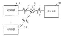
図1は、本発明にかかる通信システムのシステム構成を示す図である。通信システムは、送信装置1と受信装置2が交換機3を有する電話回線4にて接続している。
【0023】
図2は、送信装置1のブロック図を示す。送信装置1は、交換機3の出力するリングバックトーンを検出するリングバックトーン検出手段11と、電話回線4の閉成/開放を行う回線閉成/開放手段12と、リングバックトーン検出手段11からの出力により回線閉成/開放手段12を制御する回線制御手段13を有して構成する。
【0024】
図3は、受信装置2のブロック図である。受信装置2は、登録されている送信装置1が接続されている電話回線の加入者回線番号及び後述する時刻を対応して記憶する記憶手段21と、交換機3より送出される送信装置1の加入者回線番号等を受信する受信手段22と、電話回線4の閉成または開放を行う回線閉成/開放手段23と、電話回線4に接続され交換機3の送出する起動信号を受信する起動信号受信手段24と、受信手段22または起動信号受信手段24からの出力により回線閉成/開放手段23を制御する回線制御手段25を有して構成している。
【0025】
記憶手段21は、予め送信装置1の接続されている加入者回線番号と加入者回線番号に関連させて該加入者回線番号を最近受信した時刻を記憶しているメモリ211と、加入者回線番号を受信手段22から受信すると計時手段213が入力する現時刻を該加入者回線番号に対応してメモリ211に記憶させる記憶制御手段212にて構成している。
【0026】
次に、このように構成された通信システムの動作について、図4をもとに説明する。先ず、送信装置1が送信のために電話回線4を閉成すると、交換機3から送信装置1にダイヤルトーンが戻される。そして、送信装置1は、受信装置2の電話番号(選択信号)を交換機3に送出する(ステップ1)。
【0027】
次に、交換機3は、受信装置2に対して起動信号を送出する。受信装置2では、この起動信号を起動信号受信手段24にて受信すると、回線制御手段25から回線閉成/開放手段23を動作させ、電話回線4を閉成する。次に交換機3は、電話回線4を介して送信装置1の接続されている電話回線の加入者回線番号を送出する。そして、受信装置は、交換機3から送信される該送信装置1の加入者回線番号を受信手段22にて受信する。受信が完了すると、受信手段22から回線制御手段25に出力され、回線制御手段25から回線閉成/開放手段23にて電話回線4を開放する。また、記憶制御手段212では、計時手段213の計時している現在時刻を、メモリ211に記憶している加入者回線番号と関連づけて記憶する。(ステップ2)
交換機3は、受信装置2の回線開放を認識すると、送信装置1に対してリングバックトーンを、受信装置2に対して呼出信号をそれぞれ送信する。送信装置1は、該リングバックトーンをリングバックトーン検出手段11にて検出すると、回線制御手段13から回線閉成/開放手段12を制御し、電話回線を開放する。
【0028】
一方、受信装置2では、呼出信号を受信しても、所定回数以上の呼出信号を受信するまで、電話回線を閉成させないようにしている。(ステップ3)
したがって、受信装置2では、送信装置1との回線が接続される前に、送信装置1から送信動作があったことを認識できるのである。これによって、電話回線4を占有する時間が極めて短くて済むので、通信効率のよい通信システムが提供できる。また、送信装置1と受信装置2とを接続することなく、受信装置2にて送信装置1及び電話回線4の正常を確認できるので、電話回線の接続料金が必要でなく、頻繁に送信装置1の状態確認が必要な機械警備システムや非常通報システムなどでは、システムの信頼性を安価に向上させることが可能になる。
【0029】
【実施例】
次に、図5から図12を参照して、本発明を機械警備システムに適用した場合の第1の実施例を説明する。
【0030】
図5は、機械警備システムのシステム構成を示す図である。
【0031】
同図に示すように、機械警備システムは、複数の警備対象である建物に通報装置5がそれぞれ設置され、センタ装置6と電話回線4を介して接続している。センタ装置6は、交換機3と2本の電話回線4a、4bにて接続されている。そして、4aは通報装置5から異常通報を受信するための電話回線であり、4bは定期通報を受信するための電話回線である。
【0032】
図6は、通報装置5のブロック図を示す。通報装置5は、図示しない監視対象(以下、物件という。)の適所に設置される火災センサー・侵入センサー等の各種センサーからの信号を受けるセンサ入力部51、機械警備のセット/解除操作、現状態の表示、各種設定等を行う液晶タッチパネルを用いた操作表示部52、定期通報の間隔を計時するタイマー53、電話回線4を介してセンタ装置6と通信を行う通信部55、通報装置5を動作させるプログラムや各種データを記憶する記憶部56及びこれらを制御する制御部54にて構成されている。
【0033】
図示していないが、通信部55には電話回線4と交換機3との直流ループの閉成/開放を行うリレー、交換機3からのリングバックトーンを検出する手段が少なくとも設けられている。また、記憶部56には、図8に示すように物件固有の識別コードである物件コード、センサが異常を検出したとき等に通報を行う為の異常通報用電話番号、定期通報するときの為の電話番号である定期通報用電話番号などを記憶している。
【0034】
このように構成された通報装置5の通報動作を図11のフローを参照して説明する。
【0035】
先ず、通報装置5が物件に設置され電源の投入により、タイマー53が計時を開始する(S101)。本実施例では、タイマー53は15分でタイムアップするものである。なお、タイマー53の計時する時間は、短いほど定期通報の時間間隔が短くなりセキュリティ性が向上する反面、あまり短いと定期通報だけのために電話回線4の占有時間が長くなることを考慮して適宜の時間が選択される。
【0036】
そして、S102にて、センサからの異常信号の入力や操作表示部52からの警備セット操作の入力などがあるか否かを監視している。ここで、火災センサから火災検知信号の入力があると、S109に進み通報動作をする。S109では、通信部55にて電話回線4と直流ループを閉成する。そして、記憶部56に記憶されている異常通報用電話番号をダイヤリングする。そして、センタ装置6からの応答信号の受信を待つ(S111)。なお、同図のフローに記載していないが、応答信号が所定時間経過しても受信できない場合や電話回線4がビジー状態であれば一旦直流ループを開放し、S109からの送信動作を繰り返す。
【0037】
センタ装置6から応答信号を受信すれば、S112にて火災異常信号、物件コード等をセンタ装置6に送出するなどの通信を行う(S112)。
【0038】
その後、電話回線4の直流ループを開放し(S107)、タイマー53をリセット(S108)の上、S101に戻る。
【0039】
一方、S102にて状態変化がない場合、S103に進む。S103では、タイマー53がタイムアップしたか否か判断している。タイムアップしていない場合は、S102に戻り、物件の状態変化の監視を続ける。タイマー53がタイムアップすると、通信部55にて電話回線4の直流ループを閉成する。そして、記憶部56から定期通報用電話番号を読みだし、ダイヤリングする(S105)。
【0040】
そして、交換機3からリングバックトーンの受信を検出する(S106)と、直ちに電話回線4の直流ループを開放する(S107)。そして、タイマー53をリセット(S108)し、S101に戻る。
【0041】
次に、センタ装置6について説明する。図7は、センタ装置6のブロック図である。センタ装置6は、通報装置5の異常通報信号を受信用の電話回線4aと接続する異常通報用通信部61、通報装置5の定期通報を受信用の電話回線4bと接続する定期通報用通信部62、現在時刻を計時する計時部64、センタ装置6を動作させるプログラムや各種データ等を記憶する記憶部65、物件の現状態や定期異常の発生等を表示するディスプレイである表示部66、管制員が異常を確認した場合等に操作する操作部67、これらのセンタ装置を制御する制御部63にて構成している。
【0042】
ここで、センタ装置6が、異常通報受信用の電話回線4a、定期通報受信用の電話回線4bを有している理由について述べる。
【0043】
機械警備システムの場合、1台のセンタ装置6に対し、多数の通報装置5が電話回線4を介して接続される。そして、センタ装置6は、交換機3と接続している加入者回線を介してのみ、通報装置5からの通報を受信できるので、この加入者回線の空き状態によって、通報装置5からセンタ装置6への信号伝達に要する時間が決まる。このため、緊急性の高い火災信号や侵入者検出信号等の異常通報と、比較的緊急性の低いが通報回数が多い定期通報とを同じ加入者回線にて受信すると、緊急性の高い異常通報のセンタ装置への到達が定期通報によって邪魔され遅れることが起こり得る。
【0044】
そこで、本実施例では、センタ装置6に異常通報受信用の電話回線4aと定期通報受信用電話回線4bを接続している。
【0045】
なお、図9に示すように、記憶部65は、各顧客毎に物件コード、通報装置の電話番号、定期受信時刻、現状態などを記憶している。
【0046】
図12は、センタ装置6の受信動作を示すフローである。
【0047】
センタ装置6は、情報受信端末起動信号が交換機3から異常通報用通信部61又は定期通報用通信部62にて受信するのを監視している(S201)。そして、S201にて、情報受信端末起動信号を受信すると、該受信した電話回線4a又は4bの直流ループを閉成する(S202)。そして、交換機3より送出される通報装置5が接続されている電話回線の加入者回線番号(以下、通報装置の電話番号という。)を受信し(S203)、その後、該電話回線の直流ループを開放する(S204)。そして、S205にて、定期通報用の電話回線4bからの情報受信端末起動信号であったならば、S206に進む。S206では、記憶部65の定期受信時刻を計時部64からの入力される現在の時刻に更新記憶し(S206)、S201に戻る。なお。図示していないが、この定期受信時刻から所定時間経過した場合は、定期通報の未受信を表示部66に表示する。この表示を管制員がみると、該当する物件に対処者を急行させ、物件の安全等の維持を図る。
【0048】
S205にて、電話回線4aからの情報受信端末起動信号であったならば、S207に進む。S207では、その後に交換機3から所定時間内に所定回数の呼出信号を受信するか否か監視している。そして、所定時間内に所定回数の呼出信号を受信しなければ(S212)、S201に戻る。一方、呼出信号を受信すると、電話回線4aの直流ループを閉成し(S208)、通報装置5からの状態信号等を受信する(S209)。そして、表示部66の表示を変えるとともに、記憶部65の記憶内容を更新記憶し(S210)、電話回線4aの直流ループを開放(S211)の上、S206に進む。また、ここで、異常信号を受信した場合は、目だつように表示部66に異常表示をさせるのが好ましい。そして、異常表示を管制員がみて、対処者を該物件に急行させる等適切に処理される。なお、本フローには記載していないが、センタ装置6が、間違い電話等により呼出信号を受信した場合、通報装置5の信号伝送の場合と異なり、現状態等の信号を受信できず、そのまま直流ループを開放する。
【0049】
次に、以上に説明してきた構成の機械警備システムの動作を、図10をもとに説明する。
【0050】
先ず、通報装置5が定期送信のために電話回線4を閉成すると、交換機3から通報装置5にダイヤルトーンが戻される。そして、通報装置5は、センタ装置6の定期通報用の電話番号(選択信号)を交換機3に送出する。
【0051】
次に、交換機3は、センタ装置6に接続されている定期通報用の電話回線4bに対して情報受信端末起動信号を送出する。センタ装置6の定期通報用通信部62では、この情報受信端末起動信号を受信すると、回線閉成/開放手段を動作させ、電話回線4bの直流ループを閉成する。そして、交換機3から送信される該通報装置5の電話番号を定期通報用通信部62にて受信する。受信が完了すると、定期通報用受信部62にて電話回線4bの直流ループを開放する。このときに、前述したように、記憶部65に定期受信時刻を通報装置5の電話番号に関連づけて記憶するとともに、表示部66の表示を変える。
【0052】
一方、交換機3は、センタ装置6の定期通報用電話回線4bの直流ループの開放を認識すると、通報装置5に対してリングバックトーンを送出する。通報装置5は、該リングバックトーンを通信部55にて検出すると、電話回線4の直流ループを開放する。
【0053】
なお、センタ装置6では、呼出信号を受信しても、所定回数以上の呼出信号を受信するまで、電話回線を閉成させないようにしている。
【0054】
したがって、センタ装置6では、通報装置5とセンタ装置6とが接続される前に、通報装置5から通報動作があったことを認識できるのである。これによって、電話回線4を占有する時間が極めて短くて済むので、通信効率のよい通信システムが提供できる。また、通報装置5とセンタ装置6との回線を接続することなく、センタ装置6にて通報装置5及び電話回線4の正常を確認できるので、電話回線の接続料金が必要でなく、頻繁に通報装置5の状態確認が必要な機械警備システムや非常通報システムなどでは、システムの信頼性を安価に向上させることが可能になる。更に、異常通報受信用の電話回線4aと定期通報受信用の電話回線4bにて、異常通報と定期通報とを区別して受信することにより、異常通報と定期通報の識別が可能になる。そして、機械警備システムにおける緊急度の低い通報(例えば、定期通報)が、緊急度の高い通報(例えば、火災信号や侵入者検出信号の通報)をセンタ装置6に送信することを妨害しない。これによって、機械警備システムのセキュリティ性が向上するのである。
【0055】
次に、第2の実施例について、図13〜図15を参照して説明する。
【0056】
図13は、第2の実施例にかかる機械警備システムのシステム構成を示す図である。
【0057】
同図に示すように、機械警備システムは、複数の警備対象である建物に通報装置7がそれぞれ設置され、センタ装置8と電話回線4を介して接続されている。センタ装置8は、交換機3と1本の電話回線4cにて接続されている。ここで、1本の電話回線とは、物理的に1本の電話回線を指すのではなく、異常通報用の電話回線と定期通報用の電話回線とを区別せずに同一の電話回線で受信することを意味する。つまり、第1の実施例の場合は、異常通報受信用の電話回線4aと定期通報用の電話回線4bとに通報の種別によって区別して受信できるようにしていたのを、異常通報と定期通報とを混在して電話回線4cにて受信するようにしたものである。
【0058】
第1の実施例の通報装置5と本実施例の通報装置7とは、通報装置5が通報先電話番号を2箇所記憶しているのに対し、通報装置7は通報先電話番号を1箇所記憶し、異常通報と定期通報の通報先を同じにしている点が異なる。
【0059】
また、第1の実施例のセンタ装置6と本実施例のセンタ装置8とは、センタ装置6が異常通報用通信部と定期通報用通信部を有し、2本の電話回線にそれぞれ個別に接続しているのに対し、センタ装置8で1本の電話回線4cに1つの通信部を有している点と、後述する受信信号の処理動作が異なる。その他の点については、第1の実施例と基本的に同じであるので説明を省略する。
【0060】
図15を参照して、センタ装置8の動作について説明する。
【0061】
センタ装置8は、情報受信端末起動信号を交換機3から受信するまで待機している(S301)。そして、S301にて、情報受信端末起動信号を受信すると、該受信した電話回線4cの直流ループを閉成する(S302)。そして、交換機3を介して送出される当該通報装置7の加入者回線番号(以下、通報装置の電話番号という。)を受信し(S303)、その後、電話回線4cの直流ループを開放する(S304)。そして、S305にて、交換機3から送出される呼出信号の数をカウントし、所定回数例えば3回をカウントするとS307に進む。一方、所定時間内に呼出信号を3回カウントしなければ、S306に進み定期受信時刻を更新しS301に戻る。なお、通報装置7は、リングバックトーンを検出すると、電話回線4の直流ループを開放するので、交換機3から呼出信号が何回も送出されることはない。このため、前記所定回数は、通報装置7がリングバックトーンを受信した後に、直流ループを開放するまでに交換機3から送出される呼出信号の数より多い数に適宜設定される。
【0062】
S307では、電話回線4cの直流ループを閉成し、通報装置7からの状態信号等を受信する(S308)。そして、表示部の表示を変えるとともに、記憶部の記憶内容を更新記憶し(S309)、電話回線4cの直流ループを開放(S310)の上、S306に進む。
【0063】
図14を参照して、第2の実施例の機械警備システムの動作について説明する。
【0064】
先ず、通報装置7が異常通報のために電話回線4を閉成すると、交換機3から通報装置7にダイヤルトーンが戻される。そして、通報装置7は、センタ装置8にセンタ装置8の電話番号(選択信号)を交換機3に送出する。
【0065】
次に、交換機3は、センタ装置8に接続されている電話回線4cに対して情報受信端末起動信号を送出する。センタ装置8は、電話回線4cの直流ループを閉成する。そして、交換機3から送信される該通報装置7の電話番号を受信する。受信が完了すると、電話回線4cの直流ループを開放する。交換機3は、センタ装置8の電話回線4cの直流ループの開放を認識すると、電話回線4cを介し通報装置7に対してリングバックトーンを送出する。通報装置7は、該リングバックトーンを受信しても、異常通報のときは直流ループを開放せず、センタ装置8からの応答信号を待つ。そして、センタ装置8にて交換機3から送出される呼出信号が所定回数(本実施例では、3回)受信すると、電話回線4cの直流ループを閉成する。以上により、通報装置7とセンタ装置8とが電話回線4にて接続されたこととなる。そして、センタ装置8が図示しない応答信号を通報装置7に送出する。通報装置7は該応答信号を受信すると、センタ装置8に異常信号、物件状態等の送出を開始する。その後、通信が終了すると、通報装置7及びセンタ装置8はそれぞれ電話回線4の直流ループを開放し、通報動作を終了させる。
【0066】
また、定期通報の場合は、同図のAにて、通報装置7がリングバックトーンを受信すると、電話回線4の直流ループを開放するので、交換機3からセンタ装置8に呼出信号が3回送出されない。このため、センタ装置8にて電話回線4cの直流ループを再度閉成せず、定期受信時刻を更新する処理を行い定期通報処理を終了する。
【0067】
これによって、センタ装置8を1本の電話回線とした場合であっても、異常通報と定期通報を区別して処理が行える。
【0068】
本実施例では、定期通報と異常通報とを呼出信号の受信回数にて区別したが、異常通報の場合は、通報装置7からダイヤリングする際に加入者回線番号の通知を拒否するコード(例えば、センタ装置8の電話番号の先頭に「184」)を付加させ、定期通報の場合は付加させないようにし、異常通報と定時通報とをセンタ装置8にて区別することもできる。
【0069】
この場合は、センタ装置8の処理は、図15におけるS305を変更すれば実現できる。すなわち、S303にて、交換機3から電話回線4cを介してセンタ装置8に送出された信号に通報装置7の電話番号が含まれていると、S305にて定期通報と判断する。一方、通報装置7の電話番号が含まれていないと、異常通報と判断するようにする。そして、定期通報を判断すれば、S306の処理を行い、異常通報と判断すれば、S307の処理に移行する。
【0070】
この方式であれば、第2の実施例の場合に比べ、呼出信号をカウントする時間分だけ短縮され、異常信号がセンタ装置に早く到達できる。
【図面の簡単な説明】
【図1】本発明にかかる通信システムのシステム構成図
【図2】本発明にかかる送信装置のブロック図
【図3】本発明にかかる受信装置にブロック図
【図4】本発明にかかる通信システムの動作フロー
【図5】第1の実施例の機械警備システムのシステム構成図
【図6】第1の実施例の通報装置のブロック図
【図7】第1の実施例のセンタ装置のブロック図
【図8】第1の実施例にかかる通報装置の記憶部の記憶データ
【図9】第1の実施例にかかるセンタ装置の記憶部の記憶データ
【図10】第1の実施例の機械警備システムの動作フロー
【図11】第1の実施例にかかる通報装置の処理フロー
【図12】第1の実施例にかかるセンタ装置の処理フロー
【図13】第2の実施例の機械警備システムのシステム構成図
【図14】第2の実施例の機械警備システムの動作フロー
【図15】第2の実施例にかかるセンタ装置の処理フロー
【符号の説明】
1・・・・送信装置
11・・・リングバックトーン検出手段
12・・・回線閉成/開放手段
13・・・回線制御手段
2・・・・受信装置
21・・・記憶手段
211・・メモリ
212・・記憶制御手段
213・・計時手段
22・・・受信手段
23・・・回線閉成/開放手段
24・・・起動信号受信手段
25・・・回線制御手段
3・・・・交換機
4・・・・電話回線
4a・・・異常通報受信用の電話回線
4b・・・定期通報受信用の電話回線
4c・・・電話回線
5,7・・通報装置
51・・・センサ入力部
52・・・操作表示部
53・・・タイマー
54・・・制御部
55・・・通信部
56・・・記憶部
6,8・・センタ装置
61・・・異常通報用通信部
62・・・定期通報用通信部
63・・・制御部
64・・・計時部
65・・・記憶部
66・・・表示部
67・・・操作部 [0001]
BACKGROUND OF THE INVENTION
The present invention relates to a communication system using a telephone line, and more particularly to a communication system capable of notifying a receiving apparatus of a subscriber line number of a transmitting apparatus.
[0002]
[Prior art]
Conventionally, various communication systems using telephone lines have been put into practical use, such as an elevator remote monitoring system, a machine security system, and an emergency call system.
[0003]
Here, the conventional technology will be described by taking a machine security system as an example.
[0004]
In the machine security system, a reporting device is installed in a building to be guarded, and is connected to a center device via a telephone line.
[0005]
An intrusion sensor or a fire sensor installed at an appropriate place in the building is connected to the notification device.
[0006]
For example, when a fire sensor detects a fire, a fire signal is notified from the notification device to the center device via a telephone line. When the center apparatus receives the fire signal, it takes appropriate measures such as directing a coping person to the monitoring target.
[0007]
In addition, when a reporting device malfunctions or a telephone line is disconnected, even if the sensor detects a fire or the like, a signal is not transmitted to the center device, and the machine security system does not function.
[0008]
Therefore, even if a sensor or the like has not detected an abnormality, the reporting device periodically reports to the center device via the telephone line, and the reporting device and the telephone line are normal depending on the presence or absence of this periodic notification. Was monitored by the center device.
[0009]
[Problems to be solved by the invention]
Periodic reporting differs from reporting status change information in a monitoring target such as a fire signal, and the content of the reporting itself has no significant meaning.
[0010]
In addition, when the time interval of the regular notification is set to be long, trouble such as disconnection of the telephone line is slow to be transmitted to the center device. On the other hand, if the setting is short, troubles will be transmitted more quickly, but as the number of notifications increases, the telephone line connection fee will increase, and the running cost of the mechanical security system will increase, hindering the spread of the security system. Become. That is, although the contents of the report itself are not important, a telephone line connection fee increases in order to improve security. In addition, when a large number of transmission devices are connected to the reception device, the telephone line connected to the reception device is congested if the time interval of the periodic notification of the transmission device is short. As a result, there is a problem that transmission of important state change information (for example, a fire signal or an intruder detection signal) to the receiving device is delayed.
[0011]
Therefore, an object of the present invention is to provide a communication system in which the communication time of the telephone line is reduced as much as possible and the communication efficiency is improved in the case of a report having no meaning in the report content itself.
[0012]
[Means for Solving the Problems]
According to a first aspect of the present invention, there is provided a transmitter having communication means for releasing a line when a ringback tone is detected from an exchange, an activation signal receiving means for receiving an activation signal from the exchange, and a line closing for closing and releasing a telephone line. A subscriber of the transmitting apparatus includes a generating / opening means, a receiving means for receiving a subscriber line number of the transmitting apparatus from the exchange, and a line control means for closing the line when receiving an activation signal. Provided is a communication system using a telephone line connected to an exchange capable of notifying a line number to the receiving apparatus.
[0013]
Then, when making a report whose transmission content itself is meaningless (for example, a regular report), first, the transmission device dials and sends a selection signal to the exchange. When the exchange receives this selection signal, the exchange sends an activation signal to the selected receiver. When the receiving device receives the activation signal, the receiving device closes the telephone line. When the telephone line is closed, the exchange sends the subscriber line number to which the transmitting apparatus is connected to the receiving apparatus. When the subscriber line number is received, the receiving apparatus opens the telephone line. When the exchange recognizes the opening of the telephone line, it sends a ringback tone to the transmitting device via the telephone line. When the transmitting device detects the ringback tone, it opens the telephone line and terminates communication.
[0014]
Thereby, the receiving apparatus can know that there was a report from the transmitting apparatus before the line between the transmitting apparatus and the receiving apparatus is connected. Therefore, it is possible to shorten the time required to occupy the telephone line for a report having no meaning in the transmission content itself. In addition, since the receiving device can know the transmission operation of the transmitting device without being charged for the usage fee of the telephone line, the running cost of the communication system can be reduced.
[0015]
A second invention is a transmission device used in a communication system using a telephone line for notifying a subscriber line number of a transmission device to a reception device, and includes a communication means for releasing a line when a ringback tone is detected from an exchange. Provided is a transmission apparatus.
[0016]
As a result, the time for occupying the subscriber line between the transmitter and the exchange is shortened.
[0017]
According to a third aspect of the present invention, there is provided a receiving apparatus for use in a communication system using a telephone line for notifying a receiving apparatus of a subscriber line number of a transmitting apparatus, an activation signal receiving means for receiving an activation signal from an exchange, and the exchange Receiving means for receiving the subscriber line number of the transmitting device, line closing / opening means for closing and opening the telephone line, and line control means for closing the line when receiving an activation signal and then opening it And a storage device for storing the subscriber line number of the transmitter and the time when the notification of the subscriber line number is received.
[0018]
As a result, the receiving device can receive the subscriber line number of the telephone line to which the transmitting device that performed the transmission operation from the exchange is connected, and can store the received time, so it is possible to check when the notification of the transmitting device has occurred. It can be done.
[0019]
In the fourth invention, in addition to the first invention or the second invention, the transmission device stores a plurality of transmission destination telephone numbers, and the communication system or transmission can select the transmission destination telephone numbers according to the transmission contents. Providing the device.
[0020]
This makes it possible to perform a transmission operation on a dedicated receiving apparatus only in the case of a report that does not make sense for the transmission content itself, and can prevent the transmission content itself from affecting a meaningful report.
[0021]
DETAILED DESCRIPTION OF THE INVENTION
An embodiment of the invention will be described with reference to FIGS.
[0022]
FIG. 1 is a diagram showing a system configuration of a communication system according to the present invention. In the communication system, a
[0023]
FIG. 2 shows a block diagram of the
[0024]
FIG. 3 is a block diagram of the receiving
[0025]
The
[0026]
Next, the operation of the communication system configured as described above will be described with reference to FIG. First, when the
[0027]
Next, the
When the
[0028]
On the other hand, even if the receiving
Accordingly, the receiving
[0029]
【Example】
Next, a first embodiment in the case where the present invention is applied to a machine security system will be described with reference to FIGS.
[0030]
FIG. 5 is a diagram showing a system configuration of the machine security system.
[0031]
As shown in the figure, in the mechanical security system, a
[0032]
FIG. 6 shows a block diagram of the
[0033]
Although not shown, the communication unit 55 is provided with at least a relay for closing / opening a DC loop between the
[0034]
The notification operation of the
[0035]
First, when the
[0036]
In S102, it is monitored whether there is an input of an abnormal signal from the sensor or an input of a guard set operation from the operation display unit 52. Here, if a fire detection signal is input from the fire sensor, the process proceeds to S109 to perform a notification operation. In S109, the communication line 55 closes the
[0037]
If a response signal is received from the
[0038]
Thereafter, the DC loop of the
[0039]
On the other hand, when there is no state change in S102, the process proceeds to S103. In S103, it is determined whether or not the timer 53 has expired. If the time has not expired, the process returns to S102 and continues to monitor the property state change. When the timer 53 expires, the communication unit 55 closes the DC loop of the
[0040]
When the reception of the ring back tone from the
[0041]
Next, the
[0042]
Here, the reason why the
[0043]
In the case of a machine security system, a large number of
[0044]
Therefore, in this embodiment, the
[0045]
As shown in FIG. 9, the storage unit 65 stores the property code, the telephone number of the reporting device, the periodic reception time, the current state, etc. for each customer.
[0046]
FIG. 12 is a flowchart showing the reception operation of the
[0047]
The
[0048]
If it is an information reception terminal activation signal from the telephone line 4a in S205, the process proceeds to S207. In S207, it is monitored whether or not a call signal is received a predetermined number of times within a predetermined time from the
[0049]
Next, the operation of the mechanical security system configured as described above will be described with reference to FIG.
[0050]
First, when the
[0051]
Next, the
[0052]
On the other hand, when the
[0053]
In the
[0054]
Accordingly, the
[0055]
Next, a second embodiment will be described with reference to FIGS.
[0056]
FIG. 13 is a diagram illustrating a system configuration of the machine security system according to the second embodiment.
[0057]
As shown in the figure, in the mechanical security system, a reporting device 7 is installed in each of a plurality of buildings to be guarded, and is connected to a center device 8 via a
[0058]
In the
[0059]
Further, the
[0060]
The operation of the center device 8 will be described with reference to FIG.
[0061]
The center device 8 stands by until an information reception terminal activation signal is received from the exchange 3 (S301). When the information receiving terminal activation signal is received in S301, the DC loop of the received telephone line 4c is closed (S302). Then, the subscriber line number of the notification device 7 (hereinafter referred to as the telephone number of the notification device) sent through the
[0062]
In S307, the DC loop of the telephone line 4c is closed, and a status signal or the like from the notification device 7 is received (S308). And while changing the display of a display part, the memory content of a memory | storage part is updated and memorize | stored (S309), the direct current | flow loop of the telephone line 4c is open | released (S310), and it progresses to S306.
[0063]
With reference to FIG. 14, the operation of the machine security system of the second embodiment will be described.
[0064]
First, when the reporting device 7 closes the
[0065]
Next, the
[0066]
Also, in the case of periodic notifications, when the notification device 7 receives the ringback tone in A in the figure, the DC loop of the
[0067]
As a result, even when the center device 8 is a single telephone line, it is possible to perform processing by distinguishing between an abnormal report and a regular report.
[0068]
In the present embodiment, periodic notification and abnormality notification are distinguished by the number of receptions of the call signal. However, in the case of abnormality notification, a code that rejects notification of the subscriber line number when dialing from the notification device 7 (for example, In addition, “184”) is added to the head of the telephone number of the center device 8 so that it is not added in the case of periodic notification, and the abnormality notification and the regular notification can be distinguished by the center device 8.
[0069]
In this case, the processing of the center device 8 can be realized by changing S305 in FIG. That is, if the telephone number of the reporting device 7 is included in the signal sent from the
[0070]
With this method, compared with the case of the second embodiment, it is shortened by the time for counting the calling signal, and the abnormal signal can reach the center device earlier.
[Brief description of the drawings]
FIG. 1 is a system configuration diagram of a communication system according to the present invention.
FIG. 2 is a block diagram of a transmission apparatus according to the present invention.
FIG. 3 is a block diagram of a receiving apparatus according to the present invention.
FIG. 4 is an operation flow of a communication system according to the present invention.
FIG. 5 is a system configuration diagram of the machine security system according to the first embodiment.
FIG. 6 is a block diagram of a notification device according to the first embodiment.
FIG. 7 is a block diagram of the center device according to the first embodiment.
FIG. 8 shows data stored in the storage unit of the reporting device according to the first embodiment.
FIG. 9 shows data stored in the storage unit of the center device according to the first embodiment;
FIG. 10 is an operation flow of the machine security system according to the first embodiment.
FIG. 11 is a processing flow of the reporting device according to the first embodiment.
FIG. 12 is a processing flow of the center device according to the first embodiment;
FIG. 13 is a system configuration diagram of a machine security system according to a second embodiment.
FIG. 14 is an operation flow of the machine security system according to the second embodiment.
FIG. 15 is a processing flow of the center device according to the second embodiment;
[Explanation of symbols]
1 ... Transmitter
11 Ring ring tone detection means
12 ... Line closing / opening means
13: Line control means
2 ... Receiver
21 ... Storage means
211 .. Memory
212..Storage control means
213 Timekeeping means
22 ... Receiving means
23: Circuit closing / opening means
24. Activation signal receiving means
25 ... Line control means
3 ... Switch
4 ... Telephone line
4a ... Telephone line for receiving error reports
4b: Telephone line for receiving periodic reports
4c ... telephone line
5,7 ... Notification device
51 ... Sensor input part
52 ... Operation display section
53 ... Timer
54 ... Control unit
55 ... Communication Department
56... Storage unit
6,8 ・ ・ Center equipment
61 ・ ・ ・ Communication section for error reporting
62 ... Communication department for periodic reports
63 ... Control unit
64 ... Timekeeping section
65: Storage unit
66 ... Display section
67 .. operation unit
Claims (3)
前記送信装置は、
前記電話回線の閉成及び開放を行う回線閉成/開放手段と、
交換機の出力するリングバックトーンを検出するリングバックトーン検出手段と、
回線を閉成し交換機からダイヤルトーンが戻されると前記受信装置の電話番号を交換機に送出し、前記交換機から送出されたリングバックトーンを検出すると回線を開放する通信手段と
を有し、
前記受信装置は、
交換機から起動信号を受信する起動信号受信手段と、
前記電話回線の閉成及び開放を行う回線閉成/開放手段と、
前記交換機から前記送信装置の加入者回線番号を受信する受信手段と、
前記起動信号を受信すると回線を閉成し、前記加入者回線番号の受信を完了すると回線を開放して、前記送信装置に対するリングバックトーンを前記交換機に送出させる回線制御手段と
を有することを特徴とした通信システム。In a communication system using a telephone line for notifying the receiver of the subscriber line number of the transmitter,
The transmitter is
Line closing / opening means for closing and opening the telephone line;
A ringback tone detecting means for detecting a ringback tone output from the exchange;
A communication means for closing the line and sending the telephone number of the receiving device to the exchange when the dial tone is returned from the exchange , and opening the line when the ringback tone sent from the exchange is detected;
The receiving device is:
An activation signal receiving means for receiving an activation signal from the exchange;
Line closing / opening means for closing and opening the telephone line;
Receiving means for receiving a subscriber line number of the transmitting device from the exchange;
It closes the line when receiving the activation signal, and opens the line Upon completion of reception of the subscriber line number, that it has a line control means for Ru ringback tone is sent to the exchange to said transmitting device A featured communication system.
交換機から起動信号を受信する起動信号受信手段と、An activation signal receiving means for receiving an activation signal from the exchange;
前記電話回線の閉成及び開放を行う回線閉成/開放手段と、Line closing / opening means for closing and opening the telephone line;
前記交換機から前記送信装置の加入者回線番号を受信する受信手段と、Receiving means for receiving a subscriber line number of the transmitting device from the exchange;
前記起動信号を受信すると回線を閉成し、前記加入者回線番号の受信を完了すると回線を開放して、前記送信装置に対するリングバックトーンを前記交換機に送出させる回線制御手段と、A line control means for closing the line when receiving the activation signal, opening the line when reception of the subscriber line number is completed, and causing the exchange to send a ringback tone to the transmitter;
前記送信装置の加入者回線番号及び加入者回線番号通知を受信した時刻を記憶する記憶手段とStorage means for storing the subscriber line number of the transmitter and the time when the subscriber line number notification is received;
を有した受信装置。A receiving apparatus.
Priority Applications (1)
| Application Number | Priority Date | Filing Date | Title |
|---|---|---|---|
| JP05426297A JP3857375B2 (en) | 1997-02-24 | 1997-02-24 | COMMUNICATION SYSTEM AND RECEPTION DEVICE USED FOR COMMUNICATION SYSTEM |
Applications Claiming Priority (1)
| Application Number | Priority Date | Filing Date | Title |
|---|---|---|---|
| JP05426297A JP3857375B2 (en) | 1997-02-24 | 1997-02-24 | COMMUNICATION SYSTEM AND RECEPTION DEVICE USED FOR COMMUNICATION SYSTEM |
Publications (2)
| Publication Number | Publication Date |
|---|---|
| JPH10243122A JPH10243122A (en) | 1998-09-11 |
| JP3857375B2 true JP3857375B2 (en) | 2006-12-13 |
Family
ID=12965660
Family Applications (1)
| Application Number | Title | Priority Date | Filing Date |
|---|---|---|---|
| JP05426297A Expired - Fee Related JP3857375B2 (en) | 1997-02-24 | 1997-02-24 | COMMUNICATION SYSTEM AND RECEPTION DEVICE USED FOR COMMUNICATION SYSTEM |
Country Status (1)
| Country | Link |
|---|---|
| JP (1) | JP3857375B2 (en) |
Families Citing this family (5)
| Publication number | Priority date | Publication date | Assignee | Title |
|---|---|---|---|---|
| US7158625B2 (en) * | 2002-06-17 | 2007-01-02 | Qualcomm Incorporated | Method and apparatus for automatically terminating a call |
| JP4611759B2 (en) * | 2005-01-19 | 2011-01-12 | 矢崎総業株式会社 | Alarm |
| JP2006279875A (en) * | 2005-03-30 | 2006-10-12 | Sogo Keibi Hosho Co Ltd | Security system |
| JP4561492B2 (en) * | 2005-06-23 | 2010-10-13 | コニカミノルタビジネステクノロジーズ株式会社 | Remote diagnosis apparatus, remote diagnosis system, and information collection program |
| JP2010171786A (en) * | 2009-01-23 | 2010-08-05 | Yamatake Corp | Failure determination system |
-
1997
- 1997-02-24 JP JP05426297A patent/JP3857375B2/en not_active Expired - Fee Related
Also Published As
| Publication number | Publication date |
|---|---|
| JPH10243122A (en) | 1998-09-11 |
Similar Documents
| Publication | Publication Date | Title |
|---|---|---|
| US4652859A (en) | Alarm reporting system | |
| EP0382544A2 (en) | Alarm system utilizing wireless communication path | |
| CA2605019C (en) | A system and method for capturing and rerouting an individual local security system | |
| JP3857375B2 (en) | COMMUNICATION SYSTEM AND RECEPTION DEVICE USED FOR COMMUNICATION SYSTEM | |
| US8854187B2 (en) | System and method for wireless interactive security services using a key-switch interface | |
| JP2825237B2 (en) | Automatic reporting equipment | |
| JP3118591B2 (en) | Emergency notification system using telephone line | |
| JP4280912B2 (en) | Monitoring and reporting system | |
| JP3004156B2 (en) | Automatic information transmission device | |
| KR200306169Y1 (en) | Automatic information apparatus of mechanical trouble | |
| JP3834150B2 (en) | Transfer telephone equipment | |
| JP3327730B2 (en) | Remote monitoring system | |
| JPH0158557B2 (en) | ||
| JP2958860B2 (en) | Alarm transmission device | |
| JP3009313B2 (en) | Information transmission device | |
| JP2546988Y2 (en) | Mechanical security equipment | |
| JPH054363Y2 (en) | ||
| JPS63182950A (en) | Monitoring device | |
| JPH07123165A (en) | Monitor controller | |
| JP3597063B2 (en) | Security terminal device and monitoring device for security monitoring system | |
| JPH044652A (en) | Home controller | |
| KR970000460B1 (en) | Automatic calling apparatus of existence of person | |
| JPH0218632Y2 (en) | ||
| JPH0324852A (en) | Communication equipment | |
| JPH11316887A (en) | Message device |
Legal Events
| Date | Code | Title | Description |
|---|---|---|---|
| A521 | Written amendment |
Free format text: JAPANESE INTERMEDIATE CODE: A523 Effective date: 20040219 |
|
| A621 | Written request for application examination |
Free format text: JAPANESE INTERMEDIATE CODE: A621 Effective date: 20040219 |
|
| A977 | Report on retrieval |
Free format text: JAPANESE INTERMEDIATE CODE: A971007 Effective date: 20060127 |
|
| A131 | Notification of reasons for refusal |
Free format text: JAPANESE INTERMEDIATE CODE: A131 Effective date: 20060131 |
|
| A521 | Written amendment |
Free format text: JAPANESE INTERMEDIATE CODE: A523 Effective date: 20060331 |
|
| TRDD | Decision of grant or rejection written | ||
| A01 | Written decision to grant a patent or to grant a registration (utility model) |
Free format text: JAPANESE INTERMEDIATE CODE: A01 Effective date: 20060912 |
|
| A61 | First payment of annual fees (during grant procedure) |
Free format text: JAPANESE INTERMEDIATE CODE: A61 Effective date: 20060914 |
|
| R150 | Certificate of patent or registration of utility model |
Free format text: JAPANESE INTERMEDIATE CODE: R150 |
|
| FPAY | Renewal fee payment (event date is renewal date of database) |
Free format text: PAYMENT UNTIL: 20090922 Year of fee payment: 3 |
|
| FPAY | Renewal fee payment (event date is renewal date of database) |
Free format text: PAYMENT UNTIL: 20100922 Year of fee payment: 4 |
|
| FPAY | Renewal fee payment (event date is renewal date of database) |
Free format text: PAYMENT UNTIL: 20110922 Year of fee payment: 5 |
|
| FPAY | Renewal fee payment (event date is renewal date of database) |
Free format text: PAYMENT UNTIL: 20120922 Year of fee payment: 6 |
|
| FPAY | Renewal fee payment (event date is renewal date of database) |
Free format text: PAYMENT UNTIL: 20120922 Year of fee payment: 6 |
|
| FPAY | Renewal fee payment (event date is renewal date of database) |
Free format text: PAYMENT UNTIL: 20130922 Year of fee payment: 7 |
|
| R250 | Receipt of annual fees |
Free format text: JAPANESE INTERMEDIATE CODE: R250 |
|
| R250 | Receipt of annual fees |
Free format text: JAPANESE INTERMEDIATE CODE: R250 |
|
| LAPS | Cancellation because of no payment of annual fees |