JP3856904B2 - Disposable paper diapers - Google Patents
Disposable paper diapers Download PDFInfo
- Publication number
- JP3856904B2 JP3856904B2 JP13828297A JP13828297A JP3856904B2 JP 3856904 B2 JP3856904 B2 JP 3856904B2 JP 13828297 A JP13828297 A JP 13828297A JP 13828297 A JP13828297 A JP 13828297A JP 3856904 B2 JP3856904 B2 JP 3856904B2
- Authority
- JP
- Japan
- Prior art keywords
- barrier cuff
- barrier
- elastic
- fixed
- liquid
- Prior art date
- Legal status (The legal status is an assumption and is not a legal conclusion. Google has not performed a legal analysis and makes no representation as to the accuracy of the status listed.)
- Expired - Lifetime
Links
Images


Description
【0001】
【産業上の利用分野】
本発明は、使い捨て紙おむつ、たとえばいわゆるトレーニングパンツなどのパンツタイプあるいは結合テープを用いて装着を図る使い捨て紙おむつに関する。
【0002】
【従来の技術】
使い捨て紙おむつ、特にトレーニングパンツは、乳児から幼児に移行する過程で、紙おむつ離れを促進するために使用されている。
【0003】
この種のパンツタイプの紙おむつについては、あるいは結合テープを用いた紙おむつについては種々の提案がなされている。
【0004】
いずれの紙おむつにおいても、腰周りからの体液の漏れを防止することは製品に必要な特性であり、軟便の横漏れを防止するために、近年では、側部バリヤーカフスを形成することが汎用技術とされている。
【0005】
現在市販の多くの製品においては、側部バリヤーカフスは各両側部に一つであるが、特開昭63−21901号公報および実用新案登録第2523726号公報においては、各両サイド2つの側部バリヤーカフスを設けることが提案されている。
【0006】
他方、前記の横漏れのほか、特に着用者が寝ているときに生じる前後漏れに対して、特開平3−136653号公報に記載のように、端部バリヤーカフスを備えたものが提案されている。
【0007】
【発明が解決しようとする課題】
しかしながら、前後漏れに対して、特開平3−136653号公報に記載の端部バリヤーカフスを設けたとしても、その端部バリヤーカフスが反り返ったり、あるいは着用者の肌と離間したりするために、腰バンドのみで前後漏れを完全に防止しようとすることには限界があった。
【0008】
また、単に各両サイド2つの側部バリヤーカフスを設けたとしても、1つのバリヤーカフスを形成する場合より横漏れ防止効果があるものの、必ずしも、その効果は顕著でないことが判った。
【0009】
したがって、本発明の課題は、前後漏れ防止効果が顕著にあらわれる紙おむつを提供することにある。
【0010】
【課題を解決するための手段】
上記課題を解決した本発明の請求項1記載の発明は、透液性トップシートと不透液性バックシートとの間に吸収体を有する製品本体の使用面側の両側に側部バリヤーカフスを有する紙おむつにおいて、
(1)先端付近に弾性伸縮部材を有し、ホットメルト接着剤による固定領域がなす起立線を境に自由部分が、前記弾性伸縮部材の収縮力により装着時において着用者側に起立する第2バリヤーカフスと、
先端付近に弾性伸縮部材を有し、前記第2バリヤーカフスより製品幅方向中央側にホットメルト接着剤による固定領域がなす起立線を境に自由部分が、前記弾性伸縮部材の収縮力により装着時において着用者側に起立する第1バリヤーカフスとを有し、
(2)製品の前後における少なくとも一方の端部において、端縁側固定部分及び中央側部分を有する端部バリヤーカフスを製品本体の使用面側に備え、
前記各第1バリヤーカフスの前記自由部分相当の長手方向端部は、前記透液性トップシート上にホットメルト接着剤により固定され、
前記端部バリヤーカフスの前記端縁側固定部分は、前記透液性トップシート上及び前記各第1バリヤーカフスの前記自由部分相当の長手方向端部上に、ホットメルト接着剤により固定され、
前記各第2バリヤーカフスの自由部分相当の長手方向端部は、前記端部バリヤーカフスの前記端縁側固定部分上に、ホットメルト接着剤により固定され、
前記端部バリヤーカフスは、前記中央側部分において製品の幅方向に沿う弾性伸縮部材が設けられ、前記端部バリヤーカフスの前記中央側部分は、前記各第1バリヤーカフスに対して非固定でかつ前記各第2バリヤーカフスの自由部分の下面に固定され、さらに、前記透液性トップシートと固定されておらず非固定部分とされ、装着時において、前記幅方向に沿う弾性伸縮部材の収縮により、前記非固定部分が前記透液性トップシートと離間するように構成されている、
ことを特徴とする使い捨て紙おむつである。
【0011】
請求項2記載の発明は、前記端部バリヤーカフスを構成する腰用シート部材の端縁側固定部分に腰用弾性伸縮部材が設けられ、腰周りを締め付けるように形成した請求項1記載の使い捨て紙おむつである。
【0012】
請求項3記載の発明は、前記端部バリヤーカフスを構成する腰用シート部材とは別体で、腰周りを締め付ける腰バンドを設けた請求項1記載の使い捨て紙おむつである。
【0013】
【発明の実施の形態】
以下本発明を図面に示す実施の形態を参照しながらさらに詳説する。
(第1の参考実施の形態)
図1〜図6は結合テープを用いて装着を図る使い捨て紙おむつの第1の参考実施の形態を示したもので、全体構造としては、図1および図2に示すように、不織布などからなる透液性トップシート1とポリエチレンシートなどからなる最終製品の外面全体に及んで全体形状を規定する不透液性バックシート2とにより吸収体3を包んだ構造をなしている。
【0014】
透液性トップシート1の側部は吸収体3が存在しない部分において不透液性バックシート2にホットメルト接着剤などにより固定されている。
【0015】
さらに、透液性トップシート1に、換言すればこれを介して不透液性バックシート2に対して、製品幅方向中央側に第1バリヤーカフス10が、外側に第2バリヤーカフス20が固定されている。
【0016】
これらの側部バリヤーカフスを構成する第1および第2バリヤーカフス10,20は、好ましくは不透液性または撥水性を示す第1および第2バリヤーシート11,21を要素とする。第1バリヤーシート11の起立線は、吸収体3の側縁部にあり、第2バリヤーシート21の起立線は、吸収体3の側縁より外方の(すなわち吸収体3が存在しない)易変形領域にあり、不透液性バックシート2に対してそれぞれの外方(以下内外方向は断りのない限り幅方向についていう)部分がホットメルト接着剤などにより固定されている。
【0017】
さらに、第1および第2バリヤーシート11,21は、その内側部分が着用者側に起立するように、糸ゴムなどからなる側部バリヤーカフス用弾性伸縮部材12,22がその伸張下でホットメルト接着剤などにより固定され、着用状態において前記内側部分を自由部分(起立部分)として起立するようにしてある。第1および第2バリヤーシート11,21は、製品の前後端まで達しているが、バリヤーカフス用弾性伸縮部材12,22は少なくとも股間部を占めている(製品の前後端に達していてもよい)。この例から判るように、第1および第2バリヤーカフス10,20は、横漏れ防止のために、少なくとも股間部相当域において長手方向に沿っていれば足りる。
【0018】
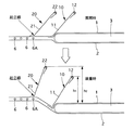
一方、図2に詳細が示されているように、不透液性バックシート2と第2バリヤーシート21との間に、ガスケットカフス用弾性伸縮部材6が、図示例においては、着用者の肌に対する当たりを柔らかくするために、幅方向に間隔を置いて複数本、具体的には4本それらの一方または両方にホットメルト接着剤などにより、伸長下で固定されている。
【0019】
第1バリヤーシート11は、その外側部分が吸収体3の側縁から、ガスケットカフス用弾性伸縮部材6,6…群の最も製品幅方向中央側に位置するガスケットカフス用弾性伸縮部材6A近傍にわたって延在し、透液性トップシート1および不透液性バックシート2にホットメルト接着剤などにより固定されている。第2バリヤーシート21は、第1バリヤーシート11の外側縁部を一部覆い、その覆い部分においてホットメルト接着剤などにより固定されており、その固定の境界線が第2バリヤーカフス20の起立線とされ、その起立線の位置は、製品幅方向中央側に位置するガスケットカフス用弾性伸縮部材6A近傍とされている。好適には、ガスケットカフス用弾性伸縮部材6Aの左右に10mm以内の位置とされる。
【0020】
他方、製品の前後における少なくとも一方の端部において、腰周りを締め付ける腰バンド部が設けられ、かつ使用面側に端部バリヤーカフス50を備えている。
【0021】
図示例においては、予め結合テープ70を設けた背側に、端部バリヤーカフス50が設けられている。
【0022】
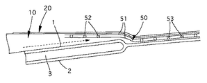
前記端部バリヤーカフス50は、バリヤーシート51を有し、製品の中央側が前記透液性トップシート1と固定されておらず、この非固定部分において製品の幅方向に沿う起立用弾性伸縮部材52が設けられ、使用時において、その起立用弾性伸縮部材52の収縮により、前記非固定部分が前記透液性トップシート1と離間するように構成され、端部バリヤーカフス50の製品の端縁側は製品の本体(図示例においては図3に示すように、相互に透液性トップシート1と不透液性バックシート2とホットメルト接着剤により一体化されたフラップ部分)に一体化され、体液の前後方向漏れ防止が図られている。
【0023】
ここで、図示例においては、特に図3および図4に示されているように、バリヤーシート51は2枚の不透液性または撥水性を示すシートとされ、これら両シート51,51間に前記の起立用弾性伸縮部材52とともに、締め付け用の腰用弾性伸縮部材53が伸長状態で介在され、適宜の位置または全面においてホットメルト接着剤により一体化された腰用シート部材として予め用意され、これが製造過程において前記の製品の本体にホットメルト接着剤などにより固定される。したがって、腰用弾性伸縮部材53はバリヤーシート51,51とともに腰バンド部を構成している。
【0024】
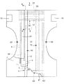
前記腰用シート部材は、図6の斜線で示すように固定されている。すなわち、製造過程において端部バリヤーカフス50を、透液性トップシート1に符号Z1で示す領域においてホットメルト接着剤などにより固定し、この固定された端部バリヤーカフス50の上から、第1バリヤーカフス10を符号Z2で示す領域においてホットメルト接着剤により固定され、さらにその上から第2バリヤーカフス20の内側部分が符号Z3で示す領域においてホットメルト接着剤により固定されている。
【0025】
したがって、前記腰用シート部材は、図6の符号Z1およびZ2の除く部分(斜線が描かれていない部分)は前述の非固定部分とされている。しかし、前記腰用シート部材(または弾性伸縮部材52,53を有して一体となったバリヤーシート51:端部バリヤーカフス50)は、透液性トップシート1および第1バリヤーカフス10に固定されているので、製品の着用時において、起立用弾性伸縮部材52の収縮により図5に示すように透液性トップシート1と離間した状態で、同図矢印で示すように、体液が移動したとしても、前記固定部分で阻止され、端部バリヤーカフス50が体液のバリヤーとして機能する。
【0026】
これに対して、製品の腹側においては、図1に示されているように、腹部腰バンド60が取付けられている。この腹部腰バンド60は、前後方向の幅が狭い2枚の不透液性または撥水性を示すシート61,61間に締め付け用の腰用弾性伸縮部材62,62…が介在され、ホットメルト接着剤などにより一体化されたものであり、全面においてホットメルト接着剤により前記腰用シート部材と同様の態様で透液性トップシート1および第1バリヤーカフス10に固定されて固定されている。したがって、腹部側においては、バリヤーカフスとしての機能は有していない。しかし、当然のことながら、この製品の腹側においても、背側と同様のバリヤーカフスを構成することができる(この態様は図示してない)。
【0027】
かかる構成の紙おむつは、着用者に装着した後、結合テープ70,70を引き出して腹側に回し、固定するものである。結合テープ70,70を除いた前記構成の紙おむつをそのままパンツタイプとすることもでき、この場合には、図1の水平中央線を境にして前後に折り畳まれ、前後両側部が、相互にヒートシールなどにより固定されることにより製品化される。
【0028】
いずれにしても、装着する場合、図2の下方に示すように、バリヤーカフス用弾性伸縮部材12,22の収縮力によって、それぞれ第1バリヤーカフス10および第2バリヤーカフス20の自由部分が起立する。また、ガスケットカフス用弾性伸縮部材6,6…(6Aも含めて)の収縮力が作用するので、ガスケットカフス用弾性伸縮部材6Aの左方部分が、吸収体3が存在せず、易変形領域を構成しているので、着用者の肌により密着するように着用者側に持ち上がるようになる。
【0029】
その結果、仮に、第1バリヤーカフス10および第2バリヤーカフス20の自由部分の長さが同一であったとしても、図2の下方に示すように、ガスケットカフス用弾性伸縮部材6,6…(6Aも含めて)の収縮力によって第2バリヤーカフス20の自由部分はより大きく起立するようになり、起立縁の透液性トップシート1からの起立高さh2 は、第1バリヤーカフス10の起立高さh1 より高くなる。
【0030】
<側部構造の作用効果>
かかる側部構造を示す態様においては、次記のとおりの利点をもたらす。
(1)第1バリヤーカフス10のほか、第2バリヤーカフス20があるために、第1バリヤーカフス10によって阻止できなった体液(軟便も含む)を、第2バリヤーカフス20で阻止できる。
【0031】
(2)ガスケットカフス用弾性伸縮部材6,6…(6Aも含めて)の収縮力によって第2バリヤーカフス20の自由部分はより大きく起立するので、たとえば図2のh2 >h1 にあるときには、第1バリヤーカフス10によって阻止できなった体液(軟便も含む)を第2バリヤーカフス20で阻止する機能がより顕著にあらわれる。
【0032】
(3)第2バリヤーカフス20の自由部分はより鉛直(図2基準)方向に起立するので、第1バリヤーカフス10の自由部分と第2バリヤーカフス20の自由部分との間隔または空間が(展開状態より)大きくなり、第1バリヤーカフス10によって阻止できなくこれを越えた体液をその間において保持できるようになり、第2バリヤーカフス20で阻止する機能が顕著にあらわれる。
【0033】
(4)前記(2)および(3)の結果、第2バリヤーカフス20のバリヤーカフス用弾性伸縮部材22の収縮力を弱めても差し支えなくなるので、着用者に対する過度の圧迫から解放できる。
【0034】
(5)ガスケットカフス用弾性伸縮部材6,6…(6Aも含めて)は、第2バリヤーカフス20の起立効果を高めるほか、それ自体で、製品の脚周り部分を着用者にフィットさせ、また、仮に第2バリヤーカフス20を体液が越えたとしても、そこで阻止できるとともに、第2バリヤーカフス20が液分で湿潤したとき、それ以上の外方への湿潤を阻止し、防湿性を高める。
【0035】
さらに、ガスケットカフス用弾性伸縮部材6,6…の収縮力作用領域が着用者の脚周り部分にフィットするので、第1バリヤーカフス10の自由部分と第2バリヤーカフス20の自由部分が、それ以上に外側に折り返されてはみ出ることがなく、かつ、常に内側に向いて起立し、本来のバリヤーカフスの機能を良好に発揮する。
【0036】
(6)ガスケットカフス用弾性伸縮部材6,6…を付加することで、上記の機能が十全に発揮されるため、第1バリヤーカフス10の自由部分より第2バリヤーカフス20の自由部分の幅方向は小さくでき、かつ、コストの上昇は殆どなく、しかも、全体の機能とのバランスからして、コスト的には極めて優れたものとなる。具体的には、第1バリヤーカフス10の自由部分を30〜50mmとしたとき、第1バリヤーカフス10の起立線と第2バリヤーカフス20の起立線との間の易変形領域が第2バリヤーカフス20の自由部分と連動するので、第2バリヤーカフス20の自由部分は第1バリヤーカフス10の自由部分より20〜40mm小さくできる。
【0037】
(7)第1バリヤーカフス10の起立線と第2バリヤーカフス20の起立線との間を離すことで、ガスケットカフス用弾性伸縮部材6,6…の収縮力によって、第1バリヤーカフス10と第2バリヤーカフス20との間にポケット(各バリヤーカフスの自由部分間の空間)ができ、第1バリヤーカフス10で阻止できなかった体液(軟便も含む)を第2バリヤーカフス20で阻止する機能が顕著にあらわれる。具体的には、第1バリヤーカフス10の起立線と第2バリヤーカフス20の起立線とは10〜40mm離間させることが望ましい。
【0038】
<端部バリヤーカフスの作用効果>
前記の実施の態様により次記の作用効果を奏する。
(ア)製品の前後における少なくとも一方の端部において、腰周りを締め付ける腰バンド部が設けられ、かつ、好適には少なくとも背側の使用面側に端部バリヤーカフス50が設けられている。しかも、この端部バリヤーカフス50には、その非固定部分において製品の幅方向に沿う起立用弾性伸縮部材52が設けられているので、製品の使用時において、起立用弾性伸縮部材52の収縮力によりその非固定部分が収縮し、透液性トップシート1と確実に離間する。すなわち、起立用弾性伸縮部材52の収縮力によりその非固定部分が反り返ったり(従来例)することなく、着用者の肌に確実に接触し、体液のバリヤー機能が十分に発揮される。
【0039】
(イ)端部バリヤーカフス50を形成する場合において、腰バンドと別に単独で形成することも考えられるが、これらが別であると、一般的には、製造過程においてそれらの位置決めが煩雑となり、かつ製品の見栄えも悪い。しかるに、バリヤーシート51に対して起立用弾性伸縮部材52とともに、締め付け用の腰用弾性伸縮部材53が伸長状態で介在し、適宜の位置または全面においてホットメルト接着剤により一体化された腰用シート部材として予め用意され、これが製造過程において前記の製品の本体にホットメルト接着剤などにより固定するようにすると、端部バリヤーカフス50の位置決めが容易となり、製品の見栄えに優れたものとなる。
【0040】
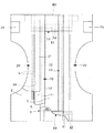
(本発明の実施の形態)
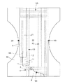
図7は、本発明の実施の形態例を示したもので、前記腰用シート部材は、図7の斜線で示すように固定されている。すなわち、製造過程において第1バリヤーカフス10の内側部分の前後方向両端部は符号Z4で示す領域において透液性トップシート1にホットメルト接着剤などにより固定され、この固定された第1バリヤーカフス10の上から端部バリヤーカフス50が符号Z5で示す領域においてホットメルト接着剤により固定され、その後、その上から第2バリヤーカフス20の内側部分が符号Z6で示す領域においてホットメルト接着剤により固定されて、前記腰用シート部材と一体化される。
【0041】
したがって、前記腰用シート部材は、図7の符号Z4およびZ5を除く部分(斜線が描かれていない部分)は前述の非固定部分とされている。
図1及び図6に示す第1の参考実施の形態下において、前記腰用シート部材(または弾性伸縮部材52,53を有して一体となったバリヤーシート51:端部バリヤーカフス50)は、透液性トップシート1および第1バリヤーカフス10に固定されているので、製品の着用時において、起立用弾性伸縮部材52の収縮により図5に示すように透液性トップシート1と離間した状態で、同図矢印で示すように、体液が移動したとしても、前記固定部分で阻止され、端部バリヤーカフス50が体液のバリヤーとして機能する。
【0042】
図7に示す本発明の実施の形態では、端部バリヤーカフス50は第2バリヤーカフス20の下にある。このために見栄えに優れるとともに、図7に示されているように、端部バリヤーカフス50と第2バリヤーカフス20との重なり部分が第1バリヤーカフス10に対してフリー(非固定)であると、起立用弾性伸縮部材52の収縮力の作用する長さ区間が長くなり、前後漏れ防止効果に優れる。また、第1バリヤーカフス10を越えて第2バリヤーカフス20との間に横漏れした体液が前後端部に移動した場合であっても、前記の重なり部分においてそれを阻止でき、前後漏れを防止できる。
【0043】
この例においても、バリヤーシート51は2枚の不透液性または撥水性を示すシートとされ、これら両シート51,51間に前記の起立用弾性伸縮部材52とともに、締め付け用の腰用弾性伸縮部材53が伸長状態で介在され、適宜の位置または全面においてホットメルト接着剤により一体化された腰用シート部材として予め用意され、これが製造過程において前記の製品の本体にホットメルト接着剤などにより固定される。したがって、腰用弾性伸縮部材53はバリヤーシート51,51とともに腰バンド部を構成している。
【0044】
(第2の参考実施の形態)
図8および図9は第2の参考実施の形態例を示したものである。この例においては、主にパンツタイプの紙おむつとして好適に使用されるものであり、前述の実施の形態と主に異なるところは、本体バックシートを設けた点である。
【0045】
すなわち、不織布などからなる透液性トップシート1とポリエチレンシートなどからなる不透液性バックシート2とにより吸収体3を包んだ構造の吸収体要素4が、本体バックシート30に設けられている。
【0046】
本体バックシート30は、最終製品の外面全体に及んで全体形状を規定する連続シートであり、たとえば、前後方向および幅方向の少なくとも一方向において弾性伸縮性を示す材料からなり、その弾性伸縮度は150%以上である。実施例での本体バックシート30は砂時計形状に成形されている。この本体バックシートは、ムレ防止などの点から、通気性および防水性(撥水性)の少なくとも一方、より好ましくは両者の特性を有するのが望まれる。その素材は適宜選択できるが、その例としては、ポリプロピレン主体の熱融着繊維とレーヨン繊維を混綿したレーヨンスパンレース不織布と、ウレタンやイソプレンゴム系の材料を主体とするメルトブロー不織布を熱融着、超音波接合、ホットメルト接着剤による接合などにより一体化し、前者の不織布を着用者の肌側に使用するものを挙げることができる。
【0047】
前記本体バックシート30に対して、製品幅方向中央側に第1バリヤーカフス10が、外側に第2バリヤーカフス20が固定されている。
【0048】
これらの第1および第2バリヤーカフス10,20は好ましくは不透液性または撥水性を示す第1および第2バリヤーシート11,21を有する。第1バリヤーシート11の起立線は吸収体3の側縁部にあり、第2バリヤーシート21の起立線は、吸収体3の側縁より外方の易変形領域にあり、本体バックシート30に対してそれぞれの外方部分がホットメルト接着剤などにより固定されている。
【0049】
製品の前後において、前後端部バリヤーカフス50,50が設けられている。
【0050】
図9に詳細が示されているように、本体バックシート30と第2バリヤーシート21との間に、ガスケットカフス用弾性伸縮部材6が、図示例においては、着用者の肌に対する当たりを柔らかくするために、幅方向に間隔を置いて複数本、具体的には4本それらの一方または両方にホットメルト接着剤などにより、伸長下で固定されている。
【0051】
第1バリヤーシート11は、その外側部分が吸収体3の側縁から、ガスケットカフス用弾性伸縮部材6,6…群の最も製品幅方向中央側に位置するガスケットカフス用弾性伸縮部材6A近傍にわたって延在し、透液性トップシート1および本体バックシート30にホットメルト接着剤などにより固定されている。第2バリヤーシート21は、第1バリヤーシート11の外側縁部を一部覆い、その覆い部分においてホットメルト接着剤などにより固定されており、その固定の境界線が第2バリヤーカフス20の起立線とされ、その起立線の位置は、製品幅方向中央側に位置するガスケットカフス用弾性伸縮部材6A近傍とされている。
【0052】
かかる構成の紙おむつは、パンツタイプの場合において、図8の水平中央線を境にして前後に折り畳まれ、本体バックシート30の前後両側部が、相互にヒートシールなどにより固定されることにより製品化される。
【0053】
(変形例:これらの各例は各請求項記載の実施の態様の範囲内である)
図10は、第1バリヤーカフス10と第2バリヤーカフス20とを構成するバリヤーシート40を幅方向に連続する一枚のシートで形成した例である。第2バリヤーカフス20においては、バリヤーシート40が2重である。
【0054】
図11は、第1バリヤーカフス10の第1バリヤーシート11を延在し、その上に第2バリヤーカフス20の第2バリヤーシート21を固定したものである。
【0055】
図12は、第1バリヤーカフス10と第2バリヤーカフス20とを構成するバリヤーシート41を幅方向に連続する一枚のシートで形成した例である。ただし、透液性トップシート1が製品の外方に延在し、これにバリヤーシート41が固定されている。
【0056】
一方、図2に戻ると、この例においては、第2バリヤーカフス20の起立線がガスケットカフス用弾性伸縮部材6Aに対応する位置にあるが、ガスケットカフス用弾性伸縮部材6,6,6,6Aの収縮力作用領域の幅方向中間より製品幅方向中央側にある限り、基本的に前述の機能を発揮して第2バリヤーカフス20が起立する。
【0057】
【0058】
前記各弾性伸縮部材の本数は適宜の本数とすることができるとともに、その部材としては糸ゴムのほか、帯状の伸縮性バンドなどでもよい。
【0059】
端部バリヤーカフス50のバリヤーシート51としては、好ましくは伸縮性を有する材質からなるものであるが、伸縮性を有しなくともよい。
【0060】
(第3の参考実施の形態)
図13は第3の参考実施の形態を示したもので、端部バリヤーカフス50における締め付け用の腰用弾性伸縮部材53を無くし、その代わりに別のたとえばウレタン発泡体などからなる腰バンド80を別体で設けたものである。腰バンド80はたとえば透液性トップシート1と不透液性バックシート2との間に伸長下で設けることができる。
【0061】
(第4の参考実施の形態)
図14は第4の参考実施の形態であり、側部バリヤーカフス100を一つのものとした例である。すなわち、側部バリヤーカフス100は、好ましくは不透液性または撥水性を示すバリヤーシート101を有し、これが不透液性バックシート2にホットメルト接着剤などにより固定されており、その内側部分が着用者側に起立するように、糸ゴムなどからなる側部バリヤーカフス用弾性伸縮部材102がその伸張下でホットメルト接着剤などにより固定されたものである。
【0062】
(第5の参考実施の形態)
図15は第5の参考実施の形態であり、一つの側部バリヤーカフス100を有する形態の下で、端部バリヤーカフス50は締め付け用の腰用弾性伸縮部材53を有しておらず、その代わりに別のたとえばウレタン発泡体などからなる腰バンド80が別体で設けられたものである。図15の斜線部分は、透液性トップシート1および不透液性バックシート2に対してのホットメルト接着剤による固定領域例を示している。
【0063】
(その他)
上記の各実施の形態の組み合わせ変形例が多々あることは明らかであろう。また、各弾性伸縮部材の伸縮力は適宜選択でき、かつ相違していてもよい。
【0064】
【発明の効果】
以上のとおり、本発明によれば、前後漏れ防止効果に優れたものとなる。
【図面の簡単な説明】
【図1】 第1の参考実施の形態に従う紙おむつの展開状態の平面図である。
【図2】 図1の部分横断面図である。
【図3】 図1の3−3線矢視図である。
【図4】 図1の4−4線矢視図である。
【図5】 使用状態における図1の4−4線矢視図である。
【図6】 図1の部分拡大図である。
【図7】 本発明の実施の形態に従う紙おむつの展開状態平面図の部分拡大図である。
【図8】 第2の参考実施の形態に従う紙おむつの展開状態の平面図である。
【図9】 図8の部分横断面図である。
【図10】 変形例の側部バリヤーカフス構造例の横断面図である。
【図11】 他の変形例の側部バリヤーカフス構造例の横断面図である。
【図12】 別の変形例の側部バリヤーカフス構造例の横断面図である。
【図13】 第3の参考実施の形態を示す紙おむつの展開状態平面図である。
【図14】 第4の参考実施の形態を示す紙おむつの展開状態平面図である。
【図15】 第5の参考実施の形態を示す紙おむつの展開状態平面図である。
【符号の説明】
1…透液性トップシート、2…不透液性バックシート、3…吸収体、4…吸収体要素、6,6A…ガスケットカフス用弾性伸縮部材、10…第1バリヤーカフス、11…第1バリヤーシート、12…第1バリヤーカフス用弾性伸縮部材、20…第2バリヤーカフス、21…第2バリヤーシート、22…第2バリヤーカフス用弾性伸縮部材、30…本体バックシート、50…端部バリヤーカフス、51…バリヤーシート、52…起立用弾性伸縮部材、53…締め付け用の腰用弾性伸縮部材、60…腹部腰バンド、80…腰バンド。[0001]
[Industrial application fields]
The present invention relates to a disposable paper diaper, for example, a disposable paper diaper to be mounted using a pants type such as so-called training pants or a binding tape.
[0002]
[Prior art]
Disposable disposable diapers, especially training pants, are used to promote separation of disposable diapers during the transition from infants to infants.
[0003]
Various proposals have been made on this type of pants-type paper diaper or on a paper diaper using a binding tape.
[0004]
In any disposable diaper, preventing leakage of body fluids from around the waist is a necessary characteristic of the product, and in recent years, forming side barrier cuffs is a general-purpose technology to prevent side leakage of loose stool. It is said that.
[0005]
In many products currently on the market, there is one side barrier cuff on each side, but in Japanese Patent Application Laid-Open No. 63-21901 and Utility Model Registration No. 2523726, there are two side parts on each side. It has been proposed to provide a barrier cuff.
[0006]
On the other hand, in addition to the above-mentioned lateral leakage, in particular for the longitudinal leakage that occurs when the wearer is sleeping, a device having an end barrier cuff is proposed as described in JP-A-3-136653. Yes.
[0007]
[Problems to be solved by the invention]
However, even if the end barrier cuff described in JP-A-3-136653 is provided for front and back leakage, the end barrier cuff is warped or separated from the wearer's skin. There was a limit to trying to completely prevent back-and-forth leakage with only the waistband.
[0008]
Further, it has been found that even if two side barrier cuffs are provided on each side, the side leakage cuff is more effective than the case where one barrier cuff is formed, but the effect is not necessarily remarkable.
[0009]
Therefore, the subject of this invention is providing the paper diaper which the effect of preventing back-and-front leakage appears notably.
[0010]
[Means for Solving the Problems]
The invention according to
(1) A second portion having an elastic stretchable member in the vicinity of the tip, and a free portion standing on the wearer side at the time of wearing by a contraction force of the elastic stretchable member, with a standing line formed by a fixing region formed by a hot-melt adhesive . With barrier cuffs,
An elastic expansion / contraction member is provided in the vicinity of the tip, and when the free part is mounted due to the contraction force of the elastic expansion / contraction member with a standing line formed by a fixing region by a hot melt adhesive on the center side in the product width direction from the second barrier cuff A first barrier cuff standing on the wearer side in
(2) At least one end portion before and after the product is provided with an end barrier cuff having an edge side fixing portion and a center side portion on the use surface side of the product body,
A longitudinal end corresponding to the free portion of each first barrier cuff is fixed on the liquid-permeable top sheet by a hot melt adhesive,
The edge side fixing portion of the end barrier cuff is fixed by a hot melt adhesive on the liquid-permeable top sheet and on a longitudinal end corresponding to the free portion of each first barrier cuff,
A longitudinal end corresponding to a free portion of each of the second barrier cuffs is fixed on the edge side fixing portion of the end barrier cuff by a hot melt adhesive,
The end barrier cuff is provided with an elastic stretch member along the width direction of the product at the center side portion, and the center side portion of the end barrier cuff is not fixed to each first barrier cuff and The second barrier cuff is fixed to the lower surface of the free part, and is not fixed to the liquid-permeable top sheet, and is an unfixed part. At the time of mounting, the elastic elastic member contracts along the width direction. The non-fixed portion is configured to be separated from the liquid-permeable top sheet.
It is a disposable paper diaper characterized by this.
[0011]
The invention according to
[0012]
A third aspect of the present invention is the disposable paper diaper according to the first aspect, wherein a waist band for tightening around the waist is provided separately from the waist seat member constituting the end barrier cuff .
[0013]
DETAILED DESCRIPTION OF THE INVENTION
Hereinafter, the present invention will be described in more detail with reference to embodiments shown in the drawings.
(First Reference Embodiment )
1 to 6 show a first reference embodiment of a disposable paper diaper to be mounted using a binding tape. As shown in FIGS. 1 and 2, the overall structure is a transparent sheet made of nonwoven fabric or the like. It has a structure in which the
[0014]
The side part of the liquid-
[0015]
Furthermore, the
[0016]
The first and
[0017]
Further, the first and
[0018]
On the other hand, as shown in detail in FIG. 2, between the liquid-
[0019]
The
[0020]
On the other hand, a waist band portion for tightening around the waist is provided at at least one end portion before and after the product, and an
[0021]
In the illustrated example, an
[0022]
The
[0023]
Here, in the illustrated example, as particularly shown in FIG. 3 and FIG. 4, the
[0024]
The waist sheet member is fixed as shown by the hatched lines in FIG. That is, in the manufacturing process, the
[0025]
Therefore, in the lumbar sheet member, the portions excluding the symbols Z1 and Z2 in FIG. 6 (portions where hatched lines are not drawn) are the above-described non-fixed portions. However, the waist sheet member (or the
[0026]
On the other hand, on the abdomen side of the product, as shown in FIG. 1, an
[0027]
The paper diaper having such a configuration is to be fixed by pulling out the connecting
[0028]
In any case, as shown in the lower part of FIG. 2, the free portions of the
[0029]
As a result, even if the lengths of the free portions of the
[0030]
<Effects of side structure>
In the aspect showing such a side part structure, the following advantages are brought about.
(1) Since there is the
[0031]
(2) Since the free portion of the
[0032]
(3) Since the free portion of the
[0033]
(4) As a result of the above (2) and (3), even if the contraction force of the
[0034]
(5) The elastic
[0035]
In addition, since the contraction force action region of the elastic expansion /
[0036]
(6) By adding the elastic
[0037]
(7) By separating the rising line of the
[0038]
<Effects of end barrier cuffs>
According to the embodiment described above, the following operational effects are obtained.
(A) A waist band portion for tightening around the waist is provided at at least one end portion before and after the product , and an
[0039]
(A) In the case of forming the end barrier cuffs 50, it may be possible to form them separately from the waist band. However, if these are separate, in general, positioning them in the manufacturing process becomes complicated, And the product looks bad. However, a waist elastic
[0040]
( Embodiment of the present invention )
FIG. 7 shows an embodiment of the present invention , and the waist seat member is fixed as shown by the oblique lines in FIG. That is, in the manufacturing process, both end portions in the front-rear direction of the inner part of the
[0041]
Therefore, in the lumbar sheet member, the portions other than the symbols Z4 and Z5 in FIG. 7 (portions where hatched lines are not drawn) are the aforementioned non-fixed portions.
Under the first embodiment shown in FIGS. 1 and 6, the waist sheet member (or the
[0042]
In the embodiment of the invention shown in FIG. 7 , the
[0043]
Also in this example, the
[0044]
( Second reference embodiment )
8 and 9 show a second reference embodiment . In this example, it is mainly used suitably as a pants-type paper diaper, and the main difference from the above-described embodiment is that a main body back sheet is provided.
[0045]
That is, the
[0046]
The main body back
[0047]
Wherein for the
[0048]
These first and second barrier cuffs 10 and 20 preferably have first and
[0049]
Front and rear end barrier cuffs 50, 50 are provided before and after the product.
[0050]
As shown in detail in FIG. 9, between the main body back
[0051]
The
[0052]
In the case of the pants type, the paper diaper having such a configuration is folded back and forth with the horizontal center line in FIG. 8 as a boundary, and the front and rear side portions of the
[0053]
(Modifications: Each of these examples is within the scope of the embodiments described in each claim)
FIG. 10 shows an example in which the
[0054]
In FIG. 11, the
[0055]
FIG. 12 shows an example in which the
[0056]
On the other hand, referring back to FIG. 2, in this example, the standing line of the
[0057]
[0058]
The number of the elastic elastic members can be an appropriate number, and the member may be a rubber band, a belt-like elastic band, or the like.
[0059]
The
[0060]
( Third reference embodiment )
FIG. 13 shows a third reference embodiment in which the elastic
[0061]
( Fourth embodiment )
FIG. 14 shows a fourth embodiment, which is an example in which one
[0062]
( Fifth embodiment )
FIG. 15 shows a fifth reference embodiment. In the embodiment having one
[0063]
(Other)
It will be apparent that there are many variations of combinations of the above embodiments. Moreover, the elastic force of each elastic elastic member can be selected as appropriate, and may be different.
[0064]
【The invention's effect】
As described above, according to the present invention, the front-rear leakage prevention effect is excellent.
[Brief description of the drawings]
FIG. 1 is a plan view of a developed state of a disposable diaper according to a first reference embodiment .
FIG. 2 is a partial cross-sectional view of FIG.
FIG. 3 is a view taken along line 3-3 in FIG. 1;
4 is a view taken along line 4-4 in FIG. 1;
5 is a view taken along line 4-4 of FIG. 1 in a use state.
6 is a partially enlarged view of FIG. 1. FIG.
FIG. 7 is a partially enlarged view of the developed state plan view of the disposable diaper according to the embodiment of the present invention .
FIG. 8 is a plan view of a developed state of the disposable diaper according to the second reference embodiment .
FIG. 9 is a partial cross-sectional view of FIG.
FIG. 10 is a cross-sectional view of a modified example of a side barrier cuff structure.
FIG. 11 is a cross-sectional view of an example of a side barrier cuff structure according to another modification.
FIG. 12 is a cross-sectional view of another modified example of a side barrier cuff structure.
FIG. 13 is a developed state plan view of a disposable diaper showing a third reference embodiment .
FIG. 14 is a developed plan view of a disposable diaper showing a fourth reference embodiment .
FIG. 15 is a developed state plan view of a disposable diaper showing a fifth reference embodiment .
[Explanation of symbols]
DESCRIPTION OF
Claims (3)
(1)先端付近に弾性伸縮部材を有し、ホットメルト接着剤による固定領域がなす起立線を境に自由部分が、前記弾性伸縮部材の収縮力により装着時において着用者側に起立する第2バリヤーカフスと、
先端付近に弾性伸縮部材を有し、前記第2バリヤーカフスより製品幅方向中央側にホットメルト接着剤による固定領域がなす起立線を境に自由部分が、前記弾性伸縮部材の収縮力により装着時において着用者側に起立する第1バリヤーカフスとを有し、
(2)製品の前後における少なくとも一方の端部において、端縁側固定部分及び中央側部分を有する端部バリヤーカフスを製品本体の使用面側に備え、
前記各第1バリヤーカフスの前記自由部分相当の長手方向端部は、前記透液性トップシート上にホットメルト接着剤により固定され、
前記端部バリヤーカフスの前記端縁側固定部分は、前記透液性トップシート上及び前記各第1バリヤーカフスの前記自由部分相当の長手方向端部上に、ホットメルト接着剤により固定され、
前記各第2バリヤーカフスの自由部分相当の長手方向端部は、前記端部バリヤーカフスの前記端縁側固定部分上に、ホットメルト接着剤により固定され、
前記端部バリヤーカフスは、前記中央側部分において製品の幅方向に沿う弾性伸縮部材が設けられ、前記端部バリヤーカフスの前記中央側部分は、前記各第1バリヤーカフスに対して非固定でかつ前記各第2バリヤーカフスの自由部分の下面に固定され、さらに、前記透液性トップシートと固定されておらず非固定部分とされ、装着時において、前記幅方向に沿う弾性伸縮部材の収縮により、前記非固定部分が前記透液性トップシートと離間するように構成されている、
ことを特徴とする使い捨て紙おむつ。In a paper diaper having side barrier cuffs on both sides of the use surface side of the product body having an absorbent body between the liquid-permeable top sheet and the liquid-impermeable back sheet,
(1) A second portion having an elastic stretchable member in the vicinity of the tip, and a free portion standing on the wearer side at the time of wearing by a contraction force of the elastic stretchable member, with a standing line formed by a fixing region formed by a hot-melt adhesive . With barrier cuffs,
An elastic expansion / contraction member is provided in the vicinity of the tip, and when the free part is mounted due to the contraction force of the elastic expansion / contraction member with a standing line formed by a fixing region by a hot melt adhesive on the center side in the product width direction from the second barrier cuff A first barrier cuff standing on the wearer side in
(2) At least one end portion before and after the product is provided with an end barrier cuff having an edge side fixing portion and a center side portion on the use surface side of the product body,
A longitudinal end corresponding to the free portion of each first barrier cuff is fixed on the liquid-permeable top sheet by a hot melt adhesive,
The edge side fixing portion of the end barrier cuff is fixed by a hot melt adhesive on the liquid-permeable top sheet and on a longitudinal end corresponding to the free portion of each first barrier cuff,
A longitudinal end corresponding to a free portion of each of the second barrier cuffs is fixed on the edge side fixing portion of the end barrier cuff by a hot melt adhesive,
The end barrier cuff is provided with an elastic stretch member along the width direction of the product at the center side portion, and the center side portion of the end barrier cuff is not fixed to each first barrier cuff and The second barrier cuff is fixed to the lower surface of the free part, and is not fixed to the liquid-permeable top sheet, and is an unfixed part. At the time of mounting, the elastic elastic member contracts along the width direction. The non-fixed portion is configured to be separated from the liquid-permeable top sheet.
A disposable paper diaper characterized by that.
Priority Applications (1)
| Application Number | Priority Date | Filing Date | Title |
|---|---|---|---|
| JP13828297A JP3856904B2 (en) | 1997-05-28 | 1997-05-28 | Disposable paper diapers |
Applications Claiming Priority (1)
| Application Number | Priority Date | Filing Date | Title |
|---|---|---|---|
| JP13828297A JP3856904B2 (en) | 1997-05-28 | 1997-05-28 | Disposable paper diapers |
Related Child Applications (1)
| Application Number | Title | Priority Date | Filing Date |
|---|---|---|---|
| JP2005352018A Division JP4769077B2 (en) | 2005-12-06 | 2005-12-06 | Disposable paper diapers |
Publications (2)
| Publication Number | Publication Date |
|---|---|
| JPH10328234A JPH10328234A (en) | 1998-12-15 |
| JP3856904B2 true JP3856904B2 (en) | 2006-12-13 |
Family
ID=15218268
Family Applications (1)
| Application Number | Title | Priority Date | Filing Date |
|---|---|---|---|
| JP13828297A Expired - Lifetime JP3856904B2 (en) | 1997-05-28 | 1997-05-28 | Disposable paper diapers |
Country Status (1)
| Country | Link |
|---|---|
| JP (1) | JP3856904B2 (en) |
Cited By (10)
| Publication number | Priority date | Publication date | Assignee | Title |
|---|---|---|---|---|
| US10485710B2 (en) | 2015-03-18 | 2019-11-26 | The Procter & Gamble Company | Absorbent article with leg cuffs |
| US10524963B2 (en) | 2015-03-18 | 2020-01-07 | The Procter & Gamble Company | Absorbent article with waist gasketing element and leg cuffs |
| US10524962B2 (en) | 2015-03-18 | 2020-01-07 | The Procter & Gamble Company | Absorbent article with waist gasketing element and leg cuffs |
| US10531991B2 (en) | 2015-03-18 | 2020-01-14 | The Procter & Gamble Company | Absorbent article with waist gasketing element and leg cuffs |
| US10531990B2 (en) | 2015-03-18 | 2020-01-14 | The Procter & Gamble Company | Absorbent article with leg cuffs |
| US10537481B2 (en) | 2015-03-18 | 2020-01-21 | The Procter & Gamble Company | Absorbent article with waist gasketing element and leg cuffs |
| US10543131B2 (en) | 2015-03-18 | 2020-01-28 | The Procter & Gamble Company | Absorbent article with leg cuffs |
| US10588790B2 (en) | 2015-03-18 | 2020-03-17 | The Procter & Gamble Company | Absorbent article with leg cuffs |
| US10716716B2 (en) | 2015-03-18 | 2020-07-21 | The Procter & Gamble Company | Absorbent article with leg cuffs |
| US10792198B2 (en) | 2015-03-18 | 2020-10-06 | The Procter & Gamble Company | Absorbent article with leg cuffs |
Families Citing this family (6)
| Publication number | Priority date | Publication date | Assignee | Title |
|---|---|---|---|---|
| JP2000288013A (en) * | 1999-04-09 | 2000-10-17 | Kao Corp | Absorptive article |
| KR100861634B1 (en) | 1999-07-14 | 2008-10-07 | 다이오 페이퍼 코퍼레이션 | Disposable absorbing article |
| JP2006247273A (en) * | 2005-03-14 | 2006-09-21 | Uni Charm Corp | Disposable wearing article |
| JP4480688B2 (en) * | 2005-03-23 | 2010-06-16 | 花王株式会社 | Absorbent articles |
| JP4638368B2 (en) * | 2006-03-27 | 2011-02-23 | 大王製紙株式会社 | Disposable absorbent article |
| US8795250B2 (en) * | 2010-03-30 | 2014-08-05 | First Quality Baby Products, Llc | Absorbent article having leg cuffs |
-
1997
- 1997-05-28 JP JP13828297A patent/JP3856904B2/en not_active Expired - Lifetime
Cited By (24)
| Publication number | Priority date | Publication date | Assignee | Title |
|---|---|---|---|---|
| US10485710B2 (en) | 2015-03-18 | 2019-11-26 | The Procter & Gamble Company | Absorbent article with leg cuffs |
| US10524963B2 (en) | 2015-03-18 | 2020-01-07 | The Procter & Gamble Company | Absorbent article with waist gasketing element and leg cuffs |
| US10524962B2 (en) | 2015-03-18 | 2020-01-07 | The Procter & Gamble Company | Absorbent article with waist gasketing element and leg cuffs |
| US10531991B2 (en) | 2015-03-18 | 2020-01-14 | The Procter & Gamble Company | Absorbent article with waist gasketing element and leg cuffs |
| US10531990B2 (en) | 2015-03-18 | 2020-01-14 | The Procter & Gamble Company | Absorbent article with leg cuffs |
| US10537481B2 (en) | 2015-03-18 | 2020-01-21 | The Procter & Gamble Company | Absorbent article with waist gasketing element and leg cuffs |
| US10543131B2 (en) | 2015-03-18 | 2020-01-28 | The Procter & Gamble Company | Absorbent article with leg cuffs |
| US10543130B2 (en) | 2015-03-18 | 2020-01-28 | The Procter & Gamble Company | Absorbent article with leg cuffs |
| US10583049B2 (en) | 2015-03-18 | 2020-03-10 | The Procter & Gamble Company | Absorbent article with waist gasketing element and leg cuffs |
| US10588791B2 (en) | 2015-03-18 | 2020-03-17 | The Procter & Gamble Company | Absorbent article with waist gasketing element and leg cuffs |
| US10588790B2 (en) | 2015-03-18 | 2020-03-17 | The Procter & Gamble Company | Absorbent article with leg cuffs |
| US10588789B2 (en) | 2015-03-18 | 2020-03-17 | The Procter & Gamble Company | Absorbent article with leg cuffs |
| US10603226B2 (en) | 2015-03-18 | 2020-03-31 | The Procter & Gamble Company | Absorbent article with leg cuffs |
| US10716716B2 (en) | 2015-03-18 | 2020-07-21 | The Procter & Gamble Company | Absorbent article with leg cuffs |
| US10792198B2 (en) | 2015-03-18 | 2020-10-06 | The Procter & Gamble Company | Absorbent article with leg cuffs |
| US11458045B2 (en) | 2015-03-18 | 2022-10-04 | The Procter & Gamble Company | Absorbent article with leg cuffs |
| US11478385B2 (en) | 2015-03-18 | 2022-10-25 | The Procter & Gamble Company | Absorbent article with waist gasketing element and leg cuffs |
| US11504283B2 (en) | 2015-03-18 | 2022-11-22 | The Procter & Gamble Company | Absorbent article with waist gasketing element and leg cuffs |
| US11504282B2 (en) | 2015-03-18 | 2022-11-22 | The Procter & Gamble Company | Absorbent article with leg cuffs |
| US11752044B2 (en) | 2015-03-18 | 2023-09-12 | The Procter & Gamble Company | Absorbent article with leg cuffs |
| US11833012B2 (en) | 2015-03-18 | 2023-12-05 | The Procter & Gamble Company | Absorbent article with waist gasketing element and leg cuffs |
| US11844669B2 (en) | 2015-03-18 | 2023-12-19 | The Procter & Gamble Company | Absorbent article with waist gasketing element and leg cuffs |
| US11938006B2 (en) | 2015-03-18 | 2024-03-26 | The Procter & Gamble Company | Absorbent article with waist gasketing element and leg cuffs |
| US11950990B2 (en) | 2015-03-18 | 2024-04-09 | The Procter & Gamble Company | Absorbent article with waist gasketing element and leg cuffs |
Also Published As
| Publication number | Publication date |
|---|---|
| JPH10328234A (en) | 1998-12-15 |
Similar Documents
| Publication | Publication Date | Title |
|---|---|---|
| KR101255592B1 (en) | Disposable diaper | |
| JP4215370B2 (en) | Absorbent articles | |
| EP1153587B1 (en) | Absorbent article | |
| JP3856904B2 (en) | Disposable paper diapers | |
| JP5383018B2 (en) | Disposable diapers | |
| JP3382793B2 (en) | Pants-type disposable paper diapers | |
| JP2003265523A (en) | Disposable paper diaper | |
| CA2291504A1 (en) | Disposable absorbent pull-up type diapers and incontinent briefs | |
| JP2001178770A (en) | Brief type throwaway paper diaper | |
| WO2017115492A1 (en) | Disposable wearable article | |
| JPH11318978A (en) | Shorts type disposable diaper | |
| JP4198312B2 (en) | Disposable diapers | |
| JP4023880B2 (en) | Pants-type disposable paper diapers | |
| JP3703552B2 (en) | Disposable paper diapers | |
| JP3805944B2 (en) | Disposable absorbent article | |
| JP4198313B2 (en) | Disposable paper diapers | |
| US20030144645A1 (en) | Disposable pant type absorbent article having improved multifold fastening system | |
| JP2002272783A (en) | Underwear style disposable paper diaper | |
| JP4527801B2 (en) | Disposable diapers | |
| JP4769077B2 (en) | Disposable paper diapers | |
| JP3171813B2 (en) | Disposable paper diapers | |
| JP3878367B2 (en) | Pants-type disposable paper diapers | |
| JPH07328067A (en) | Disposable paper diaper | |
| JP5064671B2 (en) | Pants-type absorbent article for men | |
| JP4870735B2 (en) | Disposable diapers |
Legal Events
| Date | Code | Title | Description |
|---|---|---|---|
| A521 | Written amendment |
Free format text: JAPANESE INTERMEDIATE CODE: A523 Effective date: 20040526 |
|
| A621 | Written request for application examination |
Free format text: JAPANESE INTERMEDIATE CODE: A621 Effective date: 20040526 |
|
| A977 | Report on retrieval |
Free format text: JAPANESE INTERMEDIATE CODE: A971007 Effective date: 20050930 |
|
| A131 | Notification of reasons for refusal |
Free format text: JAPANESE INTERMEDIATE CODE: A131 Effective date: 20051007 |
|
| A521 | Written amendment |
Free format text: JAPANESE INTERMEDIATE CODE: A523 Effective date: 20051206 |
|
| TRDD | Decision of grant or rejection written | ||
| A01 | Written decision to grant a patent or to grant a registration (utility model) |
Free format text: JAPANESE INTERMEDIATE CODE: A01 Effective date: 20060818 |
|
| A61 | First payment of annual fees (during grant procedure) |
Free format text: JAPANESE INTERMEDIATE CODE: A61 Effective date: 20060913 |
|
| R150 | Certificate of patent or registration of utility model |
Free format text: JAPANESE INTERMEDIATE CODE: R150 |
|
| FPAY | Renewal fee payment (event date is renewal date of database) |
Free format text: PAYMENT UNTIL: 20090922 Year of fee payment: 3 |
|
| FPAY | Renewal fee payment (event date is renewal date of database) |
Free format text: PAYMENT UNTIL: 20090922 Year of fee payment: 3 |
|
| FPAY | Renewal fee payment (event date is renewal date of database) |
Free format text: PAYMENT UNTIL: 20100922 Year of fee payment: 4 |
|
| FPAY | Renewal fee payment (event date is renewal date of database) |
Free format text: PAYMENT UNTIL: 20100922 Year of fee payment: 4 |
|
| FPAY | Renewal fee payment (event date is renewal date of database) |
Free format text: PAYMENT UNTIL: 20100922 Year of fee payment: 4 |
|
| FPAY | Renewal fee payment (event date is renewal date of database) |
Free format text: PAYMENT UNTIL: 20110922 Year of fee payment: 5 |
|
| FPAY | Renewal fee payment (event date is renewal date of database) |
Free format text: PAYMENT UNTIL: 20110922 Year of fee payment: 5 |
|
| FPAY | Renewal fee payment (event date is renewal date of database) |
Free format text: PAYMENT UNTIL: 20120922 Year of fee payment: 6 |
|
| FPAY | Renewal fee payment (event date is renewal date of database) |
Free format text: PAYMENT UNTIL: 20120922 Year of fee payment: 6 |
|
| FPAY | Renewal fee payment (event date is renewal date of database) |
Free format text: PAYMENT UNTIL: 20120922 Year of fee payment: 6 |
|
| FPAY | Renewal fee payment (event date is renewal date of database) |
Free format text: PAYMENT UNTIL: 20130922 Year of fee payment: 7 |
|
| R250 | Receipt of annual fees |
Free format text: JAPANESE INTERMEDIATE CODE: R250 |
|
| R250 | Receipt of annual fees |
Free format text: JAPANESE INTERMEDIATE CODE: R250 |
|
| R250 | Receipt of annual fees |
Free format text: JAPANESE INTERMEDIATE CODE: R250 |
|
| R250 | Receipt of annual fees |
Free format text: JAPANESE INTERMEDIATE CODE: R250 |
|
| EXPY | Cancellation because of completion of term |