JP3856040B2 - Portable tools - Google Patents
Portable tools Download PDFInfo
- Publication number
- JP3856040B2 JP3856040B2 JP2005206352A JP2005206352A JP3856040B2 JP 3856040 B2 JP3856040 B2 JP 3856040B2 JP 2005206352 A JP2005206352 A JP 2005206352A JP 2005206352 A JP2005206352 A JP 2005206352A JP 3856040 B2 JP3856040 B2 JP 3856040B2
- Authority
- JP
- Japan
- Prior art keywords
- hook
- hook piece
- bit
- piece
- battery
- Prior art date
- Legal status (The legal status is an assumption and is not a legal conclusion. Google has not performed a legal analysis and makes no representation as to the accuracy of the status listed.)
- Expired - Lifetime
Links
Images


Description
本発明は、作業者の腰ベルト等に掛止可能なフック部を有する携帯用工具に関するものである。 The present invention relates to a portable tool having a hook portion that can be hooked on an operator's waist belt or the like.
従来の電動工具には、作業者の腰ベルト等に電動工具を掛止させるためのフック部が設けられている。このフック部が、例えば電動工具本体から突出した状態で固定配置されていると、フック部が作業中に周辺の部材等に接触してしまう。特に狭い場所で作業を行う場合にはフック部が邪魔になってしまい作業性が低下してしまう不具合があった。また、作業の邪魔になるので必要に応じてフック部を着脱可能な構成にしてしまうとフック部の紛失を引き起こす不具合があった。そこで、フック部を要しない場合には、電動工具内にフック部を収納したり、或いは作業の邪魔にならない位置までフック部を可動可能に設けていた。 A conventional power tool is provided with a hook portion for hooking the power tool on an operator's waist belt or the like. If this hook part is fixedly arranged in a state of protruding from the electric power tool body, for example, the hook part comes into contact with surrounding members and the like during work. In particular, when working in a narrow place, there is a problem that the hook portion becomes an obstacle and the workability is lowered. In addition, since it obstructs the work, there is a problem that the hook part is lost if the hook part is configured to be detachable as necessary. Therefore, when the hook portion is not required, the hook portion is movably provided up to a position where the hook portion is housed in the electric tool or does not interfere with the work.
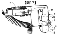
上述したフック部の一例を図17を用いて説明する。ネジが切られた棒状の鉄を折り曲げて形成された引っ掛け片2の全周に軟質材3が被覆されたフック4と、フック4を保持する保持ナット5と、フック4を抜け止めするハウジング1内に設けられた図示しない抜け止めナットで構成されている。このフック部の引っ掛け片2は、バッテリー18にほぼ隣接する収納位置から二点破線で示すように、引っ掛け片2bとハンドル9との間に形成されている隙間まで回動可能で、且つこの位置にて掛止可能に突出する。また、フックの先端が重心方向に向いた状態でベルト等に引っ掛けることで安定性が得られることから、連ネジアタッチメント7が電動工具本体から取り外され電動工具の重心位置が変化しても引っ掛け片2bを回動させることで、安定した位置に調整することができる。また、フックの引っ掛け片は、最も側方に張り出している場合が多いため、軟質材3の被覆されたフック4により電動工具を傾斜している屋根等の傾斜面に置いてもこの軟質材3により滑り止め作用が働くと共に、軟質材3により化粧板等の部材上に電動工具を置いた際に部材に傷を付けないように保護作用も働く。
An example of the hook portion described above will be described with reference to FIG. A
また、特開2000−167785号公報に開示されているように、フック部を突出固定した状態からフック全体を電動工具本体に設けた凹部内にスライド可能に収納するものもある。 Also, as disclosed in Japanese Patent Application Laid-Open No. 2000-167785, there is a type in which the entire hook is slidably housed in a recess provided in the power tool body from a state in which the hook portion is protruded and fixed.
また、上述した収納式ではないが、フック部を簡単に可動させる一例として、特開平6−285774号公報に開示されているように、電動工具の略円筒状のモーターハウジングの外周回りに回動可能で、且つフック部を係止することにより複数箇所で位置決め可能なフックもある。 Further, although not the above-described storage type, as an example of easily moving the hook portion, as disclosed in Japanese Patent Laid-Open No. 6-285774, it rotates around the outer periphery of a substantially cylindrical motor housing of the electric tool. There is also a hook that can be positioned at a plurality of locations by locking the hook portion.
また、特開平9−225861号公報に開示されているように、凸部若しくは凹部を設けたモーターハウジング左側面に嵌合可能な凸部若しくは凹部を設けた回動式のフック部が設けられ、且つこのフック部にワンタッチで着脱可能なものもある。 Further, as disclosed in JP-A-9-225861, a rotary hook portion provided with a convex portion or a concave portion that can be fitted to the left side surface of the motor housing provided with a convex portion or a concave portion is provided. Some hooks can be attached and detached with a single touch.
一方、ビット等の先端工具は、ネジ締め作業で先端を破損させ易いため、ビット交換を行う必要があるが、脚立上や足場上の高所作業でいちいち地上に置いてあるビットに交換するのは煩わしい。また、ポケット内に交換用ビットを入れておくとポケット内からネジ等を取り出す際などに落としてしまい紛失してしまう可能性が高い。このため、特開平9−216171号公報に開示されているように、ハウジングに交換用ビットを収納可能な電動工具が提供されている。このビット収納部は、ハンドルの下部に設けたバッテリー受け部の両側面にビットが衣服等に引っ掛かって落下しないように、ビットの四方全周にリブが突設されており、ビットが略完全に埋没するビット収納部が形成されている。加えてこのビット収納部内には、ビットを一ヶ所で圧着保持する係止金具が設けられており、ビットを取り出す際は係止金具を湾曲させてビット軸半径方向に引き抜けるように構成されている。 On the other hand, tip tools such as bits are easily damaged by screw tightening, so it is necessary to replace the bit. However, it is necessary to replace the bit with a bit that is placed on the ground one after another on a stepladder or on a scaffold. Is bothersome. Also, if a replacement bit is put in the pocket, there is a high possibility that it will be dropped and lost when a screw or the like is taken out from the pocket. For this reason, as disclosed in Japanese Patent Laid-Open No. 9-216171, there is provided an electric tool capable of storing a replacement bit in a housing. This bit storage part has ribs on all sides of the bit so that the bit does not fall on clothes on the both sides of the battery receiving part provided at the bottom of the handle, and the bit is almost completely A buried bit storage portion is formed. In addition, in this bit storage portion, there is provided a locking metal fitting that holds the bit in one place, and when the bit is taken out, it is configured to be bent and pulled out in the radial direction of the bit shaft. .
図17に示すフック部は、引っ掛け片の収納と引出し及び位置調節といった回動の際、いちいちスパナ等の工具による保持ナットの回転操作が必要となり面倒であるという問題があった。 The hook portion shown in FIG. 17 has a problem that it is troublesome because it requires a rotating operation of the holding nut with a tool such as a spanner every time when it is rotated such as storing and pulling the hook piece and adjusting the position.
また、特開2000−167785号公報に開示されているフック部は、安定性があり且つ簡単にフックの引き出しと収納が行える構成であるものの、モータ上部の本体内部にフックが収納できる収納部とフックがスライドできるガイド部とフックを支持する支持部とを埋設しなければならないため、電動工具が大型化してしまうという問題があった。 Further, the hook portion disclosed in Japanese Patent Laid-Open No. 2000-167785 is stable and can be easily pulled out and stored, but the hook portion can be stored inside the motor upper body. Since it is necessary to embed a guide portion that can slide the hook and a support portion that supports the hook, there is a problem that the power tool becomes large.
また、特開平6−285774号公報に開示されているフック部は、フックが電動工具の略円筒状のモーターハウジングの軸中心に回動し、モーターハウジング外周と常に一定の隙間を持ち突出している。しかしながら、フックに設けられた歯車を弾性係止するリーフスプリングを用いているため、回動方向に力を加えるとフックが簡単に回転してしまい安定性が悪いという問題があった。また、手動するロックノブでフックを固定した場合には、片手でロックを解除した状態のままもう一方の手でフックを回動させる必要があるため、操作が悪いという問題があった。 In addition, the hook portion disclosed in Japanese Patent Laid-Open No. 6-285774 is such that the hook rotates around the axis of the substantially cylindrical motor housing of the electric tool and always protrudes from the outer periphery of the motor housing with a certain gap. . However, since a leaf spring that elastically locks the gear provided on the hook is used, there is a problem that when the force is applied in the rotation direction, the hook easily rotates and the stability is poor. Further, when the hook is fixed with a manual lock knob, it is necessary to rotate the hook with the other hand while the lock is released with one hand, so that the operation is bad.
また、特開平9−225861号公報に開示されているフック部は、幅の小さい物をフックとモーターハウジングの隙間で引っ掛け、幅の大きい物をフックとハンドルの隙間で引っ掛けることができるように、フックの取付け位置を変更するというものである。しかし、素材同士の弾性係止によって回動を保持しているので、回動方向に力を加えるとフックが簡単に回動してしまい安定性が悪いという問題があった。しかも、フックをワンタッチで着脱できる保持部がモーターハウジング左側面に設けられているが、右利き左利きのどちらの作業者にも使い勝手を良くするには、モーターハウジング右側面にも保持部を設ける必要があり、この場合、フックを装着していない側の保持部は作業の邪魔になってしまうという問題があった。 In addition, the hook portion disclosed in Japanese Patent Application Laid-Open No. 9-225861 can be used to hook a small object in the gap between the hook and the motor housing, and to hook a large object in the gap between the hook and the handle. The hook mounting position is changed. However, since the rotation is held by the elastic locking between the materials, there is a problem that if the force is applied in the rotation direction, the hook easily rotates and the stability is poor. In addition, there is a holding part on the left side of the motor housing that allows you to attach and detach the hook with a single touch. To make it easier for both right-handed and left-handed workers, it is necessary to provide a holding part on the right side of the motor housing. In this case, there is a problem that the holding portion on the side where the hook is not attached interferes with the work.
一方、特開平9−216171号公報に開示されているように、モータ及びギヤを内包するモーターハウジング、ハンドル、バッテリー、バッテリー受け部、ビット収納部から構成されている。ビット収納部が設けられるべき位置を考察するに、モーターハウジングは、内部にビットを埋設するスペースがなく、且つモーターハウジングは狭い場所に滑り込ませてネジ締め作業を行うため突設させることは不適切であり、ハンドルに設けると把握し辛くなり、バッテリーに設けるとバッテリーの汎用性が低くなり、バッテリー受け部に埋設するスペースはない。このためビット収納部は、バッテリー受け部に突設される構成が望ましい。しかし、このような電動工具に、例えば図17に示すフックを設けた場合、ビット収納部にフックの引き出し片(図17)がぶつかり邪魔になると共に、引き出し片(図17)をビット収納部側方に設けた場合であっても、携帯用工具がコンパクトでなくスペース効率が悪いという問題があった。更に特開平9−216171号公報に開示されている係止金具を使用するとコストと組付け手間がかかるため、係止部はハウジングと一体に樹脂成形されたものが望ましいが、係止金具を単純に樹脂化しようとすると、樹脂は鉄より強度が弱いためビットを保持できるように肉厚を厚くする必要があり、また湾曲しビットを着脱できるように肉圧を薄くする必要もあり矛盾が生じるという問題があった。加えて、図17に示すフックに軟質材を設けた携帯用工具の一例は、引っ掛け片の全周にキャップ状の軟質材を被せてあるが、例えば引っ掛け片に特開平9−216171号公報に開示されているビット収納部を設けた場合、ビットが軟質材でカバーされ着脱不能になるか、軟質材の一部を切り欠いた場合であっても組付け作業若しくは磨耗によって切り欠いた場所から亀裂が入るという問題があった。 On the other hand, as disclosed in Japanese Patent Laid-Open No. 9-216171, the motor housing includes a motor housing containing a motor and a gear, a handle, a battery, a battery receiving portion, and a bit storage portion. Considering the position where the bit storage part should be provided, the motor housing does not have space to embed the bit inside, and it is inappropriate to project the motor housing because it slides into a narrow place and performs screw tightening work If it is provided on the handle, it will be difficult to grasp. If it is provided on the battery, the versatility of the battery will be low, and there will be no space to be embedded in the battery receiving part. For this reason, it is desirable that the bit storage portion protrudes from the battery receiving portion. However, when a hook as shown in FIG. 17 is provided in such an electric tool, for example, the hook drawer piece (FIG. 17) collides with the bit storage section, and the drawer piece (FIG. 17) is placed on the bit storage section side. Even when it is provided on the other side, there is a problem that the portable tool is not compact and space efficiency is poor. Further, since the use of the locking bracket disclosed in Japanese Patent Laid-Open No. 9-216171 is costly and troublesome, it is desirable that the locking portion is resin-molded integrally with the housing. When resin is used, the resin is weaker than iron, so it is necessary to increase the wall thickness so that the bit can be held, and it is also necessary to reduce the wall pressure so that the bit can be attached and detached. There was a problem. In addition, in the example of the portable tool in which a soft material is provided on the hook shown in FIG. 17, a cap-shaped soft material is put on the entire circumference of the hook piece. For example, Japanese Patent Laid-Open No. 9-216171 discloses a hook piece. When the disclosed bit storage part is provided, even if the bit is covered with a soft material and cannot be attached or detached, or even when a part of the soft material is cut out, it is removed from the place where it has been cut out due to assembly work or wear. There was a problem of cracks.
本発明の目的は、上記問題点を解消し、工具本体に対するフックの位置を容易に可変できる操作性に優れた電動工具を提供することである。即ち、フックの保持部への取付けが周方向の複数の位置ででき、しかも周方向に確実に保持されるフックを有する電動工具を提供することである。 An object of the present invention is to solve the above problems and to provide an electric tool with excellent operability that can easily change the position of a hook with respect to a tool body. That is, it is an object of the present invention to provide a power tool having a hook that can be attached to a holding portion of a hook at a plurality of positions in the circumferential direction and that is securely held in the circumferential direction.
上記の目的を達成するために本発明は、本体胴体部と、該本体胴体部から下方に延びるハンドル部と、該ハンドル部に設けられたフック部と、バッテリーとよりなり、前記本体胴体部には前方に先端工具保持部を収納し、後方に先端工具に伝達する回転動カを発生するモータを収納し、前記本体胴体部と反対側の前記ハンドル部には前記モータを駆動するためのバッテリーを装着可能に構成し、前記フック部は、穴部を有し且つ前記バッテリーを収納した側のハンドル部から延在する保持部と、引っ掛け片と、該引っ掛け片の一端に連設される基端部とよりなり、前記基端部は円筒状部と、該円筒状部に形成した第1の凹凸部を有し、前記保持部は前記穴部に前記第1の凹凸部と係合する第2の凹凸部を有し、前記1及び2の凹凸部を、前記引っ掛け片の先端が前方を向く第1の位置で係合可能にすると共に、係合を解除して前記引っ掛け片の先端が第1の位置より上方を向く第2の位置に移動して再び前記第1及び第2の凹凸部を係合可能に構成した携帯用工具において、前記第1の位置は、前記引っ掛け片が前記バッテリーに近接した前記引っ掛け片の収納位置であり、前記第2の位置は、前記ハンドル部と前記引っ掛け片の間に隙間ができ、前記引っ掛け片をベルトへ引っ掛ける位置としたことに一つの特徴を有する。 In order to achieve the above object, the present invention comprises a main body body portion, a handle portion extending downward from the main body body portion, a hook portion provided on the handle portion, and a battery. Is a battery for driving the motor in the handle portion on the side opposite to the main body body portion. The hook portion has a hole and has a holding portion extending from the handle portion on the side where the battery is accommodated, a hook piece, and a base connected to one end of the hook piece. The base end portion has a cylindrical portion and a first uneven portion formed in the cylindrical portion , and the holding portion engages with the first uneven portion in the hole portion. a second concave-convex portion, the concave-convex portion of the 1 and 2, wherein Engagement is enabled at the first position where the front end of the hooking piece faces forward, and the engagement is released and the front end of the hooking piece moves to the second position facing upward from the first position. In the portable tool configured to be able to engage the first and second concavo-convex portions, the first position is a storage position of the hook piece in the vicinity of the battery, and the second position The position has one characteristic in that a gap is formed between the handle portion and the hook piece, and the hook piece is hooked on the belt.
本発明によれば、工具本体に対するフックの位置を容易に可変できる操作性に優れた電動工具を提供することができる。また、フックに設けた収容保持部にビット等の先端工具を保持させることで、作業性の向上及び有効なスペース活用が図れる電動工具を提供することができる。更に収容保持部内のビット等は、確実に保持されると共に、取り外し容易に配される使い勝手に優れたフック及びその着脱方法を提供することができる。 ADVANTAGE OF THE INVENTION According to this invention, the electric tool excellent in the operativity which can change the position of the hook with respect to a tool main body easily can be provided. In addition, by holding a tip tool such as a bit in the holding holder provided on the hook, it is possible to provide an electric tool that can improve workability and effectively utilize space. Furthermore, it is possible to provide a hook that can be securely held and can be easily detached, and a method of attaching and detaching the hook, etc., that is easily removed.
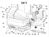
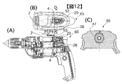
本実施例におけるインパクトドライバー等の電動工具を図1〜図16を用いて説明する。図1及び図2は本実施例における電動工具のフック部を示す要部拡大分解斜視図、図3は本実施例におけるフック部の可動状態を示しており、(A)は正面図、(B)は側面図(C)は底面図、図4は図3(A)のA−A線断面図、図5は本実施例におけるフック部をスプリング27を圧縮する方向に移動させた状態を示す図3(A)のA−A線断面図、図6は本実施例におけるフック部を反対側に装着した状態を示す外観斜視図、図7は本実施例におけるフック部の収納状態或いは突出状態を示す図4のB−B線断面図、図8は本実施例におけるフック部の回動部を示しており、(a)は図4のc−c線断面図、(b)はギヤ及びリングギヤを示す部分拡大図、図9は本実施例におけるフック部を用いて電動工具を作業者の腰ベルトに引っ掛けた状態を示す要部拡大図、図10はフック部を用いて電動工具を作業者の腰ベルトに引っ掛けた状態を示しており、(a)は電動工具を作業者の腰ベルトに引っ掛けた状態を示す説明図、(b)は(a)に示す電動工具からビットを取り外してチャックと木工錐を装着した状態を示す説明図、(c)は(a)に示す電動工具に軽量のバッテリーを装着した状態を示す説明図、図11は本実施例におけるフック部を設けた電気丸のこを示しており、(a)は一部縦断側面図、(b)は電気丸のこを梁に引っ掛けた状態を示す状態図、図12は本実施例におけるフック部を設けた電気ドリルを示しており、(a)は一部縦断正面図、(b)は一部省略平面図、(c)は(b)のd−d線断面図、図13は本実施例におけるフック部の他の例を示す要部拡大断面図、図14は本実施例におけるフック部の更に他の例を示す要部拡大断面図、図15は本実施例におけるフック部に設けたビット収納部を示す図3(a)のA−A線断面図、図16はビットを収納するフック部を示す一部外観斜視図である。
An electric power tool such as an impact driver in this embodiment will be described with reference to FIGS. FIGS. 1 and 2 are enlarged exploded perspective views showing a main part of a hook portion of an electric power tool in this embodiment, FIG. 3 shows a movable state of the hook portion in this embodiment, (A) is a front view, (B ) Is a side view (C) is a bottom view, FIG. 4 is a cross-sectional view taken along line AA in FIG. 3 (A), and FIG. 5 shows a state in which the hook portion in this embodiment is moved in the direction in which the
図3に示すように、二つ割ハウジング1(以下ハウジングと称す)及びハンマケース8などの外枠を有するインパクトドライバーは、略T字形状を成しており、ハウジング1によって形成される本体胴体部には電気式或いは空気式の駆動源であるモータ15や減速機構部を構成する遊星ギヤ部18などを収容し、且つ本体胴体部から垂下するハンドル部にはモータ15に電力を供給するためのトリガスイッチや蓄電池の接続端子と電気的に接続される接点などが収容されている。また、ハウジング1に当接して配置されるハンマケース8内にはモータ15の回転動力を打撃力に変換するための打撃機構部及びビットやレンチ等の先端工具保持部などが収容されている。
As shown in FIG. 3, an impact driver having an outer frame such as a split housing 1 (hereinafter referred to as a housing) and a hammer case 8 has a substantially T shape, and a main body body formed by the
このような構成において、モータ15の回転動力は、モータ15の出力軸であるピニオンから減速機構部に伝達され、減速機構部から打撃機構部を介して先端工具17に回転力および打撃力が伝達されている。
In such a configuration, the rotational power of the
上記打撃機構部は、スピンドル16と、スピンドル16に形成したカム溝に挿入されるスチールボール(鋼球)を介して回転可能且つ回転軸軸方向に移動可能なハンマ23と、ハンマ23に設けた複数のハンマ爪により打撃され回転するアンビル爪を有するアンビル22と、ハンマ23をアンビル22側に常に付勢するスプリングとから構成されている。
The hammering mechanism portion is provided on the hammer 16, a spindle 16, a hammer 23 that can be rotated via a steel ball (steel ball) inserted into a cam groove formed in the spindle 16 and that can move in the direction of the axis of rotation. The
上記減速機構部である遊星ギヤ部18は、ハウジング1内に回転止めを有し支持されている固定歯車支持治具、固定歯車、遊星歯車、スピンドル16を有し、且つスピンドル16に支持される遊星歯車の回転軸となるニードルピンから構成されている。
The
先端工具17により締め付けられるネジやナット等に与えるパルス的な衝撃(インパクト)は、トリガスイッチの操作によりモータ15に電力を供給し、モータ15を回転駆動させ、このモータ15の回転動力をモータ15の先端に連結されているピニオンを介して遊星ギヤ部18(遊星歯車遊星歯車、固定歯車)を経てスピンドル16に伝達し、スピンドル16のカム溝とハンマ23のカム溝間に配置されたスチールボールを介して、スピンドル16の回転力をハンマ23に伝達し、ハンマ23とスピンドル16の遊星歯車との間に配されているスプリングによって前方(先端工具側)に付勢されているハンマ23のハンマ爪とアンビル22のアンビル爪とが係合することによりアンビル22が回転するため、先端工具17に回転力が与えられる。先端工具17によるネジ等の締め付けトルクが所定値以上になると、ハンマ爪がアンビル爪を乗り越えるため両爪による係合が一時的に解除される、即ち締め付けトルクが所定値以上になるとハンマ23がスプリングに抗してモータ15側に移動(後退)する。その後、スプリングの圧縮力によってハンマ23がアンビル22方向に押し戻されアンビル爪にハンマ爪が衝突することで打撃力が発生する。このようにハンマ23の回転及び軸方向移動を繰り返すことで、連続的な衝撃トルクが先端工具17に与えている。
In the case of a pulse impact (impact) applied to a screw or nut that is tightened by the
また、上記遊星ギヤ部18を有する電動工具のハウジング1の表面には、二層成形によりエラストマーが施されている。このエラストマーを設ける目的は、電動工具を確実に把持するための滑り止め、或いは握り心地を良くし操作性及び作業性を向上させるためのもので、更には地面に落とした時の衝撃を吸収し電動工具が破損してしまうことを防いだり、傾斜面に電動工具を置いた時に傾斜に沿って電動工具が滑り落ちないようにするためものである。そのため、エラストマー15は、主に二つ割ハウジング1のハンドル握り部、本体胴体部周辺に設けられている。
In addition, an elastomer is applied to the surface of the
更に上記インパクトドライバーには、作業者の腰ベルト等にインパクトドライバー本体を掛止させるため、以下に詳述する回動可能なフック部4が設けられている。フック部4の引っ掛け片2は、バッテリー18を収納可能なハンドル部からバッテリー18の側面に隣接する位置まで延在する円筒状の保持部20に設けられており、保持部20はフック4の基端部28が装着される左右方向((A)の奥側と手前側)に軸長を有している。また、保持部20は、ハンドル9後端からボルト44の支柱29が挿通されており、樹脂製の引っ掛け片2には、ビット11を収納する収容部が設けられている。
Further, the impact driver is provided with a
図1及び図2において、フック4は、L字状の引っ掛け片2と、引っ掛け片2の後端に連設される略円筒状の基端部28と、この基端部28に装着される抜け止め部29とから構成されている。基端部28は、枢軸30上にそれぞれ連設された、引っ掛け片2から突設し先端にギヤ部31を有する円筒状の回転筒32と、回転筒32からギヤ部31の内径と略同径に突設された横筒33と、横筒33より細径に突設されたボルト受け筒34とから形成されると共に、基端部28内部には図示しない係止め突起の突設された半六面壁のナット収納部35及び枢軸30上にボルト受け筒34の端面からナット収納部35まで貫通するボルト穴36が埋設されている。加えてギヤ部31は、枢軸30方向に面を持ち基端部28から枢軸30の半径方向外側に突出した複数の歯から形成される。38は引っ掛け片2と回転筒32の段差、39は回転筒32から突設しており、引っ掛け片2を反ハンドル側に引っ張りギヤ部31とリングギヤ部47との噛み合いを解除することで回動可能となる引っ掛け片2の回動範囲を所定の角度内に規制する回転抑止板、40〜40はギヤ先端に夫々設けられたC面、54,54は滑り止めである。更に、抜け止め部29は、コイン溝42が埋設されたボルト頭43を備えるボルト44と、緩み止め機構を有するナット45から構成される。
1 and 2, the
一方、ハウジング1に設けられた保持部20は、ハウジング1a、1bの分割面を中心に対称形状である。保持部20は円筒状であって、合わせて回転支持部を形成しているフック4の回転筒32と当接する回転支持穴46と、フック4のギヤ部31が嵌入可能なリングギヤ部47と、このリングギヤ部47と対称形状であって端面が弾性スプリング27に当接されるスプリング受48と、回転支持穴46と対称形状であってフック4のボルト受け筒34の周囲に隣接されるスプリング27及びボルト頭43が収納可能なスプリング室49とで形成された枢軸30上に夫々連通する貫通穴50を有し、加えてリングギヤ部47は枢軸30方向に面を持ち、貫通穴50から枢軸30の半径方向内側に突出した複数の歯から形成されている。又、回転支持穴46内には、フック4の回転抑止板39が当接し、回転支持穴46と同心筒形状の回転抑止板受け52が埋設されるが、この回転抑止板受け52は、周方向で回転抑止板39より数倍大きく、回転抑止板受け52、回転抑止板39ともフック4を組み付けた際、枢軸30方向でボルト頭43の内面からスプリング受48端面までの距離より長く形成されている。加えて保持部20の端面53には、フック4の段差38が当接され合わせて離脱防止部を形成している。なお、弾性体にはスプリング27以外として弾性ゴムを用いても良い。
On the other hand, the holding
以上の如く構成されたインパクトドライバー21において、フック4を組み付ける際は、ナット45をフック4のナット収納部35に挿入し、そのナット45を図示しない係止突起で係止収納したフック4の基端部28を、既にネジ止めされたハウジング1a、1bの保持部20の貫通穴50に、引っ掛け片2がバッテリー18底面と平行になるように装着し、更にスプリング27を太径方向からスプリング室49に挿入した状態で、ボルト44をボルト穴36に挿通し、ナット45にボルト頭43がボルト受け筒34の端面に当接するまでマイナスドライバー若しくはコインをコイン溝42に嵌合させて締めれば、フック4がスプリング27を介在させてハウジング1と組み付けられる。また、ナット45は緩み止め機能付ナットであるから、ネジ44が緩んでフック4がハウジング1から離脱する危険性がない。また、この際、保持部20はハウジング1a、1bの分割面を中心に対称形状であるから、図6に示すように作業者の利き腕に合わせてフック4を保持部20の反対方向からも装着可能であり、装着方向が変わっても保持部20内の部位の役割はリングギヤ部47を除いて夫々が変わるだけなので、保持部20は、フック4の装着位置を2ヶ所持ち合わせていても略一つで良く、言い換えれば二箇所設ける必要がなく、インパクトドライバー21がコンパクトになる。更にこの際、図1、2に示すようにフック4内のナット収納部35に汎用部品であるナット45を挿入する構成であるため、ナット等を金型に嵌め込み樹脂成形するインサート成形や、基端部28全体を金属で成形し機械加工するといった方法に比べコストがかからなく、ボルト44とナット45で締め付け固定しているため樹脂成形されたハウジング1にネジ止めするといった方法に比べて耐久性が高い。
In the
図4は、フック4の引っ掛け片2がバッテリー18の側面にほぼ隣接する位置で収納されている収納状態を表している。フック4は、スプリング27の圧力が保持部20内のスプリング受48端面を支点に、ボルト頭43を押し出す方向に掛けられると共に、フック4の段差38が保持部20の端面53に当接して支持されるためフック4の離脱が防止され、更にギヤ部31がリングギヤ部47と嵌合状態に保持されるため、基端部28の枢軸30の周方向の回転が防止され、併せて収納時の安定が図られる。
FIG. 4 shows a storage state in which the
そして、ここからフック4を使用する場合、枢軸30上の滑り止め部54,54を指でつまみ枢軸30方向側方(図の上方)に引き抜けば、図5に示すようにフック4を保持部20から側方に移動できると共に、ギヤ部31とリングギヤ部47の嵌合が解除されるため、フック4を回動させることができる。但しこの状態では、ボルト頭43が圧縮されたスプリング27を介してスプリング受け48の端面に係止するため、フック4の側方への離脱が防止される。また、このフック4の引き抜き時には、スプリング27がすり鉢形状のため線径の厚さまで圧縮可能で、フック4の大きな引き抜き量をかせぐことができ、言い換えれば保持部20を枢軸30方向幅にコンパクトにできる。そして、図5の引抜き状態を指で保持した状態からそのまま、図3(A)に示すように引っ掛け片2先端が上方に向くようにフック4を回転させ、引っ掛け片2がインパクトドライバー21の重心55付近を指す位置2eで指を離せば、図4に示すようにスプリング27の圧力が保持部20内のスプリング受け48端面を支点に、ボルト頭43を押し出す方向に掛けられると共に、ギヤ部31とリングギヤ部47が嵌合し、段差38が端面53に当接して支持され、引っ掛け片2が図1(A)の位置2eで安定して固定される。フック4を回動させる時、図5に示すように回転筒32が回転支持穴46に当接して摺動するためにフック4は常に略枢軸30上を回動でき、更に複数の歯がギヤ部31及びリングギヤ部47に設けられており、加えてギヤ部31のC面40〜40が覗きの役割を果たすため、引き抜き状態から指を外しただけでギヤ部31とリングギヤ部47が嵌合し易くなっている。しかも、C面40〜40はギヤ部31先端部の欠損を防ぐ効果もあり、インパクトドライバー21においては金型分割構造上設けなかったが、リングギヤ部47先端部にC面を設けても良い。万一、指を外しただけでギヤ部31とリングギヤ部47が嵌合しなかった場合もフック4を軽くたたく程度で嵌合可能である。
When the
次にフック4を使用しない場合は、上記手順とは逆に枢軸30上の滑り止め54,54を指でつまみ枢軸30方向側方に引き抜けば、フック4を保持部20から側方に移動できると共に、ギヤ部31とリングギヤ部47の嵌合が解除されるため、フック4を回動させることができる。そして、その引抜き状態を指で保持した状態からそのまま、引っ掛け片2先端が前方に向くようにフック4を回動させ、図7に示すように回転抑止板39の端面が回転抑止板受け52の端面に当接する場所で指を離せば、フック4の引っ掛け片2はバッテリー18側面にほぼ隣接する位置で収納される。
Next, when the
ここで、ギヤ部31とリングギヤ部47の形状について詳述する。図8(A)に示すように、フック4の先端に枢軸30の周方向に作業者の力P1が掛かると勘合部の1点にモーメントM1が働くが、ギヤ部31とリングギヤ部47の歯が枢軸30の略半径方向の面で形成されているため、ギヤ部31の歯に働くモーメントM1をリングギヤ部47の歯で略垂直に受けることができ、フック4の回動抑制に無駄がなく、加えて図8(B)に示すようにギヤ部31とリングギヤ部47に複数の歯が設けられていることによってモーメントM1をモーメントM2に分散できるため、保持部20と基端部28をコンパクトにでき且つ強固に嵌合可能である。また、図1に示すようにギヤ部31とリングギヤ部47の歯が枢軸30方向の面で形成されているため、フック4は回動方向に力を加えても枢軸30方向側方(図の手前側)にスライドしてしまうことがない。加えてギヤ部31とリングギヤ部47の歯が夫々基端部28と貫通穴50から枢軸30の半径方向に突出しているため、歯が基端部28と貫通穴50の端面から枢軸30の軸方向に突出している構成に比べて、歯と基端部28及び貫通穴50の接合面積が広くでき接合強度が強く、また歯が上記枢軸30方向に突出している構成で前記枢軸30半径方向に突出している歯の接合強度と同等の強度を稼ごうとした場合、ギヤ部31とリングギヤ部47が枢軸30の半径方向に大型化してしまい不適切な構成になる。
Here, the shapes of the
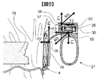
次に、図9にインパクトドライバー21を腰ベルト76に引っ掛けた状態を示す。図9は作業者の動きに伴い、フック4に引き抜き方向の力P2が掛かった時の図を示すものであるが、基端部28と貫通穴50は嵌合しているため腰ベルト76が引っ掛かる支持点26に力P2がかかると基端部28は回動し、基端部28の端点56,56にその中心57の周方向にモーメントM3、M3が働く。そして、モーメントM3、M3は貫通穴50内壁へ垂直に働く力F1、F1と、枢軸30に平行で夫々反対方向に働く力F2、F3とに分解できるが、力F2、F3は相殺されるため、基端部28は貫通穴50内壁へ垂直に働く力F1、F1によって貫通穴50に圧着される。言い換えれば、基端部28は貫通穴50内でこじれ、引き抜けないから、フック4は枢軸30上を指でまっすぐ引き抜く以外引き抜きようがなく、引っ掛かり時の安定性が良い。更に付け加えるとインパクトドライバー21は、ベルト76に引っ掛けられている状態で常に重力が働いているから、引っ掛け片に力P3が働き基端部28が貫通穴50内でこじれている状態が持続する。
Next, FIG. 9 shows a state in which the
更に、インパクトドライバー21を腰ベルト76に引っ掛けた際は、図10(A)に示すように、インパクトドライバー21の重心55がフック4の支持点26の垂下に位置し、引っ掛け片2は腰ベルト76と垂直関係にあり安定している。しかも、図11(B)に示すように木工錐58とドリルチャック59が取付けられたり、図10(C)に示すように電圧の低い軽量電池60が取付けられるとインパクトドライバー21の重心55が夫々重心61,62に変化するが、引っ掛け片2は周方向の複数位置で保持されるため、引っ掛け片2の位置2eを夫々位置2d、2fに簡単に回動させれば、引っ掛け片2と腰ベルト76の関係は常に垂直で深く引っ掛かっている関係にあるため、引っ掛かり時の安定性は部品を追加変更した場合も良い。加えて上述したようにフック4は回動方向に力を加えても強固に回動不能で、更にフック4が作業者の動きに伴い引き抜かれることはないから、併せて引っ掛かり時の安定性が保たれる。
Further, when the
次に、インパクトドライバー21を落下させた場合のフック4の強度に関して述べる。引っ掛け片2が図3に示した位置2aにあればバッテリー18が衝撃を吸収し、位置2c、2d、2e、2fにあれば引っ掛け片2がハンドル9まで湾曲当接しハンドル9が衝撃を吸収する。しかし、引っ掛け片2が位置2a、2c、2d、2e、2f以外にある場合、例えば、位置2gで落下衝撃を受けた場合、引っ掛け片2自身で衝撃を吸収しなければならず、おのずと引っ掛け片2が大型化してしまうという問題があった。従って、図7に示すように基端部28に回転抑止板39を、保持部20に回転抑止板受け52をそれぞれ設け、引っ掛け片2の回転移動範囲を前記した位置2a、2c、2d、2e、2fの範囲に制御し、フック4をコンパクトにすることができる。
Next, the strength of the
以上説明したフックの構成は、複数の位置選択をスライドして回すだけの簡単な方法であり、且つベルト等に引っ掛けた時の安定性が良く、又コンパクトな構造で携帯用工具に隣接する方法で収納可能であるため、例示したインパクトドライバーに限らず、ハウジング内に空きスペースが無い場合や、フックの取付け場所が限定される場合が多い、丸のこ、ドリル、ディスクグラインダ、ドライバー、ハンマ、ジグソー、カッタ、セーバソー、エアツール、釘打ち機等の殆どの携帯用工具に幅広く適用でき汎用性が高い。例えば、図11に示すように、屋根の梁63に引っ掛けるためのフックを丸のこ64に装着する場合であっても、保持部20をモーターハウジング19側面に突設させ引っ掛け片2をコの字形にしモーターハウジング19端面にフック4のスライド量分隙間をあけた状態で隣接する構成にすれば、電気丸のこにも装着可能であり、又、モーター上部に空きスペースが有る図12に示すドリル65若しくはスクリュードライバーに装着する場合であれば、引っ掛け片2を枢軸と平行に突出したL字形にし、フック4及び保持部20全体を収納する構成にでき、装着可能である。図12(C)は図12(B)のD−D断面であるが、このように金型構造上、リングギヤ部47の一部を省いてしまっても構わない。また、上述したように、丸のことドリルどちらにおいても梁やベルト等への引っ掛け時に引っ掛け片2に重力P4が働くが、フック4が保持部20の端面53に抜け止めされ安定しており、更に梁やベルト等から引っ掛け片2を引き抜く時に摩擦によって引っ掛け片2に力P5が働くが、保持部20内でフック4の基端部28がこじれるためフック4がスライドしてしまい抜き辛くなることがなく操作性が良い。
The hook configuration described above is a simple method in which a plurality of position selections are simply slid and turned, and has good stability when hooked on a belt or the like, and a method of adjoining a portable tool with a compact structure. Because it can be stored in, it is not limited to the exemplified impact driver, there are many cases where there is no empty space in the housing or where the hook mounting location is limited, circular saw, drill, disc grinder, screwdriver, hammer, It can be widely applied to most portable tools such as jigsaws, cutters, saversaws, air tools, nailing machines, etc., and is highly versatile. For example, as shown in FIG. 11, even when a hook for hooking on a
また、図4に示す形態のように、フック4に基端部28を設けハウジング1に保持部20を設けたが、図13に示すようにフック4に保持部20を設けハウジング1に基端部28を設ける構成であっても同等の効果が得られる。更に、図14に示すように、図13の基端部28を含むハウジング1と抜け止め部29を入れ替えた構成でも良く、しかも図13のフック4回動時に回転筒32の回転を支持する回転支持穴46を省き図14に示すようにリングギヤ部47によって回転筒32を支持しても良い。このように部分が入れ代わったり、部分を細分化して動作精度を上げたり、1部分で2つの効果を兼用したりする構成でも構わない。
4, the
次にビット収納構成及びその方法について説明する。図1はフックを備えるインパクトドライバーの部分説明図であり、フック4の引っ掛け片2には、溝状の収容保持部であるビット収納部66が凹設され、そのビット収納部66に六面体であるビット11が略完全に収納される。67はビット11が嵌合可能な嵌着部、68はビット11の前後に埋設された首部、69は弾性の平板70から突接され首部を弾性係止可能なストッパ、71はビット収納部1の一部側壁が切り欠かれた切り欠き、72,73はビット11の頭部、74は平板70裏面の凹部である。
Next, the bit storage configuration and method will be described. FIG. 1 is a partial explanatory view of an impact driver provided with a hook, and a hook
一方、ビット11を装着する際は、図15に示すようにビット11をビット収納部66後方(図の右側)からビット軸75方向に頭部73を指で押して摺動させれば、嵌着部67に嵌合すると共に、ビット11の首部68にストッパ69が弾性係止し、ビット11がフック4と組み付けられる。更に図4はビット11がフック4に収納された状態を表す図であり、図4(B)は図4(A)のE−E断面図であるが、六面体であるビット11の三面が嵌着部67に嵌合状態に保持され、ビット11はビット軸75の周方向と半径方向の揺動が防止される。加えて首部68にストッパ69が弾性係止されビット軸75の軸方向の揺動が防止されるため、併せて安定性が良い。また、ビット11が、引っ掛け片2の縁部と面位置に収納されるため、即ちビット11の外周がビット収納部66か突出しないよう完全に埋設するため、ビット11を衣服等に引っ掛けてしまい離脱させる危険性がなく、安全性に優れている。次に図15に示すようにビット11を引き出す時は、ビット収納部66の切り欠き71から指を差し込み頭部72を後方(図の右側)に摺動させれば、ストッパ69若しくは平板70が頭部72によって押圧され平板70が湾曲しストッパ69による係止が解かれると共に、頭部73をビット収納部66から後方へ突出させることができ、その頭部73を指で挟んで引き出せば、ビット11がフック4から引き出される。この時、凹部74によって平板70の弾性圧力を低くしており、しかも引っ掛け片2がバッテリー18側面に当接状態であっても、湾曲した平板70とバッテリー18側面とがぶつからない。
On the other hand, when the
よって上述したように、フックとビット収納部を備える携帯用工具において、フックの引っ掛け片をビット収納部に置き換えればスペース効率が良い。更にビットをビット軸方向に摺動させて着脱する方法で、且つビット軸周方向及び半径方向の揺動を防止する係止手段とビット軸方向の揺動を防止する弾性係止手段とに分けることによって、フックの樹脂一体成形が可能であり、コストと組付け手間がかからない。 Therefore, as described above, in a portable tool including a hook and a bit storage part, space efficiency is good if the hook hook piece is replaced with a bit storage part. Further, the bit is slid in and removed from the bit axis direction, and is divided into locking means for preventing bit axis circumferential and radial swings and elastic locking means for preventing bit axis swings. As a result, the hook can be integrally molded with resin, and the cost and assembly work are not required.
更に、図16に示すように引っ掛け片4の縁部の1部に、滑り止め用または部材保護用のゴム等の軟性体3〜3を圧入、または接着、或いは2層成形すれば、ビット収納部を備えるフックに軟質材を設けることが可能になる。なお、軟質塗料を塗布する方法でも構わない。
Further, as shown in FIG. 16, if a
以上のことからビット収納の構成は、スペース効率が良く、コストと組付け手間が掛からない樹脂一体成形の係止手段を用いているため、例示したインパクトドライバーに限らず、ビットを使用する丸のこ、スクリュードライバー、ドライバードリル、エアツールのドライバー等の携帯用工具に幅広く適用することができる。 From the above, the bit storage configuration is space efficient and uses a resin-integrated locking means that does not require cost and assembly work. It can be widely applied to portable tools such as screwdrivers, screwdriver drills, and pneumatic tool drivers.
1aはハウジング、1bはハウジング、2は引っ掛け片、4はフック、11はビット、18はバッテリー、20は保持部、21はコードレスインパクトドライバー、27はスプリング、29は抜け止め部、30は枢軸、31はギヤ部、32は回転筒、35はナット収納部、36はボルト穴、38は段差、39は回転抑止片、44はボルト、45はナット、46は回転支持穴、47はリングギヤ部、48はスプリング受け、49はスプリング室、50は貫通穴、52は回転抑止片受け、53は端面、54は滑り止め、66はビット収納部、67はかん着部、68は首部、69はストッパ、70は平板、71は切り欠き、72,73は頭部、75はビット軸である。
1a is housing, 1b is housing, 2 is hook piece, 4 is hook, 11 is bit, 18 is battery, 20 is holding part, 21 is cordless impact driver, 27 is spring, 29 is retaining part, 30 is pivot, 31 is a gear part, 32 is a rotating cylinder, 35 is a nut storage part, 36 is a bolt hole, 38 is a step, 39 is a rotation restraining piece, 44 is a bolt, 45 is a nut, 46 is a rotation support hole, 47 is a ring gear part, 48 is a spring receiver, 49 is a spring chamber, 50 is a through hole, 52 is a rotation restraint piece receiver, 53 is an end face, 54 is a slip stopper, 66 is a bit storage part, 67 is a clamping part, 68 is a neck part, and 69 is a stopper. , 70 is a flat plate, 71 is a notch, 72 and 73 are heads, and 75 is a bit shaft.
Claims (3)
該本体胴体部から下方に延びるハンドル部と、
該ハンドル部に設けられたフック部と、
バッテリーとよりなり、
前記本体胴体部には前方に先端工具保持部を収納し、
後方に先端工具に伝達する回転動カを発生するモータを収納し、
前記本体胴体部と反対側の前記ハンドル部には前記モータを駆動するためのバッテリーを装着可能に構成し、
前記フック部は、穴部を有し且つ前記バッテリーを収納した側のハンドル部から延在する保持部と、引っ掛け片と、該引っ掛け片の一端に連設される基端部とよりなり、
前記基端部は円筒状部と、該円筒状部に形成した第1の凹凸部を有し、
前記保持部は前記穴部に前記第1の凹凸部と係合する第2の凹凸部を有し、
前記1及び2の凹凸部を、前記引っ掛け片の先端が前方を向く第1の位置で係合可能にすると共に、
係合を解除して前記引っ掛け片の先端が第1の位置より上方を向く第2の位置に移動して再び前記第1及び第2の凹凸部を係合可能に構成した携帯用工具において、
前記第1の位置は、前記引っ掛け片が前記バッテリーに近接した前記引っ掛け片の収納位置であり、前記第2の位置は、前記ハンドル部と前記引っ掛け片の間に隙間ができ、前記引っ掛け片をベルトへ引っ掛ける位置であることを特徴とする携帯用工具。 The body torso,
A handle portion extending downward from the main body body portion;
A hook portion provided on the handle portion;
Battery and more
In the main body body portion, a tip tool holding portion is housed in the front,
Stores the motor that generates the rotational motion that is transmitted to the tip tool in the rear,
A battery for driving the motor can be attached to the handle on the side opposite to the main body body,
The hook part includes a holding part that has a hole and extends from the handle part on the side where the battery is accommodated, a hook piece, and a base end part that is connected to one end of the hook piece,
The base end portion has a cylindrical portion and a first uneven portion formed in the cylindrical portion,
The holding portion has a second concavo-convex portion that engages with the first uneven portion in the hole,
The concavo-convex portions of 1 and 2 can be engaged at a first position where the front end of the hook piece faces forward,
In the portable tool configured to be disengaged and the first and second concavo-convex parts can be engaged again by moving the tip of the hook piece to the second position facing upward from the first position.
The first position is a storage position of the hook piece that is close to the battery, and the second position is a gap between the handle portion and the hook piece, and the hook piece is A portable tool characterized by being in a position to be hooked on a belt.
Priority Applications (1)
| Application Number | Priority Date | Filing Date | Title |
|---|---|---|---|
| JP2005206352A JP3856040B2 (en) | 2005-07-15 | 2005-07-15 | Portable tools |
Applications Claiming Priority (1)
| Application Number | Priority Date | Filing Date | Title |
|---|---|---|---|
| JP2005206352A JP3856040B2 (en) | 2005-07-15 | 2005-07-15 | Portable tools |
Related Parent Applications (1)
| Application Number | Title | Priority Date | Filing Date |
|---|---|---|---|
| JP2003403877A Division JP4649834B2 (en) | 2003-12-03 | 2003-12-03 | Portable tools |
Publications (3)
| Publication Number | Publication Date |
|---|---|
| JP2005297191A JP2005297191A (en) | 2005-10-27 |
| JP2005297191A5 JP2005297191A5 (en) | 2006-05-18 |
| JP3856040B2 true JP3856040B2 (en) | 2006-12-13 |
Family
ID=35329344
Family Applications (1)
| Application Number | Title | Priority Date | Filing Date |
|---|---|---|---|
| JP2005206352A Expired - Lifetime JP3856040B2 (en) | 2005-07-15 | 2005-07-15 | Portable tools |
Country Status (1)
| Country | Link |
|---|---|
| JP (1) | JP3856040B2 (en) |
Families Citing this family (1)
| Publication number | Priority date | Publication date | Assignee | Title |
|---|---|---|---|---|
| JP7166792B2 (en) * | 2018-02-27 | 2022-11-08 | 株式会社マキタ | portable cutting machine |
Family Cites Families (15)
| Publication number | Priority date | Publication date | Assignee | Title |
|---|---|---|---|---|
| JPS6031910Y2 (en) * | 1980-12-26 | 1985-09-24 | 三菱電機株式会社 | Hanging ring for portable power tools |
| JPS60165866U (en) * | 1984-04-11 | 1985-11-02 | 岩崎通信機株式会社 | portable electrical equipment |
| JPS624065U (en) * | 1985-06-25 | 1987-01-12 | ||
| JPS63120784U (en) * | 1987-01-26 | 1988-08-04 | ||
| JP2506708Y2 (en) * | 1990-11-30 | 1996-08-14 | 日立工機株式会社 | Electric tool hook mounting structure |
| JP2569670Y2 (en) * | 1992-01-27 | 1998-04-28 | リョービ株式会社 | Electric tool |
| JPH0850265A (en) * | 1994-08-05 | 1996-02-20 | Nojiri Megane Kogyo Kk | Temple angle adjusting mechanism of spectacle frame |
| JPH08252784A (en) * | 1995-03-15 | 1996-10-01 | Makita Corp | Hook of portable tool |
| JPH09230063A (en) * | 1996-02-21 | 1997-09-05 | Maeda Corp | Ceiling-installed apparatus |
| JPH10327938A (en) * | 1997-05-29 | 1998-12-15 | Yagiken:Kk | Angle adjusting device for folding |
| JP3630946B2 (en) * | 1997-10-30 | 2005-03-23 | 株式会社マキタ | Portable tool hook |
| JP3758338B2 (en) * | 1997-11-07 | 2006-03-22 | 日立工機株式会社 | Battery tools |
| JP2000300140A (en) * | 1999-04-23 | 2000-10-31 | Zaitetsu Kin | Angle adjusting device for fishing rod-supporting tool |
| JP3553589B2 (en) * | 2003-09-29 | 2004-08-11 | 日立工機株式会社 | Portable tools |
| JP4649834B2 (en) * | 2003-12-03 | 2011-03-16 | 日立工機株式会社 | Portable tools |
-
2005
- 2005-07-15 JP JP2005206352A patent/JP3856040B2/en not_active Expired - Lifetime
Also Published As
| Publication number | Publication date |
|---|---|
| JP2005297191A (en) | 2005-10-27 |
Similar Documents
| Publication | Publication Date | Title |
|---|---|---|
| JP3553585B2 (en) | Electric tool | |
| US7108079B2 (en) | Electric power tool | |
| US6886643B2 (en) | Shaft lock mechanism for a rotary power hand tool | |
| JP3807444B2 (en) | Operation method of portable tools | |
| JP4953170B2 (en) | Electric tool | |
| JP3856040B2 (en) | Portable tools | |
| JP3807445B2 (en) | Portable tools | |
| JP4649834B2 (en) | Portable tools | |
| JP3553589B2 (en) | Portable tools | |
| JP3767494B2 (en) | Electric tool | |
| JP4399866B2 (en) | Electric tool | |
| JP3553587B2 (en) | Portable tools | |
| JP3553588B2 (en) | Portable tools | |
| JP2004090217A (en) | Portable tool | |
| JP4000998B2 (en) | Portable tools | |
| JP2005313322A (en) | Power tool | |
| JP2008178979A (en) | Power tool | |
| JP4051370B2 (en) | Electric tool | |
| EP1446266A1 (en) | Tool holder for hammer | |
| JP2006055995A (en) | Power tool | |
| JP2018024028A (en) | Locking tool |
Legal Events
| Date | Code | Title | Description |
|---|---|---|---|
| A621 | Written request for application examination |
Free format text: JAPANESE INTERMEDIATE CODE: A621 Effective date: 20050715 |
|
| A521 | Written amendment |
Free format text: JAPANESE INTERMEDIATE CODE: A523 Effective date: 20060314 |
|
| A871 | Explanation of circumstances concerning accelerated examination |
Free format text: JAPANESE INTERMEDIATE CODE: A871 Effective date: 20060314 |
|
| A975 | Report on accelerated examination |
Free format text: JAPANESE INTERMEDIATE CODE: A971005 Effective date: 20060420 |
|
| A131 | Notification of reasons for refusal |
Free format text: JAPANESE INTERMEDIATE CODE: A131 Effective date: 20060508 |
|
| A521 | Written amendment |
Free format text: JAPANESE INTERMEDIATE CODE: A523 Effective date: 20060612 |
|
| A131 | Notification of reasons for refusal |
Free format text: JAPANESE INTERMEDIATE CODE: A131 Effective date: 20060718 |
|
| A521 | Written amendment |
Free format text: JAPANESE INTERMEDIATE CODE: A523 Effective date: 20060728 |
|
| TRDD | Decision of grant or rejection written | ||
| A01 | Written decision to grant a patent or to grant a registration (utility model) |
Free format text: JAPANESE INTERMEDIATE CODE: A01 Effective date: 20060822 |
|
| A61 | First payment of annual fees (during grant procedure) |
Free format text: JAPANESE INTERMEDIATE CODE: A61 Effective date: 20060904 |
|
| R150 | Certificate of patent or registration of utility model |
Ref document number: 3856040 Country of ref document: JP Free format text: JAPANESE INTERMEDIATE CODE: R150 Free format text: JAPANESE INTERMEDIATE CODE: R150 |
|
| FPAY | Renewal fee payment (event date is renewal date of database) |
Free format text: PAYMENT UNTIL: 20090922 Year of fee payment: 3 |
|
| FPAY | Renewal fee payment (event date is renewal date of database) |
Free format text: PAYMENT UNTIL: 20100922 Year of fee payment: 4 |
|
| FPAY | Renewal fee payment (event date is renewal date of database) |
Free format text: PAYMENT UNTIL: 20210922 Year of fee payment: 15 |
|
| R250 | Receipt of annual fees |
Free format text: JAPANESE INTERMEDIATE CODE: R250 |
|
| S533 | Written request for registration of change of name |
Free format text: JAPANESE INTERMEDIATE CODE: R313533 |
|
| R350 | Written notification of registration of transfer |
Free format text: JAPANESE INTERMEDIATE CODE: R350 |
|
| EXPY | Cancellation because of completion of term |