JP3855397B2 - Opening device in loom - Google Patents
Opening device in loom Download PDFInfo
- Publication number
- JP3855397B2 JP3855397B2 JP27293297A JP27293297A JP3855397B2 JP 3855397 B2 JP3855397 B2 JP 3855397B2 JP 27293297 A JP27293297 A JP 27293297A JP 27293297 A JP27293297 A JP 27293297A JP 3855397 B2 JP3855397 B2 JP 3855397B2
- Authority
- JP
- Japan
- Prior art keywords
- holder
- transmission member
- frame
- pair
- holders
- Prior art date
- Legal status (The legal status is an assumption and is not a legal conclusion. Google has not performed a legal analysis and makes no representation as to the accuracy of the status listed.)
- Expired - Fee Related
Links
Images


Landscapes
- Transmission Devices (AREA)
- Looms (AREA)
Description
【0001】
【発明の属する技術分野】
本発明は、往復駆動機構の作動によって綜絖枠を上下動する開口装置に関するものである。
【0002】
【従来の技術】
綜絖枠を上下動する開口装置が特開昭64−20347号公報、特開平4−240239号公報、特開平9−21030号公報に開示されている。
【0003】
特開昭64−20347号公報の装置では、往復駆動機構の作動によって上下動される伝達要素が環状の雄部材の環内でジョーと雄部材との間に挟み付けられ、雄部材が綜絖枠に固定された雌部材に嵌合されている。伝達要素の上下動は、雄部材及び雌部材を介して綜絖枠に伝達される。伝達要素に対するジョーと雄部材との締め付けを緩めれば、伝達要素に対する雌部材の取り付け位置、即ち綜絖枠の高さ位置を調整することができる。
【0004】
特開平4−240239号公報の装置では、上下動される伝達部材に連結されたねじ状の口金に円筒スリーブが螺着されており、円筒スリーブの環状肩部に側板が嵌合して掛け止められている。円筒スリーブはロックナットの締め付けによって口金に固定される。側板は綜絖枠の上部縦材に固定されている。伝達部材の上下動は、円筒スリーブ及び側板を介して綜絖枠に伝達される。口金に対する円筒スリーブの螺着位置を調整すれば、伝達部材に対する側板の取り付け位置、即ち綜絖枠の高さ位置を調整することができる。
【0005】
特開平9−21030号公報の装置では、上下動されるロッド部材のねじ部がエリメントに遊嵌されており、エリメントが前記ねじ部に螺合された上下一対のナットによって挟み込み固定されている。エリメント及び綜絖枠の枠体は環状のクランパによって締め付け固定されている。ロッド部材の上下動は、一対のナット及びエリメントを介して綜絖枠に伝達される。ねじ部に対する一対のナットの螺着位置を調整すれば、ロッド部材に対するエリメントの取り付け位置、即ち綜絖枠の高さ位置を調整することができる。
【0006】
【発明が解決しようとする課題】
しかし、特開昭64−20347号公報の装置では、雄部材と雌部材との嵌合部にガタがあると、綜絖枠の高速の上下動に伴う荷重によって前記嵌合部で異常音が発生したり、損傷が起きたりする。
【0007】
特開平4−240239号公報の装置においても、環状肩部と側板との嵌合部にガタがあると、綜絖枠の高速の上下動に伴う荷重によって前記嵌合部で異常音が発生したり、損傷が起きたりする。又、綜絖枠の高速の上下動に伴う荷重が円筒スリーブと口金との螺合部及びロックナットと口金との螺合部に集中し、口金、円筒スリーブあるいはロックナットが損傷する。
【0008】
特開平9−21030号公報の装置では、綜絖枠の高速の上下動に伴う荷重が一対のナットとねじ部との螺合部に集中し、ナットあるいはねじ部が損傷し易い。又、ロッド部材を挿通するエリメントを環状のクランパが包囲するため、織機の前後方向におけるクランパの厚みが大きくなる。クランパの厚みが大きくなると、織機の前後方向に配列された綜絖枠の配列ピッチが大きくなり、後側の綜絖枠ほど上下動のストロークが大きくなる。綜絖枠の上下動のストロークが大きくなると、織機の高速運転が難しくなる。
【0009】
本発明は、往復動される伝達部材と綜絖枠との固定手段が損傷しにくく、かつ綜絖枠の配列ピッチを小さくできるようにすることを目的する。
【0010】
【課題を解決するための手段】
そのために本発明は、往復駆動機構の作動によって往復動される伝達部材と綜絖枠とを着脱可能に固定する固定手段を備え、前記往復駆動機構の作動によって綜絖枠を上下動する開口装置を対象とし、請求項1の発明では、前記伝達部材に圧接される第1のホルダと、前記伝達部材を挟んで第1のホルダに対向して前記伝達部材に圧接される第2のホルダと、前記一対のホルダを前記伝達部材に圧接すると共に、前記伝達部材と前記綜絖枠との間に前記第1のホルダを挟み込む圧接手段と、前記圧接手段の圧接作用を解除した状態にて前記一対のホルダを脱落しないように前記伝達部材に係合する係合手段と、前記圧接手段の圧接作用を解除した状態にて前記一対のホルダと前記伝達部材との相対位置を変更する相対位置変更手段とを備えた前記固定手段を構成し、前記相対位置変更手段は、前記伝達部材に設けられたねじ部と、前記ねじ部に螺合する高さ位置調整ナットとを備え、前記一対のホルダのうちの少なくとも前記第1のホルダが前記高さ位置調整ナットに追随移動可能に係合されている。
【0011】
前記圧接手段の圧接作用により一対のホルダが伝達部材を挟み込む。伝達部材の往復動は、一対のホルダを介して綜絖枠に伝達される。綜絖枠の高速の往復動に伴う荷重は、圧接関係にある部材間の圧接部に掛かるため、前記荷重による部材の損傷は生じにくい。また、第1のホルダは高さ位置調整ナットの螺合移動に追随し、綜絖枠の高さ位置は高さ位置調整ナットの螺合移動によって調整される。
【0012】
請求項2の発明では、前記綜絖枠と前記伝達部材とを包囲するクランプ輪と、前記クランプ輪に貫通螺着されて前記第2のホルダに当接するねじとを備えた圧接手段を構成した。
【0013】
ねじの締め付けにによって一対のホルダが伝達部材に圧接される。
【0014】
請求項3の発明では、前記第1のホルダを前記綜絖枠に掛け止める掛け止め手段と、第1のホルダ及び第2のホルダを前記伝達部材に束ね合わせる束ね合わせ手段とを備えた前記係合手段を構成した。
【0015】
伝達部材に束ね合わせられた一対のホルダが伝達部材から脱落することはない。
【0016】
【発明の実施の形態】
以下、本発明を具体化した第1の実施の形態を図1〜図3に基づいて説明する。
【0017】
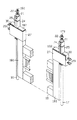
図1に示すように、織機の左右のサイドフレーム11,12の内側にはスイングレバー13,14が回動可能に支持されている。スイングレバー13は図示しない往復駆動機構によって往復揺動される。スイングレバー13の揺動は伝達ロッド15を介してスイングレバー14に伝達され、両スイングレバー13,14が同期揺動する。スイングレバー13,14にはリンク31が連結されており、リンク31には垂直ロッド16,17が垂立状態に取り付けられている。スイングレバー13,14の揺動は垂直ロッド16,17の上下動に変換され、垂直ロッド16,17の上下動はガイド19,20によって案内される。垂直ロッド16,17間には綜絖枠18が架設支持されている。綜絖枠18は垂直ロッド16,17と一体的に上下動する。
【0018】
垂直ロッド16,17の上端部にはねじ部161,171が形成されている。ねじ部161には高さ位置調整ナット21及びロックナット22が螺着されている。ロックナット22の締め付けによって高さ位置調整ナット21がねじ部161に固定される。高さ位置調整ナット21の上下の中間部には環状の係止溝211が形成されている。
【0019】
綜絖枠18の縦枠181の上端部の連結部182には掛け止めピン23が圧入されており、掛け止めピン23には第1のホルダ24が掛け止められている。垂直ロッド16を挟んで第1のホルダ24とは反対側には第2のホルダ25が第1のホルダ24と対向して配置されている。第1のホルダ24及び第2のホルダ25は一対の弾性リング26によって垂直ロッド16に束ね合わされている。図2に示すように、第1のホルダ24及び第2のホルダ25の対向面には把持凹部241,251が形成されている。把持凹部241,251は垂直ロッド16のねじ部161の下位の周面に接合する。第1のホルダ24及び第2のホルダ25の上端部には係止突部242,252が形成されている。係止突部242,252は係止溝211に係止されている。
【0020】
連結部182、垂直ロッド16及び一対のホルダ24,25は四角環状のクランプ輪27によって包囲されている。クランプ輪27は連結部182に止着されている。クランプ輪27の内面には雌ねじ体28が止着されている。クランプ輪27の一部となる雌ねじ体28には一対のねじ孔281が形成されており、一対のねじ29がクランプ輪27の外面からねじ孔281に螺合されている。ねじ29は第2のホルダ25に向いており、ねじ29の先端と第2のホルダ25との間には板30が介在されている。連結部182、一対のホルダ24,25、垂直ロッド16及び板30はねじ29の締め付けによりクランプ輪27内で互いに固定される。即ち、第1のホルダ24及び第2のホルダ25は、把持凹部241,151を介して垂直ロッド16に圧接され、第1のホルダ24は連結部182に圧接される。板30はねじ29と第2のホルダ25との直接接触を阻止して第2のホルダ25の損傷を防止する。
【0021】
垂直ロッド16の上下動は、ホルダ24,25及び連結部182を介して綜絖枠18に伝達される。ねじ29の締め付けを緩めると、第1のホルダ24及び第2のホルダ25は垂直ロッド16に対して上下に移動可能となる。ねじ29の締め付けを緩めた状態においても、第2のホルダ25が弾性リング26によって垂直ロッド16に束ね合わせられているため、第2のホルダ25が脱落することはない。ロックナット22の締め付けを緩めて高さ位置調整ナット21を螺合移動すれば、ホルダ24,25が高さ位置調整ナット21の螺合移動に追随する。図3は、ねじ29及びロックナット22の締め付けを緩めた状態を示す。
【0022】
ねじ29の先端を雌ねじ体28のねじ孔281内に引っ込ませれば、第1のホルダ24を掛け止めピン23から外すことができ、綜絖枠18と共にクランプ輪27を垂直ロッド16の上端から上方へ外すことができる。この状態においても一対のホルダ24,25は弾性リング26によって垂直ロッド16に束ね合わせ把持される。
【0023】
クランプ輪27、雌ねじ体28及びねじ29からなる圧接手段、掛け止め手段となる掛け止めピン23及び束ね合わせ手段となる一対の弾性リング26からなる係合手段、ねじ部161、高さ位置調整ナット21及び係止突部242,252からなる相対位置変更手段と同様の機構が垂直ロッド17側にも設けられている。
【0024】
第1の実施の形態では以下の効果が得られる。
(1-1)伝達部材である垂直ロッド16,17の往復動は、垂直ロッド16,17を挟み込む一対のホルダ24,25を介して綜絖枠18に伝達される。綜絖枠18の高速の上下動に伴う荷重は、連結部182と第1のホルダ24との間、垂直ロッド16,17とホルダ16,17との間という圧接関係にある部材間の圧接部に掛かり、前記荷重が高さ位置調整ナット21とねじ部161,171との螺合部に掛かることはない。従って、前記荷重による部材の損傷は生じにくい。(1-2)第1のホルダ24及び第2のホルダ25は垂直ロッド16,17を挟んで対向しており、垂直ロッド16,17の周囲全体を包囲してはいない。従って、図2に示すように、ホルダ24,25の幅Hを垂直ロッド16,17の径Dと同じにすることができ、クランプ輪27の内側の厚みT1を垂直ロッド16,17の径Dと同じにすることができる。即ち、クランプ輪27の外側の厚みT2を垂直ロッド16,17の径Dに応じて最小にすることができる。クランプ輪27の厚みT2の低減は、複数枚の綜絖枠18の配列ピッチの低減をもたらす。
(1-3)第1のホルダ24及び第2のホルダ25は、高さ位置調整ナット21の螺合移動に対して係止溝211と係止突部242,252との係合を介して追随する。ホルダ24,25は、綜絖枠18の高さ位置を調整するための高さ位置調整ナット21の螺合移動に追随すればよいだけであるため、係止溝211と係止突部242,252との嵌合精度は問題にならない。
(1-4)ねじ29及びクランプ輪27からなる圧接手段は、一対のホルダ24,25を垂直ロッド16,17に圧接すると共に、第1のホルダ24を連結部182に圧接する手段として簡便である。
(1-5)ねじ部161,171、高さ位置調整ナット21及び一対のホルダ24,25からなる相対位置変更手段は簡便である。
【0025】
本発明では、図4に示すように、第1のホルダ183を連結部182に一体形成した第2の実施の形態、あるいは図5に示すように、第2のホルダ32を係止溝211に係止しないようにした第3の実施の形態も可能である。
【0026】
【発明の効果】
以上詳述したように本発明では、対向する一対のホルダによって伝達部材を挟み込むと共に、伝達部材と綜絖枠との間に一方のホルダを挟み込むようにしたので、伝達部材と綜絖枠との固定手段が損傷しにくく、かつ綜絖枠の配列ピッチを小さくできるという優れた効果を奏する。
【図面の簡単な説明】
【図1】第1の実施の形態を示し、要部拡大断面図を組み込んだ正面図。
【図2】要部分解斜視図。
【図3】一部破断斜視図。
【図4】第2の実施の形態を示す要部拡大断面図。
【図5】第3の実施の形態を示す要部拡大断面図。
【符号の説明】
16,17…伝達部材となる垂直ロッド、161,171…相対位置変更手段を構成するねじ部、18…綜絖枠、21…相対位置変更手段を構成する高さ位置調整ナット、23…係合手段を構成する掛け止め手段としての掛け止めピン、24…第1のホルダ、25…第2のホルダ、26…係合手段を構成する束ね合わせ手段としての弾性リング、27…圧接手段を構成するクランプ輪、28…圧接手段を構成する雌ねじ体、29…圧接手段を構成するねじ。[0001]
BACKGROUND OF THE INVENTION
The present invention relates to an opening device that moves a frame up and down by operating a reciprocating drive mechanism.
[0002]
[Prior art]
An opening device that moves the frame up and down is disclosed in Japanese Patent Application Laid-Open Nos. 64-20347, 4-240239, and 9-21030.
[0003]
In the device disclosed in Japanese Patent Application Laid-Open No. 64-20347, a transmission element that is moved up and down by the operation of a reciprocating drive mechanism is sandwiched between a jaw and a male member in the ring of an annular male member, and the male member is a frame. It is fitted to the female member fixed to. The vertical movement of the transmission element is transmitted to the collar frame via the male member and the female member. If the tightening of the jaw and the male member with respect to the transmission element is loosened, the attachment position of the female member with respect to the transmission element, that is, the height position of the collar frame can be adjusted.
[0004]
In the device disclosed in Japanese Patent Laid-Open No. 4-240239, a cylindrical sleeve is screwed to a screw-shaped base connected to a transmission member that is moved up and down, and a side plate is fitted to an annular shoulder portion of the cylindrical sleeve and latched. It has been. The cylindrical sleeve is fixed to the base by tightening a lock nut. The side plate is fixed to the upper vertical member of the frame. The vertical movement of the transmission member is transmitted to the frame through the cylindrical sleeve and the side plate. By adjusting the screwing position of the cylindrical sleeve with respect to the base, the attachment position of the side plate with respect to the transmission member, that is, the height position of the collar frame can be adjusted.
[0005]
In the device disclosed in Japanese Patent Application Laid-Open No. 9-21030, a threaded portion of a rod member that is moved up and down is loosely fitted to an element, and the element is sandwiched and fixed by a pair of upper and lower nuts screwed into the threaded part. The frame body of the element and the saddle frame is fastened and fixed by an annular clamper. The vertical movement of the rod member is transmitted to the collar frame via a pair of nuts and elements. By adjusting the screwing position of the pair of nuts with respect to the threaded portion, the attachment position of the element with respect to the rod member, that is, the height position of the collar frame can be adjusted.
[0006]
[Problems to be solved by the invention]
However, in the device disclosed in Japanese Patent Application Laid-Open No. 64-20347, if there is play in the fitting portion between the male member and the female member, abnormal noise is generated in the fitting portion due to the load accompanying the high-speed vertical movement of the collar frame. Or damage may occur.
[0007]
Even in the device disclosed in Japanese Patent Laid-Open No. 4-240239, if there is a backlash in the fitting portion between the annular shoulder portion and the side plate, abnormal noise may be generated in the fitting portion due to the load accompanying the high-speed vertical movement of the collar frame. Damage may occur. In addition, the load accompanying the vertical movement of the flange frame at high speed concentrates on the threaded portion between the cylindrical sleeve and the base and the threaded portion between the lock nut and the base, and the base, the cylindrical sleeve, or the lock nut is damaged.
[0008]
In the apparatus disclosed in Japanese Patent Laid-Open No. 9-21030, the load accompanying the high-speed vertical movement of the flange frame concentrates on the screwed portion between the pair of nuts and the screw portion, and the nut or the screw portion is easily damaged. Further, since the annular clamper surrounds the element through which the rod member is inserted, the thickness of the clamper in the longitudinal direction of the loom increases. When the thickness of the clamper increases, the arrangement pitch of the eaves frames arranged in the front-rear direction of the loom increases, and the vertical stroke of the rear eaves frame increases. If the stroke of the vertical movement of the cocoon frame becomes large, high-speed operation of the loom becomes difficult.
[0009]
An object of the present invention is to make it difficult to damage the fixing means between the reciprocating transmission member and the eaves frame and to reduce the arrangement pitch of the eaves frame.
[0010]
[Means for Solving the Problems]
To this end, the present invention is directed to an opening device that includes a fixing means for detachably fixing a transmission member that is reciprocated by the operation of the reciprocating drive mechanism and the collar frame, and that moves the collar frame up and down by the operation of the reciprocating drive mechanism. In the invention of
[0011]
The pair of holders sandwich the transmission member by the pressure contact action of the pressure contact means. The reciprocating motion of the transmission member is transmitted to the collar frame via a pair of holders. Since the load accompanying the high-speed reciprocation of the saddle frame is applied to the pressure contact portion between the members in the pressure contact relationship, the member is not easily damaged by the load. The first holder follows the screwing movement of the height position adjusting nut, and the height position of the collar frame is adjusted by the screwing movement of the height position adjusting nut.
[0012]
According to a second aspect of the present invention, there is provided pressure contact means including a clamp ring that surrounds the collar frame and the transmission member, and a screw that is threaded through the clamp ring and abuts against the second holder.
[0013]
The pair of holders are pressed against the transmission member by tightening the screws .
[0014]
In the invention 請 Motomeko 3, the engagement with the latching means for hooking said first holder to said heald frame, and a bundling alignment means to align bundled first holder and the second holder to the transmission member Combined means were configured.
[0015]
The pair of holders bundled together with the transmission member does not fall off the transmission member.
[0016]
DETAILED DESCRIPTION OF THE INVENTION
Hereinafter, a first embodiment of the present invention will be described with reference to FIGS.
[0017]
As shown in FIG. 1,
[0018]
Screw
[0019]
A
[0020]
The connecting
[0021]
The vertical movement of the
[0022]
If the tip of the
[0023]
[0024]
The following effects can be obtained in the first embodiment.
(1-1) The reciprocating motion of the
(1-3) The
(1-4) The pressure contact means including the
(1-5) The relative position changing means including the
[0025]
In the present invention, as shown in FIG. 4, the second embodiment in which the
[0026]
【The invention's effect】
As described above in detail, in the present invention, the transmission member is sandwiched between the pair of opposed holders, and one holder is sandwiched between the transmission member and the collar frame, so that the fixing means for the transmission member and the collar frame is fixed. Is advantageous in that it is difficult to damage and the arrangement pitch of the frame can be reduced.
[Brief description of the drawings]
FIG. 1 is a front view showing a first embodiment and incorporating an enlarged sectional view of a main part.
FIG. 2 is an exploded perspective view of a main part.
FIG. 3 is a partially broken perspective view.
FIG. 4 is an enlarged cross-sectional view of a main part showing a second embodiment.
FIG. 5 is an enlarged cross-sectional view of a main part showing a third embodiment.
[Explanation of symbols]
16, 17, a vertical rod serving as a transmission member, 161, 171, a screw portion constituting a relative position changing means, 18, a flange frame, 21, a height position adjusting nut constituting a relative position changing means, 23, engaging means Latching pins as latching means, 24 ... first holder, 25 ... second holder, 26 ... elastic ring as bundling means constituting engagement means, 27 ... clamp constituting pressure contact means Rings, 28 ... female screw bodies constituting the pressure contact means, 29 ... screws constituting the pressure contact means.
Claims (3)
前記伝達部材に圧接される第1のホルダと、
前記伝達部材を挟んで第1のホルダに対向して前記伝達部材に圧接される第2のホルダと、
前記一対のホルダを前記伝達部材に圧接すると共に、前記伝達部材と前記綜絖枠との間に前記第1のホルダを挟み込む圧接手段と、
前記圧接手段の圧接作用を解除した状態にて前記一対のホルダを脱落しないように前記伝達部材に係合する係合手段と、
前記圧接手段の圧接作用を解除した状態にて前記一対のホルダと前記伝達部材との相対位置を変更する相対位置変更手段とを備えた前記固定手段を構成し、前記相対位置変更手段は、前記伝達部材に設けられたねじ部と、前記ねじ部に螺合する高さ位置調整ナットとを備え、前記一対のホルダのうちの少なくとも前記第1のホルダが前記高さ位置調整ナットに追随移動可能に係合されている織機における開口装置。In an opening device that includes a fixing means for detachably fixing a transmission member that is reciprocated by the operation of the reciprocating drive mechanism and the collar frame, and that moves the collar frame up and down by the operation of the reciprocating drive mechanism,
A first holder pressed against the transmission member;
A second holder pressed against the transmission member opposite the first holder across the transmission member;
Pressure contact means for pressing the pair of holders against the transmission member, and sandwiching the first holder between the transmission member and the flange frame;
Engagement means for engaging the transmission member so as not to drop the pair of holders in a state in which the pressure contact action of the pressure contact means is released;
The fixing means includes a relative position changing means for changing a relative position between the pair of holders and the transmission member in a state in which the pressing action of the pressing means is released, and the relative position changing means includes the A screw portion provided on the transmission member; and a height position adjusting nut that is screwed to the screw portion, wherein at least the first holder of the pair of holders is capable of following the height position adjusting nut. Opening device in a loom being engaged with .
Priority Applications (1)
| Application Number | Priority Date | Filing Date | Title |
|---|---|---|---|
| JP27293297A JP3855397B2 (en) | 1997-10-06 | 1997-10-06 | Opening device in loom |
Applications Claiming Priority (1)
| Application Number | Priority Date | Filing Date | Title |
|---|---|---|---|
| JP27293297A JP3855397B2 (en) | 1997-10-06 | 1997-10-06 | Opening device in loom |
Publications (2)
| Publication Number | Publication Date |
|---|---|
| JPH11107103A JPH11107103A (en) | 1999-04-20 |
| JP3855397B2 true JP3855397B2 (en) | 2006-12-06 |
Family
ID=17520782
Family Applications (1)
| Application Number | Title | Priority Date | Filing Date |
|---|---|---|---|
| JP27293297A Expired - Fee Related JP3855397B2 (en) | 1997-10-06 | 1997-10-06 | Opening device in loom |
Country Status (1)
| Country | Link |
|---|---|
| JP (1) | JP3855397B2 (en) |
Cited By (1)
| Publication number | Priority date | Publication date | Assignee | Title |
|---|---|---|---|---|
| CN102864552A (en) * | 2011-07-06 | 2013-01-09 | 株式会社丰田自动织机 | Opening apparatus and control method thereof |
Families Citing this family (3)
| Publication number | Priority date | Publication date | Assignee | Title |
|---|---|---|---|---|
| JP2009293154A (en) | 2008-06-05 | 2009-12-17 | Tsudakoma Corp | Heald-frame height adjusting apparatus |
| JP5629336B2 (en) * | 2013-02-06 | 2014-11-19 | 津田駒工業株式会社 | 綜 絖 Frame height adjustment device |
| JP6530258B2 (en) | 2015-06-29 | 2019-06-12 | 津田駒工業株式会社 | Weir frame height adjustment device for loom |
-
1997
- 1997-10-06 JP JP27293297A patent/JP3855397B2/en not_active Expired - Fee Related
Cited By (2)
| Publication number | Priority date | Publication date | Assignee | Title |
|---|---|---|---|---|
| CN102864552A (en) * | 2011-07-06 | 2013-01-09 | 株式会社丰田自动织机 | Opening apparatus and control method thereof |
| CN102864552B (en) * | 2011-07-06 | 2014-04-16 | 株式会社丰田自动织机 | Opening apparatus and control method thereof |
Also Published As
| Publication number | Publication date |
|---|---|
| JPH11107103A (en) | 1999-04-20 |
Similar Documents
| Publication | Publication Date | Title |
|---|---|---|
| TWI457258B (en) | A locking device for locking together two slidably mounted tubes | |
| US20080274845A1 (en) | Front derailleur for a bicycle | |
| JP3855397B2 (en) | Opening device in loom | |
| US7637734B2 (en) | Stationary platen of injection molding machine | |
| US20050204846A1 (en) | Device for the attachment of a derailleur to a bicycle and derailleur comprising such an attachment device | |
| EP0704371B1 (en) | Bicycle brake device | |
| JP3640427B2 (en) | Bicycle braking operation device | |
| JP2011102063A (en) | Brake for bicycle | |
| JPS6276093U (en) | ||
| JPH03117504A (en) | Tool partial coupling device | |
| JP3470046B2 (en) | Upper die holder device for press brake | |
| FI90304B (en) | Locking device for chair seats | |
| JPH10316386A (en) | Removable clamp pad | |
| JP2971013B2 (en) | Upper die device in bending machine | |
| JP3698777B2 (en) | Clutch release device | |
| JPH067286Y2 (en) | Uneven surface shaping device | |
| US6736243B1 (en) | Mechanical type disc brake for bicycle | |
| KR100535388B1 (en) | A connecting device for a vacuum cup attachment | |
| US5181688A (en) | Mechanism for coupling a component with a vehicle | |
| JP3751363B2 (en) | Optical fiber fixing device for optical fiber connector | |
| JPH10184620A (en) | Toggle clamp | |
| JP2560828Y2 (en) | Cleat locking device unit for bicycle pedal | |
| JP5048744B2 (en) | Bicycle brake | |
| CN100355620C (en) | Coupling member for interconnecting a bicycle steering rod and a bicycle fork rod | |
| JPH023789Y2 (en) |
Legal Events
| Date | Code | Title | Description |
|---|---|---|---|
| A621 | Written request for application examination |
Free format text: JAPANESE INTERMEDIATE CODE: A621 Effective date: 20040526 |
|
| A977 | Report on retrieval |
Free format text: JAPANESE INTERMEDIATE CODE: A971007 Effective date: 20051108 |
|
| A131 | Notification of reasons for refusal |
Free format text: JAPANESE INTERMEDIATE CODE: A131 Effective date: 20051115 |
|
| A521 | Written amendment |
Free format text: JAPANESE INTERMEDIATE CODE: A523 Effective date: 20060110 |
|
| TRDD | Decision of grant or rejection written | ||
| A01 | Written decision to grant a patent or to grant a registration (utility model) |
Free format text: JAPANESE INTERMEDIATE CODE: A01 Effective date: 20060822 |
|
| A61 | First payment of annual fees (during grant procedure) |
Free format text: JAPANESE INTERMEDIATE CODE: A61 Effective date: 20060904 |
|
| FPAY | Renewal fee payment (event date is renewal date of database) |
Free format text: PAYMENT UNTIL: 20120922 Year of fee payment: 6 |
|
| FPAY | Renewal fee payment (event date is renewal date of database) |
Free format text: PAYMENT UNTIL: 20120922 Year of fee payment: 6 |
|
| FPAY | Renewal fee payment (event date is renewal date of database) |
Free format text: PAYMENT UNTIL: 20130922 Year of fee payment: 7 |
|
| R250 | Receipt of annual fees |
Free format text: JAPANESE INTERMEDIATE CODE: R250 |
|
| LAPS | Cancellation because of no payment of annual fees |