JP3852829B2 - Filtration device backwash method and apparatus - Google Patents
Filtration device backwash method and apparatus Download PDFInfo
- Publication number
- JP3852829B2 JP3852829B2 JP2001391626A JP2001391626A JP3852829B2 JP 3852829 B2 JP3852829 B2 JP 3852829B2 JP 2001391626 A JP2001391626 A JP 2001391626A JP 2001391626 A JP2001391626 A JP 2001391626A JP 3852829 B2 JP3852829 B2 JP 3852829B2
- Authority
- JP
- Japan
- Prior art keywords
- water
- backwashing
- filtration
- condensate
- filter
- Prior art date
- Legal status (The legal status is an assumption and is not a legal conclusion. Google has not performed a legal analysis and makes no representation as to the accuracy of the status listed.)
- Expired - Fee Related
Links
Images


Description
【0001】
【発明の属する技術分野】
本発明は、濾過装置の逆洗方法および装置に関し、とくに、加圧水型原子力発電所や火力発電所等の発電プラントの復水処理に用いる濾過装置の逆洗に好適な方法および装置に関する。
【0002】
【従来の技術】
加圧水型原子力発電所や火力発電所等の発電プラントにおいては、例えば用水の処理方法の一つとして、濾過装置により、被処理水中の主に酸化鉄からなる懸濁物質を濾過し、分離濃縮している。濾過操作を継続すると、濾材表面での懸濁物質の捕捉量が増加し、濾過装置の差圧が増加する。濾過装置の差圧とは、濾材がクリーンな状態の初期差圧と濾材外表面に蓄積された懸濁物質により生じる差圧が合計されたものである。濾過装置の差圧が増加すると、通常、純水と空気による逆洗を行い、濾材表面に捕捉されていた懸濁物質を排出し、濾材をクリーンな状態に戻し、濾過装置の差圧を回復させるようにしている。
【0003】
この差圧回復操作の際に排出される逆洗水の簡単な処理方法として、沈降分離タンクで静置しての固液分離がある。この場合、逆洗水中の懸濁物質は沈降し、懸濁物質と上澄み液とに分離可能になり、逆洗水の減容化が図れ、沈降したスラッジは脱水処理をして産業廃棄物として処理することができる。
【0004】
【発明が解決しようとする課題】
ところが、処理される逆洗水中に微細な懸濁物質や粒子が含有されていると、それらは沈降分離タンクにおいて沈降しにくいため固液分離性能が低下する。とくに、近年高性能のプリーツフィルタの使用が検討されているが、プリーツフィルタの特徴として、沈降しにくい極めて微細な粒子まで精度良くフィルタに捕捉される。したがって、逆洗水中の懸濁物質も極めて微細な粒子となるため、沈降分離タンクにおいて懸濁物質の沈降性が悪く、容易に十分な固液分離ができないという問題が生じる。固液分離性能が低下すると、沈降スラッジの脱水処理や上澄水の処理にコストと時間がかかることになる。
【0005】
また、このような問題を防止あるいは軽減するためには、沈降分離タンクあるいはそれに逆洗水を導入する経路に、沈降剤(沈降促進剤)を添加する必要が生じる。沈降剤としては、通常、Na2CO3やNa2SO4などの無機塩や高分子凝集剤、PAC(ポリ塩化アルミニウム)、硫酸バンド、FeCl3などの無機凝集剤が用いられる。しかし、このような沈降剤を添加すると、そのための工程が必要になるとともに処理コストが増加することになる。
【0006】
そこで本発明の課題は、上記のような純水と空気による逆洗を行うための濾過装置の逆洗水の処理における問題点に着目し、沈降剤を添加することなく、特に酸化鉄を効率よく分離することを可能にし、逆洗水処理のための工程の簡素化とコストの低減をはかることのできる濾過装置の逆洗方法および装置を提供することにある。
【0007】
【課題を解決するための手段】
上記課題を解決するために、本発明に係る濾過装置の逆洗方法は、純水と空気による逆洗を行うための濾過装置の逆洗用水として、純水の代わりにpH8以上のアルカリ側に調整した水を用いることを特徴とする方法からなる。
【0008】
また、本発明に係る濾過装置の逆洗装置は、純水と空気による逆洗を行うための濾過装置の逆洗用水として純水の代わりにpH8以上のアルカリ側に調整した水を用いることを特徴とするものからなる。
【0009】
濾過装置の濾材として中空糸膜フィルタ、セラミックフィルタ、カーボンフィルタ、電磁フィルタ、プリーツフィルタ等が挙げられるが、本発明に係る濾過装置の逆洗方法および装置は、プリーツフィルタを用いる場合にとくに有効なものである。プリーツフィルタは、濾材をプリーツ型に加工し濾過のための表面積を拡大したしたものであり、前述したように、沈降しにくい極めて微細な粒子まで精度良く捕捉できる特徴を有しているので、逆洗水中の懸濁物質も極めて微細な粒子となり、沈降分離タンクにおいて懸濁物質の沈降性が悪く、容易に十分な固液分離ができないという問題があったが、本発明の適用により、このような微細な懸濁物質、とくに酸化鉄を良好に沈降分離できるようになる。
【0010】
このような方法および装置においては、濾過装置に上記アルカリ側に調整された逆洗用水を濾過装置に導入するラインを設け(例えば、濾過装置の二次側に導入するラインを設け)、その逆洗用水を容易に濾過装置に導入できるようにしておくことが好ましい。
【0011】
また、本発明に係る濾過装置の逆洗方法および装置は、とくに発電所に設けられている濾過装置の逆洗に有効なものであり、逆洗用水として発電所の系統水、たとえば復水を用いることができる。発電所内では、とくに酸化鉄を除去対象とした逆洗式の濾過装置が用いられており、たとえば加圧水型原子力発電所に関しては、二次系の復水フィルタが本発明の適用対象となり、さらに今後、高温ヒータドレン系や給水系等に設けられるフィルタへの適用も可能と考えられる。また、火力発電所に関しては、復水フィルタ、ボイラーブロー水の回収水フィルタ等が本発明の適用対象となる。さらに、沸騰水型原子力発電所に関しても、復水フィルタ、機器ドレンフィルタ等を本発明の適用対象とすることができる。
【0012】
本発明において、濾過装置の逆洗用水として用いられる、pH8以上のアルカリ側に調整した水は、専用のpH調整手段を設けて目標とするpHの範囲の逆洗用水を調製することも可能であるが、とくに加圧水型原子力発電所や火力発電所では、系統水、とくに復水がアルカリ側のpHを有しているので、これをそのまま逆洗用水として使用することができる。日本における加圧水型原子力発電所復水のpHは、通常、9.1〜9.8程度の範囲で運用されており、火力発電所復水のpHは、通常、8.5〜9.5程度の範囲で運用されている。本発明における逆洗用水のpHは、8以上であり、たとえば8〜10の範囲で運用すればよい。好ましくは、pHが8.5〜9.9の範囲であり、より好ましくは8.9〜9.9の範囲である。したがって、上記のような加圧水型原子力発電所や火力発電所における系統水を、さらにpH調整することなくそのまま使用することが可能である。ただし、沸騰水型原子力発電所においては、通常、復水は中性であるので、本発明で規定したpHの範囲となるように、pH調整手段を設ける必要がある。
【0013】
このような本発明に係る濾過装置の逆洗方法および装置においては、濾過装置の逆洗用水として従来の中性の純水ではなく、pHが8以上の逆洗用水、たとえばpH8以上の系統水を用いることで、逆洗水中のpHを上昇させ、逆洗水処理を行う沈降分離タンクでの沈降性、とくに微細な酸化鉄の沈降性を向上させることができる。この酸化鉄の沈降性の向上は、次のような理由により達成されると考えられる。すなわち、一般的に酸化鉄は、化学形態によって多少の差はあるものの、pH8〜9前後で粒子の荷電状態を表すゼータ電位がゼロに近くなる。ゼータ電位とは、分散された粒子の分散安定性の指標として用いられるもので、ゼータ電位の絶対値が増加すれば、粒子間の反発力が強くなり粒子の安定性は高くなる。逆に、ゼータ電位がゼロに近くなると、粒子は凝集しやすくなる。したがって、逆洗用水としてpH8以上の水、とくにpH8〜10程度の範囲内の水を用いることで、ゼータ電位をゼロ近くにして、逆洗水中の微小懸濁物質の沈降性を向上することができ、沈降剤を添加することなく、沈降分離タンクにおいて、十分に濃度の高い沈降スラッジと、十分に濃度の低い上澄水とに効率よく分離することが可能になる。その結果、逆洗水処理の容易化、処理コストの低減が可能となる。
【0014】
【発明の実施の形態】
以下に、本発明の望ましい実施の形態について、図面を参照しながら説明する。
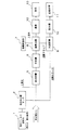
図1は、本発明の一実施態様に係る濾過装置の逆洗方法および装置における逆洗水処理工程のフローを示しており、とくに、発電所における復水フィルタ逆洗水の処理工程の一例を示している。図2は、図1の処理に対応する従来の逆洗水処理工程のフローを示している。
【0015】
図1において、復水フィルタの逆洗用水として、たとえばpH8以上の復水自身が使用され、逆洗後の排水が、復水フィルタ逆洗水1として沈降分離タンクである逆洗水分離タンク2に送られる。一方、図2に示した従来工程では、復水フィルタの逆洗用水として、たとえば純水からなる系統への補給水が使用され、逆洗後の排水が、復水フィルタ逆洗水3として沈降分離タンクである逆洗水分離タンク2に送られるが、このとき、後の沈降分離処理の効率あるいは効果を考慮して、前述したような沈降剤添加工程4が設けられている。
【0016】
逆洗水分離タンク2からの上澄水は、たとえば他系統からの排水が加えられた状態で排水貯槽5に送られ、中和槽6を介して、たとえば凝集剤添加工程7を伴う凝集沈殿処理工程8に送られる。一方、逆洗水分離タンク2における沈降スラッジは、汚泥貯槽9に送られ、凝集沈殿処理工程8からの沈降スラッジとともに貯留されて、脱水機10を介して、産業廃棄物処理工程11(産廃処理)に供される。凝集沈殿処理工程8からの上澄水は、たとえば濾過工程12を経た後、放流工程13に送られる。
【0017】
すなわち、図1に示した本発明の一実施態様に係る濾過装置の逆洗方法および装置においては、図2に示した従来の逆洗方法および装置に比べ、復水フィルタ逆洗水を逆洗水分離タンク2に送ってスラッジの沈降分離処理を行うに際し、逆洗用水にpH8以上の水を使用すること(本実施態様では、pH8以上の復水を使用すること)と、沈降剤を添加しないことが、異なっている。
【0018】
このような処理を簡単に実施するためには、たとえば図3に示すような構成を採ることができる。図3に、本発明の一実施態様に係る濾過装置の逆洗方法および装置を実施するための濾過装置周りのライン構成を、図4に、比較のために、従来のライン構成を、それぞれ示す。
【0019】
たとえば濾材としてプリーツフィルタ21を収容した濾過装置22に対し、図3に示す装置においては、通常の濾過処理のための復水入口ライン23から分岐され、濾過装置の二次側へと接続された逆洗水供給ライン24を介して、復水自身が濾過装置の逆洗用水として供給される。一方、図4に示した従来装置においては、純水からなる補給水が逆洗水供給ライン25を介して、濾過装置の逆洗用水として濾過装置の二次側へ供給される。
【0020】
逆洗は、たとえば逆洗用水と逆洗用空気供給ライン26から供給される空気を用いて行われ、逆洗後の排水が逆洗水としてドレンライン27から前述の逆洗水分離タンク2に送られる。28は、通常の濾過処理後の濾過水を次工程に送る濾過水送給ラインを示している。
【0021】
図1、図3に示したような工程および装置により、pH8以上の逆洗用水(復水)を用いて逆洗が行われる。逆洗後の排水が、濾材から除去された酸化鉄等の微細な捕捉物まで含む逆洗水として逆洗水分離タンク2に送られるが、このとき、従来方法におけるような沈降剤は添加されない。逆洗水分離タンク2に貯留された逆洗水は、pH8以上のアルカリ側にあるから、前述したように酸化鉄粒子のゼータ電位がゼロ近くになり、凝集しやすくなって、スラッジの沈降特性が向上され、沈降スラッジが上澄水と効率よく分離されることになる。この高pHによる沈降特性の向上は、以下の実施例によって確かめられた。
【0022】
【実施例】
加圧水型原子力発電所復水を通水し、復水中の主に酸化鉄からなる懸濁物質を捕捉したプリーツフィルタについて、従来のように純水で逆洗した場合と、pH8以上のプラント系統水で逆洗した場合とについて、沈降分離タンクの逆洗上澄水Fe濃度を調査した。加圧水型原子力発電所二次系の復水水質は一般的にpH9.1〜9.8程度であり、本実施例では9.3の復水であった。
【0023】
プリーツフィルタを純水逆洗、系統水逆洗して得られた逆洗水それぞれ500mlを攪拌後メスシリンダーに入れて静置し、上澄水Fe濃度及びpHを一定時間毎に測定した。結果を表1と図5に示す。
【0024】
【表1】
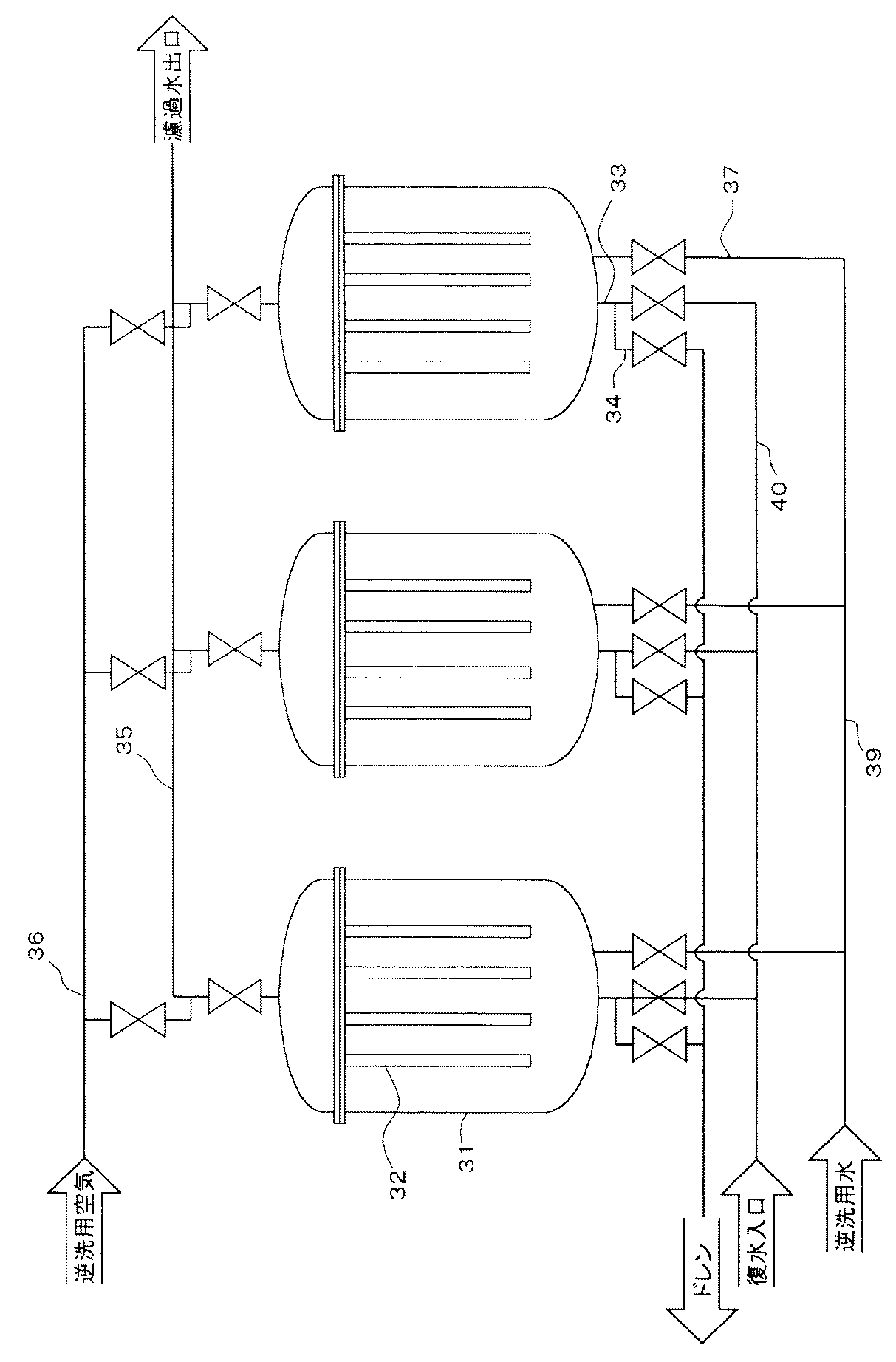
表1、図5から明らかなように、高pHの系統水で逆洗した場合静置後1時間で初期濃度の約1/10、12時間で約1/70までFe濃度が下がったのに対し、純水で逆洗した場合には静置後1時間では初期濃度とほとんど変わらず、12時間でも約1/2程度までしかFe濃度が下がらなかった。この結果から、高pHの系統水で逆洗した場合、明らかに、とくに酸化鉄を主成分とするスラッジの沈降特性向上に効果があることが明らかになった。
【0026】
なお、上記実施例のように、pH8以上の復水等、本発明における逆洗用水としてそのまま使用できる系統水がある場合にはそれを使用すればよいが、このような水がない場合には、周知のpH調整手段を設けてpH8以上の逆洗用水を調製すればよい。
【0027】
また、本発明は、前記図3に示した形態の濾過装置の他にも、図6に示すようなフィルタエレメント吊り下げ型の濾過装置にも適用可能である。図6に示す、本発明の別の実施態様に係る濾過装置の逆洗装置について、図7に示した対応する従来装置と比較しながら説明する。
【0028】
図6、図7に示す濾過装置31においては、フィルタエレメントとしてのプリーツフィルタ32が濾過塔内に吊下された状態で収容されており、装置下部側に復水入口ライン33、ドレンライン34が接続され、上部側に濾過水送給ライン35、逆洗用空気供給ライン36が接続されている。そして、図7に示す従来の逆洗装置では、補給水等を逆洗用水として供給する逆洗水供給母管39からの逆洗水供給ライン37が装置下部側に接続されていたが、図6に示す本発明に係る逆洗装置では、復水母管40からバルブを介し復水分岐ライン41、逆洗水供給母管39を通して、pH8以上のアルカリ側に調整した水を逆洗用水として供給する逆洗水供給ライン38が接続されている。すなわち、図6に示す態様では、pH8以上のアルカリ側に調整した逆洗用水として、復水が用いられている。
【0029】
図6に示した形態において濾過装置31の差圧が上昇し逆洗操作に入る場合、先ず復水入口ライン33についているバルブを閉じ、前段にある復水母管40からの復水の供給を停止し、他の濾過操作を行っている濾過装置の系統から切り離す。その後、逆洗水供給母管39から分岐した逆洗水供給ライン38のバルブを開け、逆洗用水を濾過装置31内に導入する。このとき、復水分岐ライン41のバルブを開け、復水を逆洗用水として導入する。このように、フィルタエレメント吊り下げ型の濾過装置に対しても、本発明は容易に適用することができる。
【0030】
【発明の効果】
以上説明したように、本発明に係る濾過装置の逆洗方法および装置によれば、逆洗用水としてpH8以上のアルカリ側に調整した水を用いることにより、沈降剤を添加することなく、沈降分離タンクにおける特に酸化鉄の沈降特性を向上することができ、上澄水と沈降スラッジを効率よく分離することができ、逆洗水処理のための工程を沈降剤添加なしの簡素なものとすることができるとともに、処理コストを低減することができる。
【図面の簡単な説明】
【図1】本発明の一実施態様に係る濾過装置の逆洗方法および装置における逆洗水処理工程のフロー図である。
【図2】従来の濾過装置の逆洗方法および装置における逆洗水処理工程のフロー図である。
【図3】図1のフローにおける濾過装置周りの配管系統図である。
【図4】図3のフローにおける濾過装置周りの配管系統図である。
【図5】実施例の結果を示す上澄水鉄濃度の遷移特性図である。
【図6】本発明の別の実施態様に係る濾過装置の逆洗方法および装置における濾過装置周りの配管系統図である。
【図7】図6の装置に対応する従来の濾過装置の逆洗方法および装置における濾過装置周りの配管系統図である。
【符号の説明】
1 本発明における復水フィルタ逆洗水
2 逆洗水分離タンク
3 従来の復水フィルタ逆洗水
4 沈降剤添加工程
5 排水貯槽
6 中和槽
7 凝集剤添加工程
8 凝集沈殿処理工程
9 汚泥貯槽
10 脱水機
11 産業廃棄物処理工程
12 濾過工程
13 放流工程
21 プリーツフィルタ
22 濾過装置
23 復水入口ライン
24 本発明における逆洗水供給ライン
25 従来の逆洗水供給ライン
26 逆洗用空気供給ライン
27 ドレンライン
28 濾過水送給ライン
31 濾過装置
32 プリーツフィルタ
33 復水入口ライン
34 ドレンライン
35 濾過水送給ライン
36 逆洗用空気供給ライン
37 従来の逆洗水供給ライン
38 本発明における逆洗水供給ライン
39 逆洗水供給母管
40 復水母管
41 復水分岐ライン[0001]
BACKGROUND OF THE INVENTION
The present invention relates to a backwashing method and apparatus for a filtration device, and more particularly to a method and device suitable for backwashing a filtration device used for condensate treatment in a power plant such as a pressurized water nuclear power plant or a thermal power plant.
[0002]
[Prior art]
In a power plant such as a pressurized water nuclear power plant or a thermal power plant, for example, as one of the methods for treating water, a suspended substance mainly composed of iron oxide in the treated water is filtered, separated and concentrated by a filtration device. ing. When the filtration operation is continued, the trapped amount of suspended substances on the surface of the filter medium increases, and the differential pressure of the filtration device increases. The differential pressure of the filtration device is the sum of the initial differential pressure in a clean state of the filter medium and the differential pressure generated by suspended substances accumulated on the outer surface of the filter medium. When the differential pressure of the filter increases, it is usually backwashed with pure water and air to discharge suspended substances trapped on the surface of the filter medium, return the filter medium to a clean state, and recover the differential pressure of the filter apparatus. I try to let them.
[0003]
As a simple method for treating backwash water discharged during the differential pressure recovery operation, there is a solid-liquid separation that is allowed to stand in a sedimentation separation tank. In this case, the suspended matter in the backwash water settles and can be separated into the suspended matter and the supernatant liquid, the volume of backwash water can be reduced, and the settled sludge is dehydrated and treated as industrial waste. Can be processed.
[0004]
[Problems to be solved by the invention]
However, when fine suspended substances and particles are contained in the backwash water to be treated, they are difficult to settle in the sedimentation separation tank, so that the solid-liquid separation performance is lowered. In particular, the use of a high-performance pleated filter has been studied in recent years, but as a feature of the pleated filter, extremely fine particles that are difficult to settle are captured by the filter with high accuracy. Therefore, since the suspended substance in the backwash water also becomes very fine particles, the sedimentation property of the suspended substance is poor in the sedimentation separation tank, and there is a problem that sufficient solid-liquid separation cannot be easily performed. If the solid-liquid separation performance deteriorates, the dewatering treatment of the settled sludge and the treatment of the supernatant water will be costly and time consuming.
[0005]
Further, in order to prevent or reduce such problems, it is necessary to add a sedimentation agent (precipitation promoter) to the sedimentation separation tank or the path through which the backwash water is introduced. As the precipitating agent, inorganic salts such as Na 2 CO 3 and Na 2 SO 4 , polymer flocculants, PAC (polyaluminum chloride), sulfuric acid bands, FeCl 3 and other inorganic flocculants are usually used. However, when such a precipitating agent is added, the process for that will be needed and processing cost will increase.
[0006]
Therefore, the object of the present invention is to pay attention to the problems in the backwashing water treatment of the filtration device for performing the backwashing with pure water and air as described above, and in particular, without adding a settling agent, the efficiency of iron oxide is improved. It is an object of the present invention to provide a backwashing method and apparatus for a filtration device that can be well separated, simplify the process for backwashing water treatment, and reduce the cost.
[0007]
[Means for Solving the Problems]
In order to solve the above-mentioned problem, the backwashing method for a filtration device according to the present invention is used as a backwashing water for a filtration device for performing backwashing with pure water and air, on the alkali side having a pH of 8 or more instead of pure water. It consists of a method characterized by using adjusted water.
[0008]
Moreover, the backwashing device of the filtration device according to the present invention uses water adjusted to the alkali side having a pH of 8 or more instead of pure water as backwashing water for the filtration device for backwashing with pure water and air. Consists of features.
[0009]
Examples of the filter medium include a hollow fiber membrane filter, a ceramic filter, a carbon filter, an electromagnetic filter, and a pleat filter. The backwashing method and apparatus for a filtration apparatus according to the present invention are particularly effective when a pleat filter is used. Is. The pleated filter is a filter material that has been processed into a pleated shape and has an increased surface area for filtration. As described above, the pleated filter has the feature that it can capture fine particles that are difficult to settle with high accuracy. Suspended substances in the washing water also become very fine particles, and the sedimentation property of the suspended substances in the sedimentation tank is poor and sufficient solid-liquid separation cannot be easily performed. Fine suspended solids, particularly iron oxide, can be settled and separated satisfactorily.
[0010]
In such a method and apparatus, the filtration apparatus is provided with a line for introducing the backwash water adjusted to the alkali side into the filtration apparatus (for example, a line for introducing it into the secondary side of the filtration apparatus) and vice versa. It is preferable that washing water can be easily introduced into the filtration device.
[0011]
Further, the backwashing method and apparatus for the filtration device according to the present invention is particularly effective for backwashing the filtration device provided in the power plant, and the system water of the power plant, for example, condensate is used as the backwash water. Can be used. In the power plant, in particular, a backwash type filtration device intended to remove iron oxide is used. For example, in the case of a pressurized water nuclear power plant, a secondary condensate filter is an object of the present invention and will be applied in the future. It is also considered possible to apply to a filter provided in a high-temperature heater drain system or a water supply system. For thermal power plants, condensate filters, boiler blow water recovery water filters, and the like are subject to application of the present invention. Furthermore, the condensate filter, the equipment drain filter, etc. can be applied to the boiling water nuclear power plant.
[0012]
In the present invention, the water adjusted to the alkali side having a pH of 8 or higher, which is used as the backwash water for the filtration device, can be prepared with a special pH adjusting means to prepare the backwash water in the target pH range. However, particularly in pressurized water nuclear power plants and thermal power plants, system water, particularly condensate, has an alkaline pH, and can be used as it is as backwash water. The pH of the condensate of pressurized water nuclear power plants in Japan is normally operated in the range of about 9.1 to 9.8, and the pH of condensate of thermal power plants is usually about 8.5 to 9.5. It is operated in the range of. The pH of the backwash water in the present invention is 8 or more, and may be operated in the range of 8 to 10, for example. Preferably, the pH is in the range of 8.5 to 9.9, more preferably in the range of 8.9 to 9.9. Therefore, it is possible to use the system water in the pressurized water nuclear power plant and the thermal power plant as described above without further pH adjustment. However, in a boiling water nuclear power plant, since condensate is normally neutral, it is necessary to provide a pH adjusting means so as to be within the pH range defined in the present invention.
[0013]
In such a backwashing method and apparatus for a filtering device according to the present invention, backwashing water having a pH of 8 or more, for example, system water having a pH of 8 or more, is not used as the backwashing water for the filtering device. By using this, the pH in the backwash water can be raised, and the sedimentation property in the sedimentation tank that performs the backwash water treatment, particularly the sedimentation property of fine iron oxide can be improved. This improvement in iron oxide sedimentation is considered to be achieved for the following reasons. That is, in general, iron oxide has a slight difference depending on the chemical form, but the zeta potential representing the charged state of the particles is close to zero at pH around 8-9. The zeta potential is used as an index of the dispersion stability of dispersed particles. When the absolute value of the zeta potential increases, the repulsive force between the particles increases and the stability of the particles increases. Conversely, when the zeta potential is close to zero, the particles tend to aggregate. Therefore, by using water having a pH of 8 or more, particularly water having a pH of about 8 to 10 as the backwash water, the zeta potential can be made close to zero and the sedimentation property of the microsuspended substance in the backwash water can be improved. In addition, without adding a settling agent, it is possible to efficiently separate into a sedimentation sludge having a sufficiently high concentration and a supernatant water having a sufficiently low concentration in a sedimentation separation tank. As a result, it is possible to facilitate backwash water treatment and reduce treatment costs.
[0014]
DETAILED DESCRIPTION OF THE INVENTION
Hereinafter, preferred embodiments of the present invention will be described with reference to the drawings.
FIG. 1 shows a flow of a backwashing water treatment process in a backwashing method and apparatus for a filtration device according to an embodiment of the present invention, and in particular, an example of a treatment process of condensate filter backwashing water in a power plant. Show. FIG. 2 shows a flow of a conventional backwash water treatment process corresponding to the treatment of FIG.
[0015]
In FIG. 1, for example, condensate having a pH of 8 or higher is used as backwash water for the condensate filter, and the drained water after backwashing is a backwash
[0016]
The supernatant water from the backwash
[0017]
That is, in the backwashing method and apparatus of the filtration apparatus according to one embodiment of the present invention shown in FIG. 1, the backwashing water of the condensate filter is backwashed as compared with the conventional backwashing method and apparatus shown in FIG. When the sludge is sent to the
[0018]
In order to easily carry out such processing, for example, a configuration as shown in FIG. 3 can be adopted. FIG. 3 shows a line configuration around the filtration device for carrying out the backwashing method and apparatus of the filtration device according to one embodiment of the present invention, and FIG. 4 shows a conventional line configuration for comparison. .
[0019]
For example, in the device shown in FIG. 3, the
[0020]
The backwashing is performed using, for example, backwashing water and air supplied from the backwashing
[0021]
Backwashing is performed using backwashing water (condensate) having a pH of 8 or higher by the processes and apparatuses shown in FIGS. The drained water after backwashing is sent to the backwashing
[0022]
【Example】
For pleated filters that pass through the condensate of a pressurized water nuclear power plant and capture suspended substances mainly composed of iron oxide in the condensate, when the water is backwashed with pure water as in the past, plant system water with a pH of 8 or higher The backwash supernatant water Fe concentration in the sedimentation separation tank was investigated for the case of backwashing with the above. The condensate quality of the secondary system of the pressurized water nuclear power plant is generally about pH 9.1 to 9.8, and in this example, it was 9.3 condensate.
[0023]
500 ml each of backwashing water obtained by backwashing the pleated filter with pure water and system water was stirred and placed in a measuring cylinder and allowed to stand, and the Fe concentration and pH of the supernatant water were measured at regular intervals. The results are shown in Table 1 and FIG.
[0024]
[Table 1]
As is clear from Table 1 and FIG. 5, the Fe concentration decreased to about 1/10 of the initial concentration in 1 hour after standing and about 1/70 in 12 hours when backwashed with high pH system water. On the other hand, when backwashed with pure water, the concentration was almost the same as the initial concentration in 1 hour after standing, and the Fe concentration decreased only to about ½ even in 12 hours. From this result, it was clarified that, when backwashing with high pH system water, it is effective in improving the sedimentation characteristics of sludge mainly composed of iron oxide.
[0026]
In addition, when there is system water that can be used as it is as backwash water in the present invention, such as condensate having a pH of 8 or more, as in the above embodiment, it may be used. A well-known pH adjusting means may be provided to prepare water for backwashing having a pH of 8 or higher.
[0027]
Further, the present invention can be applied to a filter element hanging type filter device as shown in FIG. 6 in addition to the filter device shown in FIG. A backwashing device for a filtration device according to another embodiment of the present invention shown in FIG. 6 will be described in comparison with the corresponding conventional device shown in FIG.
[0028]
In the
[0029]
In the embodiment shown in FIG. 6, when the differential pressure of the
[0030]
【The invention's effect】
As described above, according to the backwashing method and apparatus of the filtration device according to the present invention, by using water adjusted to the alkali side having a pH of 8 or more as backwashing water, sedimentation separation is performed without adding a precipitating agent. In particular, the sedimentation characteristics of iron oxide in the tank can be improved, the supernatant water and the sedimented sludge can be separated efficiently, and the process for backwash water treatment can be simplified without the addition of a sedimentation agent. In addition, the processing cost can be reduced.
[Brief description of the drawings]
FIG. 1 is a flowchart of a backwashing water treatment process in a backwashing method and apparatus for a filtration device according to an embodiment of the present invention.
FIG. 2 is a flow diagram of a backwashing water treatment process in a conventional backwashing method and device for a filtration device.
FIG. 3 is a piping system diagram around a filtration device in the flow of FIG. 1;
4 is a piping system diagram around a filtration device in the flow of FIG. 3;
FIG. 5 is a transition characteristic diagram of supernatant water iron concentration showing the results of Examples.
FIG. 6 is a piping system diagram around the filtration device in the backwashing method and device of the filtration device according to another embodiment of the present invention.
7 is a piping system diagram around the filtration device in the conventional backwashing method and device of the filtration device corresponding to the device of FIG. 6;
[Explanation of symbols]
DESCRIPTION OF SYMBOLS 1 Condensate
Claims (10)
Priority Applications (1)
| Application Number | Priority Date | Filing Date | Title |
|---|---|---|---|
| JP2001391626A JP3852829B2 (en) | 2001-12-25 | 2001-12-25 | Filtration device backwash method and apparatus |
Applications Claiming Priority (1)
| Application Number | Priority Date | Filing Date | Title |
|---|---|---|---|
| JP2001391626A JP3852829B2 (en) | 2001-12-25 | 2001-12-25 | Filtration device backwash method and apparatus |
Publications (2)
| Publication Number | Publication Date |
|---|---|
| JP2003190717A JP2003190717A (en) | 2003-07-08 |
| JP3852829B2 true JP3852829B2 (en) | 2006-12-06 |
Family
ID=27599161
Family Applications (1)
| Application Number | Title | Priority Date | Filing Date |
|---|---|---|---|
| JP2001391626A Expired - Fee Related JP3852829B2 (en) | 2001-12-25 | 2001-12-25 | Filtration device backwash method and apparatus |
Country Status (1)
| Country | Link |
|---|---|
| JP (1) | JP3852829B2 (en) |
-
2001
- 2001-12-25 JP JP2001391626A patent/JP3852829B2/en not_active Expired - Fee Related
Also Published As
| Publication number | Publication date |
|---|---|
| JP2003190717A (en) | 2003-07-08 |
Similar Documents
| Publication | Publication Date | Title |
|---|---|---|
| CN100450592C (en) | Metal smelting factory sewage reclaiming method based on membrane filtering technique | |
| JP2944939B2 (en) | Desulfurization wastewater treatment method and apparatus | |
| JP3945541B2 (en) | Physicochemical treatment method of runoff water for consumption, especially surface water | |
| CN209210544U (en) | High ammonia nitrogen, high-sulfur compound garbage percolation liquid treating system | |
| EP0087268B1 (en) | Process for treating sludge | |
| CN102656122B (en) | Enhanced high water recovery membrane process | |
| JP2772612B2 (en) | Water filtration method containing dissolved manganese using permeable membrane | |
| JP2911327B2 (en) | Method and apparatus for treating water containing turbid components | |
| JP2005118608A (en) | Water treatment method | |
| JP3852829B2 (en) | Filtration device backwash method and apparatus | |
| WO2019150604A1 (en) | Method and apparatus for treating coal wastewater | |
| JP2009183901A (en) | Membrane filtration concentration method of coagulation treated water and coagulated waste muddy water | |
| KR101726482B1 (en) | Pressurized membrane filtration system with submerged membrane filtration process and water treatment method using the same | |
| JP2007098270A (en) | Method and apparatus for producing pure water | |
| JP3262015B2 (en) | Water treatment method | |
| JP4401251B2 (en) | General waste incineration wastewater treatment method | |
| JP3185398B2 (en) | Water purification equipment | |
| JP7441108B2 (en) | Water treatment method and water treatment equipment | |
| JP2008279339A (en) | Solid/liquid separation apparatus | |
| CN105084596A (en) | Circular comprehensive rainwater treatment device and method | |
| JP4033671B2 (en) | Coal storage muddy water purification device and coal muddy muddy water purification method | |
| JP2005193125A (en) | Waste sludge treatment method of water purification plant | |
| JP2004074146A (en) | Method and equipment for treating impurity-containing liquid | |
| JP2001321795A (en) | Liquid cleaning apparatus | |
| JP3667154B2 (en) | Biological contact filtration method and apparatus |
Legal Events
| Date | Code | Title | Description |
|---|---|---|---|
| A621 | Written request for application examination |
Free format text: JAPANESE INTERMEDIATE CODE: A621 Effective date: 20040709 |
|
| A977 | Report on retrieval |
Free format text: JAPANESE INTERMEDIATE CODE: A971007 Effective date: 20060118 |
|
| A131 | Notification of reasons for refusal |
Free format text: JAPANESE INTERMEDIATE CODE: A131 Effective date: 20060120 |
|
| A521 | Request for written amendment filed |
Free format text: JAPANESE INTERMEDIATE CODE: A523 Effective date: 20060322 |
|
| A131 | Notification of reasons for refusal |
Free format text: JAPANESE INTERMEDIATE CODE: A131 Effective date: 20060414 |
|
| A521 | Request for written amendment filed |
Free format text: JAPANESE INTERMEDIATE CODE: A523 Effective date: 20060428 |
|
| TRDD | Decision of grant or rejection written | ||
| A01 | Written decision to grant a patent or to grant a registration (utility model) |
Free format text: JAPANESE INTERMEDIATE CODE: A01 Effective date: 20060901 |
|
| A61 | First payment of annual fees (during grant procedure) |
Free format text: JAPANESE INTERMEDIATE CODE: A61 Effective date: 20060901 |
|
| R150 | Certificate of patent or registration of utility model |
Ref document number: 3852829 Country of ref document: JP Free format text: JAPANESE INTERMEDIATE CODE: R150 Free format text: JAPANESE INTERMEDIATE CODE: R150 |
|
| FPAY | Renewal fee payment (event date is renewal date of database) |
Free format text: PAYMENT UNTIL: 20090915 Year of fee payment: 3 |
|
| FPAY | Renewal fee payment (event date is renewal date of database) |
Free format text: PAYMENT UNTIL: 20100915 Year of fee payment: 4 |
|
| R250 | Receipt of annual fees |
Free format text: JAPANESE INTERMEDIATE CODE: R250 |
|
| FPAY | Renewal fee payment (event date is renewal date of database) |
Free format text: PAYMENT UNTIL: 20110915 Year of fee payment: 5 |
|
| R250 | Receipt of annual fees |
Free format text: JAPANESE INTERMEDIATE CODE: R250 |
|
| FPAY | Renewal fee payment (event date is renewal date of database) |
Free format text: PAYMENT UNTIL: 20120915 Year of fee payment: 6 |
|
| R250 | Receipt of annual fees |
Free format text: JAPANESE INTERMEDIATE CODE: R250 |
|
| FPAY | Renewal fee payment (event date is renewal date of database) |
Free format text: PAYMENT UNTIL: 20130915 Year of fee payment: 7 |
|
| R250 | Receipt of annual fees |
Free format text: JAPANESE INTERMEDIATE CODE: R250 |
|
| R250 | Receipt of annual fees |
Free format text: JAPANESE INTERMEDIATE CODE: R250 |
|
| R250 | Receipt of annual fees |
Free format text: JAPANESE INTERMEDIATE CODE: R250 |
|
| R250 | Receipt of annual fees |
Free format text: JAPANESE INTERMEDIATE CODE: R250 |
|
| R250 | Receipt of annual fees |
Free format text: JAPANESE INTERMEDIATE CODE: R250 |
|
| R250 | Receipt of annual fees |
Free format text: JAPANESE INTERMEDIATE CODE: R250 |
|
| R250 | Receipt of annual fees |
Free format text: JAPANESE INTERMEDIATE CODE: R250 |
|
| R250 | Receipt of annual fees |
Free format text: JAPANESE INTERMEDIATE CODE: R250 |
|
| R250 | Receipt of annual fees |
Free format text: JAPANESE INTERMEDIATE CODE: R250 |
|
| LAPS | Cancellation because of no payment of annual fees |