JP3852017B2 - Firewall device - Google Patents
Firewall device Download PDFInfo
- Publication number
- JP3852017B2 JP3852017B2 JP2005504855A JP2005504855A JP3852017B2 JP 3852017 B2 JP3852017 B2 JP 3852017B2 JP 2005504855 A JP2005504855 A JP 2005504855A JP 2005504855 A JP2005504855 A JP 2005504855A JP 3852017 B2 JP3852017 B2 JP 3852017B2
- Authority
- JP
- Japan
- Prior art keywords
- user
- filtering
- firewall
- user terminal
- individual
- Prior art date
- Legal status (The legal status is an assumption and is not a legal conclusion. Google has not performed a legal analysis and makes no representation as to the accuracy of the status listed.)
- Expired - Fee Related
Links
Images


Classifications
-
- H—ELECTRICITY
- H04—ELECTRIC COMMUNICATION TECHNIQUE
- H04L—TRANSMISSION OF DIGITAL INFORMATION, e.g. TELEGRAPHIC COMMUNICATION
- H04L63/00—Network architectures or network communication protocols for network security
- H04L63/02—Network architectures or network communication protocols for network security for separating internal from external traffic, e.g. firewalls
- H04L63/0227—Filtering policies
-
- H—ELECTRICITY
- H04—ELECTRIC COMMUNICATION TECHNIQUE
- H04L—TRANSMISSION OF DIGITAL INFORMATION, e.g. TELEGRAPHIC COMMUNICATION
- H04L63/00—Network architectures or network communication protocols for network security
- H04L63/08—Network architectures or network communication protocols for network security for authentication of entities
-
- H—ELECTRICITY
- H04—ELECTRIC COMMUNICATION TECHNIQUE
- H04L—TRANSMISSION OF DIGITAL INFORMATION, e.g. TELEGRAPHIC COMMUNICATION
- H04L63/00—Network architectures or network communication protocols for network security
- H04L63/14—Network architectures or network communication protocols for network security for detecting or protecting against malicious traffic
- H04L63/1441—Countermeasures against malicious traffic
- H04L63/1466—Active attacks involving interception, injection, modification, spoofing of data unit addresses, e.g. hijacking, packet injection or TCP sequence number attacks
Description
この発明は、インターネットなどの外部ネットワークに接続するユーザを保護するためのファイアウォール装置に関する。 The present invention relates to a firewall device for protecting users connected to an external network such as the Internet.
自己の端末、または、自己のネットワークのセキュリティを高める手段の1つとして、ファイアウォール(FWとも称する)がある。 There is a firewall (also referred to as FW) as one of means for enhancing the security of the own terminal or the own network.
ファイアウォールは、セキュリティを高めたい自己の端末または自己のネットワークと外部ネットワークとの間に配置され、予め決められたセキュリティポリシに従い、外部ネットワークから自己の端末またはネットワークに向かうパケット、または、自己の端末またはネットワークから外部ネットワークヘ向かうパケットに対して、通過が可能かどうかを判断し、可能な場合は、当該パケットを通過させ、可能でない場合は、当該パケットを破棄するフィルタリング処理を実施する。 The firewall is arranged between the own terminal or the own network that wants to increase security, and the own network and the external network, and in accordance with a predetermined security policy, the packet from the external network to the own terminal or the network, or the own terminal or It is determined whether or not the packet going from the network to the external network can be passed. If it is possible, the packet is allowed to pass. If not, filtering processing for discarding the packet is performed.
セキュリティポリシは、アドレス、プロトコル種別、ポート番号、方向、通過の可否、または他の条件を結びつけ、1つのルールとし、当該ルールを複数まとめたものである。 The security policy combines an address, a protocol type, a port number, a direction, passability, or other conditions as one rule, and a plurality of such rules are collected.
また、ファイアウォールは設置場所により、3つに区分することができる。 The firewall can be divided into three types according to the installation location.
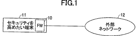
1つは、図1に示すように、ファイアウォール10を自己の端末内部に保持するもの(以下、端末ベースファイアウォールと称する)で、自己の端末11を外部ネットワーク(例えば、インターネット)12から守るために利用されている。
One is to hold a
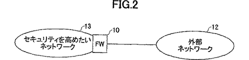
もう1つは、図2に示すように、ファイアウォール10を自己のネットワーク13のエッジに設置され、外部ネットワーク12に接続するもの(以下、CPEベースファイアウォールと称する)で、自己のネットワーク13を外部ネットワーク12から守るために利用される。
As shown in FIG. 2, the
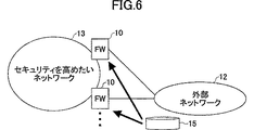
もう1つは、図3に示すように、ファイアウォール10が、独立のポリシで運用されるセキュリティを高めたいネットワーク13または端末11を複数収容し、外部ネットワーク12に接続する位置に設置されるもの(以下、NWベースファイアウォールと称する)で、個々のネットワーク13または端末11を外部ネットワーク12から守るために利用される。
As shown in FIG. 3, the
常時接続ユーザが増加するとともに、セキュリティの必要性が高まる中、セキュリティ知識が不十分なユーザに対し、低コストでスキル不足を解消するセキュリティサービスを提供することが求められているという観点からは、上記のファイアウォールのうち、ネットワーク側にファイアウォールを配備するNWベースファイアウォールが有効である。 As the number of constantly connected users increases and the need for security increases, it is required to provide security services that solve the lack of skills at low cost for users with insufficient security knowledge. Of the above firewalls, an NW-based firewall that deploys a firewall on the network side is effective.
すなわち、NWベースファイアウォールにより、収容ユーザの集約による経済化と、アウトソーシングによるユーザ稼動の軽減が期待される。ただし、セキュリティポリシをユーザ毎に提供する必要もあり、本方法によるファイアウォールでは、1台の物理的なファイアウォールにユーザ毎の仮想ファイアウォールを構築するアーキテクチャが求められる。 In other words, the NW-based firewall is expected to be economical by consolidating accommodated users and reduce user operations by outsourcing. However, it is necessary to provide a security policy for each user, and the firewall according to this method requires an architecture for constructing a virtual firewall for each user on one physical firewall.
従来技術の仮想ファイアウォールの構築法を図4に示す。従来技術によるユーザの端末あるいはサーバ、またはユーザのネットワークと仮想ファイアウォールとの割り当ては、固定的なユーザIDと仮想ファイアウォールIDとを対応させることにより実現する。 FIG. 4 shows a conventional method for constructing a virtual firewall. Allocation between a user terminal or server or a user network and a virtual firewall according to the prior art is realized by associating a fixed user ID with a virtual firewall ID.
ここで固定的なユーザIDとは、ユーザの端末やサーバが属するネットワークのVLAN−IDやユーザの端末やサーバのIPアドレスである。図4では、ユーザ#aのサーバ211のIPアドレス[a.a.a.a]、ユーザ♯bのサーバ212のIPアドレス[b.b.b.b]を、それぞれ固定的なユーザIDとして、また、これらをそれぞれ仮想ファイアウォールID202および203と対応づけ、振分け管理テーブル201に事前に登録される。
Here, the fixed user ID is the VLAN-ID of the network to which the user terminal or server belongs, or the IP address of the user terminal or server. In FIG. 4, the IP address [a. a. a. a], the IP address of
そして例えば、サーバ211とユーザ#aの接続相手端末213との間の通信において、サーバ211から送信されるパケット221に対し、その送信元IPアドレス[a.a.a.a]を検索キーとして振分け管理テーブル201を参照し、該送信元IPアドレス[a.a.a.a]と対応付けられている仮想ファイアウォールID202を検索し、該パケット221を仮想ファイアウォール202に振り分ける。また、接続相手端末213から送信されるパケット222に対し、その宛先IPアドレスb.b.b.bを検索キーとして振分け管理テーブル201を参照し、該宛先IPアドレスb.b.b.bと対応付けられている仮想ファイアウォールID203を検索し、該パケット222を仮想ファイアウォール203に振り分ける。
For example, in the communication between the
仮想ファイアウォール202、203には、それぞれユーザ#a、ユーザ#bが定めるセキュリティポリシに従うフィルタリングルールが記載されており、このルールに従い、パケット221および222は通過あるいは廃棄処理される。これによって不正アクセス者からのサーバ211に対する攻撃パケットをフィルタリングすることができる。
The
この従来技術は、主にデータセンタ等を適用先としており、そこでは固定的なユーザIDを用いているため、ユーザIDを振分け管理テーブル201に事前に登録することが可能である。 This prior art mainly applies to a data center or the like, and uses a fixed user ID therein, so that the user ID can be registered in the distribution management table 201 in advance.
なお、上記の従来技術に関連する先行技術文献として、「データセンタにおけるセキュアなコンテンツ・フィルタリング方式の検討」(電子情報通信学会ソサイエティ大会(2002)B-6-38 2002.8.20発行)がある。 As a prior art document related to the above prior art, there is “Study of secure content filtering method in data center” (published by Society of Electronics, Information and Communication Engineers Society (2002) B-6-38 2002.8.20).
また、ユーザ毎のセキュリティ通信を設定するもう1つの従来技術として、「セキュリティ通信方法、通信システム及びその装置」(特開2001−298449号公報)がある。しかし本従来技術は、主にIPSec通信を想定しており、そこで定義されるユーザ毎のセキュリティ通信とは、通信に用いる認証アルゴリズムや暗号化アルゴリズムの強度を、ユーザの要求に応じ決定するというものにすぎず、不正アクセスからの攻撃パケットをフィルタリングする機能とは異なる。 As another conventional technique for setting security communication for each user, there is a “security communication method, communication system and apparatus” (Japanese Patent Laid-Open No. 2001-298449). However, this conventional technique mainly assumes IPSec communication, and security communication for each user defined therein determines the strength of an authentication algorithm or encryption algorithm used for communication according to a user's request. However, it is different from the function of filtering attack packets from unauthorized access.
ユーザが利用する常時接続サービスにおいては、ユーザID(ユーザIPアドレス)はユーザ端末とネットワークとの接続が確立されるときに初めて付与される。具体的には、PPP(Point to Point Protocol)セッションの確立時に初めて付与される。また、ユーザIPアドレスは一般に可変である。 In a constant connection service used by a user, a user ID (user IP address) is given for the first time when a connection between a user terminal and a network is established. Specifically, it is given for the first time when a PPP (Point to Point Protocol) session is established. The user IP address is generally variable.
従って、上記の従来技術における仮想ファイアウォールを常時接続サービスに適用しようとしても、振分け管理テーブルにユーザIPアドレスを事前登録することができないので、従来技術における仮想ファイアウォールを常時接続サービスに適用することは困難である。 Therefore, even if the above-described conventional virtual firewall is applied to the always-on service, it is difficult to apply the conventional virtual firewall to the always-on service because the user IP address cannot be pre-registered in the distribution management table. It is.
また、常時接続サービスの場合、データセンタ等への適用の場合と比較し、収容ユーザ数が断然に多いことから、NWベースのファイアウォール装置に多重に収容するユーザ数を増大させることが求められている。 In the case of always-on services, the number of accommodated users is far greater than when applied to data centers and the like, and there is a need to increase the number of users accommodated in an NW-based firewall device. Yes.
さて、ファイアウォールの配置場所という観点とは別に、ファイアウォールをセキュリティポリシの保持方法の観点から分類すると以下の2つに分類することができる。 Apart from the viewpoint of the location of the firewall, if the firewall is classified from the viewpoint of the security policy holding method, it can be classified into the following two.
1つは、セキュリティポリシをファイアウォール内部に保持するものであり、通常のファイアウォールはこの方法が用いられている。 One is to hold the security policy inside the firewall, and this method is used for a normal firewall.
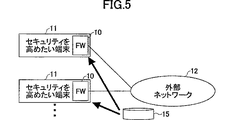
もう1つは、図5、図6、図7に示すように、セキュリティポリシ15をファイアウォール10の外部に保持し、複数のファイアウォール10に、このセキュリティポリシを配布するものである。
The other is to hold a
先に示したどの種類のファイアウォール(端末ベースファイアウォール、CPEベースファイアウォール、あるいは、NWベースファイアウォール)も、その多くはセキュリティポリシをファイアウォール内部に保持するものである。 Any of the types of firewalls described above (terminal-based firewall, CPE-based firewall, or NW-based firewall) often hold security policies within the firewall.
しかし、セキュリティポリシを分配する方法を用いるファイアウォールに関しても、特表2002−544607号公報により、端末ベースファイアウォールへの適用が示されており、また、文献(「Distributed FirewalIs」(Nov.1999, Special lssue on Security, ISSN l044-63971))により、CPEべースファイアウォールへの適用が示されている。 However, regarding a firewall using a method for distributing a security policy, application to a terminal-based firewall is shown in Japanese Patent Publication No. 2002-544607, and the literature (“Distributed FirewalIs” (Nov. 1999, Special lssue on Security, ISSN 1044-63971)) shows application to CPE-based firewalls.
また、NWベースファイアウォールにおいても、収容するネットワークまたは端末が静的に接続される場合は、CPEベースファイアウォールと同様に考えられる。 In the NW-based firewall, when a network or a terminal to be accommodated is statically connected, it can be considered in the same manner as the CPE-based firewall.
しかし、NWベースファイアウォールで、収容するネットワークまたは端末が動的に接続、切断を行い、または、収容されるNWベースファイアウォールを変更する場合においては、ファイアウォール内部にセキュリティポリシを保持する方法は、ネットワークまたは端末の接続、切断に関係無く、ファイアウォールが収容する可能性のあるネットワークまたは端末に関するセキュリティポリシを全て保持しなければならないため有用でない。 However, when the network or terminal to be accommodated dynamically connects or disconnects with the NW-based firewall, or when the accommodated NW-based firewall is changed, the method of maintaining the security policy inside the firewall is the network or Regardless of the connection or disconnection of the terminal, it is not useful because all security policies related to the network or terminal that can be accommodated by the firewall must be maintained.
よって、このような環境では、ネットワークまたは端末の接続、あるいは切断に合わせ、保持するセキュリティポリシ容量を最適に保つ手段を有するNWベースファイアウォール装置が必要になる。 Therefore, in such an environment, an NW-based firewall device having means for keeping the security policy capacity to be held optimally in accordance with connection or disconnection of a network or a terminal is required.
また、NWベースファイアウォールには、複数のネットワークまたは端末が接続されるため、前記のネットワークまたは端末の接続に合わせてセキュリティポリシをロードする手段を有するNWベースファイアウォールでは、多量のセキュリティポリシをロードする場合があり、この場合、NWベースファイアウォールのCPUは、ロード用の処理が大きくなり、フィルタリングおよび転送用の処理ができず、フィルタリングおよび転送性能に影響を及ぼす。 In addition, since a plurality of networks or terminals are connected to the NW base firewall, a large amount of security policies are loaded in the NW base firewall having means for loading a security policy in accordance with the connection of the network or terminal. In this case, the CPU of the NW-based firewall has a large load process, cannot perform the filtering and forwarding process, and affects the filtering and forwarding performance.
また、セキュリティポリシを配布する装置においても、配布量が装置性能を超えた場合、セキュリティポリシを配布できなくなる。 Even in a device that distributes a security policy, if the distribution amount exceeds the device performance, the security policy cannot be distributed.
さらに、セキュリティポリシの配布に用いられている回線においても、配布量が回線容量を超えた場合、セキュリティポリシの廃棄または遅延が生じることになる。 Further, even in a line used for security policy distribution, if the distribution amount exceeds the line capacity, the security policy is discarded or delayed.
従って、配布するセキュリティポリシ量を抑える手段を有するNWベースファイアウォール装置が必要になる。
本発明の第1の目的は、事前にユーザIDと仮想ファイアウォールIDとの対応付けができない通信形態に対してもサービス提供可能なファイアウォール装置を提供することである。 A first object of the present invention is to provide a firewall apparatus capable of providing a service even for a communication mode in which a user ID and a virtual firewall ID cannot be associated in advance.
また、本発明の第2の目的は、収容するユーザ多重数を増大させることのできるファイアウォール装置を提供することである。 A second object of the present invention is to provide a firewall device that can increase the number of multiplexed users.
更に、本発明の第3の目的は、収容するネットワークまたは端末の接続または切断に応じて必要なセキュリティポリシを保持または破棄することを可能にし、且つ、ロードするセキュリティポリシ量を軽減することが可能なファイアウォール装置を提供することである。 Furthermore, a third object of the present invention is to enable holding or discarding a necessary security policy according to connection or disconnection of a network or terminal to be accommodated, and to reduce the amount of security policy to be loaded. Providing a secure firewall device.
上記の第1の目的は、複数の仮想ファイアウォールを有し、各仮想ファイアウォールはそれぞれ独立したフィルタリングポリシを有するファイアウォール装置であって、
ユーザ名と仮想ファイアウォールIDを管理する振分け管理テーブルと、
ユーザ端末からのネットワーク接続のための認証情報を受信すると、それに記載されているユーザ名を保持する手段と、
認証情報を認証サーバに通知する手段と、
前記認証サーバから、認証応答を受信すると、その応答に記載されている前記ユーザ端末に付与すべきユーザIDを保持する手段とを備え、
前記ユーザIDを前記ユーザ名と対応付けて前記振分け管理テーブルに登録するファイアウォール装置により達成できる。
The first object is a firewall device having a plurality of virtual firewalls, each virtual firewall having an independent filtering policy,
A distribution management table for managing user names and virtual firewall IDs;
When receiving authentication information for network connection from the user terminal, means for holding the user name described therein,
Means for notifying the authentication server of authentication information;
When receiving an authentication response from the authentication server, a means for holding a user ID to be given to the user terminal described in the response,
This can be achieved by a firewall device that registers the user ID in the distribution management table in association with the user name.
本発明によれば、事前にユーザIDと仮想ファイアウォールIDとの対応付けができない通信形態に対しても、ユーザ端末からのネットワーク接続のための認証情報を利用し、動的にユーザIDと仮想ファイアウォールIDとを対応付けることができる。そして、そのユーザIDのユーザ端末が送信あるいは受信するパケットに対し、そのユーザ端末に対応するセキュリティポリシに従うフィルタリングルールを適用することができる。 According to the present invention, even for a communication mode in which a user ID cannot be associated with a virtual firewall ID in advance, authentication information for network connection from the user terminal is used to dynamically change the user ID and virtual firewall ID. An ID can be associated. And the filtering rule according to the security policy corresponding to the user terminal can be applied to the packet transmitted or received by the user terminal of the user ID.
また、上記の第2の目的は、ユーザ名と、ユーザIDと、フィルタリングIDとを対応付けて管理する振分け管理テーブルと、
前記フィルタリングIDによって特定され、それぞれ独立したフィルタリングポリシを有するフィルタリングテーブルと、
ネットワーク接続開始時に、ユーザ端末から発行される、ユーザ名が記載された認証情報を受信し、当該ユーザ名を保持する手段と、
前記認証情報を認証サーバに通知する手段と、
前記認証サーバから認証応答を受信し、その認証応答に記載されている前記ユーザ端末に付与すべきユーザIDを保持する手段とを備え、
前記ユーザIDを前記ユーザ名と対応付けて前記振分け管理テーブルに登録するファイアウォール装置によって達成できる。
In addition, the second purpose described above is a distribution management table that manages user names, user IDs, and filtering IDs in association with each other,
A filtering table identified by the filtering ID and having an independent filtering policy;
Means for receiving authentication information in which a user name is issued issued from a user terminal at the start of network connection and holding the user name;
Means for notifying the authentication server of the authentication information;
Means for receiving an authentication response from the authentication server and holding a user ID to be given to the user terminal described in the authentication response;
This can be achieved by a firewall device that registers the user ID in the distribution management table in association with the user name.
本発明によれば、フィルタリングIDを導入し、ユーザ毎のフィルタリングポリシをフィルタリングIDによって識別するので、例えば、各仮想ファイアウォールに複数の独立したフィルタリングポリシを管理することができ、ユーザ多重数を向上させることができる。 According to the present invention, the filtering ID is introduced and the filtering policy for each user is identified by the filtering ID. For example, a plurality of independent filtering policies can be managed in each virtual firewall, and the number of multiplexed users is improved. be able to.
また、ユーザ毎のパケットの検索範囲は、付与されたフィルタリングIDの値と一致するテーブルのみを検索対象とするため、検索処理時間が不必要に長くなるのを抑制することができる。 In addition, since the search range of the packet for each user is only a table that matches the value of the assigned filtering ID, the search processing time can be prevented from becoming unnecessarily long.
また、本願発明では、前述のフィルタリングIDを、さらに個別フィルタリングIDと共通フィルタリングIDに2分化し、各ユーザ個別のフィルタリングポリシは個別フィルタリングテーブルに記載し、複数のユーザにて共通化することが可能なフィルタリングポリシは共通フィルタリングテーブルに記載することもできる。 In the present invention, the above-mentioned filtering ID can be further divided into an individual filtering ID and a common filtering ID, and each user's individual filtering policy can be described in an individual filtering table and shared by a plurality of users. These filtering policies can be described in the common filtering table.
これにより、例えば、10ユーザが2つの同じフィルタリングルールを利用している場合、従来技術を適用すると、合計20ルールがフィルタリングテーブルに記載されるのに対し、本発明によれば、2ルールのみフィルタリングテーブルに記載すればよので、フィルタリングポリシの管理を効率的に行うことが可能となる。 Thus, for example, when 10 users are using the same two filtering rules, when the conventional technique is applied, a total of 20 rules are described in the filtering table, whereas according to the present invention, only two rules are filtered. Since it should be described in the table, it becomes possible to efficiently manage the filtering policy.
上記の第3の目的は、複数のユーザ端末とネットワークの間に設置され、複数のユ一ザ端末に対するパケットフィルタリングを実施するファイアウォール装置であって、
各ユーザ毎のセキュリティポリシを保持する個別フィルタリングテーブルと、
複数のユーザに共通するセキュリティポリシを保持する共通フィルタリングテーブルと、
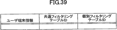
ユーザ端末情報と、共通フィルタリングテーブルIDと、個別フィルタリングテーブルIDとを管理する振分け管理テーブルと、
ユーザ端末が接続可能かを判断する認証サーバとの通信手段と、
ユーザと結び付けられた共通フィルタリングテーブルID、および個別フィルタリングテーブルIDを管理する識別子管理サーバとの通信手段と、
前記個別フィルタリングテーブルに書込まれるユーザ固有のセキュリティポリシとユーザとの関係を管理するセキュリティポリシ管理サーバとの通信手段とを備え、
前記ファイアウォール装置は、
ネットワーク接続開始時に、ユーザ端末から、ユーザ名を含む認証情報が付加された接続要求を受信し、当該ユーザ名を保持し、保持したユーザ名を認証サーバに通知し、
前記認証サーバから受信した認証応答に付随するユーザ端末情報を保持し、
前記ユーザ名を、前記識別子管理サーバと前記セキュリティポリシサーバに通知し、
前記識別子管理サーバから受信した共通フィルタリングテーブルID、および個別フィルタリングテーブルIDと、ユーザ端末情報とを対応付けて前記振分け管理テーブルに記述し、
前記セキュリティポリシサーバから受信したポリシ情報と、前記個別フィルタリングテーブルIDとを、前記個別フィルタリングテーブルに書込むファイアウォール装置により達成できる。
The third object is a firewall device that is installed between a plurality of user terminals and a network and performs packet filtering on a plurality of user terminals,
An individual filtering table that holds a security policy for each user,
A common filtering table that holds security policies common to multiple users;
A distribution management table for managing user terminal information, a common filtering table ID, and an individual filtering table ID;
Means for communicating with the authentication server to determine whether the user terminal is connectable;
Communication means with a common filtering table ID associated with a user and an identifier management server that manages the individual filtering table ID;
Communication means with a security policy management server that manages the relationship between the user-specific security policy written in the individual filtering table and the user,
The firewall device is
At the start of network connection, a connection request to which authentication information including a user name is added is received from the user terminal, the user name is held, the held user name is notified to the authentication server,
Holding user terminal information accompanying the authentication response received from the authentication server;
Notifying the user name to the identifier management server and the security policy server,
The common filtering table ID received from the identifier management server, the individual filtering table ID, and the user terminal information are associated and described in the distribution management table,
The policy information received from the security policy server and the individual filtering table ID can be achieved by a firewall device that writes the individual filtering table in the individual filtering table.
本発明によれば、ネットワークまたは端末の接続開始に合わせ必要なセキュリティポリシをロードすることが可能になる。 According to the present invention, it is possible to load a necessary security policy in accordance with the start of connection of a network or a terminal.
また、ネットワーク接続開始時にセキュリティポリシを書込む領域を示す識別子と、認証により接続開始するネットワークまたは端末に付与されるユーザ端末情報を結び付けておき、接続切断時に、切断するネットワークまたは端末のユーザ端末情報を元に、識別子を調べ、識別子に示される領域のセキュリティポリシを破棄するので、ネットワークまたは端末の接続切断に合わせセキュリティポリシを破棄することが可能になる。 In addition, an identifier indicating an area in which a security policy is written at the start of network connection is associated with user terminal information given to the network or terminal that starts connection by authentication, and the user terminal information of the network or terminal that is disconnected when connection is disconnected Thus, the identifier is checked, and the security policy in the area indicated by the identifier is discarded. Therefore, the security policy can be discarded in accordance with the disconnection of the network or the terminal.
また、本発明のファイアウォール装置は、セキュリティポリシを個別セキュリティポリシと、共通セキュリティポリシとに分け、共通セキュリティポリシは常にファイアウォール装置に保持しておき、個別セキュリティポリシのみを、ネットワークまたは端末の接続開始時にロードすることができるので、ロードするセキュリティポリシ量を軽減することが可能になる。 Further, the firewall device of the present invention divides security policies into individual security policies and common security policies, and the common security policy is always held in the firewall device, and only the individual security policy is used when the connection of the network or terminal is started. Since it can be loaded, the amount of security policy to be loaded can be reduced.
また、本発明のファイアウォール装置は、セキュリティポリシを配布する装置と、前述の識別子が調べられる装置を全てのファイアウォール装置と接続し、前述のセキュリティポリシのロードを行うことができるので、ネットワークまたは端末が収容されるファイアウォール装置を変更してネットワーク接続開始、あるいは切断を行っても、ファイアウォール装置は適切にセキュリティポリシをロードすることが可能になる。 Further, the firewall device of the present invention can connect the device that distributes the security policy and the device whose identifier can be checked to all the firewall devices, and can load the security policy described above. Even if the firewall device to be accommodated is changed and the network connection is started or disconnected, the firewall device can appropriately load the security policy.
以下、図面を参照して本発明の各実施例を説明する。 Embodiments of the present invention will be described below with reference to the drawings.
(実施例1−1〜実施例1−5)
[実施例1−1]
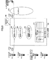
まず、本発明の実施例1−1を図8および図9を用いて説明する。本例では、ユーザからのネットワーク接続方式はPPP、認証用通信はRADIUSとする。
(Example 1-1 to Example 1-5)
[Example 1-1]
First, Example 1-1 of the present invention will be described with reference to FIGS. In this example, the network connection method from the user is PPP, and the authentication communication is RADIUS.
ファイアウォール装置100は、ユーザ毎に仮想ファイアウォールを具備している。例えば、ユーザ#aのセキュリティポリシが適用され、ユーザ#aの端末111を保護する仮想ファイアウォール102、ユーザ♯bのセキュリティポリシが適用され、ユーザ♯bの端末112を保護する仮想ファイアウォール103が、ファイアウォール装置100内に存在する。
The
また、振分け管理テーブル101には、事前に設定可能なユーザ名および仮想ファイアウォールIDが登録されている。すなわち振分け管理テーブル101には、ユーザ名#aと仮想ファイアウォールID102、ユーザ名♯bと仮想ファイアウォールID103との対応付けが登録されている。ただし、各ユーザ端末のユーザIDとなるユーザIPアドレスは未確定のため、この時点では登録することができない(振分け管理テーブル101−1の状態)。
In the distribution management table 101, user names and virtual firewall IDs that can be set in advance are registered. That is, in the distribution management table 101, associations between the user name #a and the
本例ではユーザ#aの端末111がインターネット110にネットワーク接続し、その後、接続相手端末113とIP通信を行うものとする。まず、ユーザ端末111からのネットワーク接続要求として、ユーザ端末111とファイアウォール装置100との間でLCP(Link Control Protocol)の情報がやりとりされる(139)。この後行われる認証情報のやりとり140により、ファイアウォール装置100はユーザ端末111から送信されるユーザ名#aを抽出し、ユーザ名#aを保持する(処理ポイント150)。
In this example, it is assumed that the
そして認証情報(ユーザ名およびパスワード)をRADIUSサーバ130に通知する(141)。RADIUSサーバ130にて認証され、その応答142を受信すると、ファイアウォール装置100はその応答142に記載されているユーザ端末に付与すべきユーザIPアドレスを保持する。このユーザIPアドレスを[a.a.a.a]とする。そして、ユーザ名#aを検索キーとして、振分け管理テーブル101の中のユーザ名が#aと記載されている行にこのユーザIPアドレス[a.a.a.a]を登録する(処理ポイント151。振分け管理テーブル101−2の状態)。
Then, the authentication information (user name and password) is notified to the RADIUS server 130 (141). When authenticated by the
また、ファイアウォール装置100は、これと同時に、NCP(Network Control Protocol)の情報をユーザ端末111とファイアウォール装置100との間でやりとりする(143)中で、ユーザIPアドレス[a.a.a.a]をユーザ端末111に送り、ユーザ端末111は自ユーザIPアドレスが[a.a.a.a]であると認識する。
At the same time, the
NCPが終了後、ユーザ端末とネットワークとの間でPPP接続が確立される。その後、ユーザ端末111から接続相手端末113に向け送信されるパケット121を、ファイアウォール装置100が受信すると、その送信元IPアドレスとして記載される[a.a.a.a]を検索キーとして振分け管理テーブル101を参照し、[a.a.a.a]の行に記載されている仮想ファイアウォールID=102を抽出し、該パケット121を仮想ファイアウォール102に振り分ける(処理ポイント152)。これにより、パケット121は、ユーザ#aが定めるセキュリティポリシに従うフィルタリングルールに従い、通過あるいは廃棄処理が適用される。
After the NCP ends, a PPP connection is established between the user terminal and the network. Thereafter, when the
また、通信相手端末113からユーザ端末111に向け送信されるパケット122をファイアウォール装置100が受信すると、その宛先IPアドレスとして記載される[a.a.a.a]を検索キーとして振分け管理テーブル101を参照し、[a.a.a.a]の行に記載されている仮想ファイアウォールID=102を抽出し、該パケット122を仮想ファイアウォール102に振り分ける(処理ポイント153)。これにより、パケット122は、ユーザ#aが定めるセキュリティポリシに従うフィルタリングルールに従い、通過あるいは廃棄処理が適用される。
When the
ユーザ♯bの端末112がインターネット110にネットワーク接続し、その後、接続相手端末113とIP通信を行う場合も、同様の手順により、端末112が送受信するパケットは仮想ファイアウォール103に振り分けられ、ユーザ♯bが定めるセキュリティポリシに従うフィルタリングルールに従い、通過あるいは廃棄処理が適用される。
When the
[実施例1−2]
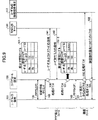
本発明の実施例1−2を、図10を用い説明する。本例は、実施例1−1において、ユーザ#aから送られるユーザ名あるいはパスワードに誤りがあるなどの理由により、ユーザ名およびパスワードの通知141によって送られたユーザ名とパスワードの組合せが、RADIUSサーバ130に登録されているユーザ名とパスワードの組合せと一致しない場合を示すものである。
[Example 1-2]
Example 1-2 of the present invention will be described with reference to FIG. In this example, the combination of the user name and the password sent by the user name and
なお、LCP139からユーザ名およびパスワードの通知141の処理は実施例1−1と同様であるため、説明を省略する。
Note that the processing of the user name and
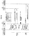
前述の理由により、RADIUSサーバ130からの認証エラー通知642が送られると、ファイアウォール装置100は、ユーザ端末111に認証エラー通知643を送信し、PPPの確立処理を終了する。このときファイアウォール装置100は、振分け管理テーブル101には何も処理を行わない。
For the above-described reason, when the
[実施例1−3]
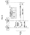
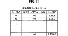
本発明の第3の実施例を、図8、図11および図12を用い説明する。本例は、実施例1−1において、ファイアウォールサービス未登録ユーザ♯cの端末114が、インターネット110にネットワーク接続し、その後、接続相手端末113とIP通信を行う形態を示すものである。なお、ファイアウォールサービス未登録ユーザ♯cは、振分け管理テーブル101−3には、ユーザ名および仮想ファイアウォールの登録はないが、端末114を通じてインターネット110への通信サービスは享受しており、RADIUSサーバ130にユーザ名およびパスワードが登録されている。
図12において、ユーザIPアドレスの通知142までの動作は、実施例1−1と同様であり、説明は省略する。
[Example 1-3]
A third embodiment of the present invention will be described with reference to FIGS. 8, 11 and 12. FIG. This example shows a mode in which the
In FIG. 12, the operations up to the user
ユーザIPアドレスの通知142を受信すると、ファイアウォール装置100はユーザIPアドレスの通知142に記載されているユーザ端末に付与すべきユーザIPアドレス[c.c.c.c]を保持する。そして、ユーザ名を検索キーとして、振分け管理テーブル101−3に対し、ユーザ名♯cの検索を行うが、ユーザ名♯cは存在しないため、ユーザIPアドレス[c.c.c.c]を振分け管理テーブル101−3には登録しない。
When the user
また、ファイアウォール装置100は、これと同時に、NCPの情報をユーザ端末114とファイアウォール装置100との間でやりとりする(143)中で、ユーザIPアドレス[c.c.c.c]をユーザ端末114に送り、ユーザ端末114は自ユーザIPアドレスが[c.c.c.c]であると認識する。
At the same time, the
NCPが終了後、ユーザ端末とネットワークとの間でPPP接続が確立される。その後、ユーザ端末114から接続相手端末113に向け送信されるパケット121を、ファイアウォール装置100が受信すると、その送信元IPアドレスとして記載される[c.c.c.c]を検索キーとして振分け管理テーブル101を参照した結果、該送信元IPアドレスが登録されていないことが判明する。
After the NCP ends, a PPP connection is established between the user terminal and the network. Thereafter, when the
該送信元IPアドレスが登録されていない場合、図11に示す振分け管理テーブル101−3の最下行にあるように、振り分けるべき仮想ファイアウォールは仮想ファイアウォール104と記載されているため、該パケット121を未登録ユーザ用の仮想ファイアウォール104に振り分ける(処理ポイント152)。
If the source IP address is not registered, the virtual firewall to be distributed is described as the
同様にして、通信相手端末113から送信されるパケット122に対しても、その宛先ユーザIPアドレス[c.c.c.c]を検索キーとして振分け管理テーブル101を参照した結果、該宛先IPアドレスが登録されていないことが判明すると、該パケット122を未登録ユーザ用の仮想ファイアウォール104に振り分ける(処理ポイント153)。
Similarly, for the
なお、未登録ユーザ用の仮想ファイアウォール104は、フィルタリングルールが記載されず、全てのパケットを無条件に通過させる、あるいは、未登録ユーザ全員に共通なフィルタリングルールが記載されている。
The
[実施例1−4]
本発明の第4の実施例を、図8、図13および図14を用い説明する。本例は、実施例1−3と同様の条件であり、ファイアウォールサービス未登録ユーザ♯cの端末114が、インターネット110にネットワーク接続し、その後、接続相手端末113とIP通信を行う形態を示すものである。なお、ファイアウォールサービス未登録ユーザ♯cは、振分け管理テーブル101−4には、ユーザ名および仮想ファイアウォールの登録はないが、端末114を通じてインターネット110への通信サービスは享受しており、RADIUSサーバ130にユーザ名およびパスワードが登録されている。
図14において、ユーザIPアドレスの通知142までの動作は、実施例1−1と同様であり、説明は省略する。
[Example 1-4]
A fourth embodiment of the present invention will be described with reference to FIGS. This example shows the same conditions as in Example 1-3, and shows a mode in which the
In FIG. 14, the operations up to the user
ユーザIPアドレスの通知142を受信すると、ファイアウォール装置100はユーザIPアドレスの通知142に記載されているユーザ端末に付与すべきユーザIPアドレス[c.c.c.c]を保持する。そして、ユーザ名を検索キーとして、振分け管理テーブル101−4に対し、ユーザ名♯cの検索を行うが、ユーザ名♯cは存在しない。ユーザ名が存在しない場合、図13に示すように、ユーザIPアドレス[c.c.c.c]および未登録ユーザ用の仮想ファイアウォール104のID=104を振分け管理テーブル101−4に登録する。
When the user
また、ファイアウォール装置100は、これと同時に、NCPの情報をユーザ端末114とファイアウォール装置100との間でやりとりする(143)中で、ユーザIPアドレス[c.c.c.c]をユーザ端末114に送り、ユーザ端末114は自ユーザIPアドレスが[c.c.c.c]であると認識する。
At the same time, the
NCPが終了後、ユーザ端末とネットワークとの間でPPP接続が確立される。その後、ユーザ端末114から接続相手端末113に向け送信されるパケット121を、ファイアウォール装置100が受信すると、その送信元IPアドレスとして記載される[c.c.c.c]を検索キーとして振分け管理テーブル101を参照し、該送信元IPアドレスと対応付けられている仮想ファイアウォールID=104を検索し、該パケット121を未登録ユーザ用の仮想ファイアウォール104に振り分ける(処理ポイント152)。
After the NCP ends, a PPP connection is established between the user terminal and the network. Thereafter, when the
同様にして、通信相手端末113から送信されるパケット122に対しても、その宛先ユーザIPアドレス[c.c.c.c]を検索キーとして振分け管理テーブル101−4を参照し、該送信宛先IPアドレスと対応付けられている仮想ファイアウォールID=104を検索し、該パケット122を未登録ユーザ用の仮想ファイアウォール104に振り分ける(処理ポイント153)。
Similarly, for the
なお、未登録ユーザ用の仮想ファイアウォール104は実施例1−3と同様、フィルタリングルールが記載されず、全てのパケットを無条件に通過させる、あるいは、未登録ユーザ全員に共通なフィルタリングルールが記載されている。
Note that the
また、該送信元IPアドレスが登録されていない場合、図13に示す振分け管理テーブル101−4の最下行にあるように、パケットを廃棄する。これによって、ある悪意ユーザがIP Spoofing攻撃などにより、どのユーザにも付与されていないIPアドレスを持つパケットを大量に送出した場合に、ファイアウォール装置100にてこれらのパケットを廃棄することができる。
If the source IP address is not registered, the packet is discarded as shown in the bottom row of the distribution management table 101-4 shown in FIG. Thus, when a malicious user sends a large number of packets having IP addresses not assigned to any user due to an IP spoofing attack or the like, the
[実施例1−5]
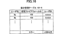
本発明の実施例1−5を、図8、図15および図16を用い説明する。本例は、実施例1−1において、ファイアウォールサービス未登録ユーザ♯dの端末115が、インターネット110にネットワーク接続し、その後、接続相手端末113とIP通信を行う形態を示すものである。なお、ユーザ♯dは本来、ファイアウォールサービスに登録されるべきユーザであるが、本例では、ファイアウォール装置100の管理者が振分け管理テーブル101−5にその登録をし忘れたあるいは誤った登録を行ったなどの理由により、ユーザ名♯dが振分け管理テーブル101−5に正しく登録されていない形態となっている。なお、RADIUSサーバ130には正しくユーザ名♯dおよびパスワードが登録されている。
図15において、ユーザIPアドレスの通知142までの動作は、実施例1−1と同様であり、説明は省略する。
[Example 1-5]
Example 1-5 of the present invention will be described with reference to FIGS. This example shows a form in which the
In FIG. 15, the operations up to the user
ユーザIPアドレスの通知142を受信すると、ファイアウォール装置100はユーザIPアドレスの通知142に記載されているユーザ端末に付与すべきユーザIPアドレス[d.d.d.d]を保持する。そして、ユーザ名を検索キーとして、振分け管理テーブル101−5に対し、ユーザ名♯dの検索を行うが、ユーザ名♯dは存在しない。ユーザ名が存在しない場合、ファイアウォール装置100は、ユーザ端末115に認証エラー通知943を送信し、PPPの確立処理を終了する。
Upon reception of the user
(実施例1−1〜1−5の効果)
実施例1−1のファイアウォール装置は、常時接続サービスのようにユーザIPアドレスが、ユーザ端末とネットワークとの接続が確立されるときに初めて付与され、かつ、ユーザIPアドレスの値が可変である場合に対し、動的に振分け管理テーブルにユーザIPアドレスを登録する手段を有する。また、本発明の動的ユーザ識別子対応ファイアウォール装置は、ユーザ毎に仮想ファイアウォールを有する。
(Effects of Examples 1-1 to 1-5)
The firewall device according to the embodiment 1-1 is provided with the user IP address for the first time when the connection between the user terminal and the network is established, and the value of the user IP address is variable as in the always-on service. On the other hand, there is means for dynamically registering the user IP address in the distribution management table. Moreover, the dynamic user identifier corresponding | compatible firewall apparatus of this invention has a virtual firewall for every user.
これにより、事前にユーザIPアドレスと仮想ファイアウォールIDとの対応付けができない通信形態に対し、ユーザ端末からのネットワーク接続のための認証情報を利用し、動的にユーザIPアドレスと仮想ファイアウォールIDとを対応づけ、該ユーザ端末が送信あるいは受信するパケットに対し、該ユーザが定めるセキュリティポリシに従うフィルタリングルールを適用することができる。また、収容ユーザの集約による経済化と、アウトソーシングによるユーザ稼動の軽減を可能とする。 As a result, for the communication mode in which the user IP address and the virtual firewall ID cannot be associated in advance, the authentication information for network connection from the user terminal is used, and the user IP address and the virtual firewall ID are dynamically set. It is possible to apply a filtering rule in accordance with the security policy determined by the user to the packet transmitted or received by the user terminal. In addition, it is possible to make the economy more efficient by consolidating accommodated users and to reduce user operations by outsourcing.
また、実施例1−2のファイアウォール装置は、ユーザから送られるユーザ名あるいはパスワードに誤りがあり、RADIUSサーバからの認証エラー通知が送られる場合に、振分け管理テーブルには何も処理を行わず、ユーザ端末に認証エラー通知を送信する。これにより、ネットワーク接続が拒絶される場合の振分け管理テーブル検索および登録処理を排除し、その分余った処理能力を、他の処理に注力することができる。 Further, the firewall device of the embodiment 1-2 does not perform any processing on the distribution management table when the user name or password sent from the user is incorrect and an authentication error notification is sent from the RADIUS server. An authentication error notification is transmitted to the user terminal. Thereby, the distribution management table search and registration processing when the network connection is rejected can be eliminated, and the remaining processing capacity can be focused on other processing.
また、実施例1−3および実施例1−4のファイアウォール装置は、ファイアウォールサービスを享受しないユーザのユーザ端末も収容することができ、本ファイアウォールサービスを享受しない各ユーザが、サービスを享受する度に発生する物理的な接続の収容替えの煩わしさを排除することができる。 Moreover, the firewall apparatus of Example 1-3 and Example 1-4 can also accommodate the user terminal of the user who does not enjoy a firewall service, and each user who does not enjoy this firewall service enjoys a service. The troublesomeness of changing the accommodation of the physical connection that occurs can be eliminated.
さらに、実施例1−3に示す手段の場合、未登録ユーザを振分け管理テーブルに登録させず、未登録ユーザの送受信パケットを自動的に未登録ユーザ用の仮想ファイアウォールに振り分けるため、振分け管理テーブルに登録される件数は、現在ネットワーク接続確立中の登録ユーザに限ることができ、検索時間の短縮に貢献する。 Furthermore, in the case of the means shown in the embodiment 1-3, the unregistered user is not registered in the distribution management table, and the transmission / reception packet of the unregistered user is automatically distributed to the virtual firewall for the unregistered user. The number of registrations can be limited to registered users who are currently establishing a network connection, which contributes to shortening the search time.
一方、実施例1−4に示す手段の場合、未登録ユーザを振分け管理テーブルに登録させ、未登録ユーザの送受信パケットを陽に未登録ユーザ用の仮想ファイアウォールに振分け、また、振分け管理テーブルに登録されていない場合は、パケットを廃棄するため、ある悪意ユーザがIP Spoofing攻撃などにより、どのユーザにも付与されていないIPアドレスを持つパケットを大量に送出した場合に、ファイアウォール装置にてこれらのパケットを廃棄することができる。 On the other hand, in the case of the means shown in the embodiment 1-4, the unregistered user is registered in the distribution management table, the transmission / reception packet of the unregistered user is explicitly distributed to the virtual firewall for the unregistered user, and is registered in the distribution management table. If a malicious user sends a large number of packets with IP addresses not assigned to any user due to an IP spoofing attack, etc., these packets are discarded by the firewall device. Can be discarded.
このように実施例1−3と実施例1−4の各手段は、用途により使い分けられる。 Thus, each means of Example 1-3 and Example 1-4 is used properly by a use.
実施例1−5のファイアウォール装置は、ファイアウォール装置の管理者が振分け管理テーブルに対し、ユーザ名および仮想ファイアウォールの登録をし忘れたあるいは誤った登録を行った場合に対し、セキュリティの観点から、もはや成立してはいけない通信を、強制的に終了させることが出来る。 In the firewall device of the embodiment 1-5, when the administrator of the firewall device forgets to register the user name and the virtual firewall in the distribution management table or performs incorrect registration, it is no longer in view of security. Communication that should not be established can be forcibly terminated.
(実施例2−1〜実施例2−7)
次に、実施例2−1〜実施例2−7について説明する。
(Example 2-1 to Example 2-7)
Next, Example 2-1 to Example 2-7 will be described.
実施例1−1等に示した動作により、事前にユーザIPアドレスと仮想ファイアウォールIDとの対応付けができない通信形態に対し、ユーザ端末からのネットワーク接続のための認証情報を利用し、動的にユーザIPアドレスと仮想ファイアウォールIDとを対応付け、該ユーザ端末が送信あるいは受信するパケットに対し、該ユーザが定めるセキュリティポリシに従うフィルタリングルールを適用することができる。 By using the authentication information for the network connection from the user terminal for the communication mode in which the user IP address and the virtual firewall ID cannot be associated in advance by the operation shown in the example 1-1 or the like, A user IP address and a virtual firewall ID are associated with each other, and a filtering rule according to a security policy defined by the user can be applied to a packet transmitted or received by the user terminal.
ただし、常時接続サービスの場合、データセンタ等への適用の場合と比較し、収容ユーザ数が断然に多い。 However, in the case of the always-on service, the number of accommodated users is far greater than in the case of application to a data center or the like.
想定される規模として、データセンタの場合、収容ユーザ数は数百〜数千であるのに対し、常時接続サービスの場合、収容ユーザ数は数万〜数十万規模となる。 As the assumed scale, the number of accommodated users is several hundred to several thousand in the case of a data center, whereas the number of accommodated users is several tens of thousands to several hundred thousand in the case of the always-on service.
現在、装置化され、サービスとして導入されている信頼性の高い仮想ファイアウォール装置の多くは、データセンタ向けに開発されており、実際に収容できるユーザ数は前述の通り、数百〜数千となっている。 Currently, many of the highly reliable virtual firewall devices that have been implemented as devices and have been introduced as services have been developed for data centers, and the actual number of users that can be accommodated is, as described above, hundreds to thousands. ing.
収容ユーザ数の規模は異なるものの、常時接続サービス向けの仮想ファイアウォール装置を開発するにあたり、開発の効率化や既存技術の活用の観点から、前記データセンタ向け仮想ファイアウォール装置を土台に流用開発や追加開発する手法が極めて有効となる。 Although the scale of the number of accommodated users is different, when developing a virtual firewall device for always-on services, development and additional development based on the virtual firewall device for data centers is used from the viewpoint of development efficiency and utilization of existing technologies. This technique is extremely effective.
したがって、常時接続サービス向けの仮想ファイアウォール装置を提供するための課題は、ユーザ多重数の向上にある。 Therefore, the problem for providing a virtual firewall device for always-on services is to improve the number of multiplexed users.
また、常時接続サービスではユーザ多重数が多いため、ユーザ毎に独立のセキュリティポリシを提供するサービス性を確保する場合、フィルタリングルールの合計数もユーザ多重数に比例し、多くなる。 In addition, since the always-on service has a large number of multiplexed users, when ensuring serviceability that provides an independent security policy for each user, the total number of filtering rules is also proportional to the number of multiplexed users.
しかし実際のところ、各ユーザのフィルタリングルールには、多くのユーザに共通するルールもあるため、ファイアウォール装置全体の観点から見た場合に、ルールの重複となり非効率である。その結果、フィルタリングテーブル量の増大に繋がる。 However, in fact, the filtering rules of each user include rules that are common to many users, so that when viewed from the perspective of the entire firewall apparatus, the rules overlap and are inefficient. As a result, the amount of filtering table increases.
以上のように常時接続サービス向けの仮想ファイアウォール装置を開発するには、ユーザ多重数の向上とフィルタリングテーブルの効率化が課題となる。 As described above, in order to develop a virtual firewall device for always-on services, improvement of the number of multiplexed users and efficiency of the filtering table are problems.
実施例2−1〜実施例2−7では、ユーザ多重数を向上させ、かつ、フィルタリングテーブルの効率化を実現するファイアウォール装置について説明する。 In Example 2-1 to Example 2-7, firewall devices that improve the number of multiplexed users and increase the efficiency of the filtering table will be described.
[実施例2−1]
図17は、本発明の実施例2−1のファイアウォール装置の概略構成を示すブロック図であり、図18は、本実施例の仮想ファイアウォール内のフィルタリングテーブルの構成を示す図である。
[Example 2-1]
FIG. 17 is a block diagram illustrating a schematic configuration of the firewall apparatus according to the embodiment 2-1 of the present invention, and FIG. 18 is a diagram illustrating a configuration of a filtering table in the virtual firewall according to the present embodiment.
なお、本実施例では、ユーザからのネットワーク接続方式はPPP(Point to point Protocol)、認証用通信はRADIUSとする。 In this embodiment, the network connection method from the user is PPP (Point to Point Protocol), and the authentication communication is RADIUS.
ファイアウォール装置300は、複数の仮想ファイアウォール(302,303,…,304)を具備する。
The
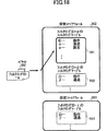
さらに、図18に示すように、各仮想ファイアウォール(302,303)には、それぞれ、フィルタリングIDによって特定される複数のフィルタリングテーブル(561,562,563)が存在し、各フィルタリングテーブル(561,562,563)には、各ユーザの独立した1つ以上のフィルタリングポリシが記載される。 Further, as shown in FIG. 18, each virtual firewall (302, 303) has a plurality of filtering tables (561, 562, 563) specified by the filtering ID, and each filtering table (561, 562). 563) describes one or more independent filtering policies for each user.
本実施例では、ユーザ#aとユーザ#bが定めるセキュリティポリシが仮想ファイアウォール302に、ユーザ#dが定めるセキュリティポリシが仮想ファイアウォール303に格納される。
In this embodiment, the security policy defined by the user #a and the user #b is stored in the
さらに、ユーザ#aは、仮想ファイアウォール302の中で、フィルタリングIDがαのフィルタリングテーブル561に、ユーザ#bはフィルタリングIDがβのフィルタリングテーブル562に、ユーザ#dは仮想ファイアウォール303の中で、フィルタリングIDがγのフィルタリングテーブル563に、それぞれのセキュリティポリシが記載されている。
Further, the user #a is filtered in the filtering table 561 whose filtering ID is α, the user #b is filtered in the filtering table 562 whose filtering ID is β, and the user #d is filtered in the
ここで、ユーザ#aとユーザ#bとを同じ仮想ファイアウォール302に収容するのは、例えば、ユーザ#aとユーザ#bの共通すべきフィルタリングポリシが同じである場合や、仮想ファイアウォールがインターネットプロバイダ毎に構築されており、ユーザ#aとユーザ#bとが同じインターネットプロバイダに属する場合、等の理由が挙げられる。
Here, the reason that the user #a and the user #b are accommodated in the same
振分け管理テーブル301には、事前に設定可能なユーザ名、仮想ファイアウォールIDおよびフィルタリングIDが登録されている。 In the distribution management table 301, user names, virtual firewall IDs, and filtering IDs that can be set in advance are registered.
すなわち、振分け管理テーブル301には、ユーザ名#a、仮想ファイアウォールID(302)およびフィルタリングID(α)の対応付け、ユーザ名#b、仮想ファイアウォールID(302)およびフィルタリングID(β)の対応付け、ユーザ名#d、仮想ファイアウォールID(303)およびフィルタリングID(γ)の対応付けが登録される。 That is, in the distribution management table 301, user name #a, virtual firewall ID (302) and filtering ID (α) are associated, and user name #b, virtual firewall ID (302) and filtering ID (β) are associated. , The association of the user name #d, the virtual firewall ID (303), and the filtering ID (γ) is registered.
ただし、各ユーザ端末のユーザIDとなるユーザIPアドレスは未確定のため、この時点では登録することができない(図19に示す振分け管理テーブル301−1の状態)。 However, since the user IP address serving as the user ID of each user terminal is not determined, it cannot be registered at this time (the state of the distribution management table 301-1 shown in FIG. 19).
ユーザIPアドレスが振分け管理テーブル301に登録されない限り、各ユーザからのパケットをそれぞれの仮想ファイアウォールに振分けること、フィルタリングIDの付与を行うことができない。 Unless the user IP address is registered in the distribution management table 301, it is impossible to distribute packets from each user to the respective virtual firewalls and to assign a filtering ID.
本実施例ではユーザ#aの端末311がインターネット310にネットワーク接続し、その後、接続相手端末313とIP通信を行うものとする。
In the present embodiment, it is assumed that the
以下、図19を用いて、本実施例のファイアウォール装置の動作について説明する。なお、図19は、本実施例のファイアウォール装置の動作を示すシーケンス図である。 Hereinafter, the operation of the firewall device of this embodiment will be described with reference to FIG. FIG. 19 is a sequence diagram showing the operation of the firewall device of this embodiment.
まず、ユーザ端末311からのネットワーク接続要求として、ユーザ端末311とファイアウォール装置300との間でLCP(Link Control Protocol)の情報がやりとりされる(図19の839)。
First, as a network connection request from the
この後行われる認証情報のやりとり(図19の840)により、ファイアウォール装置300は、ユーザ端末311から送信されるユーザ名#aを抽出し、ユーザ名#aを保持する(図19の処理ポイント850)。
Through the exchange of authentication information performed thereafter (840 in FIG. 19), the
そして認証情報(ユーザ名およびパスワード)を、RADIUSサーバ330に通知する(図19の841)。 Then, the authentication information (user name and password) is notified to the RADIUS server 330 (841 in FIG. 19).
RADIUSサーバ330にて認証され、その応答を受信すると(図19の842)、ファイアウォール装置300はその応答に記載されているユーザ端末に付与すべきユーザIPアドレスを保持する。このユーザIPアドレスを[a.a.a.a]とする。
When authenticated by the
そして、ユーザ名#aを検索キーとして、振分け管理テーブル301の中のユーザ名が#aと記載されている行に、このユーザIPアドレス[a.a.a.a]を登録する(図19の処理ポイント851、図19の振分け管理テーブル301−2の状態)。
Then, using the user name #a as a search key, the user IP address [a. a. a. a] is registered (the
また、ファイアウォール装置300は、これと同時に、NCP(Network Control Protocol)の情報をユーザ端末311とファイアウォール装置300との問でやりとりする(843)中で、ユーザIPアドレス[a.a.a.a]をユーザ端末311に送り、ユーザ端末311は自ユーザIPアドレスが[a.a.a.a]であると認識する。
At the same time, the
NCPが終了後、ユーザ端末311とインターネット310との間でPPP接続が確立される。
After the NCP ends, a PPP connection is established between the
その後、ユーザ端末311から接続相手端末313に向け送信されるパケット321を、ファイアウォール装置300が受信すると、その送信元IPアドレスとして記載される[a.a.a.a]を検索キーとして振分け管理テーブル(図19の301−2)を検索し、[a.a.a.a]の行に記載されている仮想ファイアウォールID(ID=302)、フィルタリングID(ID=α)を抽出し、当該パケット321を仮想ファイアウォール302に振り分けるとともに、当該パケット321に、αのフィルタリングIDを付与する(図19の処理ポイント852)。
After that, when the
フィルタリングIDを付与されたパケット322は、図18に示すように、振り分けられた仮想ファイアウォール302内において、フィルタリングIDがαのフィルタリングテーブル561に記載されているユーザ#aのセキュリティポリシに従うフィルタリングルールに従い、通過あるいは廃棄処理が適用される。
As shown in FIG. 18, the packet 322 to which the filtering ID is assigned follows the filtering rule according to the security policy of the user #a described in the filtering table 561 whose filtering ID is α in the distributed
また、通信相手端末313からユーザ端末311に向け送信されるパケット323をファイアウォール装置300が受信すると、その宛先IPアドレスとして記載される[a.a.a.a]を検索キーとして、振分け管理テーブル(図19の301−2)を検索し、[a.a.a.a]の行に記載されている仮想ファイアウォールID(ID=302)、フィルタリングID(ID=α)を抽出し、当該パケット323を仮想ファイアウォール302に振り分けるとともに、当該パケット323に、αのフィルタリングIDを付与する(図19の処理ポイント853)。
When the
フィルタリングIDを付与されたパケット324は、振り分けられた仮想ファイアウォール302内において、フィルタリングIDがαのフィルタリングテーブル561に記載されているユーザ#aのセキュリティポリシに従うフィルタリングルールに従い、通過あるいは廃棄処理が適用される。
The
ユーザ#bの端末312がインターネット310にネットワーク接続し、その後、接続相手端末313とIP通信を行う場合も、同様の手順により、端末312が送受信するパケットは仮想ファイアウォール302に振り分けられ、その後、フィルタリングテーブル562に記載されているユーザ#bのセキュリティポリシに従うフィルタリングルールに従い、通過あるいは廃棄処理が適用される。
Even when the
以上説明したように、本実施の形態では、フィルタリングID(α,β,γ)を導入することにより、各仮想ファイアウォール(302,303,304)に複数の独立したフィルタリングポリシを管理することができ、ユーザ多重数を向上させることができる。 As described above, in this embodiment, by introducing the filtering ID (α, β, γ), a plurality of independent filtering policies can be managed in each virtual firewall (302, 303, 304). The number of multiplexed users can be improved.
また、ユーザ毎のパケットの検索範囲は、付与されたフィルタリングIDの値と一致するテーブルのみを検索対象とするため、検索処理時間が不必要に長くなるのを抑制することができる。 In addition, since the search range of the packet for each user is a search target only for a table that matches the value of the assigned filtering ID, it is possible to suppress an unnecessarily long search processing time.
[実施例2−2]
本発明の実施例2−2のファイアウォール装置は、仮想ファイアウォールを備えていない点で、前述の実施例2−1のファイアウォール装置と相異する。
[Example 2-2]
The firewall device according to the embodiment 2-2 of the present invention is different from the firewall device according to the embodiment 2-1 in that it does not include a virtual firewall.
以下、本実施例のファイアウォール装置について、前述の実施例2−1のファイアウォール装置との相異点を中心に説明する。 Hereinafter, the firewall device of the present embodiment will be described focusing on differences from the firewall device of the above-described embodiment 2-1.
なお、実施例においても、ユーザからのネットワーク接続方式はPPP、認証用通信はRADIUSとする。 In the embodiment as well, the network connection method from the user is PPP, and the authentication communication is RADIUS.
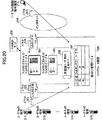
図20は、本発明の実施例2−2のファイアウォール装置の概略構成を示すブロック図である。 FIG. 20 is a block diagram illustrating a schematic configuration of the firewall apparatus according to the embodiment 2-2 of the present invention.
図20に示すように、本実施例のファイアウォール装置300は、フィルタリングIDによって特定される複数のフィルタリングテーブル(561,562)を有し、各フィルタリングテーブルには、各ユーザの独立したフィルタリングポリシが記載される。
As shown in FIG. 20, the
本実施例では、ユーザ#aはフィルタリングIDがαのフィルタリングテーブル561に、ユーザ#bはフィルタリングIDがβのフィルタリングテーブル562に、それぞれのセキュリティポリシが記載されている。 In this embodiment, the security policy is described in the filtering table 561 whose filtering ID is α for the user #a, and in the filtering table 562 whose filtering ID is β for the user #b.
振分け管理テーブル301には、事前に設定可能なユーザ名およびフィルタリングIDが登録されている。 In the distribution management table 301, user names and filtering IDs that can be set in advance are registered.
すなわち振分け管理テーブル301には、ユーザ名#aおよびフィルタリングID αの対応付け、ユーザ名#bおよびフィルタリングID
βの対応付けが登録される。
That is, in the distribution management table 301, the association between the user name #a and the filtering ID α, the user name #b and the filtering ID
Correspondence of β is registered.
ただし、各ユーザ端末のユーザIDとなるユーザIPアドレスは未確定のため、この時点では登録することができない(図21に示す振分け管理テーブル301−1の状態)。 However, since the user IP address serving as the user ID of each user terminal is not determined, it cannot be registered at this time (the state of the distribution management table 301-1 shown in FIG. 21).
ユーザIPアドレスが振分け管理テーブル301に登録されない限り、各ユーザからのパケットに対し、フィルタリングIDの付与を行うことができない。 Unless the user IP address is registered in the distribution management table 301, a filtering ID cannot be assigned to a packet from each user.
本実施例ではユーザ#aの端末311がインターネット310にネットワーク接続し、その後、接続相手端末313とIP通信を行うものとする。
In the present embodiment, it is assumed that the
以下、図21を用いて、本実施例のファイアウォール装置の動作について説明する。なお、図21は、本実施例のファイアウォール装置の動作を示すシーケンス図である。 Hereinafter, the operation of the firewall device of the present embodiment will be described with reference to FIG. FIG. 21 is a sequence diagram showing the operation of the firewall device of this embodiment.
ユーザ端末311とファイアウォール装置300との間でのLCPの情報のやりとり(図21の839)から、ユーザ端末311とファイアウォール装置300との間でのNCPの情報をやりとり(図21の843)までの動作は、実施例2−1と同様であるので、再度の説明は省略する。
From the exchange of LCP information between the
NCPが終了後、ユーザ端末311とインターネット310との間でPPP接続が確立される。その後、ユーザ端末311から接続相手端末313に向け送信されるパケット321を、ファイアウォール装置300が受信すると、その送信元IPアドレスとして記載される[a.a.a.a]を検索キーとして振分け管理テーブル(図21の301−2)を検索し、[a.a.a.a]の行に記載されているフィルタリングID(ID=α)を抽出し、当該パケット321に対し、αのフィルタリングIDを付与する(図21の処理ポイント852)。
After the NCP ends, a PPP connection is established between the
フィルタリングIDを付与されたパケット322は、フィルタリングIDがαのフィルタリングテーブル561に記載されているユーザ#aのセキュリティポリシに従うフィルタリングルールに従い、通過あるいは廃棄処理が適用される。 The packet 322 to which the filtering ID is assigned is subjected to a passing or discarding process according to the filtering rule according to the security policy of the user #a described in the filtering table 561 whose filtering ID is α.
また、通信相手端末313からユーザ端末311に向け送信されるパケット323をファイアウォール装置300が受信すると、その宛先IPアドレスとして記載される[a.a.a.a]を検索キーとして振分け管理テーブル(図21の301−2)を検索し、[a.a.a.a]の行に記載されているフィルタリングID(ID=α)を抽出し、当該パケット323に対して、αのフィルタリングIDを付与する(図21の処理ポイント853)。
When the
フィルタリングIDを付与されたパケット324は、フィルタリングIDがαのフィルタリングテーブル561に記載されているユーザ#aのセキュリティポリシに従うフィルタリングルールに従い、通過あるいは廃棄処理が適用される。
The
ユーザ#bの端末312がインターネット310にネットワーク接続し、その後、接続相手端末313とIP通信を行う場合も、同様の手順により、端末312が送受信するパケットはフィルタリングテーブル562に記載されているユーザ#bのセキュリティポリシに従うフィルタリングルールに従い、通過あるいは廃棄処理が適用される。
When the
[実施例2−3]
本発明の実施例2−3のファイアウォール装置は、フィルタリングIDを、個別フィルタリングIDと共通フィルタリングIDに2分化した点で、前述の実施例2−1のファイアウォール装置と相異する。
[Example 2-3]
The firewall apparatus according to the embodiment 2-3 of the present invention differs from the firewall apparatus according to the embodiment 2-1 in that the filtering ID is divided into an individual filtering ID and a common filtering ID.
以下、本実施例のファイアウォール装置について、前述の実施例2−1のファイアウォール装置との相違点を中心に説明する。 Hereinafter, the firewall device of the present embodiment will be described focusing on differences from the firewall device of the above-described embodiment 2-1.
なお、本実施例2−3のファイアウォール装置の概略構成は、図17と同じである。また、本実施例においても、ユーザからのネットワーク接続方式はPPP、認証用通信はRADIUSとする。 Note that the schematic configuration of the firewall device of the embodiment 2-3 is the same as that shown in FIG. Also in this embodiment, the network connection method from the user is PPP, and the authentication communication is RADIUS.
本実施例のファイアウォール装置では、前述の実施例2−1のフィルタリングIDを、さらに個別フィルタリングIDと共通フィルタリングIDに2分化し、各ユーザ個別のフィルタリングポリシは個別フィルタリングテーブルに記載し、複数のユーザにて共通化することが可能なフィルタリングポリシは共通フィルタリングテーブルに記載する。 In the firewall device of the present embodiment, the filtering ID of the above-described embodiment 2-1 is further divided into an individual filtering ID and a common filtering ID, and each user's individual filtering policy is described in an individual filtering table, and a plurality of users Filtering policies that can be made common in are described in the common filtering table.
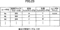
したがって、本実施例において、図17に示す振分け管理テーブル301および図19に示す振分け管理テーブル(301−1)は、図22に示す振分け管理テーブル601に置き換えられ、図19に示す振分け管理テーブル(301−2)は、図23の振分け管理テーブル1101に置き換えられる。 Therefore, in this embodiment, the distribution management table 301 shown in FIG. 17 and the distribution management table (301-1) shown in FIG. 19 are replaced with the distribution management table 601 shown in FIG. 301-2) is replaced with the distribution management table 1101 of FIG.
また、図24は、本実施例のファイアウォール装置の仮想ファイアウォール内のフィルタリングテーブルの構成を示す図である。 FIG. 24 is a diagram illustrating a configuration of a filtering table in the virtual firewall of the firewall apparatus according to the present embodiment.
本実施の形態のファイアウォール装置300は、複数の仮想ファイアウォール(302,303,…,304)を具備している。
The
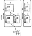
さらに、図24に示すように、各仮想ファイアウォール(302,303)にはそれぞれ、個別フィルタリングIDによって特定される複数のフィルタリングテーブル(561,562,563)、および共通フィルタリングIDによって特定される複数のフィルタリングテーブル(571,572)が存在する。 Furthermore, as shown in FIG. 24, each virtual firewall (302, 303) has a plurality of filtering tables (561, 562, 563) specified by individual filtering IDs and a plurality of filtering tables specified by common filtering IDs. There is a filtering table (571, 572).
各ユーザ個別のフィルタリングポリシは個別フィルタリングテーブル(561,562,563)に、複数のユーザにて共通化することが可能なフィルタリングポリシは共通フィルタリングテーブル(571,572)に記載されている。 The filtering policy for each user is described in the individual filtering table (561, 562, 563), and the filtering policy that can be shared by a plurality of users is described in the common filtering table (571, 572).
また、これに伴い、図22に示すように振分け管理テーブル601は、ユーザ名、仮想ファイアウォールID、個別フィルタリングIDおよび共通フィルタリングIDを管理する。 Accordingly, as shown in FIG. 22, the distribution management table 601 manages user names, virtual firewall IDs, individual filtering IDs, and common filtering IDs.
本実施例では、ユーザ#aとユーザ#bが定めるセキュリティポリシが仮想ファイアウォール302に、ユーザ#dが定めるセキュリティポリシが仮想ファイアウォール303に格納されており、さらに、ユーザ#aの個別フィルタリングポリシは仮想ファイアウォール302の中で、フィルタリングIDがαの個別フィルタリングテーブル561に、ユーザ#bの個別フィルタリングポリシはフィルタリングIDがβの個別フィルタリングテーブル562に、ユーザ#dの個別フィルタリングポリシは仮想ファイアウォール303の中で、フィルタリングIDがγの個別フィルタリングテーブル563に、それぞれ記載されている。
In this embodiment, the security policy defined by the user #a and the user #b is stored in the
また、ユーザ#aとユーザ#bは、フィルタリングIDがIの共通フィルタリングテーブル571に記載のフィルタリングポリシも適用される。 The filtering policy described in the common filtering table 571 whose filtering ID is I is also applied to the user #a and the user #b.
同様に、ユーザ#dは、フィルタリングIDがIIの共通フィルタリングテーブル572に記載のフィルタリングポリシも適用される。 Similarly, the filtering policy described in the common filtering table 572 whose filtering ID is II is also applied to the user #d.
振分け管理テーブル601には、事前に設定可能なユーザ名、仮想ファイアウォールID、個別フィルタリングIDおよび共通フィルタリングIDが登録されている。 In the distribution management table 601, user names, virtual firewall IDs, individual filtering IDs, and common filtering IDs that can be set in advance are registered.
すなわち振分け管理テーブル601には、ユーザ名#a、仮想ファイアウォールID(302)、個別フィルタリングID(α)および共通フィルタリングID(I)の対応付け、ユーザ名#b、仮想ファイアウォールID(302)、個別フィルタリングID(β)および共通フィルタリングID(I)の対応付け、ユーザ名#d、仮想ファイアウォールID(303)、個別フィルタリングID(γ)および共通フィルタリングID(II)の対応付けが登録される。 That is, in the distribution management table 601, the user name #a, the virtual firewall ID (302), the individual filtering ID (α) and the common filtering ID (I) are associated, the user name #b, the virtual firewall ID (302), the individual Correspondence between filtering ID (β) and common filtering ID (I), user name #d, virtual firewall ID (303), individual filtering ID (γ), and common filtering ID (II) are registered.
ただし、各ユーザ端末のユーザIDとなるユーザIPアドレスは未確定のため、この時点では登録することができない(図22の振分け管理テーブル601の状態)。 However, since the user IP address serving as the user ID of each user terminal is not determined, it cannot be registered at this point (the state of the distribution management table 601 in FIG. 22).
ユーザIPアドレスが振分け管理テーブル601に登録されない限り、各ユーザからのパケットをそれぞれの仮想ファイアウォールに振分けること、個別フィルタリングIDおよび共通フィルタリングIDの付与を行うことができない。 Unless the user IP address is registered in the distribution management table 601, the packets from each user cannot be distributed to the respective virtual firewalls, and the individual filtering ID and the common filtering ID cannot be assigned.
本実施例では、ユーザ#aの端末311がインターネット310にネットワーク接続し、その後、接続相手端末313とIP通信を行うものとする。
In this embodiment, it is assumed that the
以下、図19を用いて、本実施例のファイアウォール装置の動作について説明する。 Hereinafter, the operation of the firewall device of this embodiment will be described with reference to FIG.
ユーザ端末311とファイアウォール装置300との間でのLCPの情報のやりとりから、ユーザ端末311とファイアウォ一ル装置300との間でのNCPの情報をやりとりまでの動作は、実施例2−1と同様であるので、再度の説明は省略する。
The operations from the exchange of LCP information between the
NCPが終了後、ユーザ端末311とインターネット310との問でPPP接続が確立される。その後、図17に示すように、ユーザ端末311から接続相手端末313に向け送信されるパケット321をファイアウォール装置300が受信すると、その送信元IPアドレスとして記載される[a.a.a.a]を検索キーとして振分け管理テーブル1101を検索し、[a.a.a.a]の行に記載されている仮想ファイアウォールID(ID=302)、個別フィルタリングID(ID=α)および共通フィルタリングID(ID=I)を抽出し、当該パケット321を仮想ファイアウォール302に振り分けるとともに、αの個別フィルタリングID、およびIの共通フィルタリングIDを付与する(図19の処理ポイント852)。
After the NCP is finished, a PPP connection is established between the
個別フィルタリングIDおよび共通フィルタリングIDが付与されたパケット322は、図24に示すように、仮想ファイアウォール302内において、個別フィルタリングIDがαの個別フィルタリングテーブル561に記載されたユーザ#aのセキュリティポリシに従うフィルタリングルールに従い、通過あるいは廃棄処理が行われる。
As shown in FIG. 24, the packet 322 to which the individual filtering ID and the common filtering ID are assigned is filtered according to the security policy of the user #a described in the individual filtering table 561 whose individual filtering ID is α in the
もし個別フィルタリングテーブル561に記載のフィルタリングポリシに、適用すべきルールが存在しなかった場合、パケット322は、次に、共通フィルタリングIDがIの共通フィルタリングテーブル571に記載されたフィルタリングポリシに従い、通過あるいは廃棄処理が行われる。 If there is no rule to be applied to the filtering policy described in the individual filtering table 561, the packet 322 is passed or filtered according to the filtering policy described in the common filtering table 571 whose common filtering ID is I. A disposal process is performed.
また、通信相手端末313からユーザ端末311に向け送信されるパケット323をファイアウォール装置300が受信すると、その宛先IPアドレスとして記載される[a.a.a.a]を検索キーとして振分け管理テーブル1101を検索し、[a.a.a.a]の行に記載されている仮想ファイアウォールID(ID=302)、個別フィルタリングID(ID=α)および共通フィルタリングID(ID=I)を抽出し、当該パケット323を仮想ファイアウォール302に振り分けるとともに、αの個別フィルタリングIDおよびIの共通フィルタリングIDを付与する(図19の処理ポイント853)。
When the
個別フィルタリングIDおよび共通フィルタリングIDが付与されたパケット324は、個別フィルタリングIDがαの個別フィルタリングテーブル561に記載されたユーザ#aのセキュリティポリシに従うフィルタリングルールに従い、通過あるいは廃棄処理が行われる。
The
もし個別フィルタリングテーブル561に記載されたフィルタリングポリシに、適用すべきルールが存在しなかった場合、パケット324は、次に、共通フィルタリングIDがIの共通フィルタリングテーブル571に記載されたフィルタリングポリシに従い、通過あるいは廃棄処理が行われる。
If there is no rule to be applied to the filtering policy described in the individual filtering table 561, the
以上説明したように、本実施例によれば、例えば、10ユーザが2つの同じフィルタリングルールを利用している場合、従来技術を適用すると、合計20ルールがフィルタリングテーブルに記載されるのに対し、本実施例では、2ルールのみフィルタリングテーブルに記載すればよいことになる。 As described above, according to the present embodiment, for example, when 10 users are using the same two filtering rules, when the conventional technique is applied, a total of 20 rules are described in the filtering table. In this embodiment, only two rules need be described in the filtering table.
すなわち、共通フィルタリングIDおよび共通フィルタリングテーブルの導入により、フィルタリングポリシを効率的に管理することが可能となる。 That is, by introducing the common filtering ID and the common filtering table, it becomes possible to efficiently manage the filtering policy.
なお、実施例2−2における仮想ファイアウォールを用いない形態においても、本実施例における個別フィルタリングテーブル、共通フィルタリングテーブルを導入することが可能である。その場合、実施例2−2において、フィルタリングIDに代えて、振り分け管理テーブルに本実施例と同様の個別フィルタリングIDと共通フィルタリングIDを設け、また、フィルタリングテーブルに代えて、本実施例と同様の個別フィルタリングテーブルと共通フィルタリングテーブルを備える。 Even in a mode that does not use the virtual firewall in the embodiment 2-2, it is possible to introduce the individual filtering table and the common filtering table in the present embodiment. In that case, in the example 2-2, instead of the filtering ID, the distribution management table is provided with the same individual filtering ID and the common filtering ID as in this example, and the same as in this example instead of the filtering table. An individual filtering table and a common filtering table are provided.
[実施例2−4]
本実施例のファイアウォール装置は、前述の実施例2−1、2−2のファイアウォール装置において、ユーザ#aから送られるユーザ名あるいはパスワードに誤りがあるなどの理由により、ユーザ名およびパスワードの通知によって送られたユーザ名とパスワードの組合せが、RADIUSサ一バ330に登録されているユーザ名とパスワードの組合せと一致しない場合の実施の形態である。
[Example 2-4]
The firewall device of the present embodiment is the same as that of the above-described firewall devices of Embodiments 2-1 and 2-2, by the notification of the user name and password because the user name or password sent from the user #a is incorrect. In this embodiment, the combination of the user name and password sent does not match the combination of the user name and password registered in the
実施例2−4のファイアウォール装置の動作を、図25を用いて説明する。なお、図25は、実施例2−4のファイアウォール装置の動作を示すシーケンス図である。 The operation of the firewall device of the embodiment 2-4 will be described with reference to FIG. FIG. 25 is a sequence diagram illustrating the operation of the firewall device of the embodiment 2-4.
また、LCP(図25の339)からユーザ名およびパスワードの通知(図25の341)の処理は、実施例2−1と同様であるので、再度の説明は省略する。 Further, the process of notification of the user name and password (341 in FIG. 25) from the LCP (339 in FIG. 25) is the same as that in the embodiment 2-1, and thus the description thereof will be omitted.
前述の理由により、RADIUSサーバ330へのユーザ名およびパスワードの通知(図25の341)に対する応答として、RADIUSサーバ330からの認証エラー通知が送られると(図25の1242)、ファイアウォール装置300は、ユーザ端末311に認証エラー通知を送信し(図25の1243)、PPPの確立処理を終了する。
For the above-described reason, when an authentication error notification is sent from the RADIUS server 330 (1242 in FIG. 25) as a response to the user name and password notification (341 in FIG. 25) to the
このときファイアウォール装置300は、振分け管理テーブル301には何も処理を行わない。
At this time, the
[実施例2−5]
本発明の実施例2−5のファイアウォール装置は、前述の実施例2−1のファイアウォール装置において、ファイアウォールサービス未登録ユーザ#cの端末314が、インターネット310にネットワーク接続し、その後、接続相手端末313とIP通信を行う形態の実施の形態である。
[Example 2-5]
The firewall device according to Embodiment 2-5 of the present invention is the same as the firewall device according to Embodiment 2-1 described above, except that the
本実施例2−5のファイアウォール装置の概略構成は、図17と同じであり、図26は、本実施例の振分け管理テーブルの内容を示す図である。 The schematic configuration of the firewall device of the second embodiment is the same as that of FIG. 17, and FIG. 26 is a diagram showing the contents of the distribution management table of the present embodiment.
なお、ファイアウォールサービス未登録ユーザ#cは、振分け管理テーブル(301−3)には、ユーザ名および仮想ファイアウォールの登録はないが、端末314を通じてインターネット310への通信サービスは享受しており、RADIUSサーバ330にユーザ名およびパスワードが登録されている。
The firewall service unregistered user #c does not register the user name and virtual firewall in the distribution management table (301-3), but enjoys the communication service to the
以下、図27を用いて、本実施例のファイアウォール装置の動作について説明する。なお、図27は、本実施例のファイアウォール装置の動作を示すシーケンス図である。 Hereinafter, the operation of the firewall device of the present embodiment will be described with reference to FIG. FIG. 27 is a sequence diagram showing the operation of the firewall device of this embodiment.
図27において、LCP(図27の339)から、ユーザIPアドレスの通知(図27の342)までの動作は、実施例2−1と同じであるので、再度の説明は省略する。 In FIG. 27, the operation from LCP (339 in FIG. 27) to notification of the user IP address (342 in FIG. 27) is the same as that in the embodiment 2-1, and thus the description thereof is omitted.
ユーザIPアドレスの通知(図27の342)を受信すると、ファイアウォール装置300は、ユーザIPアドレスの通知に記載されているユーザ端末に付与すべきユーザIPアドレス[c.c.c.c]を保持する。
When the notification of the user IP address (342 in FIG. 27) is received, the
そして、ユーザ名を検索キーとして、振分け管理テーブル(301−3)に対し、ユーザ名#cの検索を行うが、ユーザ名#cは存在しないため、ユーザIPアドレス[c.c.c.c]を振分け管理テーブル(301−3)には登録しない。 Then, the user name #c is searched for the distribution management table (301-3) using the user name as a search key. Since the user name #c does not exist, the user IP address [c. c. c. c] is not registered in the distribution management table (301-3).
また、ファイアウォール装置300は、これと同時に、NCPの情報をユーザ端末314とファイアウォール装置300との間でやりとりする(図27の343)中で、ユーザIPアドレス[c.c.c.c]をユーザ端末314に送り、ユーザ端末314は自ユーザIPアドレスが[c.c.c.c]であると認識する。
At the same time, the
NCPが終了後、ユーザ端末314とインターネット310との間でPPP接続が確立される。その後、ユーザ端末314から接続相手端末313に向け送信されるパケット321を、ファイアウォール装置300が受信すると、その送信元IPアドレスとして記載される[c.c.c.c]を検索キーとして振分け管理テーブル(301−3)を検索した結果、該送信元IPアドレスが登録されていないことが判明する。
After NCP ends, a PPP connection is established between the
該送信元IPアドレスが登録されていない場合、図26に示す振分け管理テーブル(301−3)の最下行にあるように、振分けるべき仮想ファイアウォールは仮想ファイアウォール304と記載されているため、該パケット321を未登録ユーザ用の仮想ファイァウォール304に振り分ける(図27の処理ポイント352)。
If the source IP address is not registered, the virtual firewall to be distributed is described as the
同様にして、通信相手端末313から送信されるパケット323に対しても、その宛先ユーザIPアドレス[c.c.c.c]を検索キーとして振分け管理テーブル(301−3)を検索した結果、該宛先IPアドレスが登録されていないことが判明すると、当該パケット323を未登録ユーザ用の仮想ファイアウォール304に振り分ける(図27の処理ポイント353)。
Similarly, for the
なお、未登録ユーザ用の仮想ファイアウォール304は、フィルタリングルールが記載されず、全てのパケットを無条件に通過させる、あるいは、未登録ユーザ全員に共通なフィルタリングルールが記載されている。
The
なお、本実施例のファイアウォール装置は、前述の実施例2−2のファイアウォール装置にも適用可能である。この場合に、ファイアウォールサービス未登録ユーザ#cの端末314からのパケット、ファイアウォールサービス未登録ユーザ#cの端末314宛のパケットは、図20に示す迂回ルート305を通過する。
Note that the firewall device of the present embodiment is also applicable to the firewall device of the above-described embodiment 2-2. In this case, a packet from the
[実施例2−6]
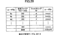
本発明の実施例2−6のファイアウォール装置は、前述の実施例2−5のファイアウォール装置と同様の条件であり、ファイアウォールサービス未登録ユーザ#cの端末314が、インターネット310にネットワーク接続し、その後、接続相手端末313とIP通信を行う形態である。
[Example 2-6]
The firewall device of the embodiment 2-6 of the present invention has the same conditions as the firewall device of the embodiment 2-5 described above, and the
本実施例のファイアウォール装置の概略構成は、図17と同じであり、図28は、本実施例の振分け管理テーブルの内容を示す図である。 The schematic configuration of the firewall device of this embodiment is the same as that of FIG. 17, and FIG. 28 is a diagram showing the contents of the distribution management table of this embodiment.
なお、ファイアウォールサービス未登録ユーザ#cは、振分け管理テーブル(301−4)には、ユーザ名および仮想ファイアウォールの登録はないが、端末314を通じてインターネット310への通信サービスは享受しており、RADIUSサーバ330にユーザ名およびパスワードが登録されている。
The firewall service unregistered user #c does not register the user name and the virtual firewall in the distribution management table (301-4), but enjoys the communication service to the
以下、図29を用いて、本実施例のファイアウォール装置の動作について説明する。なお、図29は、本実施例のファイアウォール装置の動作を示すシーケンス図である。 Hereinafter, the operation of the firewall apparatus according to the present embodiment will be described with reference to FIG. FIG. 29 is a sequence diagram showing the operation of the firewall device of this embodiment.
図29において、LCP(図29の339)から、ユーザIPアドレスの通知(図29の342)までの動作は、実施例2−1と同じであるので、再度の説明は省略する。 In FIG. 29, the operations from LCP (339 in FIG. 29) to user IP address notification (342 in FIG. 29) are the same as those in the embodiment 2-1, and thus the description thereof will be omitted.
ユーザIPアドレスの通知(図29の342)を受信すると、ファイアウォール装置300は、ユーザIPアドレスの通知に記載されているユーザ端末に付与すべきユーザIPアドレス[c.c.c.c]を保持する。
When the notification of the user IP address (342 in FIG. 29) is received, the
そして、ユーザ名を検索キーとして、振分け管理テーブル(301−4)に対し、ユーザ名#cの検索を行うが、ユーザ名#cは存在しない。 Then, the user name #c is searched for the distribution management table (301-4) using the user name as a search key, but the user name #c does not exist.
ユーザ名が存在しない場合、図28に示すように、ユーザIPアドレス[c.c.c.c]および未登録ユーザ用の仮想ファイアウォール304のID(ID=304)を振分け管理テーブル(301−4)に登録する。
If the user name does not exist, the user IP address [c. c. c. c] and the ID (ID = 304) of the
また、ファイアウォール装置300は、これと同時に、NCPの情報をユーザ端末314とファイアウォール装置300との間でやりとりする(図29の343)中で、ユーザIPアドレス[c.c.c.c]をユーザ端末314に送り、ユーザ端末314は自ユーザIPアドレスが[c.c.c.c]であると認識する。
At the same time, the
NCPが終了後、ユーザ端末314とインターネット310との間でPPP接続が確立される。その後、ユーザ端末314から接続相手端末313に向け送信されるパケット321を、ファイアウォール装置300が受信すると、その送信元IPアドレスとして記載される[c.c.c.c]を検索キーとして振分け管理テーブル(301−4)を検索し、当該送信元IPアドレスと対応付けられている仮想ファイアウォールID(ID=304)を抽出し、当該パケット321を未登録ユーザ用の仮想ファイアウォール304に振り分ける(図29の処理ポイント352)。
After NCP ends, a PPP connection is established between the
同様にして、通信相手端末313から送信されるパケット323に対しても、その宛先ユーザIPアドレス[c.c.c.c]を検索キーとして振分け管理テーブル(301−4)を検索し、当該送信先IPアドレスと対応付けられている仮想ファイアウォールID(ID=304)を抽出し、当該パケット323を未登録ユーザ用の仮想ファイアウォール304に振り分ける(図29の処理ポイント353)。
Similarly, for the
なお、未登録ユーザ用の仮想ファイアウォール304は、前述の実施例2−5と同様、フィルタリングルールが記載されず、全てのパケットを無条件に通過させる、あるいは、未登録ユーザ全員に共通なフィルタリングルールが記載されている。
Note that the
また、送信元IPアドレスが登録されていない場合、図28に示す振分け管理テーブル3014の最下行にあるように、パケットを廃棄する。 If the source IP address is not registered, the packet is discarded as shown in the bottom row of the distribution management table 3014 shown in FIG.
これよって、ある悪意ユーザがIP Spoofing攻撃などにより、どのユーザにも付与されていないIPアドレスを持つパケットを大量に送出した場合に、ファイアウォール装置300にてこれらのパケットを廃棄することができる。
Accordingly, when a malicious user sends a large number of packets having IP addresses not assigned to any user due to an IP spoofing attack or the like, the
なお、本実施例のファイアウォール装置は、前述の実施例2−2のファイアウォール装置にも適用可能である。 Note that the firewall device of the present embodiment is also applicable to the firewall device of the above-described embodiment 2-2.
この場合に、振分け管理テーブル(301−4)には、ユーザIPアドレス[c.c.c.c]および未登録ユーザ用のフィルタリングIDを登録する。そして、ファイアウォールサービス未登録ユーザ#cの端末314からのパケット、ファイアウォールサービス未登録ユーザ#cの端末314宛のパケットは、図20に示す迂回ルート305を通過する。
In this case, the distribution management table (301-4) includes a user IP address [c. c. c. c] and the filtering ID for unregistered users. Then, the packet from the
[実施例2−7]
本発明の実施例2−7のファイアウォール装置は、前述の実施例2−1のファイアウォール装置において、ファイアウォールサービス未登録ユーザ#dの端末315が、インターネット310にネットワーク接続し、その後、接続相手端末313とIP通信を行う形態を示すものである。
[Example 2-7]
The firewall apparatus according to Embodiment 2-7 of the present invention is the same as the firewall apparatus according to Embodiment 2-1, except that the
本実施例のファイアウォール装置の概略構成は、図17と同じであり、図30は、本実施例の振分け管理テーブルの内容を示す図である。 The schematic configuration of the firewall device of this embodiment is the same as that of FIG. 17, and FIG. 30 is a diagram showing the contents of the distribution management table of this embodiment.
なお、ユーザ#dは本来、ファイアウォールサービスに登録されるべきユーザであるが、本実施例では、ファイアウォール装置300の管理者が振分け管理テーブル(301−5)にその登録をし忘れた、あるいは誤った登録を行ったなどの理由により、ユーザ名#dが振分け管理テーブル(301−5)に正しく登録されていない形態となっている。
Note that the user #d is originally a user who should be registered in the firewall service, but in this embodiment, the administrator of the
なお、RADIUSサーバ330には正しくユーザ名#dおよびパスワードが登録されている。
Note that the user name #d and password are correctly registered in the
以下、図31を用いて、本実施例のファイアウォール装置の動作について説明する。なお、図31は、本実施例のファイアウォール装置の動作を示すシーケンス図である。 Hereinafter, the operation of the firewall device of the present embodiment will be described with reference to FIG. FIG. 31 is a sequence diagram showing the operation of the firewall device of this embodiment.
図31において、LCP(図31の339)から、ユーザIPアドレスの通知(図31の342)までの動作は、前述の実施例2−1と同じであるので、再度の説明は省略する。 In FIG. 31, the operation from the LCP (339 in FIG. 31) to the notification of the user IP address (342 in FIG. 31) is the same as that in the above-described embodiment 2-1, and thus the description thereof will be omitted.
ユーザIPアドレスの通知(図31の342)を受信すると、ファイアウォール装置300は、ユーザIPアドレスの通知に記載されているユーザ端末に付与すべきユーザIPアドレス[d.d.d.d]を保持する。
When the notification of the user IP address (342 in FIG. 31) is received, the
そして、ユーザ名を検索キーとして、振分け管理テーブル(301−5)に対し、ユーザ名#dの検索を行うが、ユーザ名#dは存在しない。 Then, the user name #d is searched for the distribution management table (301-5) using the user name as a search key, but the user name #d does not exist.
ユーザ名が存在しない場合、ファイアウォール装置300は、ユーザ端末315に認証エラー通知(図31の1743)を送信し、PPPの確立処理を終了する。
If the user name does not exist, the
なお、本実施の形態のファイアウォール装置は、前述の実施例2−2のファイアウォール装置にも適用可能である。 Note that the firewall device of the present embodiment is also applicable to the firewall device of Example 2-2 described above.
一般にフィルタリングテーブルは、図32に示すように、ユーザ端末側や接続相手先端末側のIPアドレス、ユーザ端末側や接続相手先端末側のポート番号などを元に作成する。 Generally, as shown in FIG. 32, the filtering table is created based on the IP address on the user terminal side or the connection partner terminal side, the port number on the user terminal side or the connection partner terminal side, and the like.
前述の通り、常時接続サービスの場合、ユーザ端末側IPアドレスは、PPPの接続毎に変化する。 As described above, in the case of the always-on service, the user terminal side IP address changes for each PPP connection.
したがって、図32のフィルタリングテーブル1961内に登録すべきユーザ端末側IPアドレスは、PPPの接続毎に動的に設定する必要があり、その設定処理量はルール数に比例して大きくなる。 Therefore, the user terminal side IP address to be registered in the filtering table 1961 in FIG. 32 needs to be dynamically set for each PPP connection, and the setting processing amount increases in proportion to the number of rules.
それに対し、図33に示す本発明に基づく個別フィルタリングテーブルは、振分け管理テーブル2001にて、パケットに個別フィルタリングIDを付与し、個別フィルタリングテーブル2061では、ユーザ端末側IPアドレスの代わりに個別フィルタリングIDを用いる。 In contrast, the individual filtering table according to the present invention shown in FIG. 33 assigns an individual filtering ID to a packet in the distribution management table 2001. In the individual filtering table 2061, an individual filtering ID is used instead of the user terminal side IP address. Use.
個別フィルタリングIDは、ユーザ端末側IPアドレスの値に依存せず、固定値であるため、PPPの接続を何度繰り返しても、個別フィルタリングテーブル2061には全く影響がない。 The individual filtering ID does not depend on the value of the IP address on the user terminal side and is a fixed value. Therefore, the individual filtering table 2061 is not affected at all even if the PPP connection is repeated many times.
PPPの接続毎にユーザ端末側IPアドレスが変動することによって影響を及ぼす箇所は、振分け管理テーブル2001のユーザ端末側IPアドレスと個別フィルタリングIDの対応付け部分のみであり、これは個別フィルタリングテーブル2061のルール数に依存せず、1行のみの変更ですむ。 The only part that is affected by the change of the user terminal side IP address for each PPP connection is the correspondence part between the user terminal side IP address and the individual filtering ID in the distribution management table 2001. Regardless of the number of rules, only one line can be changed.
このようにフィルタリングIDの導入は、フィルタリング装置内部の処理量の抑制にも貢献する。 Thus, introduction of filtering ID contributes also to suppression of the processing amount inside a filtering apparatus.
また、本発明の共通フィルタリングIDの導入により、複数のユーザにて共通化することが可能なフィルタリングポリシを1つにまとめ、該当ユーザ全てに共通的にフィルタリングテーブルを提供することができるため、ファイアウォール装置全体のフィルタリングテーブル量の削減に貢献する。 In addition, by introducing the common filtering ID of the present invention, a filtering policy that can be shared by a plurality of users can be integrated into one and a filtering table can be provided in common to all the corresponding users. Contributes to reducing the amount of filtering tables in the entire device.
(実施例2−1〜2−7の効果)
実施例2−1〜2−7のフィルタリング装置によれば、ユーザ多重数を向上させ、かつ、フィルタリングテーブルの効率化を実現することが可能となる。
(Effects of Examples 2-1 to 2-7)
According to the filtering devices of Embodiments 2-1 to 2-7, it is possible to improve the number of multiplexed users and increase the efficiency of the filtering table.
(実施例3−1〜3−6)
以下、図面を参照して実施例3−1〜3−6を詳細に説明する。
(Examples 3-1 to 3-6)
Hereinafter, Examples 3-1 to 3-6 will be described in detail with reference to the drawings.
[実施例3−1]
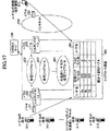
図34は、本発明の実施例3−1の認証連携型分散ファイアウォール装置の概略構成と、本発明の実施例3−1の認証連携型分散ファイアウォール装置が使用されるネットワークモデルを示すブロック図である。
[Example 3-1]
FIG. 34 is a block diagram illustrating a schematic configuration of the authentication collaboration type distributed firewall apparatus according to the embodiment 3-1 of the present invention and a network model in which the authentication collaboration type distributed firewall apparatus according to the embodiment 3-1 of the present invention is used. is there.
認証連携型分散ファイアウォール装置(以下、単に、ファイアウォール装置という。)501は、認証により接続を開始するユーザ(515−1)が使用するユーザ端末(502−1)と、ユーザ(515−2)が使用するユーザ端末(502−2)を収容し、外部ネットワーク(例えば、インターネット)503に接続されている。 An authentication cooperative distributed firewall apparatus (hereinafter simply referred to as a firewall apparatus) 501 includes a user terminal (502-1) used by a user (515-1) that starts a connection by authentication and a user (515-2). A user terminal (502-2) to be used is accommodated and connected to an external network (for example, the Internet) 503.
また、ファイアウォール装置501は、ユーザ固有のセキュリティポリシを保持するセキュリティポリシテーブル511を備えるセキュリティポリシサーバ504、およびファイアウォール装置501へ配布する識別子を保持する識別子管理テーブル512を備える識別子管理サーバ505と接続されている。
The
さらに、ファイアウォール装置501は、ユーザの認証情報513と、認証時にユーザ端末に付与するユーザ端末情報から成るプールテーブルを保持するユーザ端末情報部514を備える認証サーバ506とも接続されている。
Furthermore, the
ここで、前記認証サーバは、例えば、RAIDUS(Remote Authentication Dial-in User Service)サーバが使用可能であり、また、ユーザ端末情報部514に格納されるユーザ端末情報は、ユーザ端末に付与されるIPアドレスが使用可能である。
Here, for example, a RAIDUS (Remote Authentication Dial-in User Service) server can be used as the authentication server, and the user terminal information stored in the user
さらに、ユーザ端末(502−1,502−2)からネットワークヘの接続はPPP(Point to Point Protoco1)を使用し、認証にはPAP(Password Authentication Protocol)、または、CHAP(Challenge Handshake Authentication Protocol)が使用可能である。 Further, PPP (Point to Point Protocol 1) is used for connection from the user terminals (502-1, 502-2) to the network, and PAP (Password Authentication Protocol) or CHAP (Challenge Handshake Authentication Protocol) is used for authentication. It can be used.
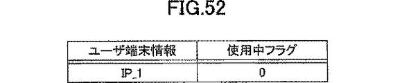
また、ファイアウォール装置501は、受信パケットに付属しているユーザ端末情報と、受信パケットをフィルタリングするフィルタリングテーブルを指し示す識別子とを結びつける振分け管理テーブル507と、実際のフィルタリングを行うファイアウォール部508を有している。
Further, the
さらに、ファイアウォール部508は、ユーザ(515−1)とユーザ(515−2)に共通するセキュリティポリシを保持する共通フィルタリングテーブル509と、ユーザ(515−1)、または、ユーザ(515−2)の個別セキュリティボリシを保持するための領域である個別フィルタリングテーブル領域を有する。
Further, the
この個別フィルタリングテーブル領域510は、識別情報を書き込む領域と、この識別情報を書き込む領域と結び付けられたセキュリティポリシを書込む領域に分かれている。
The individual
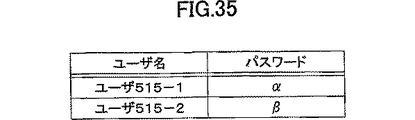
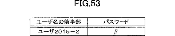
図35は、図34に示す認証サーバ内の認証情報513の詳細を示す図、図36は、図34に示す認証サーバ内のユーザ端末情報部514に保持されるプールテーブルの詳細を示す図である。
FIG. 35 is a diagram showing details of the
また、図37は、図34に示す識別子管理サーバ内の識別子管理テーブル512の詳細を示す図、図38は、図34に示すセキュリティポリシサーバ内のセキュリティポリシテーブル511の詳細を示す図、図39は、図34に示すファイアウォール装置内の初期状態の振分け管理テーブルの詳細を示す図である。 37 shows details of the identifier management table 512 in the identifier management server shown in FIG. 34. FIG. 38 shows details of the security policy table 511 in the security policy server shown in FIG. FIG. 35 is a diagram showing details of an initial distribution management table in the firewall apparatus shown in FIG. 34;
図40、図41は、図34のネットワークモデルの動作を示すシーケンスの一例を示す図であり、ユーザ(515−1)が外部ネットワーク503へ接続後、切断し、その後、ユーザ(515−2)が外部ネットワーク503へ接続後、切断を行うシーケンスを示したものである。
FIG. 40 and FIG. 41 are diagrams showing an example of a sequence showing the operation of the network model of FIG. 34. After the user (515-1) connects to the
始めに、ユーザ(515−1)の接続開始シーケンスについて説明する。 First, the connection start sequence of the user (515-1) will be described.
まず、ユーザ(515−1)はユーザ端末を介して、ファイアウォール装置501に、ユーザ名(ユーザ515−1)とパスワード(α)を送信する(図40の11−1,11−2)。
First, the user (515-1) transmits the user name (user 515-1) and the password (α) to the
このユーザ名(ユーザ515−1)とパスワード(α)を受信したファイアウォール装置501は、ユーザ名(ユーザ515−1)を保持(図40の11−3)するとともに、認証サーバ506ヘユーザ名(ユーザ515−1)とパスワード(α)を送信する(図40の11−4)。
The
認証サーバ506では、受信したユーザ名(ユーザ515−1)とパスワード(α)から認証情報513を検索し、認証可能と判定する(図40の11−5)。
The
また、ユーザ端末情報部514のプールテーブルから使用中フラグが「0」である使用可能なユーザ端末情報(IP_1)を抽出し、抽出した使用可能フラグを「1」にし、認証了承通知とともに、抽出したユーザ端末情報(IP_1)をファイアウォール装置501通知する(図40の11−6,11−7)。
Also, usable user terminal information (IP_1) whose in-use flag is “0” is extracted from the pool table of the user
ファイアウォール装置501は、受信したユーザ端末情報(IP_1)を保持し、このユーザ端末情報とユーザ端末が接続する回線を結びつける(図40の11−8)とともに、前記保持したユーザ名(ユーザ515−1)を識別子管理サーバ505に送信する(図40の11−9)。
The
識別子管理サーバ505は、受信したユーザ名(ユーザ515−1)を元に識別子管理テーブル512を検索し、ユーザ名に結びつられた共通フィルタリングテーブルID(共通509)と個別フィルタリングテーブルID(個別510−1)を抽出し、ファイアウォール装置501へこの識別子(共通509,個別510−1)を送信する(図40の11−10、11−11)。
The
ファイアウォール装置501は、受信した個別フィルタリングテーブルID(個別510−1)を保持するとともに、受信した共通フィルタリングテーブルID(共通509)と、個別フィルタリングテーブルID(個別510−1)と、保持しているユーザ端末情報(IP_1)とを、図39に示す振分け管理テーブル507に書き込む(図40の11−12)。
The
また、保持しているユーザ名(ユーザ515−1)をセキュリティポリシサーバ504へ送信する(図40の11−13)。 The held user name (user 515-1) is transmitted to the security policy server 504 (11-13 in FIG. 40).
セキュリティポリシサーバ504は、受信したユーザ名(ユーザ515−1)を元に、保持するセキュリティポリシテーブル512を検索し、ユーザ名と結び付けられた個別セキュリティポリシ(ルール1−1〜ルール1−m)を抽出し(図40の11−14)、ファイアウォール装置501へ送信する(図40の11−15)。
The
ファイアウォール装置501は、保持している個別フィルタリングテーブルID(個別510−1)を個別フィルタリングテーブル領域510の識別情報に書込むとともに、受信した個別セキュリティポリシ(ルール1−1〜ルール1−m)をセキュリティポリシ領域へ書き込む(図40の11−16)。
The
この一連の処理を実施後、保持しているユーザ端末情報(IP_1)を含む認証成功通知をユーザ端末(502−1)へ通知する(図40の11−17)。 After performing this series of processing, a notification of successful authentication including the held user terminal information (IP_1) is sent to the user terminal (502-1) (11-17 in FIG. 40).
以上で接続開始シーケンスが終了し、これにより、ユーザ(515−1)は、ユーザ端末(502−1)を介して外部ネットワーク503と接続可能になる。
The connection start sequence is thus completed, and the user (515-1) can connect to the
次に、ユーザ端末(502−1)と外部ネットワーク503との通信シーケンスについて説明する。
Next, a communication sequence between the user terminal (502-1) and the
ユーザ端末(502−1)から外部ネットワーク503ヘパケットを転送する場合、ユーザ端末(502−1)は接続開始シーケンスの最後に受けたユーザ端末情報(IP_1)を自身のアドレスとし、当該アドレスをパケットに付与してファイアウォール装置501へ転送する(図40の11−18)。
When transferring a packet from the user terminal (502-1) to the
ファイアウォール装置501は、受信したパケットからユーザ端末情報(IP_1)を抽出し、このユーザ端末情報(IP_1)をキーにして、振分け管理テーブル507を検索し、共通フィルタリングテーブルID(共通509)と個別フィルタリングテーブルID(個別510−1)を抽出する(図40の11−19)。
The
次に、ファイアウォール部508において、抽出した共通フィルタリングテーブルID(共通509)と、個別フィルタリングテーブルID(個別510−1)で示されるフィルタリングテーブルを用い、パケットをフィルタリング(図40の11−20、11−21)した後、外部ネットワーク503へ転送する(図40の11−22)。
Next, the
また、外部ネットワーク503からユーザ端末(502−1)に対するパケットを受信し(図40の11−23)、ユーザ端末(502−1)に転送する場合、外部ネットワーク503からのパケットには、宛先アドレスとしてユーザ端末情報(IP_1)が付与されているので、ファイアウォール装置501は、受信したパケットから、このユーザ端末情報(IP_1)を抽出し(図40の11−24)、前述したユーザ端末(502−1)から外部ネットワーク503へ転送するパケットと同様のシーケンスにより、パケットをフィルタリング(図40の11−25、11−26)した後、ユーザ端末(502−1)ヘパケットを転送する(図40の11−27)。
When a packet for the user terminal (502-1) is received from the external network 503 (11-23 in FIG. 40) and transferred to the user terminal (502-1), the packet from the
本実施例のファイアウォール装置501は、以上の処理により、ユーザ端末側および外部ネットワーク側の両方向から送信されるパケットに対するフィルタリング処理を行い、パケットを転送する。
The
次に、ユーザ(515−1)からの切断シーケンスについて説明する。 Next, a disconnection sequence from the user (515-1) will be described.
切断時には、ユーザ(515−1)からユーザ端末(502−1)を介して、切断要求がファイアウォール装置501へ通知される(図40の11−28、11−29)。
At the time of disconnection, a disconnection request is notified from the user (515-1) to the
ファイアウォール装置501は、切断要求を受信すると、受信した回線を調べ、接続開始シーケンス時に、結びつけたユーザ端末情報(IP_1)を導き出す。
When the
このユーザ端末情報を元に、振分け管理テーブル507のユーザ端末情報(IP_1)と関連するエントリから個別フィルタリングテーブルID(個別510−1)を抽出後、このエントリを削除する(図40の11−30)。 Based on this user terminal information, the individual filtering table ID (individual 510-1) is extracted from the entry associated with the user terminal information (IP_1) in the distribution management table 507, and then this entry is deleted (11-30 in FIG. 40). ).
ファイアウォール部508の個別フィルタリングテーブル領域510の中で、抽出した個別フィルタリングテーブルID(個別510−1)が記された識別情報とそれに関連するセキュリティポリシ領域を削除する(図40の11−31)。
In the individual
また、導き出したユーザ端末情報(IP_1)を認証サーバ506に送信し(図40の11−32)、認証サーバ506は、受信したユーザ端末情報が関連するユーザ端末情報部514のプールテーブルのエントリの使用中フラグを「0」に戻す(図40の11−33)。
Further, the derived user terminal information (IP_1) is transmitted to the authentication server 506 (11-32 in FIG. 40), and the
このように、接続シーケンスで変更した各種テーブル内容を接続前の状態に戻し、切断シーケンスが終了する。 In this way, the contents of the various tables changed in the connection sequence are returned to the state before connection, and the disconnection sequence ends.
続いて、ユーザ(515−2)の接続開始シーケンス、通信シーケンス、切断シーケンスともユーザ(515−1)と同様の手段をとり、実施される(図41の11−34〜11−66)。 Subsequently, the connection start sequence, the communication sequence, and the disconnection sequence of the user (515-2) are implemented by taking the same means as the user (515-1) (11-34 to 11-66 in FIG. 41).
ユーザ(515−2)のシーケンスの特徴としては、ユーザ(515−1)の切断シーケンスにより、ユーザ(515−1)に関する情報は、ファイアウォール装置501の振分け管理テーブル507、個別フィルタリングテーブル領域510にないため、同じ領域にユーザ(515−2)に関する情報を書込むことができ、また、ユーザ端末(515−1)が使用したユーザ端末情報(IP_1)も使用可能であり、ユーザ端末情報が、ユーザ(515−1)と同じユーザ端末情報(IP_1)であっても、ユーザ(515−2)用のセキュリティポリシでフィルタリングすることができる点である。
As a feature of the sequence of the user (515-2), there is no information about the user (515-1) in the distribution management table 507 and the individual
これにより、本発明が解決しようとする課題の内、個別フィルタリングテーブル領域510、共通フィルタリングテーブル509を用い、個別フィルタリングテーブル領域510に書込むセキュリティポリシのみロードすることで、ロード負荷を軽減することが可能となる。
As a result, among the problems to be solved by the present invention, by using only the individual
また、ユーザ端末が接続中のみ、個別フィルタリングテーブル領域510と振分け管理テーブル507の領域を使用し、切断中は、この領域を使用しないことで、ファイアウォール装置501の個別フィルタリングテーブル領域510と振分け管理テーブル507の内容を、同時に接続するユーザ端末数分だけ保持すれば良いので、保持するセキュリティポリシの容量を少なくすることが可能となる。
Also, the individual
また、接続毎に付与されるユーザ端末情報とセキュリティポリシを関連付けることで、過去の別ユーザ端末のユーザ端末情報と重複しても、使用ユーザに対応したフィルタリングを実施することが可能となる。 Further, by associating the user terminal information given for each connection with the security policy, it becomes possible to perform filtering corresponding to the user who uses the user terminal information even if it overlaps with the user terminal information of another user terminal in the past.
[実施例3−2]
図42は、本発明の実施例3−2のファイアウォール装置の概略構成と、本発明の実施例3−2のファイアウォール装置が使用されるネットワークモデルを示すブロック図である。
[Example 3-2]
FIG. 42 is a block diagram illustrating a schematic configuration of the firewall apparatus according to the embodiment 3-2 of the present invention and a network model in which the firewall apparatus according to the embodiment 3-2 of the present invention is used.
図42に示すネットワークモデルでは、図34に示すネットワークモデルに、ファイアウォール装置1201と、このファイアウォール装置1201に接続するユーザ端末1202が新たに追加される。
In the network model shown in FIG. 42, a
また、このファイアウォール装置1201に、ユーザ(515−1)が接続可能であり、さらに、ファイアウォール装置1201は、外部ネットワーク503と、セキュリティポリシサーバ504と、識別子管理サーバ505と、認証サーバ506とに接続される。
In addition, a user (515-1) can connect to the
ファイアウォール装置1201は、受信パケットに付属しているユーザ端末情報と受信パケットをフィルタリングするテーブルを指し示す識別子を結びつける情報を保持する振分け管理テーブル1207を有し、実際のフィルタリングを行うファイアウォール部1208を有している。
The
さらに、ファイアウォール部1208は、ユーザ(515−1)を含めた複数のユーザに共通するセキュリティポリシを保持する共通フィルタリングテーブル1209と、ユーザ(515−1)の個別セキュリティポリシを保持するための領域である個別フィルタリングテーブル領域1210を有している。
Further, the
この個別フィルタリングテーブル領域1210は、識別情報を書き込む領域とセキュリティポリシを書込む領域に分かれている。
The individual
図43は、図42のネットワークモデルの動作を示すシーケンスの一例を示す図であり、図40で示すシーケンスの後、ユーザ(515−1)が、ファイアウォール装置1201に接続するユーザ端末1202から再度外部ネットワーク503へ接続し、通信を行い、切断するシーケンスを示したものである。
FIG. 43 is a diagram showing an example of a sequence showing the operation of the network model of FIG. 42. After the sequence shown in FIG. 40, the user (515-1) re-externals from the
図43の12−1〜12−33に示す、ユーザ(515−1)が、ユーザ端末1202へ移動し、再接続を行う接続シーケンス、通信を行うシーケンス、および切断をシーケンスは、図40に示すファイアウォール装置501で行うシーケンスと同様であるので、再度の説明は省略する。
The connection sequence in which the user (515-1) shown to 12-1 to 12-33 in FIG. 43 moves to the
また、ファイアウォール装置1201に、セキュリティポリシサーバ504から送信される、ユーザ(515−1)用の個別セキュリティポリシも、識別子管理サーバ505から送信される各種識別子も、図40において、ファイアウォール装置501に送信される情報と同じである。
Also, the individual security policy for the user (515-1) transmitted from the
これにより、本実施例では、ユーザが、収容されるファイアウォール装置を変更しても、このユーザに対応したセキュリティポリシを適用することが可能となる。 Thereby, in this embodiment, even if the user changes the firewall apparatus accommodated, the security policy corresponding to this user can be applied.
[実施例3−3]
図44は、本発明の実施例3−3のファイアウォール装置の概略構成と、本発明の実施例3−3のファイアウォール装置が使用されるネットワークモデルを示すブロック図である。
[Example 3-3]
FIG. 44 is a block diagram showing a schematic configuration of a firewall apparatus according to Embodiment 3-3 of the present invention and a network model in which the firewall apparatus according to Embodiment 3-3 of the present invention is used.
本実施例は、識別子管理サーバ505に保持される、ユーザ名と各種識別子を対応付ける識別子管理テーブル512を、ファイアウォール装置501の内部に保持する点で、前述の実施例3−1と相異する。
This embodiment is different from the above-described Embodiment 3-1 in that an identifier management table 512 that is associated with a user name and various identifiers and is held in the
図45は、図44のネットワークモデルの動作を示すシーケンスの一例を示す図であり、識別子管理サーバ505との通信部分が削除され、新たに、ファイアウォール装置501の内部に保持される識別子管理テーブル512とのシーケンスが付加されている点で、図40に示すシーケンスと相異する。
FIG. 45 is a diagram showing an example of a sequence showing the operation of the network model of FIG. 44, in which the communication part with the
図40のシーケンスからの変更部分のシーケンスは、図45の11−8において、認証サーバ506から受信したユーザ情報を保持し、ユーザ端末(502−1)の接続回線とこのユーザ情報を結びつけた後、図45の11−3で保持したユーザ名を検索キーとし、識別子管理テーブル512を検索し、共通フィルタリングテーブルID、個別フィルタリングテーブルIDを抽出(図45の15−9,15−10,15−11)する点である。
The sequence of the changed part from the sequence of FIG. 40 is obtained by holding the user information received from the
本実施例では、ファイアウォール装置501が、収容する可能性のある全ユーザの各種識別子を含む識別子管理テーブル512を保持しなければ成らなくなるため、ファイアウォール装置501のメモリ容量が余分に必要になるか、または、収容可能なユーザ数が減少するが、識別子管理サーバと通信を行うこと無く、動作が可能となる。
In this embodiment, since the
[実施例3−4]
図46は、本発明の実施例3−4のファイアウォール装置の概略構成と、本発明の実施例3−4のファイアウォール装置が使用されるネットワークモデルを示すブロック図である。
[Example 3-4]
FIG. 46 is a block diagram illustrating a schematic configuration of a firewall apparatus according to Embodiment 3-4 of the present invention and a network model in which the firewall apparatus according to Embodiment 3-4 of the present invention is used.
本実施例は、セキュリティポリシサーバ504に保持される、ユーザ名と個別セキュリティポリシを対応付けるセキュリティポリシテーブル511を、ファイアウォール装置501の内部に保持する点で、前述の実施例3−1と相異する。
This embodiment is different from the above-described embodiment 3-1 in that a security policy table 511 that is held in the
図47は、図46のネットワークモデルの動作を示すシーケンスの一例を示す図であり、セキュリティポリシサーバ504との通信部分が削除され、新たに、ファイアウォール装置501の内部に保持されるセキュリティポリシテーブル511とのシーケンスが付加されている点で、図40に示すシーケンスと相異する。
FIG. 47 is a diagram showing an example of a sequence showing the operation of the network model of FIG. 46, in which the communication part with the
図40のシーケンスからの変更部分のシーケンスは、図47の11−12で振分け管理テーブル507に各種識別子を書き込んだ後に、図47の11−3で保持したユーザ名を検索キーとし、セキュリティポリシテーブル511を検索し、ユーザ名に対応したセキュリティポリシを抽出(図47の17−13,17−14,17−15)する点である。 The sequence of the changed part from the sequence of FIG. 40 is a security policy table in which various identifiers are written in the distribution management table 507 in 11-12 of FIG. 47 and the user name held in 11-3 of FIG. 511 is searched, and the security policy corresponding to the user name is extracted (17-13, 17-14, 17-15 in FIG. 47).
本実施例では、ファイアウォール装置501が、収容する可能性のある全ユーザの個別セキュリティポリシを含むセキュリティポリシテーブル511を保持しなければ成らなくなるため、ファイアウォール装置501のメモリ容量が余分に必要になるか、または、収容可能なユーザ数が減少するが、セキュリティポリシサーバと通信を行うこと無く、動作が可能となる。
In this embodiment, since the
[実施例3−5]
図48は、本発明の実施例3−5のファイアウォール装置の概略構成と、本発明の実施例3−5のファイアウォール装置が使用されるネットワークモデルを示すブロック図である。
[Example 3-5]
FIG. 48 is a block diagram illustrating a schematic configuration of a firewall apparatus according to Embodiment 3-5 of the present invention and a network model in which the firewall apparatus according to Embodiment 3-5 of the present invention is used.
本実施例は、セキュリティポリシサーバ504に保持される、ユーザ名と個別セキュリティポリシを対応付けるセキュリティポリシテーブル511と、識別子管理サーバ505に保持される、ユーザ名と各種識別子を対応付ける識別子管理テーブル512とを、ファイアウォール装置501の内部に保持する点で、前述の実施例3−1と相異する。
In this embodiment, a security policy table 511 that associates a user name with an individual security policy, which is held in the
図49は、図48のネットワークモデルの動作を示すシーケンスの一例を示す図であり、セキュリティポリシサーバ504との通信部分と識別子管理サーバ505との通信部分が削除され、新たに、ファイアウォール装置501の内部に保持されるセキュリティポリシテーブル511と、識別子管理テーブル512のシーケンスが付加された点で、図40に示すシーケンスと相異する。
FIG. 49 is a diagram showing an example of a sequence showing the operation of the network model of FIG. 48. The communication part with the
図40のシーケンスからの変更部分のシーケンスは、図49の11−8において、認証サーバ506から受信したユーザ情報を保持し、ユーザ端末(502−1)の接続回線とこのユーザ情報を結びつけた後、図49の11−3で保持したユーザ名を検索キーとし、識別子管理テーブル512を検索し、共通フィルタリングテーブルID、個別フィルタリングテーブルIDを抽出(図49の19−9,19−10,19−11)する点と、図49の11−12で振分け管理テーブル507に各種識別子を書き込んだ後に、図49の11−3で保持したユーザ名を検索キーとし、セキュリティポリシテーブル511を検索し、ユーザ名に対応したセキュリティポリシを抽出(図49の19−13,19−14,19−15)する点である。
The sequence of the changed part from the sequence of FIG. 40 is obtained by holding the user information received from the
本実施例では、ファイアウォール装置501が、収容する可能性のある全ユーザの個別セキュリティポリシを含むセキュリティポリシテーブル511を保持しなければ成らなくなるため、ファイアウォール装置501のメモリ容量が余分に必要になるか、または、収容可能なユーザ数が減少し、および、収容する可能性のある全ユーザの各種識別子を含む識別子管理テーブル512を保持しなければ成らなくなるため、ファイアウォール装置501のメモリ容量がさらに余分に必要になるか、または、収容可能なユーザ数がさらに減少するが、セキュリティポリシサーバ、識別子管理サーバと通信を行うこと無く、動作が可能となる。
In this embodiment, since the
[実施例3−6]
図50は、本発明の実施例3−6のファイアウォール装置の概略構成と、本発明の実施例3−6のファイアウォール装置が使用されるネットワークモデルを示すブロック図である。
[Example 3-6]
FIG. 50 is a block diagram illustrating a schematic configuration of a firewall apparatus according to Embodiment 3-6 of the present invention and a network model in which the firewall apparatus according to Embodiment 3-6 of the present invention is used.
ファイアウォール装置2001は、契約ネットワーク1(例えば、ISP;Internet Service Provider)(2016−1)を介して外部ネットワーク2003に接続し、認証によりこの接続を開始するユーザ(2015−1)が使用するユーザ端末(2002−1)と、契約ネットワーク2(2016−2)を介して外部ネットワーク2003に接続し、認証によりこの接続を開始するユーザ(2015−2)が使用するユーザ端末(2002−2)を収容する。
The
また、ファイアウォール装置2001は、ユーザ固有のセキュリティポリシを保持するセキュリティポリシテーブル2011を有するセキュリティポリシサーバ2004、および、ファイアウォール装置2001へ配布する識別子を保持する識別子管理テーブル2012を有する識別子管理サーバ2005とも接続されている。
The
さらに、ファイアウォール装置2001は、ユーザの認証情報(2013−1)と、認証時にユーザ端末に付与するユーザ端末情報から成るプールテーブルを保持しているユーザ端末情報部(2014−1)を有し、契約ネットワーク1を介して外部ネットワークに接続するユーザを認証する認証サーバ1(2006−1)とも接続されている。
Further, the
さらに、ファイアウォール装置2001は、ユーザの認証情報(2013−2)と、認証時にユーザ端末に付与するユーザ端末情報から成るプールテーブルを保持しているユーザ端末情報部(2014−2)を有し、契約ネットワーク2を介して外部ネットワークに接続するユーザを認証する認証サーバ2(2006−2)とも接続されている。
Further, the
また、ファイアウォール装置2001は、受信パケットに付属しているユーザ端末情報と受信パケットをフィルタリングする仮想ファイアウォール(2014−1,2014−2)と、フィルタリングテーブルを指し示す識別子を結びつける振分け管理テーブル2007を有している。
Further, the
さらに、ファイアウォール装置2001は、実際のフィルタリングを行うファイアウォール部2008を有し、このファイアウォール部2008は、契約ネットワーク1(2016−1)を介して外部ネットワーク2003と接続するユーザ端末に関係するパケットのフィルタリングを行う仮想ファイアウォール1(2014−1)と、契約ネットワーク2(2016−2)を介して外部ネットワーク2003と接続するユーザ端末に関係するパケットのフィルタリングを行う仮想ファイアウォール2(2014−2)を有している。
Further, the
仮想ファイアウォール1(2014−1)は、仮想ファイアウォール1(2014−1)により、フィルタリングを行う複数のユーザに共通するセキュリティポリシが保持される共通フィルタリングテーブル(2009−1)と、個別ユーザ毎のセキュリティポリシを保持する領域である個別フィルタリングテーブル領域(2010−1)を有している。 The virtual firewall 1 (2014-1) includes a common filtering table (2009-1) in which security policies common to a plurality of users who perform filtering by the virtual firewall 1 (2014-1), and security for each individual user. It has an individual filtering table area (2010-1) which is an area for holding a policy.
また、個別フィルタリングテーブル領域(2010−1)は、識別情報を書き込む領域と、この識別情報を書き込む領域と結び付けられたセキュリティポリシを書き込む領域に分かれている。 The individual filtering table area (2010-1) is divided into an area for writing identification information and an area for writing a security policy associated with the area for writing the identification information.
仮想ファイアウォール1(2014−1)と同様に、仮想ファイアウォール2(2014−2)も、共通フィルタリングテーブル(2009−2)と、個別フィルタリングテーブル領域(2010−2)とを有し、個別フィルタリングテーブル領域(2010−2)は、識別情報を書き込む領域と、この識別情報を書き込む領域と結び付けられたセキュリティポリシを書き込む領域に分かれている。 Similar to the virtual firewall 1 (2014-1), the virtual firewall 2 (2014-2) also has a common filtering table (2009-2) and an individual filtering table area (2010-2). (2010-2) is divided into an area for writing identification information and an area for writing a security policy associated with the area for writing the identification information.
図51は、図50に示す認証サーバ1内の認証情報(2013−1)の詳細を示す図であり、図52は、図50に示す認証サーバ1内のユーザ端末情報部(2014−1)に保持されるプールテーブルの詳細を示す図である。
51 is a diagram showing details of the authentication information (2013-1) in the
同様に、図53は、図50に示す認証サーバ2内の認証情報(2013−2)の詳細を示す図であり、図54は、図50に示す認証サーバ2内のユーザ端末情報部(2014−2)に保持されるプールテーブルの詳細を示す図である。
Similarly, FIG. 53 is a diagram showing details of the authentication information (2013-2) in the
図55は、ユーザ(2015−1)が、ユーザ端末(2002−1)を介してファイアウォール装置2001に送信するユーザ名を示す図であり、図56は、ユーザ(2015−2)が、ユーザ端末(2002−2)を介してファイアウォール装置2001に送信するユーザ名を示す図である。
FIG. 55 is a diagram illustrating a user name that the user (2015-1) transmits to the
図57は、図50に示す識別子管理サーバ内の識別子管理テーブル2012の詳細を示す図であり、図58は、図50に示すセキュリティポリシサーバ内のセキュリティポリシテーブル2011の詳細を示す図である。 57 is a diagram showing details of the identifier management table 2012 in the identifier management server shown in FIG. 50, and FIG. 58 is a diagram showing details of the security policy table 2011 in the security policy server shown in FIG.
図59、図60は、図50のネットワークモデルの動作を示すシーケンスの一例を示す図であり、ユーザ(2015−1)が、契約ネットワーク1(2016−1)を介して、外部ネットワーク2003へ接続後、切断するシーケンスと、ユーザ(2015−2)が、契約ネットワーク2(2016−2)を介して外部ネットワーク2003へ接続後、切断するシーケンスを示すものである。
59 and 60 are diagrams showing an example of a sequence showing the operation of the network model of FIG. 50, in which the user (2015-1) connects to the
始めに、ユーザ(2015−1)の接続開始シーケンスについて説明する。 First, the connection start sequence of the user (2015-1) will be described.
まず、ユーザ(2015−1)は、ユーザ端末(2002−1)を介して、ファイアウォール装置2001に、ユーザ名(ユーザ2015−1_2016−1)とパスワード(α)を送信する(図59の21−1,21−2)。
First, the user (2015-1) transmits the user name (user 2015-1_2016-1) and the password (α) to the
このユーザ名(ユーザ2015−1_2016−1)とパスワード(α)を受信したファイアウォール装置2001は、ユーザ名の前半部(ユーザ2015−1)を保持(図59の21−3)するとともに、ユーザ名の後半部(2016−1)から、認証サーバ1(2006−1)へ認証情報を送信することを決定し、ユーザ名の前半部(ユーザ2015−1)とパスワード(α)を送信する(図59の21−4)。
The
認証サーバ1(2003−1)では、受信したユーザの前半部(ユーザ2015−1)とパスワード(α)から認証情報(2013−1)を検索し、認証可能と判定する(図59の21−5)。 The authentication server 1 (2003-1) searches the authentication information (2013-1) from the received first half of the user (user 2015-1) and the password (α) and determines that authentication is possible (21- in FIG. 59). 5).
また、ユーザ端末情報部(2014−1)のプールテーブルから使用中フラグが「0」である使用可能なユーザ端末情報(IP_1)を抽出し(図59の21−6)、抽出した使用可能フラグを「1」にし、認証了承通知とともに、このユーザ端末情報(IP_1)をファイアウォール装置2001へ通知する(図59の21−7)。
Further, usable user terminal information (IP_1) whose in-use flag is “0” is extracted from the pool table of the user terminal information section (2014-1) (21-6 in FIG. 59), and the extracted usable flag is extracted. Is set to “1”, and the user terminal information (IP_1) is notified to the
ファイアウォール装置2001は、受信したユーザ端末情報(IP_1)を保持し(図59の21−8)、このユーザ端末情報(IP_1)と、ユーザ端末(2002−1)が接続する回線を結びつけるとともに、保持したユーザ名の前半部(ユーザ2015−1)を識別子管理サーバ2005に送信する(図59の21−9)。
The
識別子管理サーバ2005は、受信したユーザ名の前半部(ユーザ2015−1)を元に識別子管理テーブル2012を検索し、ユーザ名の前半部(ユーザ2015−1)に結びつられた仮想ファイアウォールID(仮想2014−1)と、共通フィルタリングテーブルID(共通2009−1)と、個別フィルタリングテーブルID(個別2010−1)を抽出し(図59の21−10)、ファイアウォール装置2001へこの識別子を送信する(図59の21−11)。
The
ファイアウォール装置2001は、受信した個別フィルタリングテーブルID(個別2010−1)を保持すると伴に、受信した仮想ファイアウォールID(仮想2014−1)と、共通フィルタリングテーブルID(共通2009−1)と、個別フィルタリングテーブルID(個別2010−1)と、保持しているユーザ端末情報(IP_1)を、振分け管理テーブル2007に書き込む(図59の21−12)。
The
また、保持しているユーザ名の前半部(ユーザ2015−1)をセキュリティポリシサーバ2004へ送信する(図59の21−13)。 Also, the first half of the stored user name (user 2015-1) is transmitted to the security policy server 2004 (21-13 in FIG. 59).
セキュリティポリシサーバ2004は、受信したユーザ名の前半部(ユーザ2015−1)を元に、保持するセキュリティポリシテーブル2011を検索し、ユーザ名の前半部(ユーザ2015−1)と結び付けられた個別セキュリティポリシ(ルール1−1〜ルール1−m)を抽出し(図59の21−14)、ファイアウォール装置2001へ送信する(図59の21−15)。
The
ファイアウォール装置2001は、保持している個別フィルタリングテーブルID(個別2010−1)を個別フィルタリングテーブル領域(2010−1)の識別情報領域に書込むとともに、受信した個別セキュリティポリシをセキュリティポリシ領域へ書き込む(図59の21−16)。
The
この一連の処理を実施後、保持しているユーザ端末情報(IP_1)を含む認証成功通知をユーザ端末(2002−1)へ通知する(図59の21−17)。 After performing this series of processing, a notification of successful authentication including the held user terminal information (IP_1) is sent to the user terminal (2002-1) (21-17 in FIG. 59).
以上で接続開始シーケンスが終了し、これにより、ユーザ(2015−1)は、ユーザ端末(2002−1)を介して外部ネットワーク2003と接続可能になる。
Thus, the connection start sequence is completed, and thus the user (2015-1) can connect to the
次に、ユーザ端末(2002−1)と外部ネットワーク2003との通信シーケンスについて説明する。
Next, a communication sequence between the user terminal (2002-1) and the
ユーザ端末(2002−1)から外部ネットワーク2003ヘパケットを転送する場合、ユーザ端末(2002−1)は接続開始シーケンスの最後に受けたユーザ端末情報(IP_1)を自身のアドレスとして、パケットに付与してファイアウォール装置2001へ転送する(図59の21−18)。
When transferring a packet from the user terminal (2002-1) to the
ファイアウォール装置2001は、受信したパケットからユーザ端末情報(IP_1)を抽出し、このユーザ端末情報(IP_1)をキーに、振分け管理テーブル2007を検索し、仮想ファイアウォールID(仮想2014−1)と、共通フィルタリングテーブルID(共通2009−1)と、個別フィルタリングテーブルID(個別2010−1)を抽出する(図59の21−19)。
The
次に、受信したパケットを、抽出した仮想ファイアウォールID(仮想2014−1)で示される仮想ファイアウォール1(2014−1)ヘ振分けるとともに、抽出した仮想ファイアウォール(仮想2014−1)で示される仮想ファイァウォールのフィルタリングテーブルの内、抽出した共通フィルタリングテーブルID(共通2009−1)と、個別フィルタリングテーブルID(個別2010−1)で示されるフィルタリングテーブルを用いパケットをフィルタリング(図59の21−20,21−21)した後、契約ネットワーク1(2016−1)を介して、外部ネットワーク2003へ転送する(図59の21−22)。
Next, the received packet is distributed to the virtual firewall 1 (2014-1) indicated by the extracted virtual firewall ID (virtual 2014-1), and the virtual file indicated by the extracted virtual firewall (virtual 2014-1) is assigned. Filtering packets using the filtering table indicated by the extracted common filtering table ID (common 2009-1) and the individual filtering table ID (individual 2010-1) in the firewall filtering table (21-20, FIG. 59). 21-21), the data is transferred to the
また、外部ネットワーク2003から契約ネットワーク1(2016−1)を介して、ユーザ端末(2002−1)宛のパケットを受信し(図59の21−23)、ユーザ端末(2002−1)ヘ転送する場合、外部ネットワーク2003からのパケットには、宛先アドレスとしてユーザ端末情報(IP_1)が付与されており、ファイアウォール装置2001は、受信したパケットからこのユーザ端末情報(IP_1)を抽出し(図59の21−24)、前述したユーザ端末(2002−1)から外部ネットワーク2003へのパケットと同様のシーケンスにより、パケットをフィルタリング(図59の21−25,21−26)した後、ユーザ端末(2002−1)ヘパケットを転送する(図59の21−27)。
Also, a packet addressed to the user terminal (2002-1) is received from the
本実施例のファイアウォール装置2001は、以上の処理により、ユーザ端末側および外部ネットワーク側の両方向から送信されるパケットに対するフィルタリング処理を行い、パケットを転送する。
The
次に、ユーザ(2015−1)からの切断シーケンスについて説明する。 Next, a disconnection sequence from the user (2015-1) will be described.
切断時には、ユーザ(2015−1)からユーザ端末(2002−1)を介して、切断要求がファイアウォール装置2001へ通知される(図59の21−28,21−29)。
At the time of disconnection, a disconnection request is notified from the user (2015-1) to the
ファイアウォール装置2001は、切断要求を受信すると、受信した回線を調べ、接続開始シーケンス時に、結びつけたユーザ端末情報(IP_1)を導き出す。
When the
このユーザ端末情報(IP_1)を元に、振分け管理テーブル2007のユーザ端末情報(IP_1)と関連するエントリから仮想ファイアウォールID(仮想2014−1)と個別フィルタリングテーブルID(個別2010−1)を抽出後、このエントリを削除する(図59の21−30)。 After extracting the virtual firewall ID (virtual 2014-1) and the individual filtering table ID (individual 2010-1) from the entry related to the user terminal information (IP_1) in the distribution management table 2007 based on this user terminal information (IP_1) This entry is deleted (21-30 in FIG. 59).
次に、抽出した仮想ファイアウォールID(仮想2014−1)で示される仮想ファイアウォール1(2014−1)の個別フィルタリングテーブル領域(2010−1)の中で、抽出した個別フィルタリングテーブルID(個別2010−1)が記された識別情報とそれに関連するセキュリティポリシ領域を削除する(図59の21−31)。 Next, in the individual filtering table area (2010-1) of the virtual firewall 1 (2014-1) indicated by the extracted virtual firewall ID (virtual 2014-1), the individual filtering table ID (individual 2010-1) extracted. ) And the security policy area associated therewith are deleted (21-31 in FIG. 59).
また、切断要求を受信して導き出したユーザ端末情報(IP_1)を認証サーバ1(2006−1)に送信する(図59の21−32)。 Also, the user terminal information (IP_1) derived by receiving the disconnection request is transmitted to the authentication server 1 (2006-1) (21-32 in FIG. 59).
認証サーバ1(2006−1)は、受信したユーザ端末情報(IP_1)が関連するユーザ端末情報部(2014−1)のプールテーブルのエントリの使用中フラグを「0」に戻す(図59の21−33)。 The authentication server 1 (2006-1) returns the in-use flag of the entry in the pool table of the user terminal information section (2014-1) associated with the received user terminal information (IP_1) to “0” (21 in FIG. 59). -33).
このように、接続シーケンスで変更した各種テーブル内容を接続前の状態に戻し、切断シーケンスが終了する。 In this way, the contents of the various tables changed in the connection sequence are returned to the state before connection, and the disconnection sequence ends.
また、ユーザ(2015−2)の接続開始シーケンス、通信シーケンス、切断シーケンスも、ユーザ(2015−1)と同様の手段をとり、実施される(図60の21−34〜21−66)。 Further, the connection start sequence, the communication sequence, and the disconnection sequence of the user (2015-2) are performed by using the same means as the user (2015-1) (21-34 to 21-66 in FIG. 60).
このように、本実施例では、ファイアウォール装置2001を複数のファイアウォールとして動作させ、ファイアウォール毎に、個別認証サーバ(2006−1,2006−2)でユーザを認証し、ファイアウォール毎に、契約ネットワーク(2016−1,2016−2)を介して外部ネットワーク2003に接続でき、且つ、ユーザ毎にセキュリティポリシをロードすることが可能となる。
As described above, in this embodiment, the
なお、前述の説明では、セキュリティポリシサーバ(504,2004)、および、識別子管理サーバ(505,2005)が一台の場合について説明したが、本実施例の各ファイアウォール装置を、同じセキュリティポリシテーブルを有する2台のセキュリティポリシサーバ、あるいは、同じ識別子管理テーブルを有する2台のセキュリティポリシサーバと接続可能としてもよい。 In the above description, the case where there is one security policy server (504, 2004) and identifier management server (505, 2005) has been described. However, each firewall apparatus of the present embodiment has the same security policy table. It may be connectable to two security policy servers having two or two security policy servers having the same identifier management table.
(実施例3−1〜3−6の効果)
実施例3−1〜3−6のファイアウォール装置によれば、収容するネットワークまたは端末が、動的に接続、切断を行い、あるいは、収容されるファイアウォール装置を変更する場合に、保持するセキュリティポリシ容量を最適に保つことが可能になり、ファイアウォール装置にロードするセキュリティポリシ量を軽減することが可能となる。
(Effects of Examples 3-1 to 3-6)
According to the firewall apparatus of Examples 3-1 to 3-6, when the accommodated network or terminal dynamically connects / disconnects or changes the accommodated firewall apparatus, the security policy capacity to be retained Can be kept optimal, and the amount of security policy loaded on the firewall device can be reduced.
なお、これまでに説明した各実施例におけるファイアウォール装置は、例えば、通信装置を備えたコンピュータシステムに、各実施例において説明した処理を実行するプログラムを搭載することにより実現できる。当該コンピュータシステムは、例えば、図61に示すように、CPU600、メモリ602、ハードディスク601、入出力装置603、通信装置604を備えている。各実施例の処理において保持されるデータは、例えばメモリ602に保持される。また、他のサーバとの通信手段として通信装置604が用いられる。なお、ルータなども上記のコンピュータシステムに含まれるものである。
The firewall device in each embodiment described so far can be realized, for example, by mounting a program for executing the processing described in each embodiment in a computer system provided with a communication device. For example, as shown in FIG. 61, the computer system includes a
なお、本発明は、上記の実施例に限定されることなく、特許請求の範囲内で種々変更・応用が可能である。 The present invention is not limited to the above-described embodiments, and various modifications and applications can be made within the scope of the claims.
Claims (42)
ユーザ名と仮想ファイアウォールIDを管理する振分け管理テーブルと、
ユーザ端末からのネットワーク接続のための認証情報を受信すると、それに記載されているユーザ名を保持する手段と、
認証情報を認証サーバに通知する手段と、
前記認証サーバから、認証応答を受信すると、その応答に記載されている前記ユーザ端末に付与すべきユーザIDを保持する手段とを備え、
前記ユーザIDを前記ユーザ名と対応付けて前記振分け管理テーブルに登録することを特徴とするファイアウォール装置。 A firewall device having a plurality of virtual firewalls, each virtual firewall having an independent filtering policy,
A distribution management table for managing user names and virtual firewall IDs;
When receiving authentication information for network connection from the user terminal, means for holding the user name described therein,
Means for notifying the authentication server of authentication information;
When receiving an authentication response from the authentication server, a means for holding a user ID to be given to the user terminal described in the response,
A firewall apparatus, wherein the user ID is registered in the distribution management table in association with the user name.
前記ユーザ端末とネットワークとの接続が確立された後に、前記ユーザ端末から送信されるパケットに対し、その送信元ユーザIDを検索キーとして前記振分け管理テーブルを参照し、該送信元ユーザIDと対応付けられている仮想ファイアウォールIDを検索し、該パケットを該仮想ファイアウォールIDを有する仮想ファイアウォールに振り分け、
前記ユーザ端末の通信相手端末から送信されるパケットに対し、その宛先ユーザIDを検索キーとして前記振分け管理テーブルを参照し、該宛先ユーザIDと対応付けられている仮想ファイアウォールIDを検索し、該パケットを該仮想ファイアウォールIDを有する仮想ファイアウォールに振り分ける
請求項1に記載のファイアウォール装置。 The firewall device is
After the connection between the user terminal and the network is established, the packet transmitted from the user terminal is referred to the distribution management table using the transmission source user ID as a search key, and is associated with the transmission source user ID. Search for the virtual firewall ID being assigned, and distribute the packet to the virtual firewall having the virtual firewall ID,
For the packet transmitted from the communication partner terminal of the user terminal, the distribution management table is referred to using the destination user ID as a search key, the virtual firewall ID associated with the destination user ID is searched, and the packet The firewall device according to claim 1, wherein the firewall device is distributed to a virtual firewall having the virtual firewall ID.
前記ユーザ端末に付与すべきユーザIDは前記ユーザ端末に通知され、
前記ユーザ端末は、前記ユーザIDの通知によってはじめてユーザIDが付与される請求項1に記載のファイアウォール装置。 The authentication server authenticates a user who makes a network connection request,
The user ID to be given to the user terminal is notified to the user terminal,
The firewall apparatus according to claim 1, wherein the user terminal is given a user ID only when the user ID is notified.
前記ユーザ端末とネットワークとの接続が確立された後に、前記ユーザIDに対応する前記ユーザ端末から送信されるパケットを未登録ユーザ用の仮想ファイアウォールに振り分け、
前記ユーザIDに対応する前記ユーザ端末の通信相手端末から送信されるパケットを未登録ユーザ用の仮想ファイアウォールに振り分ける請求項1に記載のファイアウォール装置。 When the user name described in the authentication information for network connection from the user terminal is not registered in the distribution management table, the user ID described in the authentication response from the authentication server is changed to the distribution management table. Without registering with
After the connection between the user terminal and the network is established, the packet transmitted from the user terminal corresponding to the user ID is distributed to a virtual firewall for unregistered users,
The firewall apparatus according to claim 1, wherein a packet transmitted from a communication partner terminal of the user terminal corresponding to the user ID is distributed to a virtual firewall for unregistered users.
前記フィルタリングIDによって特定され、それぞれ独立したフィルタリングポリシを有するフィルタリングテーブルと、
ネットワーク接続開始時に、ユーザ端末から発行される、ユーザ名が記載された認証情報を受信し、当該ユーザ名を保持する手段と、
前記認証情報を認証サーバに通知する手段と、
前記認証サーバから認証応答を受信し、その認証応答に記載されている前記ユーザ端末に付与すべきユーザIDを保持する手段とを備え、
前記ユーザIDを前記ユーザ名と対応付けて前記振分け管理テーブルに登録することを特徴とするファイアウォール装置。 A distribution management table that manages user names, user IDs, and filtering IDs in association with each other;
A filtering table identified by the filtering ID and having an independent filtering policy;
Means for receiving authentication information in which a user name is issued issued from a user terminal at the start of network connection and holding the user name;
Means for notifying the authentication server of the authentication information;
Means for receiving an authentication response from the authentication server and holding a user ID to be given to the user terminal described in the authentication response;
A firewall apparatus, wherein the user ID is registered in the distribution management table in association with the user name.
前記ユーザ端末の通信相手端末から送信されるパケットに対しては、その宛先ユーザIDを検索キーとして前記振分け管理テーブルを検索し、当該宛先ユーザIDと対応付けられるフィルタリングIDを抽出し、前記ユーザ端末の通信相手端末から送信されるパケットに対して、前記抽出したフィルタリングIDを付与し、
フィルタリングIDが付与されたパケットを、前記付与されたフィルタリングIDによって特定されるフィルタリングテーブルに記載されたフィルタリングポリシに従い、通過あるいは廃棄する請求項9に記載のファイアウォール装置。 After the connection between the user terminal and the network is established, the distribution management table is searched for the packet transmitted from the user terminal using the transmission source user ID as a search key and corresponds to the transmission source user ID A filtering ID to be attached is extracted, and the extracted filtering ID is given to a packet transmitted from the user terminal,
For a packet transmitted from a communication partner terminal of the user terminal, the distribution management table is searched using the destination user ID as a search key, a filtering ID associated with the destination user ID is extracted, and the user terminal The filtering ID extracted is assigned to the packet transmitted from the other communication partner terminal,
The firewall device according to claim 9, wherein a packet with a filtering ID is passed or discarded according to a filtering policy described in a filtering table specified by the assigned filtering ID.
前記個別フィルタリングIDと対応付けられた個別フィルタリングテーブルと、
前記共通フィルタリングIDと対応付けられた共通フィルタリングテーブルと、
ネットワーク接続開始時に、ユーザ端末から発行される、ユーザ名が記載された認証情報を受信し、当該ユーザ名を保持する手段と、
前記認証情報を認証サーバに通知する手段と、
前記認証サーバから認証応答を受信し、その認証応答に記載されている前記ユーザ端末に付与すべきユーザIDを保持する手段とを備え、
前記ユーザIDを前記ユーザ名と対応付けて前記振分け管理テーブルに登録することを特徴とするファイアウォール装置。 A distribution management table for managing a user name, a user ID, an individual filtering ID, and a common filtering ID in association with each other;
An individual filtering table associated with the individual filtering ID;
A common filtering table associated with the common filtering ID;
Means for receiving authentication information in which a user name is issued issued from a user terminal at the start of network connection and holding the user name;
Means for notifying the authentication server of the authentication information;
Means for receiving an authentication response from the authentication server and holding a user ID to be given to the user terminal described in the authentication response;
A firewall apparatus, wherein the user ID is registered in the distribution management table in association with the user name.
前記ユーザ端末とネットワークとの接続が確立された後に、前記ユーザ端末から送信されるパケットに対して、その送信元ユーザIDを検索キーとして前記振分け管理テーブルを検索し、当該送信元ユーザIDと対応付けられる個別フィルタリングIDおよび共通フィルタリングIDを抽出し、前記ユーザ端末から送信されるパケットに対して、前記抽出した個別フィルタリングIDおよび共通フィルタリングIDを付与し、
前記ユーザ端末の通信相手端末から送信されるパケットに対しては、その宛先ユーザIDを検索キーとして前記振分け管理テーブルを検索し、当該宛先ユーザIDと対応付けられる個別フィルタリングIDおよび共通フィルタリングIDを抽出し、前記ユーザ端末の通信相手端末から送信されるパケットに対して、前記抽出した個別フィルタリングIDおよび共通フィルタリングIDを付与し、
個別フィルタリングIDおよび共通フィルタリングIDが付与されたパケットを、前記付与された個別フィルタリングIDによって特定される個別フィルタリングテーブルに記載のフィルタリングポリシ、および、前記付与された共通フィルタリングIDによって特定される共通フィルタリングテーブルに記載のフィルタリングポリシに従い、通過あるいは廃棄する請求項11に記載のファイアウォール装置。 The firewall device is
After the connection between the user terminal and the network is established, the distribution management table is searched for the packet transmitted from the user terminal using the transmission source user ID as a search key and corresponds to the transmission source user ID The individual filtering ID and the common filtering ID to be attached are extracted, and the extracted individual filtering ID and the common filtering ID are given to the packet transmitted from the user terminal,
For a packet transmitted from a communication partner terminal of the user terminal, the distribution management table is searched using the destination user ID as a search key, and an individual filtering ID and a common filtering ID associated with the destination user ID are extracted. And giving the extracted individual filtering ID and common filtering ID to the packet transmitted from the communication partner terminal of the user terminal,
A filtering policy described in an individual filtering table specified by the assigned individual filtering ID, and a common filtering table specified by the assigned common filtering ID, for packets assigned with the individual filtering ID and the common filtering ID The firewall device according to claim 11, wherein the firewall device passes or discards in accordance with the filtering policy described in.
ネットワーク接続開始時に、ユーザ端末から発行される認証情報に含まれているユーザ名が、前記振分け管理テーブルに登録されていない場合に、前記認証サーバからの認証応答に記載されるユーザIDを前記振分け管理テーブルに登録せず、
前記ユーザIDに対応する前記ユーザ端末から送信されるパケットまたは当該ユーザ端末の通信相手端末から送信されるパケットを、未登録ユーザ用のフィルタリングポリシに従い処理する請求項9に記載のファイアウォール装置。 The firewall device is
When the user name included in the authentication information issued from the user terminal is not registered in the distribution management table at the start of network connection, the user ID described in the authentication response from the authentication server is assigned to the distribution Without registering in the management table
The firewall apparatus according to claim 9, wherein a packet transmitted from the user terminal corresponding to the user ID or a packet transmitted from a communication partner terminal of the user terminal is processed according to a filtering policy for unregistered users.
ネットワーク接続開始時に、前記ユーザ端末から発行される認証情報に記載されているユーザ名が、前記振分け管理テーブルに登録されていない場合に、前記認証サーバから認証応答に記載されているユーザIDと、未登録ユーザ用のフィルタリングIDを前記振分け管理テーブルに登録する請求項9に記載のファイアウォール装置。 The firewall device is
When the user name described in the authentication information issued from the user terminal is not registered in the distribution management table at the start of network connection, the user ID described in the authentication response from the authentication server; The firewall apparatus according to claim 9, wherein a filtering ID for an unregistered user is registered in the distribution management table.
前記仮想ファイアウォールIDによって特定され、前記フィルタリングIDによって特定される少なくとも1つのフィルタリングテーブルを有する複数の仮想ファイアウォールと、
ネットワーク接続開始時に、ユーザ端末から発行される、ユーザ名が記載された認証情報を受信し、当該ユーザ名を保持する手段と、
前記認証情報を認証サーバに通知する手段と、
前記認証サーバから、認証応答を受信し、その認証応答に記載されている前記ユーザ端末に付与すべきユーザIDを保持する手段とを備え、
前記ユーザIDを前記ユーザ名に対応付けて前記振分け管理テーブルに登録することを特徴とするフィルタリング装置。 A distribution management table for managing user names, user IDs, virtual firewall IDs, and filtering IDs in association with each other;
A plurality of virtual firewalls identified by the virtual firewall ID and having at least one filtering table identified by the filtering ID;
Means for receiving authentication information in which a user name is issued issued from a user terminal at the start of network connection and holding the user name;
Means for notifying the authentication server of the authentication information;
Means for receiving an authentication response from the authentication server and holding a user ID to be given to the user terminal described in the authentication response;
A filtering apparatus, wherein the user ID is registered in the distribution management table in association with the user name.
前記ユーザ端末とネットワークとの接続が確立された後に、前記ユーザ端末から送信されるパケットに対して、その送信元ユーザIDを検索キーとして前記振分け管理テーブルを検索し、該送信元ユーザIDと対応付けられる仮想ファイアウォールIDおよびフィルタリングIDを抽出し、前記ユーザ端末から送信されるパケットを、前記抽出した仮想ファイアウォールIDで特定される仮想ファイアウォールに振り分けるとともに、前記ユーザ端末から送信されるパケットに対して、前記抽出したフィルタリングIDを付与し、
前記ユーザ端末の通信相手端末から送信されるパケットに対しては、その宛先ユーザIDを検索キーとして前記振分け管理テーブルを検索し、該宛先ユーザIDと対応付けられる仮想ファイアウォールIDおよびフィルタリングIDを抽出し、前記ユーザ端末の通信相手端末から送信されるパケットを、前記抽出した仮想ファイアウォールIDで特定される仮想ファイアウォールに振り分けるとともに、前記ユーザ端末の通信相手端末から送信されるパケットに対して、前記抽出したフィルタリングIDを付与し、
フィルタリングIDが付与されたパケットを、前記振り分けられた仮想ファイアウォール内において、前記付与されたフィルタリングIDによって特定されるフィルタリングテーブルに記載されたフィルタリングポリシに従い、通過あるいは廃棄する請求項15に記載のファイアウォール装置。 The filtering device includes:
After the connection between the user terminal and the network is established, the distribution management table is searched for a packet transmitted from the user terminal using the transmission source user ID as a search key, and corresponds to the transmission source user ID. The virtual firewall ID and filtering ID to be attached are extracted, the packet transmitted from the user terminal is distributed to the virtual firewall specified by the extracted virtual firewall ID, and for the packet transmitted from the user terminal, Give the extracted filtering ID,
For a packet transmitted from a communication partner terminal of the user terminal, the distribution management table is searched using the destination user ID as a search key, and a virtual firewall ID and a filtering ID associated with the destination user ID are extracted. The packet transmitted from the communication partner terminal of the user terminal is distributed to the virtual firewall specified by the extracted virtual firewall ID, and the extracted packet is transmitted to the packet transmitted from the communication partner terminal of the user terminal. Give filtering ID,
The firewall apparatus according to claim 15, wherein a packet with a filtering ID is passed or discarded in the distributed virtual firewall according to a filtering policy described in a filtering table specified by the assigned filtering ID. .
前記個別フィルタリングIDに対応する個別フィルタリングテーブルと、前記共通フィルタリングIDに対応する共通フィルタリングテーブルとを有する仮想ファイアウォールと、
ネットワーク接続開始時に、ユーザ端末から発行される、ユーザ名が記載された認証情報を受信し、当該ユーザ名を保持する手段と、
前記認証情報を認証サーバに通知する手段と、
前記認証サーバから、認証応答を受信し、その認証応答に記載されている前記ユーザ端末に付与すべきユーザIDを保持する手段とを備え、
前記ユーザIDを前記ユーザ名に対応付けて前記振分け管理テーブルに登録することを特徴とするファイアウォール装置。 A distribution management table for managing a user name, a user ID, a virtual firewall ID, an individual filtering ID, and a common filtering ID in association with each other;
A virtual firewall having an individual filtering table corresponding to the individual filtering ID and a common filtering table corresponding to the common filtering ID;
Means for receiving authentication information in which a user name is issued issued from a user terminal at the start of network connection and holding the user name;
Means for notifying the authentication server of the authentication information;
Means for receiving an authentication response from the authentication server and holding a user ID to be given to the user terminal described in the authentication response;
A firewall apparatus, wherein the user ID is registered in the distribution management table in association with the user name.
前記ユーザ端末とネットワークとの接続が確立された後に、前記ユーザ端末から送信されるパケットに対して、その送信元ユーザIDを検索キーとして前記振分け管理テーブルを検索し、当該送信元ユーザIDと対応付けられる仮想ファイアウォールID、個別フィルタリングIDおよび共通フィルタリングIDを抽出し、前記ユーザ端末から送信されるパケットを、前記抽出した仮想ファイアウォールIDで特定される仮想ファイアウォールに振り分けるとともに、前記ユーザ端末から送信されるパケットに対して、前記抽出した個別フィルタリングIDおよび共通フィルタリングIDを付与し、
前記ユーザ端末の通信相手端末から送信されるパケットに対し、その宛先ユーザIDを検索キーとして前記振分け管理テーブルを検索し、当該宛先ユーザIDと対応付けられる仮想ファイアウォールID、個別フィルタリングIDおよび共通フィルタリングIDを抽出し、前記ユーザ端末の通信相手端末から送信されるパケットを、前記仮想ファイアウォールIDで特定される仮想ファイアウォールに振り分けるとともに、前記ユーザ端末の通信相手端末から送信されるパケットに対して、前記抽出した個別フィルタリングIDおよび共通フィルタリングIDを付与し、
前記個別フィルタリングIDおよび共通フィルタリングIDが付与されたパケットを、前記振り分けられた仮想ファイアウォール内において、前記付与された個別フィルタリングIDによって特定される個別フィルタリングテーブルに記載のフィルタリングポリシ、および、前記付与された共通フィルタリングIDによって特定される共通フィルタリングテーブルに記載のフィルタリングポリシに従い、通過あるいは廃棄する請求項17に記載のファイアウォール装置。 The firewall device is
After the connection between the user terminal and the network is established, the distribution management table is searched for the packet transmitted from the user terminal using the transmission source user ID as a search key and corresponds to the transmission source user ID The attached virtual firewall ID, individual filtering ID, and common filtering ID are extracted, and the packet transmitted from the user terminal is distributed to the virtual firewall specified by the extracted virtual firewall ID and transmitted from the user terminal. Give the extracted individual filtering ID and common filtering ID to the packet,
For the packet transmitted from the communication partner terminal of the user terminal, the distribution management table is searched using the destination user ID as a search key, and the virtual firewall ID, individual filtering ID, and common filtering ID associated with the destination user ID The packet transmitted from the communication partner terminal of the user terminal is distributed to the virtual firewall specified by the virtual firewall ID, and the packet transmitted from the communication partner terminal of the user terminal is extracted. Assigned individual filtering ID and common filtering ID,
The filtering policy described in the individual filtering table specified by the assigned individual filtering ID in the distributed virtual firewall, the packet assigned with the individual filtering ID and the common filtering ID, and the assigned The firewall device according to claim 17, wherein the firewall device is passed or discarded according to a filtering policy described in a common filtering table specified by the common filtering ID.
ネットワーク接続開始時に、ユーザ端末から発行される認証情報に含まれているユーザ名が、前記振分け管理テーブルに登録されていない場合に、前記認証サーバからの認証応答に記載されるユーザIDを前記振分け管理テーブルに登録せず、
前記ユーザIDに対応する前記ユーザ端末から送信されるパケット、または前記ユーザIDに対応する前記ユーザ端末の通信相手端末から送信されるパケットを、未登録ユーザ用のフィルタリングポリシに従って処理する請求項15に記載のファイアウォール装置。 The firewall device is
When the user name included in the authentication information issued from the user terminal is not registered in the distribution management table at the start of network connection, the user ID described in the authentication response from the authentication server is assigned to the distribution Without registering in the management table
The packet transmitted from the user terminal corresponding to the user ID or the packet transmitted from a communication partner terminal of the user terminal corresponding to the user ID is processed according to a filtering policy for unregistered users. The firewall device described.
ネットワーク接続開始時に、前記ユーザ端末から発行される認証情報に記載されているユーザ名が、前記振分け管理テーブルに登録されていない場合に、前記認証サーバから認証応答に記載されているユーザIDと、未登録ユーザ用の仮想ファイアウォールIDを前記振分け管理テーブルに登録する請求項15に記載のファイアウォール装置。 The firewall device is
When the user name described in the authentication information issued from the user terminal is not registered in the distribution management table at the start of network connection, the user ID described in the authentication response from the authentication server; The firewall apparatus according to claim 15, wherein a virtual firewall ID for an unregistered user is registered in the distribution management table.
前記認証サーバからの認証応答が認証エラーのとき、前記振分け管理テーブルに前記ユーザIDを登録せず、前記ユーザ端末に認証エラーを通知する請求項9に記載のファイアウォール装置。 The firewall device is
The firewall apparatus according to claim 9, wherein when the authentication response from the authentication server is an authentication error, the user ID is not registered in the distribution management table, and the user terminal is notified of the authentication error.
ネットワーク接続開始時に、前記ユーザ端末から発行される認証情報に記載されているユーザ名が、前記振分け管理テーブルに登録されていない場合に、前記ユーザ端末に認証エラーを通知する請求項9に記載のファイアウォール装置。 The firewall device is
The authentication error is notified to the user terminal when the user name described in the authentication information issued from the user terminal is not registered in the distribution management table at the start of network connection. Firewall device.
各ユーザ毎のセキュリティポリシを保持する個別フィルタリングテーブルと、
複数のユーザに共通するセキュリティポリシを保持する共通フィルタリングテーブルと、
ユーザ端末情報と、共通フィルタリングテーブルIDと、個別フィルタリングテーブルIDとを管理する振分け管理テーブルと、
ユーザ端末が接続可能かを判断する認証サーバとの通信手段と、
ユーザと結び付けられた共通フィルタリングテーブルID、および個別フィルタリングテーブルIDを管理する識別子管理サーバとの通信手段と、
前記個別フィルタリングテーブルに書込まれるユーザ固有のセキュリティポリシとユーザとの関係を管理するセキュリティポリシ管理サーバとの通信手段とを備え、
前記ファイアウォール装置は、
ネットワーク接続開始時に、ユーザ端末から、ユーザ名を含む認証情報が付加された接続要求を受信し、当該ユーザ名を保持し、保持したユーザ名を認証サーバに通知し、
前記認証サーバから受信した認証応答に付随するユーザ端末情報を保持し、
前記ユーザ名を、前記識別子管理サーバと前記セキュリティポリシサーバに通知し、
前記識別子管理サーバから受信した共通フィルタリングテーブルID、および個別フィルタリングテーブルIDと、ユーザ端末情報とを対応付けて前記振分け管理テーブルに記述し、
前記セキュリティポリシサーバから受信したポリシ情報と、前記個別フィルタリングテーブルIDとを、前記個別フィルタリングテーブルに書込むことを特徴とするファイアウォール装置。 A firewall device that is installed between a plurality of user terminals and a network and performs packet filtering on a plurality of user terminals,
An individual filtering table that holds a security policy for each user,
A common filtering table that holds security policies common to multiple users;
A distribution management table for managing user terminal information, a common filtering table ID, and an individual filtering table ID;
Means for communicating with the authentication server to determine whether the user terminal is connectable;
Communication means with a common filtering table ID associated with a user and an identifier management server that manages the individual filtering table ID;
Communication means with a security policy management server that manages the relationship between the user-specific security policy written in the individual filtering table and the user,
The firewall device is
At the start of network connection, a connection request to which authentication information including a user name is added is received from the user terminal, the user name is held, the held user name is notified to the authentication server,
Holding user terminal information accompanying the authentication response received from the authentication server;
Notifying the user name to the identifier management server and the security policy server,
The common filtering table ID received from the identifier management server, the individual filtering table ID, and the user terminal information are associated and described in the distribution management table,
A firewall apparatus, wherein the policy information received from the security policy server and the individual filtering table ID are written in the individual filtering table.
前記接続要求を発行したユーザ端末とネットワークとの接続が確立された後に、当該ユーザ端末から送信されるパケット、または、当該ユーザ端末宛のパケットを受信し、
受信したパケットに含まれるユーザ端末情報を検索キーとして、前記振分け管理テーブルを参照し、当該ユーザ端末情報と対応付けられる共通フィルタリングテーブルID、および個別フィルタリングテーブルIDを抽出し、
前記受信したパケットを、抽出した共通フィルタリングテーブルIDに対応する共通フィルタリングテーブル、および個別フィルタリングテーブルIDに対応する個別フィルタリングテーブルによりフィルタリングする請求項25に記載のファイアウォール装置。 The firewall device is
After the connection between the user terminal that issued the connection request and the network is established, a packet transmitted from the user terminal or a packet addressed to the user terminal is received,
Using the user terminal information included in the received packet as a search key, refer to the distribution management table, extract the common filtering table ID associated with the user terminal information, and the individual filtering table ID,
The firewall apparatus according to claim 25, wherein the received packet is filtered by a common filtering table corresponding to the extracted common filtering table ID and an individual filtering table corresponding to the individual filtering table ID.
ネットワークとの接続切断時に、ユーザ端末から切断要求を受信し、前記ユーザ端末情報を検索キーに、前記振分け管理テーブルを参照し、当該ユーザ端末情報と対応付けられるエントリから個別フィルタリングテーブルIDを抽出するとともに、当該ユーザ端末情報と対応付けられるエントリを無効にし、
前記抽出した個別フィルタリングテーブルIDに対応する個別フィルタリングテーブルの内容を無効にする請求項25に記載のファイアウォール装置。 The firewall device is
Upon disconnection from the network, a disconnection request is received from the user terminal, and the individual management table ID is extracted from the entry associated with the user terminal information by referring to the distribution management table using the user terminal information as a search key. And invalidate the entry associated with the user terminal information,
The firewall apparatus according to claim 25, wherein the contents of the individual filtering table corresponding to the extracted individual filtering table ID are invalidated.
複数のユーザに対して、パケットフィルタリングを実施する少なくとも1つの仮想ファイアウォールと、
ユーザ毎のセキュリティポリシを保持する少なくとも1つの個別フィルタリングテーブルと、
複数のユーザに共通するセキュリティポリシを保持する少なくとも1つの共通フィルタリングテーブルと、
ユーザ端末情報、仮想ファイアウォールID、共通フィルタリングテーブルID、個別フィルタリングテーブルIDを管理する振分け管理テーブルと、
ユーザ端末が接続可能かを判断する認証サーバとの通信手段と、
ユーザと結び付けられた仮想ファイアウォールID、共通フィルタリングテーブルID、および個別フィルタリングテーブルIDを管理する識別子管理サーバとの通信手段と、
前記個別フィルタリングテーブルに書込まれるユーザ固有のセキュリティポリシとユーザとの関係を管理するセキュリティポリシ管理サーバとの通信手段とを備え、
前記ファイアウォール装置は、
ネットワーク接続開始時に、ユーザ端末から、ユーザ名を含む認証情報が付加された接続要求を受信し、当該ユーザ名を保持し、保持したユーザ名を認証サーバに通知し、
前記認証サーバから受信した認証応答に付随するユーザ端末情報を保持し、
前記ユーザ名を、前記識別子管理サーバとセキュリティポリシサーバに通知し、
前記識別子管理サーバから受信した仮想ファイアウォールID、共通フィルタリングテーブルID、および個別フィルタリングテーブルIDと、前記ユーザ端末情報とを対応付けて前記振分け管理テーブルに記述し、
前記セキュリティポリシサーバから受信したポリシ情報と、前記個別フィルタリングテーブルIDとを、前記仮想ファイアウォールIDで示される前記仮想ファイアウォールの個別フィルタリングテーブルに書込むことを特徴とするファイアウォール装置。 A firewall device that is installed between a plurality of user terminals and a network and performs packet filtering on a plurality of user terminals,
At least one virtual firewall that performs packet filtering for a plurality of users;
At least one individual filtering table holding a security policy for each user;
At least one common filtering table holding a security policy common to a plurality of users;
A distribution management table for managing user terminal information, virtual firewall ID, common filtering table ID, and individual filtering table ID;
Means for communicating with the authentication server to determine whether the user terminal is connectable;
A communication means with an identifier management server that manages a virtual firewall ID, a common filtering table ID, and an individual filtering table ID associated with a user;
Communication means with a security policy management server that manages the relationship between the user-specific security policy written in the individual filtering table and the user,
The firewall device is
At the start of network connection, a connection request to which authentication information including a user name is added is received from the user terminal, the user name is held, the held user name is notified to the authentication server,
Holding user terminal information accompanying the authentication response received from the authentication server;
Notifying the user name to the identifier management server and the security policy server,
The virtual firewall ID, common filtering table ID, and individual filtering table ID received from the identifier management server are associated with the user terminal information and described in the distribution management table.
The firewall apparatus, wherein the policy information received from the security policy server and the individual filtering table ID are written in the individual filtering table of the virtual firewall indicated by the virtual firewall ID.
前記接続要求を発行したユーザ端末とネットワークとの接続が確立された後に、当該ユーザ端末から送信されるパケット、または、当該ユーザ端末宛のパケットを受信し、
受信したパケットに含まれるユーザ端末情報を検索キーとして、前記振分け管理テーブルを参照し、当該ユーザ端末情報と対応付けられる仮想ファイアウォールID、共通フィルタリングテーブルID、および個別フィルタリングテーブルIDを抽出し、
前記受信したパケットを、前記抽出した仮想ファイアウォールIDに示される仮想ファイアウォールヘ振分けるとともに、当該パケットを、前記抽出した共通フィルタリングテーブルIDに対応する共通フィルタリングテーブル、および個別フィルタリングテーブルIDに対応する個別フィルタリングテーブルによりフィルタリングする請求項28に記載のファイアウォール装置。 The firewall device is
After the connection between the user terminal that issued the connection request and the network is established, a packet transmitted from the user terminal or a packet addressed to the user terminal is received,
Using the user terminal information included in the received packet as a search key, refer to the distribution management table, and extract a virtual firewall ID, a common filtering table ID, and an individual filtering table ID associated with the user terminal information,
The received packet, with allocates virtual firewall F shown in virtual firewall ID that the extracted, common filtering table, and individual filtering corresponding to the individual filtering table ID corresponding to the common filtering table ID of the packet, and the extracted The firewall apparatus according to claim 28, wherein filtering is performed by a table.
ネットワークとの接続切断時に、ユーザ端末から切断要求を受信し、前記保持したユーザ端末情報を検索キーに、前記振分け管理テーブルを参照し、当該ユーザ端末情報と対応付けられるエントリから仮想ファイアウォールIDと個別フィルタリングテーブルIDを抽出するとともに、当該ユーザ端末情報と対応付けられるエントリを無効し、
抽出した仮想ファイアウォールIDに対応する仮想ファイアウォール内に保持される、前記個別フィルタリングテーブルIDに対応する個別フィルタリングテーブルの内容を無効にする請求項28に記載のファイアウォール装置。 The firewall device is
Upon disconnection from the network, a disconnection request is received from the user terminal, the stored user terminal information is used as a search key, the distribution management table is referred to, and the virtual firewall ID and the individual are identified from the entry associated with the user terminal information. Extracting the filtering table ID and invalidating the entry associated with the user terminal information,
29. The firewall apparatus according to claim 28, wherein the contents of the individual filtering table corresponding to the individual filtering table ID held in the virtual firewall corresponding to the extracted virtual firewall ID are invalidated.
前記ファイアウォール装置は、前記仮想ファイアウォール数分の前記契約ネットワークを収納する請求項28に記載のファイアウォール装置。 The virtual firewall is associated with a contract network connected to the network on a one-to-one basis,
The firewall apparatus according to claim 28, wherein the firewall apparatus stores the contract networks for the number of virtual firewalls.
前記ユーザ端末から発行される接続要求に含まれるユーザ名から認証を行う認証サーバを決定し、認証処理を行う請求項31に記載のファイアウォール装置。 A plurality of the authentication servers are provided for each contract network,
32. The firewall apparatus according to claim 31, wherein an authentication server that performs authentication is determined from a user name included in a connection request issued from the user terminal, and authentication processing is performed.
前記ファイアウォール装置は、同じセキュリティポリシテーブルを有する少なくとも1台のセキュリティポリシサーバと通信する請求項25に記載のファイアウォール装置。 The security policy server has a security policy table in which a user name and at least one security policy are associated with each other;
The firewall apparatus according to claim 25, wherein the firewall apparatus communicates with at least one security policy server having the same security policy table.
前記ファイアウォール装置は、同じ識別子管理テーブルを有する少なくとも1台の識別子管理サーバと通信する請求項25に記載のファイアウォール装置。 The identifier management server includes an identifier management table in which a user name, a common filtering table ID, and an individual filtering table ID are associated with each other.
The firewall apparatus according to claim 25, wherein the firewall apparatus communicates with at least one identifier management server having the same identifier management table.
前記ファイアウォール装置は、同じ識別子管理テーブルを有する少なくとも1台の識別子管理サーバと通信することを特徴とする請求項28に記載のファイアウォール装置。 The identifier management server has an identifier management table in which a user name, a virtual firewall ID, a common filtering table ID, and an individual filtering table ID are associated with each other,
The firewall apparatus according to claim 28, wherein the firewall apparatus communicates with at least one identifier management server having the same identifier management table.
各ユーザ毎のセキュリティポリシを保持する個別フィルタリングテーブルと、
複数のユーザに共通するセキュリティポリシを保持する共通フィルタリングテーブルと、
ユーザ名と、少なくとも1つのセキュリティポリシが対応付けられたセキュリティポリシテーブルと、
ユーザ端末情報と、共通フィルタリングテーブルIDと、個別フィルタリングテーブルIDとを管理する振分け管理テーブルと、
ユーザ端末が接続可能かを判断する認証サーバとの通信手段と、
ユーザと結び付けられた共通フィルタリングテーブルID、および個別フィルタリングテーブルIDを管理する識別子管理サーバとの通信手段とを備え、
前記ファイアウォール装置は、
ネットワーク接続開始時に、ユーザ端末から、ユーザ名を含む認証情報が付加された接続要求を受信し、当該ユーザ名を保持し、保持したユーザ名を認証サーバに通知し、
前記認証サーバから受信した認証応答に付随するユーザ端末情報を保持し、
前記ユーザ名を、前記識別子管理サーバに通知し、
前記識別子管理サーバから受信した共通フィルタリングテーブルID、および個別フィルタリングテーブルIDと、ユーザ端末情報とを対応付けて前記振分け管理テーブルに記述し、
前記保持したユーザ名をキーに、前記セキュリティポリシテーブルを参照し、当該ユーザ名と対応付けられたポリシ情報を抽出し、当該抽出したポリシ情報と、前記個別フィルタリングテーブルIDとを、前記個別フィルタリングテーブルに書込むことを特徴とするファイアウォール装置。 A firewall device that is installed between a plurality of user terminals and a network and performs packet filtering on a plurality of user terminals,
An individual filtering table that holds a security policy for each user,
A common filtering table that holds security policies common to multiple users;
A security policy table in which a user name is associated with at least one security policy;
A distribution management table for managing user terminal information, a common filtering table ID, and an individual filtering table ID;
Means for communicating with the authentication server to determine whether the user terminal is connectable;
A common filtering table ID associated with the user, and a communication means with an identifier management server that manages the individual filtering table ID,
The firewall device is
At the start of network connection, a connection request to which authentication information including a user name is added is received from the user terminal, the user name is held, the held user name is notified to the authentication server,
Holding user terminal information accompanying the authentication response received from the authentication server;
Notifying the user name to the identifier management server,
The common filtering table ID received from the identifier management server, the individual filtering table ID, and the user terminal information are associated and described in the distribution management table,
Using the held user name as a key, the security policy table is referred to, policy information associated with the user name is extracted, and the extracted policy information and the individual filtering table ID are extracted from the individual filtering table. Firewall device characterized by writing to
各ユーザ毎のセキュリティポリシを保持する個別フィルタリングテーブルと、
複数のユーザに共通するセキュリティポリシを保持する共通フィルタリングテーブルと、
ユーザ端末情報と、共通フィルタリングテーブルIDと、個別フィルタリングテーブルIDとを管理する振分け管理テーブルと、
ユーザ名と、共通フィルタリングテーブルIDと、個別フィルタリングテーブルIDとが対応付けられた識別子管理テーブルと、 ユーザ端末が接続可能かを判断する認証サーバとの通信手段と、
前記個別フィルタリングテーブルに書込まれるユーザ固有のセキュリティポリシとユーザとの関係を管理するセキュリティポリシ管理サーバとの通信手段とを備え、
前記ファイアウォール装置は、
ネットワーク接続開始時に、ユーザ端末から、ユーザ名を含む認証情報が付加された接続要求を受信し、当該ユーザ名を保持し、保持したユーザ名を認証サーバに通知し、
前記認証サーバから受信した認証応答に付随するユーザ端末情報を保持し、
前記ユーザ名を、前記セキュリティポリシサーバに通知し、
前記保持したユーザ名をキーに、前記識別子管理テーブルを参照し、当該ユーザ名と対応付けられた共通フィルタリングテーブルID、および個別フィルタリングテーブルIDを抽出し、当該抽出した共通フィルタリングテーブルID、および個別フィルタリングテーブルIDと、ユーザ端末情報とを対応付けて前記振分け管理テーブルに記述し、
前記セキュリティポリシサーバから受信したポリシ情報と、前記個別フィルタリングテーブルIDとを、前記個別フィルタリングテーブルに書込むことを特徴とするファイアウォール装置。 A firewall device that is installed between a plurality of user terminals and a network and performs packet filtering on a plurality of user terminals,
An individual filtering table that holds a security policy for each user,
A common filtering table that holds security policies common to multiple users;
A distribution management table for managing user terminal information, a common filtering table ID, and an individual filtering table ID;
An identifier management table in which a user name, a common filtering table ID, and an individual filtering table ID are associated; a communication unit that communicates with an authentication server that determines whether a user terminal can be connected;
Communication means with a security policy management server that manages the relationship between the user-specific security policy written in the individual filtering table and the user,
The firewall device is
At the start of network connection, a connection request to which authentication information including a user name is added is received from the user terminal, the user name is held, the held user name is notified to the authentication server,
Holding user terminal information accompanying the authentication response received from the authentication server;
Notifying the user name to the security policy server;
Using the held user name as a key, the identifier management table is referred to, the common filtering table ID and the individual filtering table ID associated with the user name are extracted, and the extracted common filtering table ID and individual filtering are extracted. A table ID and user terminal information are associated and described in the distribution management table,
A firewall apparatus, wherein the policy information received from the security policy server and the individual filtering table ID are written in the individual filtering table.
各ユーザ毎のセキュリティポリシを保持する個別フィルタリングテーブルと、
複数のユーザに共通するセキュリティポリシを保持する共通フィルタリングテーブルと、
ユーザ端末情報と、共通フィルタリングテーブルIDと、個別フィルタリングテーブルIDとを管理する振分け管理テーブルと、
ユーザ名と、少なくとも1つのセキュリティポリシが対応付けられたセキュリティポリシテーブルと、
ユーザ名と、共通フィルタリングテーブルIDと、個別フィルタリングテーブルIDとが対応付けられた識別子管理テーブルと、 ユーザ端末が接続可能かを判断する認証サーバとの通信手段とを備え、
前記ファイアウォール装置は、
ネットワーク接続開始時に、ユーザ端末から、ユーザ名を含む認証情報が付加された接続要求を受信し、当該ユーザ名を保持し、保持したユーザ名を認証サーバに通知し、
前記認証サーバから受信した認証応答に付随するユーザ端末情報を保持し、
前記保持したユーザ名をキーに、前記識別子管理テーブルを参照し、当該ユーザ名と対応付けられた共通フィルタリングテーブルID、および個別フィルタリングテーブルIDを抽出し、当該抽出した共通フィルタリングテーブルID、および個別フィルタリングテーブルIDと、ユーザ端末情報とを対応付けて前記振分け管理テーブルに記述し、
前記保持したユーザ名をキーに、前記セキュリティポリシテーブルを参照し、当該ユーザ名と対応付けられたポリシ情報を抽出し、当該抽出したポリシ情報と、前記個別フィルタリングテーブルIDとを、前記個別フィルタリングテーブルに書込むことを特徴とするファイアウォール装置。 A firewall device that is installed between a plurality of user terminals and a network and performs packet filtering on a plurality of user terminals,
An individual filtering table that holds a security policy for each user,
A common filtering table that holds security policies common to multiple users;
A distribution management table for managing user terminal information, a common filtering table ID, and an individual filtering table ID;
A security policy table in which a user name is associated with at least one security policy;
An identifier management table in which a user name, a common filtering table ID, and an individual filtering table ID are associated; and a communication unit with an authentication server that determines whether the user terminal is connectable,
The firewall device is
At the start of network connection, a connection request to which authentication information including a user name is added is received from the user terminal, the user name is held, the held user name is notified to the authentication server,
Holding user terminal information accompanying the authentication response received from the authentication server;
Using the held user name as a key, the identifier management table is referred to, the common filtering table ID and the individual filtering table ID associated with the user name are extracted, and the extracted common filtering table ID and individual filtering are extracted. A table ID and user terminal information are associated and described in the distribution management table,
Using the held user name as a key, the security policy table is referred to, policy information associated with the user name is extracted, and the extracted policy information and the individual filtering table ID are extracted from the individual filtering table. Firewall device characterized by writing to
複数のユーザに対して、パケットフィルタリングを実施する少なくとも1つの仮想ファイアウォールと、
ユーザ毎のセキュリティポリシを保持する少なくとも1つの個別フィルタリングテーブルと、
複数のユーザに共通するセキュリティポリシを保持する少なくとも1つの共通フィルタリングテーブルと、
ユーザ端末情報、仮想ファイアウォールID、共通フィルタリングテーブルID、個別フィルタリングテーブルIDを管理する振分け管理テーブルと、
ユーザ名と、少なくとも1つのセキュリティポリシが対応付けられたセキュリティポリシテーブルと、
ユーザ端末が接続可能かを判断する認証サーバとの通信手段と、
ユーザと結び付けられた仮想ファイアウォールID、共通フィルタリングテーブルID、および個別フィルタリングテーブルIDを管理する識別子管理サーバとの通信手段とを備え、
前記ファイアウォール装置は、
ネットワーク接続開始時に、ユーザ端末から、ユーザ名を含む認証情報が付加された接続要求を受信し、当該ユーザ名を保持し、保持したユーザ名を認証サーバに通知し、
前記認証サーバから受信した認証応答に付随するユーザ端末情報を保持し、
前記ユーザ名を、前記識別子管理サーバに通知し、
前記識別子管理サーバから受信した仮想ファイアウォールID、共通フィルタリングテーブルID、および個別フィルタリングテーブルIDと、前記ユーザ端末情報とを対応付けて前記振分け管理テーブルに記述し、
前記保持したユーザ名をキーに、前記セキュリティポリシテーブルを参照し、当該ユーザ名と対応付けられたポリシ情報を抽出し、当該抽出したポリシ情報と、前記個別フィルタリングテーブルIDとを、前記仮想ファイアウォールIDで示される前記仮想ファイアウォールの個別フィルタリングテーブルに書込むことを特徴とするファイアウォール装置。 A firewall device that is installed between a plurality of user terminals and a network and performs packet filtering on a plurality of user terminals,
At least one virtual firewall that performs packet filtering for a plurality of users;
At least one individual filtering table holding a security policy for each user;
At least one common filtering table holding a security policy common to a plurality of users;
A distribution management table for managing user terminal information, virtual firewall ID, common filtering table ID, and individual filtering table ID;
A security policy table in which a user name is associated with at least one security policy;
Means for communicating with the authentication server to determine whether the user terminal is connectable;
Communication means with an identifier management server that manages a virtual firewall ID, a common filtering table ID, and an individual filtering table ID associated with a user;
The firewall device is
At the start of network connection, a connection request to which authentication information including a user name is added is received from the user terminal, the user name is held, the held user name is notified to the authentication server,
Holding user terminal information accompanying the authentication response received from the authentication server;
Notifying the user name to the identifier management server,
The virtual firewall ID, common filtering table ID, and individual filtering table ID received from the identifier management server are associated with the user terminal information and described in the distribution management table.
Using the held user name as a key, the security policy table is referred to, policy information associated with the user name is extracted, and the extracted policy information and the individual filtering table ID are converted into the virtual firewall ID. A firewall apparatus, which is written in the individual filtering table of the virtual firewall indicated by
複数のユーザに対して、パケットフィルタリングを実施する少なくとも1つの仮想ファイアウォールと、
ユーザ毎のセキュリティポリシを保持する少なくとも1つの個別フィルタリングテーブルと、
複数のユーザに共通するセキュリティポリシを保持する少なくとも1つの共通フィルタリングテーブルと、
ユーザ端末情報、仮想ファイアウォールID、共通フィルタリングテーブルID、個別フィルタリングテーブルIDを管理する振分け管理テーブルと、
ユーザ名と、仮想ファイアウォールIDと、共通フィルタリングテーブルIDと、個別フィルタリングテーブルIDとが対応付けられた識別子管理テーブルと、
ユーザ端末が接続可能かを判断する認証サーバとの通信手段と、
前記個別フィルタリングテーブルに書込まれるユーザ固有のセキュリティポリシとユーザとの関係を管理するセキュリティポリシ管理サーバとの通信手段とを備え、
前記ファイアウォール装置は、
ネットワーク接続開始時に、ユーザ端末から、ユーザ名を含む認証情報が付加された接続要求を受信し、当該ユーザ名を保持し、保持したユーザ名を認証サーバに通知し、
前記認証サーバから受信した認証応答に付随するユーザ端末情報を保持し、
前記ユーザ名を、前記セキュリティポリシサーバに通知し、
前記保持したユーザ名をキーに、前記識別子管理テーブルを参照し、当該ユーザ名と対応付けられた仮想ファイアウォールID、共通フィルタリングテーブルID、および個別フィルタリングテーブルIDを抽出し、当該抽出した仮想ファイアウォールID、共通フィルタリングテーブルID、および個別フィルタリングテーブルIDと、前記ユーザ端末情報とを対応付けて前記振分け管理テーブルに記述し、
前記セキュリティポリシサーバから受信したポリシ情報と、前記個別フィルタリングテーブルIDとを、前記仮想ファイアウォールIDで示される前記仮想ファイアウォールの個別フィルタリングテーブルに書込むことを特徴とするファイアウォール装置。 A firewall device that is installed between a plurality of user terminals and a network and performs packet filtering on a plurality of user terminals,
At least one virtual firewall that performs packet filtering for a plurality of users;
At least one individual filtering table holding a security policy for each user;
At least one common filtering table holding a security policy common to a plurality of users;
A distribution management table for managing user terminal information, virtual firewall ID, common filtering table ID, and individual filtering table ID;
An identifier management table in which a user name, a virtual firewall ID, a common filtering table ID, and an individual filtering table ID are associated;
Means for communicating with the authentication server to determine whether the user terminal is connectable;
Communication means with a security policy management server that manages the relationship between the user-specific security policy written in the individual filtering table and the user,
The firewall device is
At the start of network connection, a connection request to which authentication information including a user name is added is received from the user terminal, the user name is held, the held user name is notified to the authentication server,
Holding user terminal information accompanying the authentication response received from the authentication server;
Notifying the user name to the security policy server;
With reference to the identifier management table using the held user name as a key, the virtual firewall ID, the common filtering table ID, and the individual filtering table ID associated with the user name are extracted, and the extracted virtual firewall ID, A common filtering table ID, an individual filtering table ID, and the user terminal information are associated with each other and described in the distribution management table.
The firewall apparatus, wherein the policy information received from the security policy server and the individual filtering table ID are written in the individual filtering table of the virtual firewall indicated by the virtual firewall ID.
複数のユーザに対して、パケットフィルタリングを実施する少なくとも1つの仮想ファイアウォールと、
ユーザ毎のセキュリティポリシを保持する少なくとも1つの個別フィルタリングテーブルと、
複数のユーザに共通するセキュリティポリシを保持する少なくとも1つの共通フィルタリングテーブルと、
ユーザ端末情報、仮想ファイアウォールID、共通フィルタリングテーブルID、個別フィルタリングテーブルIDを管理する振分け管理テーブルと、
ユーザ名と、少なくとも1つのセキュリティポリシが対応付けられたセキュリティポリシテーブルと、
ユーザ名と、仮想ファイアウォールIDと、共通フィルタリングテーブルIDと、個別フィルタリングテーブルIDとが対応付けられた識別子管理テーブルと、
ユーザ端末が接続可能かを判断する認証サーバとの通信手段とを備え、
前記ファイアウォール装置は、
ネットワーク接続開始時に、ユーザ端末から、ユーザ名を含む認証情報が付加された接続要求を受信し、当該ユーザ名を保持し、保持したユーザ名を認証サーバに通知し、
前記認証サーバから受信した認証応答に付随するユーザ端末情報を保持し、
前記保持したユーザ名をキーに、前記識別子管理テーブルを参照し、当該ユーザ名と対応付けられた仮想ファイアウォールID、共通フィルタリングテーブルID、および個別フィルタリングテーブルIDを抽出し、当該抽出した仮想ファイアウォールID、共通フィルタリングテーブルID、および個別フィルタリングテーブルIDと、前記ユーザ端末情報とを対応付けて前記振分け管理テーブルに記述し、
前記保持したユーザ名をキーに、前記セキュリティポリシテーブルを参照し、当該ユーザ名と対応付けられたポリシ情報を抽出し、当該抽出したポリシ情報と、前記個別フィルタリングテーブルIDとを、前記仮想ファイアウォールIDで示される前記仮想ファイアウォールの個別フィルタリングテーブルに書込むことを特徴とするファイアウォール装置。 A firewall device that is installed between a plurality of user terminals and a network and performs packet filtering on a plurality of user terminals,
At least one virtual firewall that performs packet filtering for a plurality of users;
At least one individual filtering table holding a security policy for each user;
At least one common filtering table holding a security policy common to a plurality of users;
A distribution management table for managing user terminal information, virtual firewall ID, common filtering table ID, and individual filtering table ID;
A security policy table in which a user name is associated with at least one security policy;
An identifier management table in which a user name, a virtual firewall ID, a common filtering table ID, and an individual filtering table ID are associated;
A communication means with an authentication server for determining whether the user terminal is connectable,
The firewall device is
At the start of network connection, a connection request to which authentication information including a user name is added is received from the user terminal, the user name is held, the held user name is notified to the authentication server,
Holding user terminal information accompanying the authentication response received from the authentication server;
With reference to the identifier management table using the held user name as a key, the virtual firewall ID, the common filtering table ID, and the individual filtering table ID associated with the user name are extracted, and the extracted virtual firewall ID, A common filtering table ID, an individual filtering table ID, and the user terminal information are associated with each other and described in the distribution management table.
Using the held user name as a key, the security policy table is referenced, policy information associated with the user name is extracted, and the extracted policy information and the individual filtering table ID are converted into the virtual firewall ID. A firewall apparatus, which is written in the individual filtering table of the virtual firewall indicated by
Applications Claiming Priority (7)
| Application Number | Priority Date | Filing Date | Title |
|---|---|---|---|
| JP2003027828 | 2003-02-05 | ||
| JP2003027828 | 2003-02-05 | ||
| JP2003044770 | 2003-02-21 | ||
| JP2003044770 | 2003-02-21 | ||
| JP2003045222 | 2003-02-24 | ||
| JP2003045222 | 2003-02-24 | ||
| PCT/JP2004/001124 WO2004071038A1 (en) | 2003-02-05 | 2004-02-04 | Firewall device |
Publications (2)
| Publication Number | Publication Date |
|---|---|
| JPWO2004071038A1 JPWO2004071038A1 (en) | 2006-06-01 |
| JP3852017B2 true JP3852017B2 (en) | 2006-11-29 |
Family
ID=32854102
Family Applications (1)
| Application Number | Title | Priority Date | Filing Date |
|---|---|---|---|
| JP2005504855A Expired - Fee Related JP3852017B2 (en) | 2003-02-05 | 2004-02-04 | Firewall device |
Country Status (4)
| Country | Link |
|---|---|
| US (1) | US7735129B2 (en) |
| EP (1) | EP1592189A4 (en) |
| JP (1) | JP3852017B2 (en) |
| WO (1) | WO2004071038A1 (en) |
Cited By (1)
| Publication number | Priority date | Publication date | Assignee | Title |
|---|---|---|---|---|
| KR20190043921A (en) * | 2017-10-19 | 2019-04-29 | 삼성에스디에스 주식회사 | Apparatus and method for controling firewall policy |
Families Citing this family (35)
| Publication number | Priority date | Publication date | Assignee | Title |
|---|---|---|---|---|
| US7475424B2 (en) * | 2004-09-02 | 2009-01-06 | International Business Machines Corporation | System and method for on-demand dynamic control of security policies/rules by a client computing device |
| US7917944B2 (en) | 2004-12-13 | 2011-03-29 | Alcatel Lucent | Secure authentication advertisement protocol |
| WO2006090465A1 (en) * | 2005-02-24 | 2006-08-31 | Fujitsu Limited | Connection support device and gateway device |
| CN100563246C (en) | 2005-11-30 | 2009-11-25 | 华为技术有限公司 | A kind of IP-based voice communication boundary safety coutrol system and method |
| JP4545085B2 (en) * | 2005-12-08 | 2010-09-15 | 富士通株式会社 | Firewall device |
| US8234361B2 (en) * | 2006-01-13 | 2012-07-31 | Fortinet, Inc. | Computerized system and method for handling network traffic |
| US8024787B2 (en) * | 2006-05-02 | 2011-09-20 | Cisco Technology, Inc. | Packet firewalls of particular use in packet switching devices |
| US8151337B2 (en) * | 2006-06-30 | 2012-04-03 | Microsoft Corporation | Applying firewalls to virtualized environments |
| US8055760B1 (en) * | 2006-12-18 | 2011-11-08 | Sprint Communications Company L.P. | Firewall doctor |
| US8127347B2 (en) * | 2006-12-29 | 2012-02-28 | 02Micro International Limited | Virtual firewall |
| FR2915598A1 (en) * | 2007-04-27 | 2008-10-31 | France Telecom | METHOD FOR FILTERING UNDESIRABLE FLOTS FROM A MALICIOUS PRESUME TERMINAL |
| US8635686B2 (en) * | 2007-05-25 | 2014-01-21 | Apple Inc. | Integrated privilege separation and network interception |
| US7853992B2 (en) * | 2007-05-31 | 2010-12-14 | Microsoft Corporation | Configuring security mechanisms utilizing a trust system |
| US8984620B2 (en) * | 2007-07-06 | 2015-03-17 | Cyberoam Technologies Pvt. Ltd. | Identity and policy-based network security and management system and method |
| US9069599B2 (en) * | 2008-06-19 | 2015-06-30 | Servicemesh, Inc. | System and method for a cloud computing abstraction layer with security zone facilities |
| KR101018435B1 (en) * | 2008-08-14 | 2011-02-28 | 한국전자통신연구원 | Apparatus and method for security management of user terminal |
| US20110131648A1 (en) * | 2009-11-30 | 2011-06-02 | Iwebgate Technology Limited | Method and System for Digital Communication Security Using Computer Systems |
| US9531670B2 (en) * | 2009-11-30 | 2016-12-27 | Iwebgate Technology Limited | System and method for network virtualization and security using computer systems and software |
| FR2958478B1 (en) * | 2010-04-02 | 2012-05-04 | Sergio Loureiro | METHOD OF SECURING DATA AND / OR APPLICATIONS IN A CLOUD COMPUTING ARCHITECTURE |
| CN101888374B (en) * | 2010-05-19 | 2013-06-26 | 山东中创软件商用中间件股份有限公司 | Embedding based method, device and system for carrying out caching and filtering on response contents |
| US8904511B1 (en) * | 2010-08-23 | 2014-12-02 | Amazon Technologies, Inc. | Virtual firewalls for multi-tenant distributed services |
| JP2012070225A (en) * | 2010-09-24 | 2012-04-05 | Hitachi Cable Ltd | Network relay device and transfer control system |
| JP5824911B2 (en) | 2011-06-29 | 2015-12-02 | 富士通株式会社 | Information processing apparatus, information processing program, and management method |
| US8763106B2 (en) | 2011-09-08 | 2014-06-24 | Mcafee, Inc. | Application state sharing in a firewall cluster |
| US8887263B2 (en) * | 2011-09-08 | 2014-11-11 | Mcafee, Inc. | Authentication sharing in a firewall cluster |
| EP2575313A1 (en) * | 2011-09-27 | 2013-04-03 | NorCom Information Technology AG | Morphing firewall |
| US9100366B2 (en) * | 2012-09-13 | 2015-08-04 | Cisco Technology, Inc. | Early policy evaluation of multiphase attributes in high-performance firewalls |
| RU2552135C2 (en) * | 2013-09-09 | 2015-06-10 | Общество с ограниченной ответственностью "СмартТелеМакс" | Device for network systems protection against attacks |
| CN103973673B (en) * | 2014-04-09 | 2017-11-03 | 汉柏科技有限公司 | The method and apparatus for dividing virtual firewall |
| US9497165B2 (en) * | 2015-03-26 | 2016-11-15 | International Business Machines Corporation | Virtual firewall load balancer |
| US9641485B1 (en) * | 2015-06-30 | 2017-05-02 | PacketViper LLC | System and method for out-of-band network firewall |
| US10051075B1 (en) * | 2015-09-09 | 2018-08-14 | Google Llc | Systems and methods for maintaining an asynchronous communication via an intermediary |
| US10728218B2 (en) * | 2018-02-26 | 2020-07-28 | Mcafee, Llc | Gateway with access checkpoint |
| KR20200033048A (en) | 2018-09-19 | 2020-03-27 | 삼성전자주식회사 | Electronic device for filtering packet and method for operating thereof |
| US11343228B2 (en) * | 2020-05-13 | 2022-05-24 | Arbor Networks, Inc. | Automatically configuring clustered network services |
Family Cites Families (16)
| Publication number | Priority date | Publication date | Assignee | Title |
|---|---|---|---|---|
| US6408336B1 (en) * | 1997-03-10 | 2002-06-18 | David S. Schneider | Distributed administration of access to information |
| US7272625B1 (en) * | 1997-03-10 | 2007-09-18 | Sonicwall, Inc. | Generalized policy server |
| US6442588B1 (en) * | 1998-08-20 | 2002-08-27 | At&T Corp. | Method of administering a dynamic filtering firewall |
| US6615357B1 (en) * | 1999-01-29 | 2003-09-02 | International Business Machines Corporation | System and method for network address translation integration with IP security |
| US6678827B1 (en) * | 1999-05-06 | 2004-01-13 | Watchguard Technologies, Inc. | Managing multiple network security devices from a manager device |
| US6463474B1 (en) * | 1999-07-02 | 2002-10-08 | Cisco Technology, Inc. | Local authentication of a client at a network device |
| JP2001298449A (en) | 2000-04-12 | 2001-10-26 | Matsushita Electric Ind Co Ltd | Security communication method, communication system and its unit |
| US7181766B2 (en) * | 2000-04-12 | 2007-02-20 | Corente, Inc. | Methods and system for providing network services using at least one processor interfacing a base network |
| US6931437B2 (en) * | 2000-04-27 | 2005-08-16 | Nippon Telegraph And Telephone Corporation | Concentrated system for controlling network interconnections |
| KR100846530B1 (en) * | 2000-07-05 | 2008-07-15 | 언스트 앤 영 엘엘피 | Method and apparatus for providing computer services |
| JP3566198B2 (en) * | 2000-09-13 | 2004-09-15 | 日本電信電話株式会社 | Connection management method and apparatus for communication between virtual private networks |
| US7093280B2 (en) * | 2001-03-30 | 2006-08-15 | Juniper Networks, Inc. | Internet security system |
| EP1421804A4 (en) * | 2001-08-10 | 2007-11-21 | Strix Systems Inc | Virtual linking using a wireless device |
| US7313606B2 (en) * | 2001-11-27 | 2007-12-25 | The Directv Group, Inc. | System and method for automatic configuration of a bi-directional IP communication device |
| JP3776821B2 (en) * | 2002-03-28 | 2006-05-17 | 富士通株式会社 | Address access system and method |
| EP1395015B1 (en) * | 2002-08-30 | 2005-02-02 | Errikos Pitsos | Method, gateway and system for transmitting data between a device in a public network and a device in an internal network |
-
2004
- 2004-02-04 EP EP04708074A patent/EP1592189A4/en not_active Withdrawn
- 2004-02-04 JP JP2005504855A patent/JP3852017B2/en not_active Expired - Fee Related
- 2004-02-04 WO PCT/JP2004/001124 patent/WO2004071038A1/en active Application Filing
- 2004-02-04 US US10/544,483 patent/US7735129B2/en not_active Expired - Fee Related
Cited By (2)
| Publication number | Priority date | Publication date | Assignee | Title |
|---|---|---|---|---|
| KR20190043921A (en) * | 2017-10-19 | 2019-04-29 | 삼성에스디에스 주식회사 | Apparatus and method for controling firewall policy |
| KR102333028B1 (en) * | 2017-10-19 | 2021-11-29 | 삼성에스디에스 주식회사 | Apparatus and method for controling firewall policy |
Also Published As
| Publication number | Publication date |
|---|---|
| US20060143699A1 (en) | 2006-06-29 |
| EP1592189A1 (en) | 2005-11-02 |
| US7735129B2 (en) | 2010-06-08 |
| EP1592189A4 (en) | 2012-05-23 |
| WO2004071038A1 (en) | 2004-08-19 |
| JPWO2004071038A1 (en) | 2006-06-01 |
Similar Documents
| Publication | Publication Date | Title |
|---|---|---|
| JP3852017B2 (en) | Firewall device | |
| US7477648B2 (en) | Packet forwarding apparatus and access network system | |
| JP3262689B2 (en) | Remote control system | |
| JP4023240B2 (en) | User authentication system | |
| JP4105722B2 (en) | Communication device | |
| EP1234411B1 (en) | Access to data networks | |
| JP4376711B2 (en) | Access management method and apparatus | |
| CN1199418C (en) | Secured session sequencing proxy system and method therefor | |
| US8990573B2 (en) | System and method for using variable security tag location in network communications | |
| US10491561B2 (en) | Equipment for offering domain-name resolution services | |
| EP1379046A1 (en) | A personal firewall with location detection | |
| EP1766860B1 (en) | Method and system for dynamic device address management | |
| JP2001356973A (en) | Network system | |
| US20040177158A1 (en) | Network address translation techniques for selective network traffic diversion | |
| US20060109850A1 (en) | IP-SAN network access control list generating method and access control list setup method | |
| US20090122798A1 (en) | Ip network system and its access control method, ip address distributing device, and ip address distributing method | |
| JP2006148648A (en) | User terminal connection control method and device | |
| EP1830520B1 (en) | Method and system for redirecting of the client | |
| US20040158643A1 (en) | Network control method and equipment | |
| JP4636345B2 (en) | Security policy control system, security policy control method, and program | |
| JP2013134711A (en) | Medical cloud system | |
| JP2002084306A (en) | Packet communication apparatus and network system | |
| JP2012070225A (en) | Network relay device and transfer control system | |
| JP5261432B2 (en) | Communication system, packet transfer method, network switching apparatus, access control apparatus, and program | |
| EP3799351B1 (en) | Communication relay program, relay device communication relay method, and communication system |
Legal Events
| Date | Code | Title | Description |
|---|---|---|---|
| A621 | Written request for application examination |
Free format text: JAPANESE INTERMEDIATE CODE: A621 Effective date: 20040705 |
|
| A521 | Written amendment |
Free format text: JAPANESE INTERMEDIATE CODE: A523 Effective date: 20060111 |
|
| TRDD | Decision of grant or rejection written | ||
| A01 | Written decision to grant a patent or to grant a registration (utility model) |
Free format text: JAPANESE INTERMEDIATE CODE: A01 Effective date: 20060808 |
|
| A61 | First payment of annual fees (during grant procedure) |
Free format text: JAPANESE INTERMEDIATE CODE: A61 Effective date: 20060821 |
|
| R150 | Certificate of patent or registration of utility model |
Free format text: JAPANESE INTERMEDIATE CODE: R150 |
|
| FPAY | Renewal fee payment (event date is renewal date of database) |
Free format text: PAYMENT UNTIL: 20090915 Year of fee payment: 3 |
|
| FPAY | Renewal fee payment (event date is renewal date of database) |
Free format text: PAYMENT UNTIL: 20100915 Year of fee payment: 4 |
|
| FPAY | Renewal fee payment (event date is renewal date of database) |
Free format text: PAYMENT UNTIL: 20100915 Year of fee payment: 4 |
|
| FPAY | Renewal fee payment (event date is renewal date of database) |
Free format text: PAYMENT UNTIL: 20110915 Year of fee payment: 5 |
|
| FPAY | Renewal fee payment (event date is renewal date of database) |
Free format text: PAYMENT UNTIL: 20120915 Year of fee payment: 6 |
|
| FPAY | Renewal fee payment (event date is renewal date of database) |
Free format text: PAYMENT UNTIL: 20130915 Year of fee payment: 7 |
|
| S531 | Written request for registration of change of domicile |
Free format text: JAPANESE INTERMEDIATE CODE: R313531 |
|
| R350 | Written notification of registration of transfer |
Free format text: JAPANESE INTERMEDIATE CODE: R350 |
|
| LAPS | Cancellation because of no payment of annual fees |