JP3849111B2 - Camera lens barrel with focus alignment mechanism - Google Patents
Camera lens barrel with focus alignment mechanism Download PDFInfo
- Publication number
- JP3849111B2 JP3849111B2 JP25764798A JP25764798A JP3849111B2 JP 3849111 B2 JP3849111 B2 JP 3849111B2 JP 25764798 A JP25764798 A JP 25764798A JP 25764798 A JP25764798 A JP 25764798A JP 3849111 B2 JP3849111 B2 JP 3849111B2
- Authority
- JP
- Japan
- Prior art keywords
- ring
- lens
- focus
- interlocking
- focusing
- Prior art date
- Legal status (The legal status is an assumption and is not a legal conclusion. Google has not performed a legal analysis and makes no representation as to the accuracy of the status listed.)
- Expired - Fee Related
Links
Images


Description
【0001】
【発明の属する技術分野】
この発明は、手動合焦と自動合焦とを行なうことができる焦点整合機構を備えたカメラ用レンズ鏡筒に関し、特に、自動合焦動作の間にフォ−カスリングが回動操作されたときは、自動合焦動作を停止させ、手動により合焦させる構成のレンズ鏡筒となっている。
【0002】
【従来の技術】
手動合焦と自動合焦とを行なうことができる焦点整合機構を備えたカメラ用レンズ鏡筒は、手動合焦と自動合焦を切換えて合焦動作させるものの他に、切換手段を設けないで一つの差動機構を介在させて手動合焦と自動合焦とを行なう構成のものがある。
【0003】
上記の差動機構を備える焦点整合機構は、モ−タにより駆動されア−ムギヤとして作用するモ−タ駆動リングと、この駆動リングに軸支された遊星歯車とを備えている。
【0004】
そして、自動合焦の場合は、モ−タ駆動リングの回動による遊星歯車の公転と自転に連動してレンズ駆動リングが回動し、レンズを合焦位置へ移動させ、また、手動合焦の場合は、フォ−カスリングの駆動力を上記の遊星歯車に与え、この遊星歯車の自転に連動してレンズ駆動リングを回動し、レンズを合焦位置に移動させる構成となっている。
【0005】
したがって、差動機構を利用したこのような焦点整合機構は、モ−タの連動系とフォ−カスリングの連動系とが遊星歯車に連結されているために、モ−タ駆動の自動合焦時には、遊星歯車に伝達されたモ−タ駆動力が、レンズ駆動リングの他にフォ−カスリングに伝達されることになる。
【0006】
このことから、自動合焦の動作時においてフォ−カスリングを回動させないために、フォ−カスリングやその連動ギヤ列などにフリクション機構が設けられている。
【0007】
つまり、自動合焦の動作時に遊星歯車からフォ−カスリングに加わる連動力に打勝つフリクションをフォ−カスリングに与え、自動合焦の動作においてフォ−カスリングを回動させないようにしてある。
【0008】
【発明が解決しようとする課題】
上記した焦点整合機構は、レンズ駆動リングが自動合焦の動作によって回動し、無限位置(∞位置)または至近位置においてストッパ−に当たると、このレンズ駆動リングが回動できないために、遊星歯車に伝達されたモ−タ駆動力のほとんどがフォ−カスリングに加わり、このため、遊星歯車の自転にしたがってフォ−カスリングが回転する。
【0009】
この問題を解決するため、無限位置と至近位置でレンズ駆動リングの回動を止める本来のストッパ−位置より、レンズ駆動リングの回動量が大きくなるように、ストッパ−位置をずらせ、レンズ駆動リングの無限位置または至近位置の回動を電気的に検出し、このリングがストッパ−に当たる前にその検出にしたがって自動合焦用モ−タを停止制御し、フォ−カスリングを回転させない構成手段が採られている。
【0010】
しかし、このような構成手段は、自動合焦によるフォ−カスリングの回転を防ぐことができても、レンズ駆動リングのストッパ−位置が本来の無限位置と至近位置にないため、フォ−カスリングを手動操作して合焦させる場合に、レンズ駆動リングの無限位置と至近位置が定まらない。
【0011】
つまり、フォ−カスリングの回動操作による手動合焦においては、レンズ位置を無限位置または至近位置にセットすることが困難となると言う問題があった。
【0012】
一方、自動合焦動作のモ−タ駆動中に、フォ−カスリングが不用意に操作されたとき、フォ−カスリングに手が触れたことを検出し、この検出信号に応動してモ−タを停止させ自動合焦動作を終わらせる構成としたレンズ鏡筒が提案されている。
【0013】
しかし、このレンズ鏡筒は、カメラをホ−ルディングして自動合焦を行なう場合に、レンズ鏡筒のフォ−カスリングに手を触れることができないため、カメラを握持する上に著しく不便となる。
このことから、フォ−カスリングを小さくして手が触れられない構造としてあるが、ただ、このように構成すると、フォ−カスリングを手動操作し手動合焦を行なう場合、フォ−カスリングが操作し難いものとなる。
【0014】
そして、レンズの無限位置と至近位置とで前記レンズ駆動リングの回動を機械的に停止させるストッパ−と、前記フォ−カスリングと一体的に回動するフォ−カス連動リングと、前記フォ−カス連動リングに固着し、そのリングに沿うように設けたエンコ−ダ基板及び鏡筒固定枠に設け、先端側をばね勢力で前記エンコ−ダ基板に当接させた接点端子を有し、前記エンコ−ダ基板に当接する前記接点端子の当接力により前記フォ−カスリングに常時負荷を与えると共に、前記フォ−カス連動リングの回動を前記エンコ−ダ基板と前記接点端子より検出する検出スイッチと、自動合焦動作による前記レンズ駆動リングの回動が前記ストッパ−によって停止されることに伴って、前記フォ−カスリングが前記差動機構の出力を受けて回動するときは、前記検出スイッチの検出信号に応動して自動合焦動作を停止させる制御手段とを設けた構成となっている。
【0015】
【課題を解決するための手段】
上記した目的を達成するため、本発明は、フォ−カスリングの駆動系とモ−タの駆動系とを連結した差動機構の出力に応動して回動するレンズ駆動リングに連動してレンズを移動する焦点整合機構を備え、前記差動機構を介してフォ−カスリング操作の手動合焦とモ−タ駆動による自動合焦とを行なうカメラ用レンズ鏡筒に関する。
【0016】
そして、レンズの無限位置と至近位置とで前記レンズ駆動リングの回動を機械的に停止させるストッパ−と、
前記フォ−カスリングと一体的に回動するフォ−カス連動リングと、
リングに沿うようにして前記フォ−カス連動リングに固着したエンコ−ド基板及び鏡筒固定枠に設け、ばね勢力で前記エンコ−ド基板に当接させた接点端子を有し、前記エンコ−ド基板に当接する前記接点端子の当接力により前記フォ−カスリングに常時負荷を与えると共に、前記フォ−カス連動リングの回動を検出する検出スイッチと、
自動合焦動作による前記レンズ駆動リングの回動が前記ストッパ−によって停止されることに伴って、前記フォ−カスリングが前記差動機構の出力を受けて回動するときは、前記検出スイッチの検出信号に応動して自動合焦動作を停止させる制御手段とを設けた構成となっている。
【0017】
【作用】
この発明のレンズ鏡筒は、自動合焦の動作の間に、フォ−カスリングが回動すれば、検出スイッチの検出信号に応動する制御手段が自動合焦動作を停止させる。
【0018】
したがって、例えば、レンズ駆動リングが自動合焦動作によって無限の合焦位置または至近合焦位置のストッパ−に当って、フォ−カスリングが回動すれば、検出信号に応動する制御手段が直ちに自動合焦動作を停止させるため、フォ−カスリングが僅かに回動して静止する。
【0019】
また、自動合焦動作の間にフォ−カスリングが回動すれば、自動合焦の動作が停止し、その後、手動にる合焦が可能になる。
このことから、カメラのホ−ルディングやフォ−カスリングの操作には問題がない。
【0020】
【発明の実施の形態】
次に、本発明の実施形態について図面に沿って説明する。
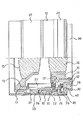
図1は上半部分を切断して示したレンズ鏡筒の側面図、図2は下半部分を切断して示した同レンズ鏡筒の側面図、図3は図1上のA−A線断面図、図4は第2固定枠を取り外して示した上記レンズ鏡筒の平面図である。
【0021】
これらの図面において、11は第1固定枠、12は第1固定枠の外枠となっている第2固定枠、13、14は第1固定枠11に対して非回動で光軸方向に移動する移動枠である。
なお、移動枠13、14は一体的に固着してあり、移動枠13には前側レンズ15を、移動枠14には後側レンズ16を各々支持させてある。
【0022】
第1固定枠11は、後部側(図1、図2において右側)が縮小径枠部となっており、その枠部に雌ねじ形のヘリコイドリング17を回転自在に、かつ、光軸方向の移動を規制して設け、このヘリコイドリング17の雌ねじを移動枠14のヘリコイドねじ(雄ねじ)に噛み合せてある。
【0023】
ヘリコイドリング17は、図1、図3に示す如く、その一部に後方向きとした凹溝18が形成してあり、この凹溝18に先端部が突入した連動レバ−19によって回動される。
連動レバ−19は、レンズ駆動リング20の後端面に固着してあり、レンズ駆動リング20の回動にしたがって旋回する。
【0024】
また、この連動レバ−19は第1固定枠11の窓孔21によって旋回範囲が定めてある。
つまり、連動レバ−19は先端側を窓孔21内で旋回するようにし、光軸周り方向の窓孔21の孔縁に当接させて旋回範囲を定めるようになっている。(図1、図4参照)
【0025】
具体的には、窓孔21の一方の孔縁(光軸周り方向の孔縁)に連動レバ−19が当るまでレンズ駆動リング20が回動したとき、レンズ15、16が無限の合焦位置に移動し、その他の孔縁に連動レバ−20が当るまでレンズ駆動リング20が回動したとき、レンズ15、16が至近の合焦位置に移動する。
このように窓孔21の孔縁がレンズ駆動リング20の回動を規制するストッパ−となっている。
【0026】
一方、第1固定枠11の後部側にはモ−タ駆動リング22が回転自在に設けてある。
このモ−タ駆動リング22は内周面に内歯車が形成してあり、この内歯車に連動歯車23(図2参照)が噛合している。
【0027】
すなわち、連動歯車23がモ−タ(図示省略)に駆動されて回転し、モ−タ駆動リング22を回動させる。
なお、連動歯車23は光軸方向に長くした細長形の歯車としてあるが、これは、移動枠13に取付けたモ−タの駆動系を連動歯車23に連結した状態で移動させるためである。
【0028】
また、モ−タ駆動リング22には、このリングの回動によって旋回する遊星歯車24が回転自在に軸着してある。なお、25は遊星歯車24の支持リングである。
この遊星歯車24は、大小径の歯車部をもった小形歯車で、大径歯車部がフォ−カス連動リング26の内歯車に噛合し、小径歯車部が上記したレンズ駆動リング20の内歯車に噛合している。
なお、フォ−カス連動リング26の内周面には内歯車が形成してある。
【0029】
遊星歯車24はモ−タ駆動力とフォ−カスリング27からの手動操作力を受ける差動機構を構成するものであり、本実施形態では図3より分かるように、モ−タ駆動リング22の3等分位置に3つの遊星歯車24が設けてある。
ただ、この遊星歯車24の個数については増減することができる。
【0030】
また、フォ−カス連動リング26は、フォ−カスリング27と一体的に固着してあり、フォ−カスリング27の回動操作によって回動し、その内歯車により遊星歯車24を回転駆動する。
【0031】
第2固定枠12は第1固定枠11に一体的に固着してあり、これには、絞りリング28、電気端子リング29、バヨネットリング30が設けてある。
【0032】
他方、このように構成したレンズ鏡筒は、フォ−カスリング27の回動を検出する検出スイッチ31が備えてある。
この検出スイッチ31は、第1固定枠11に取付けた接点端子32a、32b、32cと、フォ−カス連動リング26に設けたエンコ−ダ基板33とより構成してある。
【0033】
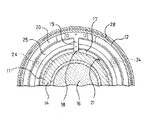
図5は検出スイッチ31を拡大して示した一部切欠き平面図で、図6はこの検出スイッチ31の動作説明図である。
図5より分かる通り、接点端子32a、32b、32cを備えた端子基体34を第1固定枠11に固着し、各々の接点端子がばね勢力でエンコ−ダ基板33に接触している。
なお、端子基体34は第1固定枠11の切欠孔35内に配設するようにしてある。
【0034】
具体的には、接点端子32a、32b、32cがコイルばね36a、36b、36cによって突出勢力を受け、これら端子先端がエンコ−ダ基板33の板面に当接している。
また、接点端子32cがア−ス端子で、接点端子32a、32bがコ−ド板部33aに接触するようになっている。
なお、エンコ−ダ基板33は、フォ−カス連動リング26の先端面の全周に設けてある。
【0035】
また、本実施形態の検出スイッチ31はスイッチのチャタリングの問題を防ぐため、コ−ド板部33aに当接させる2つの接点端子32a、32bを設け、2相のパルスとして検出信号を出力させる構成としてある。
ただ、本発明の実施に際しては、それら接点端子32a、32bのうちいずれか一つの接点端子を備えることによって実施することができる。
【0036】
その他、上記したレンズ鏡筒は、図1に示す如く、連動レバ−19に備えたブラシ端子37と第2固定枠12に設けた摺動板38によって合焦動作のレンズ位置を検出する。
なお、図2に示したブラシ端子39と摺動板40は絞り値を検出するものである。
【0037】
本実施形態のレンズ鏡筒は、自動合焦用のモ−タが測距信号にしたがって回転駆動することにより、連動歯車23が連動回転してモ−タ駆動リング22を回動する。
これより、遊星歯車24が自転しながら公転し、レンズ駆動リング20を回動させる。
【0038】
レンズ駆動リング20が回動すると、連動レバ−19が旋回し、ヘリコイドリング17を回動させ、移動枠13、14をヘリコイドねじ送りにより繰出す。
この動作によりレンズ15、16が光軸方向に移動して自動合焦が行なわれる。
【0039】
モ−タが駆動して上記のように自動合焦動作が行なわれる間、フォ−カス連動リング26が遊星歯車24の公転と自転によるモ−タ駆動力を受けるが、フォ−カス連動リング26のエンコ−ド基板33に接点端子32a、32b、32cがばね勢力で当接しているので、このリング26と一体的となっているフォ−カスリング27の回転負荷がレンズ駆動リング20の回転負荷に比べて充分に大きく、このフォ−カス連動リング26が回転しない。
言換えれば、無限位置と至近位置との間で自動合焦動作が行なわれているときは、フォ−カスリング27は回転しない。
【0040】
また、レンズ駆動リング20の回動にしたがって連動レバ−19が窓孔21の一方側の孔縁に当接し、レンズ15、16が無限の合焦位置に移動し、或いは、連動レバ−19が窓孔21の他方側の孔縁に当接し、レンズ15、16が至近の合焦位置に移動すると、窓孔21の孔縁がストッパ−となりレンズ駆動リング20の回動を停止させる。
【0041】
したがつて、その後のモ−タ回転によって、遊星歯車24を介してフォ−カス連動リング26に伝達されるモ−タ駆動力が増大し、このため、フォ−カス連動リング26が回動を始めるが、その回動が検出スイッチ31により直ちに検出される。
【0042】
このことから、検出スイッチ31の検出信号に応動する制御回路がフォ−カス連動リング26の回動初期でモ−タ駆動を停止する。
この結果、レンズ駆動リング20がストッパ−によって回動停止された場合でも、フォ−カスリング27が僅かな回動に止どまる。
【0043】
また、無限位置と至近位置との間で自動合焦動作が行なわれているときに、フォ−カスリング27が回動されると、この回動を検出スイッチ31が検出し、検出信号に応動する制御回路がモ−タ駆動を停止する。
この場合には、フォ−カスリング27を回動操作して手動により合焦させることができる。
【0044】
手動による合焦動作は、フォ−カスリング27を回動操作し、フォ−カス連動リング26を回動させる。
フォ−カス連動リング26が回動すると、その内歯車によって遊星歯車24が回転し、レンズ駆動リング20が回動する。
【0045】
これより、連動レバ−19が旋回し、ヘリコイドリング17が回動する。
この結果、移動枠13、14のヘリコイドねじ送りによりレンズ15、16を光軸方向に移動させて手動合焦させる。
【0046】
上記のように構成したレンズ鏡筒は、自動合焦動作により、レンズ駆動リング20がストッパ−に当ってモ−タ駆動が停止した場合と、自動合焦の動作中にフォ−カスリング27が不用意に回動されてモ−タ駆動が停止した場合との判断は、レンズ駆動リング20の回動を検出する検出装置(ブラシ端子37、摺動板38)の出力信号より行なうことができる。
【0047】
また、レンズ駆動リング20の回動位置により、フォ−カスリング27の回転を判断するパルス数を変化させることで、フォ−カスリング27が自動合焦動作中に不用意に回動された場合の検出に時間的なずれ(ラグ)をもたせることができる。
【0049】
また、本発明は、前側レンズ15と後側レンズ16のいずれか一方を移動させて合焦させる焦点整合機構を備えたレンズ鏡筒、或いは、ヘリコイドねじに換えてカム筒によりレンズを繰出すレンズ鏡筒についても同様に実施することができる。
【0050】
さらに、カメラ本体に合焦用モ−タを備え、このモ−タとレンズ鏡筒とをカップリングで連結してモ−タ駆動リング22を回転させる構成とすることができる。
【0051】
【発明の効果】
上記した通り、本発明のレンズ鏡筒によれば、自動合焦の動作によってレンズ駆動リングの回動がストッパ−によって停止させた関係で、フォ−カスリングが回動すると、検出スイッチの検出信号に応動する制御手段が自動合焦動作を直ちに停止する。
この結果、自動合焦においてフォ−カスリングが回転すると言う不具合がない。
【0052】
また、このレンズ鏡筒は、自動合焦の動作中にフォ−カスリングが不用意に回動されると、自動合焦動作が直ちに停止するため、フォ−カスリングが回動されたことによる自動合焦の誤差が少なくなる。
【0053】
さらに、フォ−カスリングを回動操作して手動合焦を行なう場合に、無限位置と至近位置が光学的に正確に定まる。
また、本発明のレンズ鏡筒は、自動合焦動作をしているときでも通常にカメラをホ−ルディングすることができるから、カメラの操作性に優れたレンズ鏡筒となる。
【図面の簡単な説明】
【図1】本発明の一実施形態を示し、上半部分を切断して示したレンズ鏡筒の側面図である。
【図2】下半部分を切断して示した上記レンズ鏡筒の側面図である。
【図3】図1上のA−A線断面図である。
【図4】第2固定枠を取り外して示した上記レンズ鏡筒の平面図である。
【図5】上記レンズ鏡筒に備えた検出スイッチの拡大平面図である。
【図6】上記検出スイッチの動作説明図である。
【符号の説明】
11 第1固定枠
13、14 移動枠
15 前側レンズ
16 後側レンズ
17 ヘリコイドリング
19 連動レバ−
20 レンズ駆動リング
21 ストッパ−を形成する窓孔
22 モ−タ駆動リング
23 連動歯車
24 遊星歯車
26 フォ−カス連動リング
27 フォ−カスリング
31 検出スイッチ
32a、32b、32c 接点端子
33 エンコ−ダ基板[0001]
BACKGROUND OF THE INVENTION
The present invention relates to a lens barrel for a camera provided with a focus alignment mechanism capable of performing manual focusing and automatic focusing, and in particular, when a focus ring is rotated during an automatic focusing operation. The lens barrel is configured to stop the automatic focusing operation and manually focus.
[0002]
[Prior art]
A lens barrel for a camera equipped with a focus alignment mechanism capable of performing manual focusing and automatic focusing is not provided with a switching means in addition to one that switches between manual focusing and automatic focusing to perform focusing operation. There is a configuration in which manual focusing and automatic focusing are performed by interposing one differential mechanism.
[0003]
The focus alignment mechanism including the differential mechanism includes a motor drive ring that is driven by a motor and acts as an arm gear, and a planetary gear that is pivotally supported by the drive ring.
[0004]
In the case of automatic focusing, the lens driving ring is rotated in conjunction with the revolution and rotation of the planetary gear by the rotation of the motor driving ring, the lens is moved to the focusing position, and manual focusing is performed. In this case, the driving force of the focus ring is applied to the planetary gear, the lens driving ring is rotated in conjunction with the rotation of the planetary gear, and the lens is moved to the in-focus position.
[0005]
Therefore, such a focus matching mechanism using a differential mechanism is connected to the planetary gear because the motor interlocking system and the focus ring interlocking system are connected to each other during the automatic focusing of the motor drive. The motor driving force transmitted to the planetary gear is transmitted to the focus ring in addition to the lens driving ring.
[0006]
For this reason, in order to prevent the focus ring from rotating during the automatic focusing operation, a friction mechanism is provided in the focus ring and its interlocking gear train.
[0007]
That is, friction that overcomes the interlocking force applied to the focusing ring from the planetary gear during the automatic focusing operation is given to the focusing ring so that the focusing ring is not rotated during the automatic focusing operation.
[0008]
[Problems to be solved by the invention]
In the above-described focus alignment mechanism, the lens drive ring is rotated by the automatic focusing operation, and when the lens drive ring hits the stopper at the infinite position (∞ position) or the closest position, the lens drive ring cannot be rotated. Most of the transmitted motor driving force is applied to the focus ring, and therefore the focus ring rotates as the planetary gear rotates.
[0009]
In order to solve this problem, the position of the lens drive ring is shifted so that the rotation amount of the lens drive ring is larger than the original stopper position that stops the rotation of the lens drive ring at the infinite position and the close position. A configuration means is adopted in which the rotation of the infinite position or the closest position is electrically detected, the automatic focusing motor is stopped and controlled according to the detection before the ring hits the stopper, and the focus ring is not rotated. ing.
[0010]
However, even if such a configuration means can prevent the focusing ring from rotating due to automatic focusing, the stopper ring position of the lens driving ring is not close to the original infinite position. When operating and focusing, the infinite position and the closest position of the lens drive ring cannot be determined.
[0011]
That is, there is a problem that it is difficult to set the lens position to the infinite position or the closest position in manual focusing by the focusing ring turning operation.
[0012]
On the other hand, when the focus ring is inadvertently operated while the motor is in autofocus operation, it is detected that the hand touches the focus ring, and the motor is operated in response to this detection signal. There has been proposed a lens barrel that is configured to stop and end the automatic focusing operation.
[0013]
However, this lens barrel is extremely inconvenient for holding the camera because it cannot touch the focus ring of the lens barrel when holding the camera for automatic focusing. .
For this reason, the focus ring is made small so that the hand cannot be touched. However, with this configuration, it is difficult to operate the focus ring when manually operating the focus ring and performing manual focusing. It will be a thing.
[0014]
A stopper that mechanically stops the rotation of the lens drive ring at an infinite position and a close position of the lens; a focus interlocking ring that rotates integrally with the focus ring; and the focus fixed to interlocking rings, diene was provided along its ring - provided da substrate and the barrel fixing frame, the diene tip side spring force - has a contact terminal which is brought into contact with da substrate, the diene - with giving constantly load Kasuringu, the follower - - the follower by the contact force of the contact terminals abuts the da substrate and detection switch for detecting from da substrate and the contact terminal, - the rotation of the dregs interlocking rings diene When the focus ring is rotated by receiving the output of the differential mechanism as the rotation of the lens driving ring by the automatic focusing operation is stopped by the stopper. Has a configuration in which a control means for stopping an automatic focusing operation in response to the detection signal of the detection switch.
[0015]
[Means for Solving the Problems]
In order to achieve the above-described object, the present invention provides a lens in conjunction with a lens drive ring that rotates in response to an output of a differential mechanism that connects a focus ring drive system and a motor drive system. The present invention relates to a camera lens barrel that includes a moving focus matching mechanism and performs manual focusing for focusing operation and automatic focusing by motor driving via the differential mechanism.
[0016]
A stopper that mechanically stops the rotation of the lens driving ring at the infinite position and the closest position of the lens;
A focus interlocking ring that rotates integrally with the focus ring;
An encoder substrate fixed to the focus interlocking ring along the ring and a lens barrel fixing frame; and a contact terminal abutted against the encoder substrate by a spring force, the encoder substrate A detection switch that constantly applies a load to the focus ring by the contact force of the contact terminal that contacts the substrate, and detects rotation of the focus interlocking ring;
When the focus ring is rotated by receiving the output of the differential mechanism as the rotation of the lens drive ring by the automatic focusing operation is stopped by the stopper, the detection switch detects Control means for stopping the automatic focusing operation in response to the signal is provided.
[0017]
[Action]
In the lens barrel of the present invention, if the focus ring rotates during the automatic focusing operation, the control means that responds to the detection signal of the detection switch stops the automatic focusing operation.
[0018]
Therefore, for example, when the lens driving ring hits the stopper at the infinite focusing position or the closest focusing position by the automatic focusing operation, and the focusing ring rotates, the control means that responds to the detection signal is immediately automatically focused. In order to stop the focusing operation, the focus ring rotates slightly and stops.
[0019]
If the focus ring rotates during the automatic focusing operation, the automatic focusing operation is stopped, and then manual focusing becomes possible.
For this reason, there is no problem in camera holding and focusing operations.
[0020]
DETAILED DESCRIPTION OF THE INVENTION
Next, embodiments of the present invention will be described with reference to the drawings.
1 is a side view of the lens barrel shown by cutting the upper half portion, FIG. 2 is a side view of the lens barrel shown by cutting the lower half portion, and FIG. 3 is an AA line in FIG. FIG. 4 is a cross-sectional view, and FIG. 4 is a plan view of the lens barrel shown with the second fixed frame removed.
[0021]
In these drawings, 11 is a first fixed frame, 12 is a second fixed frame which is an outer frame of the first fixed frame, and 13 and 14 are non-rotating with respect to the first fixed
The
[0022]
The first fixed
[0023]
As shown in FIGS. 1 and 3, the
The interlocking
[0024]
The interlocking
That is, the interlocking
[0025]
Specifically, when the
Thus, the hole edge of the
[0026]
On the other hand, a
The
[0027]
That is, the interlocking
The interlocking
[0028]
Further, a
This
An internal gear is formed on the inner peripheral surface of the
[0029]
The
However, the number of the
[0030]
Further, the
[0031]
The second fixed
[0032]
On the other hand, the lens barrel configured as described above includes a
The
[0033]
FIG. 5 is a partially cutaway plan view showing the
As can be seen from FIG. 5, a
The
[0034]
Specifically, the
The
The
[0035]
In addition, the
However, the present invention can be implemented by providing any one of the
[0036]
In addition, the lens barrel described above detects the lens position of the focusing operation by the
Note that the brush terminal 39 and the sliding
[0037]
In the lens barrel of the present embodiment, the motor for automatic focusing is driven to rotate according to the distance measurement signal, whereby the interlocking
As a result, the
[0038]
When the
By this operation, the
[0039]
Mode - While data is driven automatic focusing operation as described above is performed, follower - but subjected to motor driving force, follower - -
In other words, the
[0040]
Further, as the
[0041]
Therefore, the motor driving force transmitted to the
[0042]
Thus, the control circuit that responds to the detection signal of the
As a result, even when the
[0043]
When the focusing
In this case, the
[0044]
In the manual focusing operation, the
When the
[0045]
As a result, the interlocking
As a result, the
[0046]
In the lens barrel configured as described above, when the
[0047]
In addition, by detecting the rotation position of the
[0049]
The present invention also provides a lens barrel provided with a focus alignment mechanism that moves and focuses either the
[0050]
Further, a focusing motor can be provided in the camera body, and the
[0051]
【The invention's effect】
As described above, according to the lens barrel of the present invention, when the focus ring rotates in a relationship where the rotation of the lens drive ring is stopped by the stopper by the automatic focusing operation, the detection signal of the detection switch is output. The responding control means immediately stops the automatic focusing operation.
As a result, there is no problem that the focus ring rotates during automatic focusing.
[0052]
In addition, if the lens ring is inadvertently rotated during the automatic focusing operation, the automatic focusing operation stops immediately, so that the automatic focusing due to the rotation of the focusing ring is stopped. There is less error in focus.
[0053]
Further, when manual focusing is performed by rotating the focus ring, the infinite position and the closest position are optically accurately determined.
Further, the lens barrel of the present invention can normally hold the camera even during the automatic focusing operation, so that the lens barrel is excellent in camera operability.
[Brief description of the drawings]
FIG. 1 is a side view of a lens barrel showing an embodiment of the present invention, with an upper half portion cut away.
FIG. 2 is a side view of the lens barrel shown with a lower half portion cut away.
3 is a cross-sectional view taken along line AA in FIG.
FIG. 4 is a plan view of the lens barrel with the second fixed frame removed.
FIG. 5 is an enlarged plan view of a detection switch provided in the lens barrel.
FIG. 6 is an operation explanatory diagram of the detection switch.
[Explanation of symbols]
11 First fixed
20
Claims (1)
レンズの無限位置と至近位置とで前記レンズ駆動リングの回動を機械的に停止させるストッパ−と、
前記フォ−カスリングと一体的に回動するフォ−カス連動リングと、
前記フォ−カス連動リングに固着し、そのリングに沿うように設けたエンコ−ダ基板及び鏡筒固定枠に設け、先端側をばね勢力で前記エンコ−ダ基板に当接させた接点端子を有し、前記エンコ−ダ基板に当接する前記接点端子の当接力により前記フォ−カスリングに常時負荷を与えると共に、前記フォ−カス連動リングの回動を前記エンコ−ダ基板と前記接点端子より検出する検出スイッチと、
自動合焦動作による前記レンズ駆動リングの回動が前記ストッパ−によって停止されることに伴って、前記フォ−カスリングが前記差動機構の出力を受けて回動するときは、前記検出スイッチの検出信号に応動して自動合焦動作を停止させる制御手段とを設けたことを特徴とする焦点整合機構を備えたカメラ用レンズ鏡筒。A focusing mechanism that moves a lens in conjunction with a lens driving ring that rotates in response to an output of a differential mechanism that connects a focusing ring driving system and a motor driving system; In a lens barrel for a camera that performs manual focusing for focusing operation and automatic focusing by motor driving,
A stopper that mechanically stops the rotation of the lens driving ring at an infinite position and a close position of the lens;
A focus interlocking ring that rotates integrally with the focus ring;
Said follower - fixed to Kas interlocking rings, diene was provided along its ring - provided Da substrate and the barrel fixing frame, said distal side by a spring force ene - have a contact terminal which is brought into contact with da substrate and, wherein the diene - with giving constantly load Kasuringu, the follower - - the follower by the contact force of the contact terminals abuts da substrate wherein the rotation of the dregs interlocking ring ene - detecting than da substrate and the contact terminal A detection switch;
When the focus ring is rotated by receiving the output of the differential mechanism as the rotation of the lens drive ring by the automatic focusing operation is stopped by the stopper, the detection switch detects A lens barrel for a camera provided with a focus matching mechanism, characterized in that control means for stopping an automatic focusing operation in response to a signal is provided.
Priority Applications (1)
| Application Number | Priority Date | Filing Date | Title |
|---|---|---|---|
| JP25764798A JP3849111B2 (en) | 1998-08-28 | 1998-08-28 | Camera lens barrel with focus alignment mechanism |
Applications Claiming Priority (1)
| Application Number | Priority Date | Filing Date | Title |
|---|---|---|---|
| JP25764798A JP3849111B2 (en) | 1998-08-28 | 1998-08-28 | Camera lens barrel with focus alignment mechanism |
Publications (2)
| Publication Number | Publication Date |
|---|---|
| JP2000075194A JP2000075194A (en) | 2000-03-14 |
| JP3849111B2 true JP3849111B2 (en) | 2006-11-22 |
Family
ID=17309162
Family Applications (1)
| Application Number | Title | Priority Date | Filing Date |
|---|---|---|---|
| JP25764798A Expired - Fee Related JP3849111B2 (en) | 1998-08-28 | 1998-08-28 | Camera lens barrel with focus alignment mechanism |
Country Status (1)
| Country | Link |
|---|---|
| JP (1) | JP3849111B2 (en) |
Families Citing this family (1)
| Publication number | Priority date | Publication date | Assignee | Title |
|---|---|---|---|---|
| JP5214549B2 (en) * | 2009-07-03 | 2013-06-19 | Hoya株式会社 | Rotating feeding structure of lens barrel |
-
1998
- 1998-08-28 JP JP25764798A patent/JP3849111B2/en not_active Expired - Fee Related
Also Published As
| Publication number | Publication date |
|---|---|
| JP2000075194A (en) | 2000-03-14 |
Similar Documents
| Publication | Publication Date | Title |
|---|---|---|
| US7672579B2 (en) | Retractable lens barrel | |
| EP0273381B1 (en) | Focal length switchover camera | |
| US7388722B2 (en) | Lens barrel incorporating a rotatable optical element | |
| US6813441B2 (en) | Lens drive system | |
| US20060274430A1 (en) | Retractable lens barrel | |
| US4621906A (en) | Auto-focus zoom lens assembly | |
| JPH05215951A (en) | Encoder device | |
| JP3849111B2 (en) | Camera lens barrel with focus alignment mechanism | |
| JP2521242Y2 (en) | Camera shutter device | |
| JPH04226441A (en) | Camera | |
| JPH08234075A (en) | Zoom lens barrel | |
| JPH10115760A (en) | Lens barrel | |
| JPH09211299A (en) | Lens barrel with built-in ultrasonic motor | |
| JPH0736338Y2 (en) | Camera lens barrel | |
| JP4012001B2 (en) | Lens barrel and camera | |
| JP2524368B2 (en) | Manual focusing operation device | |
| JP2533650Y2 (en) | Shutter for zoom lens | |
| JP3835743B2 (en) | camera | |
| JP2000075193A (en) | Camera lens barrel equipped with focusing mechanism | |
| JPH04343310A (en) | Lens barrel containing surface wave motor | |
| JPH08313793A (en) | Lens operating device | |
| JPH087379Y2 (en) | Zoom lens encoder | |
| JP2732507B2 (en) | camera | |
| JP4100950B2 (en) | Camera focus drive | |
| JPH07306354A (en) | Lens barrel |
Legal Events
| Date | Code | Title | Description |
|---|---|---|---|
| A977 | Report on retrieval |
Free format text: JAPANESE INTERMEDIATE CODE: A971007 Effective date: 20040119 |
|
| A131 | Notification of reasons for refusal |
Effective date: 20040127 Free format text: JAPANESE INTERMEDIATE CODE: A131 |
|
| A521 | Written amendment |
Effective date: 20040325 Free format text: JAPANESE INTERMEDIATE CODE: A523 |
|
| A02 | Decision of refusal |
Free format text: JAPANESE INTERMEDIATE CODE: A02 Effective date: 20040511 |
|
| A521 | Written amendment |
Effective date: 20040709 Free format text: JAPANESE INTERMEDIATE CODE: A523 |
|
| A911 | Transfer of reconsideration by examiner before appeal (zenchi) |
Free format text: JAPANESE INTERMEDIATE CODE: A911 Effective date: 20040917 |
|
| A912 | Removal of reconsideration by examiner before appeal (zenchi) |
Free format text: JAPANESE INTERMEDIATE CODE: A912 Effective date: 20041022 |
|
| A61 | First payment of annual fees (during grant procedure) |
Free format text: JAPANESE INTERMEDIATE CODE: A61 Effective date: 20060818 |
|
| R150 | Certificate of patent (=grant) or registration of utility model |
Free format text: JAPANESE INTERMEDIATE CODE: R150 |
|
| FPAY | Renewal fee payment (prs date is renewal date of database) |
Free format text: PAYMENT UNTIL: 20100908 Year of fee payment: 4 |
|
| FPAY | Renewal fee payment (prs date is renewal date of database) |
Year of fee payment: 4 Free format text: PAYMENT UNTIL: 20100908 |
|
| FPAY | Renewal fee payment (prs date is renewal date of database) |
Year of fee payment: 5 Free format text: PAYMENT UNTIL: 20110908 |
|
| FPAY | Renewal fee payment (prs date is renewal date of database) |
Year of fee payment: 5 Free format text: PAYMENT UNTIL: 20110908 |
|
| FPAY | Renewal fee payment (prs date is renewal date of database) |
Free format text: PAYMENT UNTIL: 20120908 Year of fee payment: 6 |
|
| LAPS | Cancellation because of no payment of annual fees |