JP3848945B2 - Variable width roll forming equipment - Google Patents
Variable width roll forming equipment Download PDFInfo
- Publication number
- JP3848945B2 JP3848945B2 JP2003516715A JP2003516715A JP3848945B2 JP 3848945 B2 JP3848945 B2 JP 3848945B2 JP 2003516715 A JP2003516715 A JP 2003516715A JP 2003516715 A JP2003516715 A JP 2003516715A JP 3848945 B2 JP3848945 B2 JP 3848945B2
- Authority
- JP
- Japan
- Prior art keywords
- die assembly
- side plate
- collector plate
- roll forming
- roller
- Prior art date
- Legal status (The legal status is an assumption and is not a legal conclusion. Google has not performed a legal analysis and makes no representation as to the accuracy of the status listed.)
- Expired - Lifetime
Links
- 230000007246 mechanism Effects 0.000 claims description 27
- 230000000712 assembly Effects 0.000 claims description 15
- 238000000429 assembly Methods 0.000 claims description 15
- 238000000034 method Methods 0.000 claims description 13
- 238000006073 displacement reaction Methods 0.000 claims description 12
- 239000000463 material Substances 0.000 claims description 4
- 238000000465 moulding Methods 0.000 claims description 3
- 230000000750 progressive effect Effects 0.000 claims description 2
- 238000000926 separation method Methods 0.000 claims description 2
- 230000008878 coupling Effects 0.000 claims 5
- 238000010168 coupling process Methods 0.000 claims 5
- 238000005859 coupling reaction Methods 0.000 claims 5
- 230000015572 biosynthetic process Effects 0.000 description 4
- 238000005755 formation reaction Methods 0.000 description 4
- 230000008859 change Effects 0.000 description 3
- 239000002184 metal Substances 0.000 description 3
- 238000005452 bending Methods 0.000 description 2
- 230000009286 beneficial effect Effects 0.000 description 2
- 230000008901 benefit Effects 0.000 description 2
- 230000000694 effects Effects 0.000 description 2
- 238000011144 upstream manufacturing Methods 0.000 description 2
- 230000009918 complex formation Effects 0.000 description 1
- 238000012937 correction Methods 0.000 description 1
- 238000013461 design Methods 0.000 description 1
- 230000003993 interaction Effects 0.000 description 1
- 238000012986 modification Methods 0.000 description 1
- 230000004048 modification Effects 0.000 description 1
- 230000008569 process Effects 0.000 description 1
- 230000009467 reduction Effects 0.000 description 1
- 238000012552 review Methods 0.000 description 1
- 238000007493 shaping process Methods 0.000 description 1
Images


Classifications
-
- B—PERFORMING OPERATIONS; TRANSPORTING
- B21—MECHANICAL METAL-WORKING WITHOUT ESSENTIALLY REMOVING MATERIAL; PUNCHING METAL
- B21D—WORKING OR PROCESSING OF SHEET METAL OR METAL TUBES, RODS OR PROFILES WITHOUT ESSENTIALLY REMOVING MATERIAL; PUNCHING METAL
- B21D5/00—Bending sheet metal along straight lines, e.g. to form simple curves
- B21D5/06—Bending sheet metal along straight lines, e.g. to form simple curves by drawing procedure making use of dies or forming-rollers, e.g. making profiles
- B21D5/08—Bending sheet metal along straight lines, e.g. to form simple curves by drawing procedure making use of dies or forming-rollers, e.g. making profiles making use of forming-rollers
Description
本発明は、一般に、複数の整合するダイロール(matching die rolls)にウェブ(web)を通過させることで、シート材料からなる連続的なウェブを成形可能な可変幅ロール成形装置に関するものであり、より詳細には、整合するダイロール間の間隔(spacing)を変更可能であり、同様にウェブの幅のバリエーションに対し補正可能である可変幅ロール成形装置に関するものである。 The present invention generally relates to a variable width roll forming apparatus capable of forming a continuous web of sheet material by passing the web through a plurality of matching die rolls, and more In particular, the present invention relates to a variable width roll forming apparatus that can change the spacing between the matching die rolls and can also correct for variations in web width.
公知であるロール成形機械は、普通、ロールダイ(roll dies)の複数のセットを備え、それらロールダイは、通常、アッパーとロアーの整合するペア(pairs)として配置されると共に、一般に、ローラースタンド(roller stands)上の機械の長手方向(the length)に沿って間隔を隔て配置される。通常、一つのスタンドのローラーダイがウェブに連続的な形状(形成物:formation)を形成し、次のスタンドのローラーダイが、異なる形状を形成するか、若しくは、例えば、一つ前のスタンドなどにより既に着手された形状の角度を増加させる。 Known roll forming machines typically include multiple sets of roll dies, which are usually arranged as matched pairs of upper and lower and generally are roller stands. It is spaced along the length of the machine on the stands. Usually, the roller die of one stand forms a continuous shape (formation) on the web and the roller die of the next stand forms a different shape or, for example, the previous stand, etc. To increase the angle of the shape already undertaken.
数多くの消費者用品(consumer equipment)の構成要素と同様に、屋根を飾る羽目板(roof decking siding)などの幅広い種類の工業用又は他の用途の製品が、そのようなロール成形機により製造される。その形状は、一端若しくは両端に沿って形成される単なる端部形成物(edge formations)であり、又は、C状断面若しくはU状断面であり、しかし多くの場合、ウェブの長手方向に沿って並び形成される縦の形成物を含む、比較的複雑な形成物からなるものである。 A wide variety of industrial or other application products, such as roof decking siding, as well as many consumer equipment components are produced by such roll forming machines. . The shape is simply edge formations formed along one or both ends, or a C-shaped or U-shaped cross section, but often aligned along the longitudinal direction of the web It consists of relatively complex formations, including vertical formations that are formed.
概して、ロール(rolls)の各スタンドには、ウェブの中心線の両側に様々な曲げや形状を形成するための、ペア(pairs)に配置された二つのロアーダイと二つのアッパーダイがある。それらロアーダイがウェブの下面と係合し、それらアッパーダイがウェブの上面と係合する。ダイは円形の形状を有し、さらに、ダイが金属薄板(sheet metal)と同じ速度で回転可能なように、ダイは、回転可能な軸に設けられる。ダイを金属薄板の速度で駆動するためのギア駆動機構が、ダイに連結される。 In general, each stand of rolls has two lower dies and two upper dies arranged in pairs to form various bends and shapes on either side of the web centerline. The lower dies engage the lower surface of the web and the upper dies engage the upper surface of the web. The die has a circular shape and is further provided on a rotatable shaft so that the die can rotate at the same speed as the sheet metal. A gear drive mechanism for driving the die at the speed of the thin metal plate is coupled to the die.
そのようなローラーダイの各セットは、ウェブに特定の形成物をもたらすように設計されなければならない。加えて、ダイの各ペアは、それらの間に、ウェブの厚さにより決定される隙間を有しなければならない。 Each set of such roller dies must be designed to give a specific formation to the web. In addition, each pair of dies must have a gap between them determined by the thickness of the web.
従って、一つの厚さを有するウェブに対しての作業を停止し、その後異なる厚さを有するウェブをダイに通過させることが望まれる場合、新しいウェブの新しい厚さに適応するように、ダイの各ペアを新しい隙間へと再調整しなければならない。これには普通、これらの微調整を行うための手動による操作とコストのかかる停止時間を必要とする。 Thus, if it is desired to stop working on a web with one thickness and then pass a web with a different thickness through the die, the die can be adjusted to accommodate the new thickness of the new web. Each pair must be readjusted to a new gap. This usually requires manual operation and costly downtime to make these fine adjustments.
従って、各スタンドにおけるダイのペア間の間隔又は隙間に対する、自動化された自動調整(self-adjustment)が提供されることが望ましい。しかしながら、ダイの形状のために、そのような調整には、幾つかの困難を伴う。普通ダイは、二つの面を有し、一つの面は、略水平若しくは少なくともウェブの平面に平行であり、他方の面は、ウェブの形成角(web-forming angle)をなす。 Accordingly, it is desirable to provide automated self-adjustment for the spacing or gap between die pairs on each stand. However, due to the shape of the die, such adjustment involves some difficulties. A typical die has two faces, one face being substantially horizontal or at least parallel to the plane of the web, and the other face forming a web-forming angle.
前のウェブよりも広い幅や狭い幅を有するウェブを形成する際に、同じローラーダイを用いようとするならば、別の問題が生じる。 Another problem arises when trying to use the same roller die in forming a web having a wider or narrower width than the previous web.
従来は、処理される新しいウェブの幅を考慮し、ウェブの両側に位置する各スタンドを、遠く離れるように或いは、互いに近づくように手動で動かす必要があった。しかしながら、容易に確認されるように、一つのウェブの幅に適したダイの配置を分解し、その後、新しいウェブの幅に適合するように、それらの間に多少の数のロールを含むダイを再び組み立てるのには、多くの時間を要した。加えて、これは、手間がかかり時間を消費する人力作業であった。 In the past, considering the width of the new web being processed, it was necessary to manually move the stands located on either side of the web away from each other or closer together. However, as can easily be seen, the die arrangement suitable for the width of one web is disassembled, and then a die containing a few rolls between them to fit the width of the new web. It took a lot of time to reassemble. In addition, this was a labor intensive and time consuming work.
特許文献1により、幾つかのロール成型機の実施の形態が示される。そのロール成型機は、異なるゲージのウェブに適応するために、所定のローラースタンドのダイからなる整合するペア間の相対的な方向付け(orientation)を素早く調整可能である。同様にウェビング(ウェブ)の両側のローラースタンドのグループを、遠く離れるように或いは、互いに近づくように移動させるための自動化された手順が明らかされる。特許文献1を参照することにより、その全体の内容が本願に組み入れられることとする。 Patent Document 1 shows several embodiments of a roll forming machine. The roll forming machine can quickly adjust the relative orientation between matching pairs of predetermined roller stand dies to accommodate different gauge webs. Similarly, an automated procedure for moving a group of roller stands on either side of a webbing (web) away or closer to each other is revealed. By referring to Patent Document 1, the entire contents thereof are incorporated in the present application.
特許文献1と図1とから明らかなように、各々が86と82であるロールダイの整合するペアの内、アッパーロールダイ86は、ある回転のために、偏心スリーブ90内に固定され、偏心スリーブ90がその回転を行うと、アッパーロールダイ86が、整合するロアーダイ82に対し垂直に関係し移動する。より詳細には、複数のロアーダイドライブシャフト80が、適切な軸受により、ロール成形機のサイドプレート38内に直接支持される。これらのドライブシャフトは、適切なギア列により駆動されると共にロアーフォーミングダイ82を支持する。テレスコーピングドリブンシャフト(Telescoping driven shafts)84は、ドライブシャフト80から、ドリブンハブ(driven hubs)(図示せず)まで延び、ドリブンハブは、ウェビングWの反対側に配置される整合するサイドプレート(side plates)の中に回転可能に設けられる。ドリブンシャフト84は、これらのドリブンハブまで完全に達する。ロアーフォーミングダイ82が、そのようなドリブンハブにより支持される。このようして、ロール成形機内の全てのスタンドのロアーフォーミングダイが、調和して駆動される。
As is apparent from US Pat. No. 6,057,056 and FIG. 1, of the matching pairs of roll dies, 86 and 82, respectively, the
複数のアッパーダイ86がアッパーシャフト88により支持される。アッパーシャフト88を支持する偏心軸受スリーブ90はスライド可能(slidably)かつ回転可能(rotatably)に、サイドプレート38内に設けられる。後述する理由により、スリーブ90は、スリーブ90の中心軸からずれたシャフト開口部92を定義(define)する。アッパーダイシャフト88は、ロアーシャフトに接続されるギア列により、それ自身駆動される。上での説明により、各々86と82である、アッパー及びロアーダイの内少なくとも一方を他方に対し相対的に調整するための手段が提供される。従って、ウェブ材Wの厚さ又はゲージと出来るだけ厳密に釣り合うように、ダイ間の垂直方向の隙間が調整される。そのような調整は、ウェブWが実際にダイ間を通る間に行われる。従って、その長手方向に沿うウェブの厚さのバリエーションに対する補正がなされる。これら全ては、後に詳述される。
A plurality of
アッパーダイ86は、固定軸上のロアーダイ82と相対的に全て調整できることが理解される。しかしながら、容易に理解されるように、もしそのような構成が望まれるならば、アッパーダイ86を固定のままで、ロアーダイ82を調整可能とすることもできる。
It will be appreciated that the
上で説明したように、各アッパーシャフトスリーブ90は、ダイシャフト88とドリブンハブ(図示しない)を、サイドプレート38内に受けるための偏心シャフト開口部92を有する。各スリーブ90は、サイドプレート38内の各開口部により支持される。
As described above, each
スリーブ90は、サイドプレート38内で回転可能であり、後述されるように、スリーブ90が、アッパーダイシャフト88とそれらのダイ86の略弧状(arcuate)の移動を、引き起こす。
The
スリーブ90は、また軸方向(つまり、水平方向で、内側向きや外側向き)に調整可能であり、これは結局、ウェブWと相対的に斜めの軸に沿った、アッパーダイ86の調整を生み出し、ウェブの厚さに関する小さなバリエーションに適応する。そのウェブは、水平に対向する各ダイペアの面を通り、同様に角を有し(angularly)対向する各ダイペアの面も通る。
The
この調整を達成するための機構もまた、図1に示される。図1を再び参照すると、各スレーブ90は、略弧状の偏心アーム60に接続される。二つのボルト62は、アーム60のアーチ状(arcuate)スロット64を通ると共にスリーブ90内にねじ止めされる。その偏心アーム60には、上向きのガイド66のペアが形成され、それらがU字状スロットを定義する。調整ピン68が、ガイド66からなるU字状スロット内に受けられる。そのピン68は、サイドプレート38の上部に沿って延びる調整又はドローバー61から横に延びる。ウェブWの反対側に位置するサイドプレート内に設けられた反対側のスリーブ(図示せず)にも、同様の構造が提供される。図示しない整合するサイドプレートの上部に沿って、同様のドローバーが延びることが理解されるであろう。
A mechanism for achieving this adjustment is also shown in FIG. Referring back to FIG. 1, each
それらピン68は、ドローバー61に沿い一定間隔(spaced intervals)をおき、スリーブ90の位置と対応する間隔で配置される。バー61の一端に配置される適切な動力機構(図示せず)がそれを押す又は引くことで、調整のための移動が供給される。バー61が移動すると、ガイド66の間に位置するピン68が、アーム60を、狭い角度の範囲内で回転させる。多くの場合、一度か二度の弧で十分である。これにより、次に、スリーブ90が同じ弧で回転する。スリーブ90が、偏心的方法により、ダイシャフト88を中心から離れるように移動させることで、シャフト88が上方又は下方にわずかな量だけ振れる。その量は、ウェブの厚さのバリエーションに対する調整を行うのに十分である。
The pins 68 are spaced apart along the
これにより、ロアーダイ82と相対的な、アッパーダイ86の垂直及び横方向の調整が、説明される。
This explains the vertical and lateral adjustment of the
シャフトの軸に沿っての水平方向の調整も、図1に示される機構により提供される。これは、サイドプレート38に固定されたカムブロック67と、アーム60にねじ止めされたコオペレーティングローラー63とにより生み出される。
Horizontal adjustment along the axis of the shaft is also provided by the mechanism shown in FIG. This is produced by a
ブロック67には、一般に(generally)斜めのスロット65が形成され、それが、ローラー63を受ける。僅かな角度の調整を行うように、ピン68がアーム60を移動させた際、それにより、ローラー63も、スロット65に沿って移動する。スロット65の軸は、斜めの軸に沿うよう傾けられ、従って、ローラー63はその傾いた軸に沿い移動する。これにより、アーム60は、サイドプレート38に向かうように、或いは遠ざかるように移動する。従って、アーム60が取り付けられたスリーブ90は、プレート38の内側或いは外側に向かいスライドする。繰り返すと、実際に移動する程度は僅かであるが、しかし、ウェブの厚さのバリエーションに適応するために必要とされる、ダイの隙間の調整を行うのに十分である。
それにより、ローラー63とスロット65によりアーム60が移動することで、ガイド66は、ピン68と相対的に、外向きに或いは内向きにスライドする。しかし繰り返すと、移動の程度は僅かである。従って、単一のドローバー61によりこの機構が作動することで、スリーブ90が、その軸を横断する方向とその軸に沿う軸方向の両方向に対し同時に移動する。即ち、それは、ロアーダイ82とサイドプレート38に関して、垂直方向と水平方向の両方である。これらの二つの移動の程度が、ロアーダイ82と相対的な、アッパーダイ86の斜めの軸に沿った移動へと換算される。ボルト62は緩めること可能であり、アーム60は、スロット64をボルトと相対的にスライドさせることで、調整可能であり、そのボルトは、その後再び締めることが可能である。これにより、運転に先立ち、特定のウェブの厚さに対しダイの隙間が最適となるように、機械をセットアップすることが可能となる。容易に理解されるように、図1に示される機構について、より完全な運転上の理解が、前に論じたように、特許文献1の調査により確認され、それを参照することにより、その全体の内容が本願に組み入れられることする。
Thereby, the
図1と共に上で詳述したように、ウェブの厚さ又はゲージに関する変更が、偏心的に一列に整列されたアッパー(又はロアー)ロールダイをカミング(camming)配置と共に用いることで、容易に適応される。一方、ウェブの幅に関する著しい変更は、それ自身、必要に合わせ、多くの対向するサイドプレートの内の一つを、他方から離れるように或いは他方に向かうようにシフトするよう作動する駆動機構を用いることで補正される。それにより、ロール成形装置の指定された部分の幅が選択的に調整される。 As detailed above in conjunction with FIG. 1, changes in web thickness or gauge are easily accommodated by using an eccentrically aligned upper (or lower) roll die with a camming arrangement. The On the other hand, a significant change in the width of the web itself uses a drive mechanism that operates to shift one of many opposing sideplates away from or toward the other as needed. This is corrected. Thereby, the width of the designated portion of the roll forming apparatus is selectively adjusted.
しかしながら、注意すべき重要なことであるが、上で詳述したロール成形装置は、普通幾つかの、運転上統合されたステーション若しくは、ダイスタンドのセットから構成され、それらは、移動するウェブの両側に配置される整合する複数の各々異なるサイドプレート内に収容される。ロール成形装置の異なるステーションが、異なる幅のウェブに適応するよう配置可能であるためには、そのような構成が必要であり、その際、ウェブは、ロール成形装置の端から端まで進行する。従って、ロール成形装置は普通、ウェブがロール成形装置の端から端までを進行する際に、ウェブの幅の変更に適応するように、1番目の幅に設定された1番目のステーションのための対向するサイドプレートのセットと、2番目の幅に設定された2番目のステーションのための他のサイドプレートのセットと、3番目の幅に設定された3番目のステーションのための又別のサイドプレートのセットなどを、必要とする。 It is important to note, however, that the roll forming apparatus detailed above usually consists of several sets of operationally integrated stations or die stands, which are used for moving webs. It is accommodated in a plurality of matching different side plates arranged on both sides. Such a configuration is necessary in order that different stations of the roll forming device can be arranged to accommodate different width webs, with the web traveling from end to end of the roll forming device. Thus, a roll forming device is usually for a first station set to the first width to accommodate changes in the width of the web as it travels from end to end of the roll forming device. A set of opposing side plates, another set of side plates for the second station set to the second width, and another side for the third station set to the third width A set of plates is required.
従って、上述したロール成形装置の主な欠点は、ウェブの両側に配置される単一のサイドプレートを用いることができないことであり、それにより、装置全体の剛性と安定性が低くなる。さらに、ロール成形装置の個々に分かれたステーションは、各々が対向するサイドプレートを有し、それらステーションを、全体として一列に並べることは、これらステーションに関しての、コーディネーションの複雑性と同様にアライメントの複雑性を著しく増加させる。 Therefore, the main drawback of the roll forming apparatus described above is that it is not possible to use a single side plate placed on both sides of the web, thereby reducing the rigidity and stability of the entire apparatus. In addition, the individual stations of the roll forming apparatus each have opposing side plates and aligning the stations as a whole is a complex alignment as well as the coordination complexity for these stations. Significantly increase sex.
本発明の目的は、より高い剛性と安定性を示すロール成形装置を構成することである。 An object of the present invention is to configure a roll forming apparatus that exhibits higher rigidity and stability.
本発明の他の目的は、ロール成形装置の全長に沿って配置された一組の対向するサイドプレートを有するロール成形装置を構成することである。 Another object of the present invention is to construct a roll forming apparatus having a pair of opposing side plates disposed along the entire length of the roll forming apparatus.
本発明の他の目的は、対向するサイドプレート(sides plates)の全体をシフトさせることなく、選択されたダイスタンド(die stands)のペア(pairs)間の幅を操作することである。 Another object of the present invention is to manipulate the width between selected die stands pairs without shifting the entire opposing side plates.
本発明の他の目的は、アッパー及びロアーダイのペア間の所望の関係を維持したままに、対向するサイドプレートの全体をシフトさせることなく、選択されたダイスタンドのペア間の幅を操作することである。 Another object of the present invention is to manipulate the width between selected pairs of die stands without shifting the entire opposing side plate while maintaining the desired relationship between the upper and lower die pairs. It is.
本発明の好適な一実施形態によると、可変幅ロール成形装置は、それを通るように向けられたウェブ材料を漸次成形するためものであり、その可変幅ロール成形装置は、ロール成形装置の略全長に延びる第1サイドプレートと、ロール成形装置の略全長に延びる第2サイドプレートとを備える。第1サイドプレートと第2サイドプレートは、ウェブの移動の軸の対向する側(sides)に方向付けられると共に、互いに実質的に等距離で配置される。複数のローラーダイの組立品(assemblies)が、第1サイドプレートと第2サイドプレートの中に形成されたアパーチャ(apertures)内に配置される。調整装置が、第1サイドプレート及び第2サイドプレート内の予め決定されるローラーダイ組立品間の分離幅(separation width)を選択的に変更するために用いられる。ロール成形装置により、第1サイドプレート及び第2サイドプレート内に配置されるローラーダイ組立品間の少なくとも二つの異なる幅が定義され、その一方、第1サイドプレート及び第2サイドプレート間の実質的に等距離な間隔は維持される。 According to a preferred embodiment of the present invention, the variable width roll forming device is for progressively forming a web material directed therethrough, the variable width roll forming device being an abbreviation for a roll forming device. A first side plate extending to the entire length and a second side plate extending to substantially the entire length of the roll forming apparatus are provided. The first side plate and the second side plate are oriented on opposite sides of the axis of web movement and are disposed substantially equidistant from each other. A plurality of roller die assemblies are disposed in apertures formed in the first side plate and the second side plate. An adjustment device is used to selectively change the separation width between the predetermined roller die assemblies in the first side plate and the second side plate. The roll forming device defines at least two different widths between the roller die assemblies disposed in the first side plate and the second side plate, while substantially between the first side plate and the second side plate. The equidistant spacing is maintained.
これら及び本発明の他の目的と、それらの好適な実施の形態は、明細書、クレーム及び図の全体を考察することにより明らかになるであろう。 These and other objects of the present invention, as well as preferred embodiments thereof, will become apparent upon review of the entire specification, claims and drawings.
本発明によれば、より高い剛性と安定性を示すロール成形装置を構成することができるという優れた効果を発揮するものである。 According to this invention, the outstanding effect that the roll shaping | molding apparatus which shows higher rigidity and stability can be comprised is exhibited.
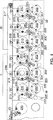
図2は、本発明の一実施形態の可変幅ロール成形装置90の外部側面図を示す。図2に示すように、ロール成形装置は、普通、Bとして示されるベースを備え、上流端がUとして、下流端がDとして定義される。ウェブ金属薄板が、連続的に、左から右へ、上流端Uから下流端Dへと通過し、その間に漸次ロール成形が行われる。
FIG. 2 shows an external side view of the variable width
ウェブのロール成形は、ローラーダイスタンドの列において漸次行われ、それらローラーダイスタンドは、普通110、111、112、113、114、115、116、117、118、119、120、121、122、123、124、125、126、及び127として示される。それらスタンドは、詳述されるように、ウェブの経路に沿い、各々独立させて間隔(intervals)を隔て、ベースBに設けられる。それらローラーダイスタンドは、5つのグループとして設けられる。スタンド110から構成されるグループIは、引き込み(lead in)又はピンチロールセクションであり、そこでは、平らなウェブが、掴まれると共に残りのロール(rolls)への経路を通るように駆動される。スタンド111、112、113、114及び115から構成されるグループIIとスタンド116、117、118、119、120、121及び122から構成されるグループIIIとは、ウェブに漸次曲げ成形を行う機能を果たす成形加工用ダイである。スタンド123、124、125、126、及び127から構成されるグループIV及びVは、仕上げ(finishing)及び矯正(straightening)処理を行う。容易に理解されるように、スタンド110−127は各々、ウェブの両側に配置されるローラーダイのペアを備える。即ち、スタンド110は、ウェブの対向する側にダイ110Aと110Bを備え、スタンド111は、ウェブの対向する側に111Aと111Bを備える、他も同様である。さらに、各スタンド(例えば110Aと110B)は、それ自身、整合するアッパー及びロアーダイから構成され、それらが各々、ウェブの上面及び下面と接触する。
Web roll forming is performed progressively in rows of roller die stands, which are typically 110, 111, 112, 113, 114, 115, 116, 117, 118, 119, 120, 121, 122, 123. , 124, 125, 126, and 127. The stands are provided on the base B along the web path and are individually spaced apart as described in detail. These roller die stands are provided as five groups. Group I, which consists of
前に論じたように、一つかそれ以上のスタンドグループI、II、III、IV及びVが、ロール成形装置90の各側部に沿う分離したサイドプレートに、設けられることが知られている。この既知の構成と対照的に、本発明によると、全ての整合するアッパー及びロアーダイが、スタンドグループI、II、III、IV及びVの各々に対し、ロール成形装置90の一方の側に、連続するサイドプレート38により設けられる。反対側の整合するアッパー及びロアーダイが、スタンドグループI、II、III、IV及びVの各々に対し、それら自身、同じような連続するサイドプレート40によって設けられる(図3に示す)。
As previously discussed, it is known that one or more stand groups I, II, III, IV and V are provided on separate side plates along each side of the
図2、3を共に参照することにより、容易に理解されるように、ロール成形装置の各側部に配置されるアッパー及びロアーダイを、異なる連続したサイドプレート38、40へ設けることで、サイドプレート38と40間を隔てる間隔(distance)が、ロール成形装置90の全長に沿い調整でき、それは、サイドプレート38とサイドプレート40の内のどちらかの移動による。図3に示すように、トランスバースパワードライブ手段(means)46が、必要に合わせ、作動することで、サイドプレート38と40が同時に又は個別に移動し、幅が変化するウェブ(webs)に適応する。そのトランスバースパワードライブ手段46は、本発明の態様から広く外れることなく、ロータリーエンコーダ又は、同種の装置などの、任意の公知である駆動機構から構成できる。
As can be easily understood by referring to FIGS. 2 and 3, the side plate is provided by providing upper and lower dies arranged on each side of the roll forming apparatus on different
従って、ロール成形装置90の運転中は、ロール成形装置90の各側部に配置された複数の異なるサイドプレートの移動とそれらの位置の調整を行う必要がなく、ロール成形装置90の製造と運転の両方が、より安価かつ、より簡素になる。このことは、本発明の重要な態様である。さらに、ロール成形装置90の各側部に単一のサイドプレート38、40を備えることにより、本発明は、著しい剛性を示し、従って、ロール成形装置90が通常の運転中に受ける反り(warping)及び曲げ(bending)応力の影響が減少する。
Therefore, during the operation of the
上に列挙したような一定の有益な利点が提供されるとはいえ、ロール成形装置90が有する単一のサイドプレート構成は、当初、ロール成形装置90により、ウェブの移動Xの軸の両側に配置される整合するダイスタンド間の一定距離の間隔が、定義されることを制限する。前に説明したように、ロール成形装置90の所定のステーション又はグループが、所定のステーション又はグループの先行又は後続するステーションと異なる距離の間隔又は幅を持つように、適応させることがしばしば必要とされる。本発明は、幾つかのコレクタープレート200を、この目的のために用いる。
Although certain beneficial advantages as listed above are provided, the single side plate configuration of
図4は、本発明の一実施の形態によるロール成形装置90の内部側面部分図であり、コレクタープレート200の用途を示している。図4に示すように、例えば、グループII及びIIIの複数のロアーダイが異なるコレクタープレート200に固定される。特許文献1内に明らかにされるように、(その参照によってその全体の内容が本願に再び、組み入れられることとする)ロアーダイ202は、スリーブ内に各々設けられ、さらにスリーブは、サイドプレート38(40)内に設けられる。スリーブの各々は、それ自身、軸受又はそれに類するものが備えられ、サイドプレート38(40)と相対的に、軸方向に移動することが可能である。コレクタープレート200は、ロアーダイ202のスリーブに、複数のボルト204又はそれに類するものにより、固定されると共に、それ自身、ジャックスクリュー206によりサイドプレート38(40)に固定される。
FIG. 4 is a partial partial side view of the
図4に示すように、ジャックスクリュー206が第1の方向に作動すると、コレクタープレート200は、サイドプレート38(40)の平面から離れる方向へ移動する。一方、ジャックスクリュー206が第2の方向に作動すると、コレクタープレート200が、サイドプレート38(40)の平面に向かう方向へ移動する。ロアーダイ202のスリーブが、コレクタープレート200の移動と協調して、直線状及び軸方向に移動することが理解される。
As shown in FIG. 4, when the
コレクタープレート200により、ロール成形装置90が、サイドプレート38とサイドプレート40の中に設けられるダイスタンド間の有効な間隔を選択的にコントロールすることが、可能となる。これは、従って、本発明の他の重要な態様である。この方法により、ウェブがロール成形装置90を通り送り込まれる際に、ロール成形装置90が、様々な幅のウェブに適応することが可能となり、その一方、ロール成形装置90全体の剛性は、依然として維持される。
The
勿論、コレクタープレート200の移動により、コレクタープレート200に固定されたロアーダイ202が、対応する軸方向への変位を行う時に、その整合するアッパーダイ210を、ずれたロアーダイ202とのアライメントを存続させるために、水平又は軸方向にシフトさせる必要がある。この目的に対し、本発明は、カムブロックと偏心アームの配置を用いる。それは、図1と共に述べられたものと同様である。
Of course, when the
図4のアッパーマッチング(整合)ダイ210の各々は、偏心軸受スリーブ内に収容されたアッパーシャフトにより支持され、スライド可能(slidably)かつ回転可能にサイドプレートに設けられる。スリーブには、スリーブの中心軸からずれたシャフト開口部が定義され、従って、アッパースリーブが回転することで、アッパーダイが、ロアーダイ202から離れ或いはロアーダイ202に向かい、垂直方向に対応する変位を行う。
Each of the upper matching dies 210 of FIG. 4 is supported by an upper shaft housed in an eccentric bearing sleeve and is slidably and rotatably mounted on the side plate. The sleeve defines a shaft opening that is offset from the central axis of the sleeve, and therefore, when the upper sleeve rotates, the upper die moves away from the
本発明も、図1に示した配置と同様に、アッパースリーブに固定されると共に、ドローバー217と関連するドローピン219間の相互作用によりコントロールされる偏心アーム215を、アッパースリーブの所望の回転を生み出すために用いるが、本発明は、複数の調整ブロック220を、サイドプレート38(40)ではなく、ボルト222により、コレクタープレート200に選択的に設ける。そのような構成とともに、ジャックスクリュー206が作動することで、コレクタープレート200がシフトし、ブロック220は、それ自身、サイドプレート38(40)から離れ或いはサイドプレート38(40)に向かい移動する。ブロック220内に形成された一般に(generally)斜めのスロットと、アーム215に固定されたカムローラー225とが相互作用することで、その結果、アッパーダイ210が、対応する水平又は軸方向への移動を行う。
The present invention also provides an
従って、本発明の他の重要な態様は、コレクタープレート200の移動が、選択された幾つかのロアーダイ202を、水平又は軸方向にシフトさせるように作用するだけでなく、整合するアッパーダイ210の対等な変位をも引き起こすということである。この方法によると、本発明は、アッパーダイ210及びロアーダイ202が、コレクタープレート200による移動にかかわらず、互いに適切な重ね合わせ(registration)のままにあることを、確実にする。さらに、本発明のロール成形装置90は、ウェブの異なるゲージを補正するために、ドローバー217を用いることで、各々210、202であるアッパー及びロアーダイ間の垂直方向の変位を調整できる能力を、維持する。
Accordingly, another important aspect of the present invention is that the movement of the
図4は、各コレクタープレート200により連結される三つのロアーダイ202を示すが、本発明はこの点に関して限定されず、本発明の態様から広く外れることなく、一つ又はより多くのロアーダイ202を、ジャックスクリュー206の作動による軸方向の移動のために、コレクタープレート200に選択的に固定してもよい。それは、コレクタープレート200のこのフレキシブルな特徴であり、従って、ロール成形装置90の長手方向に沿った特定の位置におけるコレクタープレート200の選択的な実装は、本発明の他の重要な態様である。図4に示すように、コレクタープレート200は、グループII及びIIIの選択されたロアーダイ202を結合するものとして示されるが、本発明は、アッパーダイ230とともに、容易に統合され、選択的に点在され得る。それらのアッパーダイ230は、コレクタープレート200に固定されず、図1に示すようにブロックと偏心アームの構造を保持する。
Although FIG. 4 shows three lower dies 202 connected by each
図3に戻り、コレクタープレート200の選択的な実装を示す。図3に示すように、ロール成形装置90の運転上の幅は、モータ及びエンコーダ装置300によりコントロールされるジャックスクリュー206の作動により、選択的に調整される。図3は、所定のダイスタンドの各側部の別々のモータ及びエンコーダ装置300を示すが、本発明は、この点において限定されず、本発明の態様から広く外れることなく、ダイスタンドの各側部のコレクタープレート200の水平移動をコントロールするために、ギア列に連結された共通のモータ及びエンコーダ装置を、代わりに用いるようにしてもよい。
Returning to FIG. 3, a selective implementation of the
図5は、ロール成形装置90の、各々が210及び202である、アッパー及びロアーの整合するダイのペアの部分断面図を示す。図5に図示されるように、ロール成形装置90の他の構成要素と同様にコレクタープレート200の整列(orientation)が示される。
FIG. 5 shows a partial cross-sectional view of a pair of upper and lower matching dies of
本文中に含まれる図2−5とそれらに関連する説明を考慮すると、本発明の可変幅ロール成形装置90は、ロール成形装置90に、従来、未公知である一連の寸法に関する調整を提供できることが容易に理解される。その調整とは、単一のサイドプレート38と40の選択的な移動によりコントロールされる著しい幅の調整、特定のコレクタープレート200を包含しかつ作動させることによる、ロール成形装置90に沿って方向付けられ、予め決定されたステーション又はダイスタンド(stand(s))のグループに対する選択的な幅の調整(その一方で、アッパー及びロアーダイ間の適切なアライメントが維持されると共に、それらがコレクタープレート200により軸方向にシフトする)、異なるゲージを有するウェブに適応するための、ドローバー217と偏心アーム215の配置による、全てのアッパー及びロアーの整合するダイ間の隙間の調整などである。
In view of FIGS. 2-5 included in the text and the description related thereto, the variable width
さらに、前に記述したように、本発明は、単一のサイドプレート構造を用いることにより、高い剛性と安定性を得る。それによって、ロール成形装置90の運転上の故障が減少し、同様に、より優れた構造上の完全な状態を確保する。即ち、成形されるウェブのゆがみ(warping)又はそり(bowing)が減少する。単一のサイドプレート構造を使用することに起因する追加的で有益な利点は、多くの部品と、それに関連するコストの削減であり、それらは、製造と、保全と、複数の個々に移動可能なユニットを有し、そのユニットの各々が、それら自身の対向するサイドプレートのセットを備えるロール成形装置の統合的なアライメントとに固有のものである。従って、本発明により、明らかにされた可変幅ロール成形装置を、より小さくかつよりコンパクトに設計することが可能になる。
Furthermore, as previously described, the present invention achieves high rigidity and stability by using a single side plate structure. Thereby, operational failures of the
本発明は、好適な実施の形態に関連して説明がなされたが、本発明の必須の範囲から広く外れることなく、様々な明白な変更をなし得ることと、それについて、その要素(elements)の代わりに同等物(equivalents)を用い得ることとが、当業者により理解されるであろう。従って、本発明は、明らかにされた特定の実施形態に限定されず、添付された請求の範囲に入る全ての実施形態を含むことが意図される。 Although the present invention has been described in connection with a preferred embodiment, various obvious modifications can be made without departing from the essential scope of the invention and its elements. It will be appreciated by those skilled in the art that equivalents can be used instead of. Accordingly, the present invention is not intended to be limited to the particular embodiments disclosed, but is intended to include all embodiments that fall within the scope of the appended claims.
38 第1サイドプレート
40 第2サイドプレート
200 コレクタープレート
206 ジャックスクリュー(調整装置)
300 モータ及びエンコーダ装置
38
206 Jack screw (adjuster)
300 Motor and encoder device
Claims (17)
コレクタープレートを、上記第1ダイ組立品と上記第2ダイ組立品との内の一つに固定するステップと、
上記コレクタープレートを駆動機構を介して上記サイドプレートに作動可能に結合するステップと、
上記駆動機構を、選択的に作動させることで、上記コレクタープレートを上記サイドプレートに対し直交方向へ移動させ、上記駆動機構が、上記第1ダイ組立品と上記第2ダイ組立品とを回転させることなく上記コレクタープレートが移動するよう作動するステップと、
上記コレクタープレートの上記移動とともに、上記第1ダイ組立品と第2ダイ組立品との内、上記コレクタープレートに固定されない一方を、他方に重なり合うように移動させるステップとから成ることを特徴とするロール成形装置のローラーダイ組立品の軸方向変位調整方法。 A method for adjusting the axial displacement of a roller die assembly of a roll forming device relative to a side plate provided with the roller die assembly, wherein the roller die assembly is between them A first die assembly and a second die assembly configured to receive a web;
Securing a collector plate to one of the first die assembly and the second die assembly;
Operatively coupling the collector plate to the side plate via a drive mechanism;
By selectively operating the drive mechanism , the collector plate is moved in a direction orthogonal to the side plate, and the drive mechanism rotates the first die assembly and the second die assembly. A step of moving the collector plate without movement;
Together with the movement of the collector plates, of the said first die assembly and the second die assembly, roll, characterized in that it consists either not fixed to said collector plate, the step of moving so as to overlap the other Method for adjusting axial displacement of roller die assembly of molding apparatus.
上記駆動機構を、モータ及びエンコーダ装置によりコントロールするステップを備えた請求項1記載のローラーダイ組立品の軸方向変位調整方法。 Selectively actuating the drive mechanism,
2. The method for adjusting an axial displacement of a roller die assembly according to claim 1, further comprising a step of controlling the drive mechanism by a motor and an encoder device.
上記コレクタープレートを、上記ローラダイ組立品の、第3ダイ組立品と第4ダイ組立品との内の一つに固定し、上記第3ダイ組立品と上記第4ダイ組立品とが、その間にウェブを受けるように構成するステップを備えた請求項1記載のローラーダイ組立品の軸方向変位調整方法。 Securing the collector plate to one of the first die assembly and the second die assembly;
The collector plate is fixed to one of the third die assembly and the fourth die assembly of the roller die assembly, and the third die assembly and the fourth die assembly are interposed therebetween. The method of adjusting an axial displacement of a roller die assembly according to claim 1, further comprising a step of receiving the web.
上記コレクタープレートの上記移動とともに、上記第3ダイ組立品と上記第4ダイ組立品との内、上記コレクタープレートに固定されない一方を、他方に重なり合うように移動させるステップを備えた請求項3記載のローラーダイ組立品の軸方向変位調整方法。 Along with the movement of the collector plate, the step of moving one of the first die assembly and the second die assembly that is not fixed to the collector plate so as to overlap the other,
Together with the movement of the upper Symbol collector plate, of the said third die assembly and said fourth die assembly, one that is not fixed to the collector plates, according to claim 3, further comprising the step of moving so as to overlap the other For adjusting the axial displacement of a roller die assembly.
コレクタープレートを、上記アッパーダイ組立品と上記ロアーダイ組立品との内の一つに固定するステップと、
上記コレクタープレートを駆動機構を介し上記サイドプレートに作動可能に結合するステップと、
上記駆動機構を、選択的に作動させることで、上記コレクタープレートを上記サイドプレートに対し直交方向へ移動させ、上記駆動機構が、上記アッパーダイ組立品と上記ロアーダイ組立品とを回転させることなく上記コレクタープレートが移動するよう作動するステップと、
さらに、上記コレクタープレートの上記移動とともに、上記アッパーダイ組立品と上記ロアーダイ組立品との内、上記コレクタープレートに固定されない一方を、他方に重なり合うように移動させるステップとから成ることを特徴とするロール成形装置の少なくとも二つのローラーダイ組立品の軸方向変位調整方法。 A method for adjusting the axial displacement of at least two roller die assemblies of a roll forming apparatus relative to a side plate provided with the roller die assemblies, each of the roller die assemblies being An upper die assembly and a lower die assembly configured to receive a web therebetween,
Securing a collector plate to one of the upper die assembly and the lower die assembly;
Operatively coupling the collector plate to the side plate via a drive mechanism;
By selectively operating the drive mechanism , the collector plate is moved in a direction orthogonal to the side plate, and the drive mechanism is rotated without rotating the upper die assembly and the lower die assembly. A step of operating the collector plate to move;
Furthermore, along with the movement of the collector plates, of the above-mentioned upper die assembly and said Roadai assembly, roll, characterized in that comprising a step of moving to one that is not fixed to the collector plates, overlapping the other A method for adjusting an axial displacement of at least two roller die assemblies of a forming apparatus.
上記駆動機構をモータ及びエンコーダ装置によりコントロールするステップを備えた請求項5記載のローラーダイ組立品の軸方向変位調整方法。 Selectively actuating the drive mechanism comprises:
6. The method of adjusting an axial displacement of a roller die assembly according to claim 5, further comprising a step of controlling the drive mechanism by a motor and an encoder device.
上記アッパーダイ組立品と上記ロアーダイ組立品との内、上記コレクタープレートに固定されない一つが、偏心軸受スリーブを備えるように形成するステップを設けた請求項5記載の少なくとも二つのローラーダイ組立品の軸方向変位調整方法。 Between the step of securing the collector plate to one of the upper die assembly and the lower die assembly and the step of operably coupling the collector plate to the side plate via a drive mechanism. ,
6. The shaft of at least two roller die assemblies according to claim 5, wherein one of said upper die assembly and said lower die assembly, not fixed to said collector plate, is provided with an eccentric bearing sleeve. Direction displacement adjustment method.
上記ロール成形装置の略全長に延びる第1サイドプレートと、
上記ロール成形装置の略全長に延びる第2サイドプレートとを備え、上記第1サイドプレートと、上記第2サイドプレートとが、互いに実質的に等距離で、上記ウェブの移動の軸の対向する側に方向付けられ、
上記第1サイドプレート及び上記第2サイドプレート内に形成されたアパーチャ内に配置される複数のローラーダイ組立品を備え、上記ローラーダイ組立品が、各々アッパーダイ組立品とロアーダイ組立品とを備え、
上記第1サイドプレート及び上記第2サイドプレート内の、ローラーダイ組立品間に予め決定される分離幅を選択的に変更するための調整装置を備え、上記調整装置は、上記第1サイドプレートと上記第2サイドプレートとの内の一つに配置された、上記アッパーダイ組立品と上記ロアーダイ組立品との内の一つに、固定されたコレクタープレートを備え、上記ロール成形装置により、上記第1サイドプレート及び上記第2サイドプレート内に配置されるローラーダイ組立品間の少なくとも二つの異なる幅が定義され、その一方、上記第1サイドプレート及び上記第2サイドプレート間の上記実質的に等距離な間隔が維持され、
さらに、上記調整装置の作動により、上記コレクタープレートが、上記第1サイドプレートと上記第2サイドプレートとの内の上記一つに対し実質的に直交方向へ移動するように構成されたことを特徴とする可変幅ロール成形装置。 A variable width roll forming device that performs progressive forming by directing web material through it,
A first side plate extending substantially the entire length of the roll forming device;
A second side plate extending substantially the entire length of the roll forming device, wherein the first side plate and the second side plate are substantially equidistant from each other and are opposed to each other on the axis of movement of the web Oriented to
A plurality of roller die assemblies disposed in apertures formed in the first side plate and the second side plate, wherein each of the roller die assemblies includes an upper die assembly and a lower die assembly; ,
An adjustment device for selectively changing a predetermined separation width between roller die assemblies in the first side plate and the second side plate is provided, and the adjustment device includes the first side plate and the first side plate. above disposed in one of the second side plate, to one of the above upper die assembly and said Roadai assembly, comprising a fixed collector plate, by the roll forming device, the At least two different widths between the roller die assemblies disposed in the first side plate and the second side plate are defined, while the substantially between the first side plate and the second side plate is substantially Equidistant spacing is maintained,
Furthermore, the collector plate is configured to move in a substantially orthogonal direction with respect to the one of the first side plate and the second side plate by the operation of the adjusting device. Variable width roll forming device.
上記調整装置は、上記第1サイドプレートと上記第2サイドプレートとの内の一つに配置された二つのローラーダイ組立品の、アッパーダイ組立品とロアーダイ組立品との内の一つに固定されたコレクタープレートを備え、
さらに、上記調整装置の作動により、上記コレクタープレートが、上記第1サイドプレートと上記第2サイドプレートとの内の上記一つに対し実質的に直交方向へ移動するように構成された請求項8記載の可変幅ロール成形装置。 The roller die assembly includes an upper die assembly and a lower die assembly,
The adjusting device is fixed to one of the upper die assembly and the lower die assembly of two roller die assemblies arranged in one of the first side plate and the second side plate. Collector plate,
Further, the collector plate is configured to move in a substantially orthogonal direction with respect to the one of the first side plate and the second side plate by the operation of the adjusting device. The variable width roll forming apparatus as described.
上記調整装置は、上記第1サイドプレートに配置された二つのローラーダイ組立品の、アッパーダイ組立品とロアーダイ組立品との内の一つに固定された第1コレクタープレートと、上記第2サイドプレートに配置された二つのローラーダイ組立品の、アッパーダイ組立品とロアーダイ組立品とに固定された第2コレクタープレートを備えた請求項8記載の可変幅ロール成形装置。 The roller die assembly includes an upper die assembly and a lower die assembly,
The adjusting device includes: a first collector plate fixed to one of an upper die assembly and a lower die assembly of two roller die assemblies arranged on the first side plate; and the second side plate. 9. The variable width roll forming apparatus of claim 8, comprising a second collector plate fixed to the upper die assembly and the lower die assembly of two roller die assemblies disposed on the plate.
上記アッパーダイ組立品と上記ロアーダイ組立品との内、上記コレクタープレートに固定されない一つへ、作動するように固定される第1カムローラーとを備え、上記カムローラーが、上記カムブロック組立品内に形成された溝内へスライド可能に受けられ、
さらに、上記調整装置の作動により、上記カムローラーが上記溝に沿い移動し、それにより、上記アッパーダイ組立品と上記ロアーダイ組立品との内、上記コレクタープレートに固定されない一つが、上記アッパーダイ組立品と上記ロアーダイ組立品との内、上記コレクタープレートに固定される上記一つと、重なり合うように移動するように構成された請求項8記載の可変幅ロール成形装置。 A cam block assembly fixed to the collector plate;
A first cam roller that is operatively fixed to one of the upper die assembly and the lower die assembly that is not fixed to the collector plate; and the cam roller is provided in the cam block assembly. Slidably received in the groove formed in the
Further, the cam roller is moved along the groove by the operation of the adjusting device, so that one of the upper die assembly and the lower die assembly that is not fixed to the collector plate is the upper die assembly. 9. The variable width roll forming apparatus according to claim 8, wherein the apparatus is configured to move so as to overlap with one of the product and the lower die assembly fixed to the collector plate.
Applications Claiming Priority (2)
| Application Number | Priority Date | Filing Date | Title |
|---|---|---|---|
| US09/918,747 US6647754B2 (en) | 2001-07-31 | 2001-07-31 | Variable width roll forming apparatus |
| PCT/US2001/024089 WO2003011492A1 (en) | 2001-07-31 | 2001-08-01 | Variable width roll forming apparatus |
Publications (3)
| Publication Number | Publication Date |
|---|---|
| JP2005504637A JP2005504637A (en) | 2005-02-17 |
| JP2005504637A5 JP2005504637A5 (en) | 2005-12-22 |
| JP3848945B2 true JP3848945B2 (en) | 2006-11-22 |
Family
ID=25440892
Family Applications (1)
| Application Number | Title | Priority Date | Filing Date |
|---|---|---|---|
| JP2003516715A Expired - Lifetime JP3848945B2 (en) | 2001-07-31 | 2001-08-01 | Variable width roll forming equipment |
Country Status (9)
| Country | Link |
|---|---|
| US (1) | US6647754B2 (en) |
| EP (1) | EP1412106B1 (en) |
| JP (1) | JP3848945B2 (en) |
| CN (1) | CN1273235C (en) |
| CA (1) | CA2451596C (en) |
| DE (1) | DE60136105D1 (en) |
| ES (1) | ES2313973T3 (en) |
| MX (1) | MXPA04000894A (en) |
| WO (1) | WO2003011492A1 (en) |
Families Citing this family (9)
| Publication number | Priority date | Publication date | Assignee | Title |
|---|---|---|---|---|
| WO2011002502A1 (en) | 2009-06-29 | 2011-01-06 | Mestek Machinery, Inc. | Continuously smoothly adjustable and self-aligning variable width roll forming apparatus |
| CN102319776B (en) * | 2011-08-19 | 2013-05-01 | 二十三冶建设集团有限公司 | Processing device and processing method for end plate structure of electrolytic cell casing |
| CN103551431A (en) * | 2013-11-08 | 2014-02-05 | 北方工业大学 | Variable-width roll bending forming feeding method and device thereof |
| CN104858268B (en) * | 2014-02-24 | 2016-08-31 | 北方工业大学 | A kind of cover half action roller variable-section roll-bending forming machine |
| US10364185B2 (en) | 2017-04-03 | 2019-07-30 | Michael John Mabey | Light-weight, fire-resistant composition and assembly |
| KR102512719B1 (en) | 2017-11-07 | 2023-03-23 | 삼성디스플레이 주식회사 | Condensed-cyclic compound and organic light emitting device comprising the same |
| CN108405673B (en) * | 2018-02-28 | 2019-05-17 | 重庆荣爵摩托车有限公司 | Motorcycle production line |
| US11325172B2 (en) * | 2018-08-14 | 2022-05-10 | Tefab, Inc. | Auto gauge system and method for roll forming machine |
| CN116900191B (en) * | 2023-09-13 | 2023-12-05 | 江苏誉立化工装备制造有限公司 | Tank body forming equipment of reaction kettle |
Family Cites Families (19)
| Publication number | Priority date | Publication date | Assignee | Title |
|---|---|---|---|---|
| US1125984A (en) * | 1913-07-30 | 1915-01-26 | Vellave De La Nouvelle Persienne Entole A Nervures J D Sa | Machine for corrugating venetian-blind stock. |
| US1924333A (en) * | 1932-01-06 | 1933-08-29 | United Eng Foundry Co | Roll mounting |
| BE462766A (en) * | 1945-02-05 | |||
| US3348403A (en) | 1964-11-02 | 1967-10-24 | Mckay Machine Co | Roll pass for tubing or the like |
| US3595056A (en) | 1969-07-11 | 1971-07-27 | Armco Steel Corp | Machine for roll forming sections from sheet material |
| US3914971A (en) * | 1973-04-30 | 1975-10-28 | Dan L Colbath | Die-stand for roll-forming machine |
| US3886779A (en) * | 1974-04-17 | 1975-06-03 | Engel Ind Inc | Machine for roll forming variable width profiles |
| IT1035296B (en) * | 1974-05-28 | 1979-10-20 | Colbath Dan Louis | ROLLER FORMING MACHINE TO PRODUCE ARTICLES WITH CROSS SECTIONS OF VARIABLE CONFIGURATIONS |
| JPS5927723A (en) * | 1982-08-07 | 1984-02-14 | Shiraki Kinzoku Kogyo Kk | Roll forming device |
| US4471641A (en) * | 1982-11-15 | 1984-09-18 | Mitchell James L | Method and means of continuously punching, shearing and forming sheet material |
| US4716754A (en) * | 1986-04-21 | 1988-01-05 | Collier Metal Specialties, Inc. | Roll forming machine |
| JPS6448611A (en) * | 1987-08-18 | 1989-02-23 | Nippon Kokan Kk | Chockless rolling mill |
| US5163311A (en) * | 1991-02-04 | 1992-11-17 | Engel Industries, Inc. | Rollformer for variable width edge profiles |
| US5148694A (en) * | 1991-04-26 | 1992-09-22 | Zimmerman Metals, Inc. | Sheet metal forming apparatus |
| US5319952A (en) | 1992-02-21 | 1994-06-14 | Arletti Limited | Roll forming machine |
| CA2184499A1 (en) * | 1994-04-20 | 1995-11-02 | Gary A. Knudson | Half-round gutter making apparatus |
| US5644942A (en) | 1994-10-14 | 1997-07-08 | The Bradbury Company, Inc. | Roll stand raft assembly |
| AU720605B2 (en) * | 1995-07-27 | 2000-06-08 | Formtek Inc. | Roll forming apparatus and method |
| US5787748A (en) * | 1996-09-30 | 1998-08-04 | Knudson; Gary A. | Variable panel forming apparatus and method |
-
2001
- 2001-07-31 US US09/918,747 patent/US6647754B2/en not_active Expired - Lifetime
- 2001-08-01 MX MXPA04000894A patent/MXPA04000894A/en active IP Right Grant
- 2001-08-01 EP EP01957368A patent/EP1412106B1/en not_active Expired - Lifetime
- 2001-08-01 JP JP2003516715A patent/JP3848945B2/en not_active Expired - Lifetime
- 2001-08-01 CA CA002451596A patent/CA2451596C/en not_active Expired - Lifetime
- 2001-08-01 DE DE60136105T patent/DE60136105D1/en not_active Expired - Lifetime
- 2001-08-01 CN CN01823483.6A patent/CN1273235C/en not_active Expired - Lifetime
- 2001-08-01 WO PCT/US2001/024089 patent/WO2003011492A1/en active Application Filing
- 2001-08-01 ES ES01957368T patent/ES2313973T3/en not_active Expired - Lifetime
Also Published As
| Publication number | Publication date |
|---|---|
| EP1412106A1 (en) | 2004-04-28 |
| US6647754B2 (en) | 2003-11-18 |
| ES2313973T3 (en) | 2009-03-16 |
| CN1273235C (en) | 2006-09-06 |
| CA2451596C (en) | 2007-06-19 |
| DE60136105D1 (en) | 2008-11-20 |
| US20030024290A1 (en) | 2003-02-06 |
| MXPA04000894A (en) | 2004-11-22 |
| EP1412106B1 (en) | 2008-10-08 |
| JP2005504637A (en) | 2005-02-17 |
| WO2003011492A1 (en) | 2003-02-13 |
| CN1543381A (en) | 2004-11-03 |
| CA2451596A1 (en) | 2003-02-13 |
| EP1412106A4 (en) | 2006-08-02 |
Similar Documents
| Publication | Publication Date | Title |
|---|---|---|
| JP4052394B2 (en) | Roll forming apparatus and method | |
| JP3848945B2 (en) | Variable width roll forming equipment | |
| US20150150267A1 (en) | Apparatus for forming a flat-rolled continuously conveyed dough sheet | |
| US6604397B2 (en) | Rollforming machine | |
| US6644086B1 (en) | Retro-fit roll forming mill with jack screw | |
| JP2005504637A5 (en) | ||
| EP2448694B1 (en) | Continuously smoothly adjustable and self-aligning variable width roll forming apparatus | |
| JPH09136758A (en) | Adjusting mechanism of crosswise prick punch machine | |
| JPH0532128B2 (en) | ||
| US7647803B2 (en) | Rotary apparatus with multiple guides and method of forming | |
| US3420082A (en) | Leveler | |
| JPH0734937B2 (en) | Cold roll forming equipment | |
| US20240017317A1 (en) | Drawing unit and corresponding method for metal products | |
| CA2643248A1 (en) | Multi function metal forming apparatus and method | |
| KR200230715Y1 (en) | The apparatus for semi-linear forming of a mid diameter steel pipes and tubes. | |
| AU600811B2 (en) | Material working machine | |
| CA2322669C (en) | Retro-fit rolling mill with jack screw | |
| JPH0569390A (en) | Rotary drum type cutting device | |
| US651053A (en) | Apparatus for bending sheet metal. | |
| JPH0517140B2 (en) | ||
| JPH04371320A (en) | Shape steel straightening roller machine | |
| JPH0347923B2 (en) | ||
| JP2008183611A (en) | Eccentric link-type rolling machine guide apparatus | |
| JP2003136121A (en) | Side guide of strip steel rolling mill having a pair of horizontal rolls in up and down direction with a plurality of holed pattern | |
| JPH0280113A (en) | Guide for rolling flanged shape |
Legal Events
| Date | Code | Title | Description |
|---|---|---|---|
| A529 | Written submission of copy of amendment under article 34 pct |
Free format text: JAPANESE INTERMEDIATE CODE: A529 Effective date: 20040129 |
|
| A521 | Request for written amendment filed |
Free format text: JAPANESE INTERMEDIATE CODE: A523 Effective date: 20041102 |
|
| A621 | Written request for application examination |
Free format text: JAPANESE INTERMEDIATE CODE: A621 Effective date: 20040129 |
|
| A072 | Dismissal of procedure [no reply to invitation to correct request for examination] |
Free format text: JAPANESE INTERMEDIATE CODE: A072 Effective date: 20050118 |
|
| A977 | Report on retrieval |
Free format text: JAPANESE INTERMEDIATE CODE: A971007 Effective date: 20060117 |
|
| A131 | Notification of reasons for refusal |
Free format text: JAPANESE INTERMEDIATE CODE: A131 Effective date: 20060124 |
|
| A601 | Written request for extension of time |
Free format text: JAPANESE INTERMEDIATE CODE: A601 Effective date: 20060424 |
|
| A602 | Written permission of extension of time |
Free format text: JAPANESE INTERMEDIATE CODE: A602 Effective date: 20060501 |
|
| A521 | Request for written amendment filed |
Free format text: JAPANESE INTERMEDIATE CODE: A523 Effective date: 20060621 |
|
| TRDD | Decision of grant or rejection written | ||
| A01 | Written decision to grant a patent or to grant a registration (utility model) |
Free format text: JAPANESE INTERMEDIATE CODE: A01 Effective date: 20060808 |
|
| A61 | First payment of annual fees (during grant procedure) |
Free format text: JAPANESE INTERMEDIATE CODE: A61 Effective date: 20060828 |
|
| R150 | Certificate of patent or registration of utility model |
Free format text: JAPANESE INTERMEDIATE CODE: R150 Ref document number: 3848945 Country of ref document: JP Free format text: JAPANESE INTERMEDIATE CODE: R150 |
|
| FPAY | Renewal fee payment (event date is renewal date of database) |
Free format text: PAYMENT UNTIL: 20090901 Year of fee payment: 3 |
|
| FPAY | Renewal fee payment (event date is renewal date of database) |
Free format text: PAYMENT UNTIL: 20100901 Year of fee payment: 4 |
|
| R250 | Receipt of annual fees |
Free format text: JAPANESE INTERMEDIATE CODE: R250 |
|
| FPAY | Renewal fee payment (event date is renewal date of database) |
Free format text: PAYMENT UNTIL: 20110901 Year of fee payment: 5 |
|
| R250 | Receipt of annual fees |
Free format text: JAPANESE INTERMEDIATE CODE: R250 |
|
| FPAY | Renewal fee payment (event date is renewal date of database) |
Free format text: PAYMENT UNTIL: 20120901 Year of fee payment: 6 |
|
| R250 | Receipt of annual fees |
Free format text: JAPANESE INTERMEDIATE CODE: R250 |
|
| FPAY | Renewal fee payment (event date is renewal date of database) |
Free format text: PAYMENT UNTIL: 20120901 Year of fee payment: 6 |
|
| FPAY | Renewal fee payment (event date is renewal date of database) |
Free format text: PAYMENT UNTIL: 20130901 Year of fee payment: 7 |
|
| R250 | Receipt of annual fees |
Free format text: JAPANESE INTERMEDIATE CODE: R250 |
|
| R250 | Receipt of annual fees |
Free format text: JAPANESE INTERMEDIATE CODE: R250 |
|
| R250 | Receipt of annual fees |
Free format text: JAPANESE INTERMEDIATE CODE: R250 |
|
| R250 | Receipt of annual fees |
Free format text: JAPANESE INTERMEDIATE CODE: R250 |
|
| R250 | Receipt of annual fees |
Free format text: JAPANESE INTERMEDIATE CODE: R250 |
|
| R250 | Receipt of annual fees |
Free format text: JAPANESE INTERMEDIATE CODE: R250 |
|
| R250 | Receipt of annual fees |
Free format text: JAPANESE INTERMEDIATE CODE: R250 |
|
| R250 | Receipt of annual fees |
Free format text: JAPANESE INTERMEDIATE CODE: R250 |
|
| R250 | Receipt of annual fees |
Free format text: JAPANESE INTERMEDIATE CODE: R250 |
|
| EXPY | Cancellation because of completion of term |