JP3848362B2 - Liquid dispenser for dispensing foam - Google Patents
Liquid dispenser for dispensing foam Download PDFInfo
- Publication number
- JP3848362B2 JP3848362B2 JP52532095A JP52532095A JP3848362B2 JP 3848362 B2 JP3848362 B2 JP 3848362B2 JP 52532095 A JP52532095 A JP 52532095A JP 52532095 A JP52532095 A JP 52532095A JP 3848362 B2 JP3848362 B2 JP 3848362B2
- Authority
- JP
- Japan
- Prior art keywords
- liquid
- fluid
- air
- chamber
- fluid chamber
- Prior art date
- Legal status (The legal status is an assumption and is not a legal conclusion. Google has not performed a legal analysis and makes no representation as to the accuracy of the status listed.)
- Expired - Lifetime
Links
Images


Classifications
-
- B—PERFORMING OPERATIONS; TRANSPORTING
- B05—SPRAYING OR ATOMISING IN GENERAL; APPLYING FLUENT MATERIALS TO SURFACES, IN GENERAL
- B05B—SPRAYING APPARATUS; ATOMISING APPARATUS; NOZZLES
- B05B7/00—Spraying apparatus for discharge of liquids or other fluent materials from two or more sources, e.g. of liquid and air, of powder and gas
- B05B7/0018—Spraying apparatus for discharge of liquids or other fluent materials from two or more sources, e.g. of liquid and air, of powder and gas with devices for making foam
- B05B7/0025—Spraying apparatus for discharge of liquids or other fluent materials from two or more sources, e.g. of liquid and air, of powder and gas with devices for making foam with a compressed gas supply
-
- A—HUMAN NECESSITIES
- A47—FURNITURE; DOMESTIC ARTICLES OR APPLIANCES; COFFEE MILLS; SPICE MILLS; SUCTION CLEANERS IN GENERAL
- A47K—SANITARY EQUIPMENT NOT OTHERWISE PROVIDED FOR; TOILET ACCESSORIES
- A47K5/00—Holders or dispensers for soap, toothpaste, or the like
- A47K5/14—Foam or lather making devices
-
- B—PERFORMING OPERATIONS; TRANSPORTING
- B05—SPRAYING OR ATOMISING IN GENERAL; APPLYING FLUENT MATERIALS TO SURFACES, IN GENERAL
- B05B—SPRAYING APPARATUS; ATOMISING APPARATUS; NOZZLES
- B05B11/00—Single-unit hand-held apparatus in which flow of contents is produced by the muscular force of the operator at the moment of use
- B05B11/01—Single-unit hand-held apparatus in which flow of contents is produced by the muscular force of the operator at the moment of use characterised by the means producing the flow
- B05B11/10—Pump arrangements for transferring the contents from the container to a pump chamber by a sucking effect and forcing the contents out through the dispensing nozzle
- B05B11/1087—Combination of liquid and air pumps
-
- B—PERFORMING OPERATIONS; TRANSPORTING
- B05—SPRAYING OR ATOMISING IN GENERAL; APPLYING FLUENT MATERIALS TO SURFACES, IN GENERAL
- B05B—SPRAYING APPARATUS; ATOMISING APPARATUS; NOZZLES
- B05B11/00—Single-unit hand-held apparatus in which flow of contents is produced by the muscular force of the operator at the moment of use
- B05B11/01—Single-unit hand-held apparatus in which flow of contents is produced by the muscular force of the operator at the moment of use characterised by the means producing the flow
- B05B11/02—Membranes or pistons acting on the contents inside the container, e.g. follower pistons
- B05B11/026—Membranes separating the content remaining in the container from the atmospheric air to compensate underpressure inside the container
Abstract
Description
発明の分野
本発明は液体ディスペンサに関する。より詳細には液体を泡沫体として分与するディスペンサに関する。
発明の背景
石鹸などを分与する液体ディスペンサについてはよく知られている。例えば手洗い用の石鹸を分与するディスペンサの多くはまさに液体を分与するものである。多くの適用例において、石鹸は泡沫体の形式で分与されることが好ましい。泡沫体はそれに相当する液体よりもずっと容易に分散するし、液体よりずっと大きな表面張力を有しているので、飛び散ったり流れ去ったりする浪費がずっと少なくて済む。泡沫体は液体よりずっと大きな表面積を有しているので、泡沫生成されていない液体から得られるのと同じ洗浄力を得るのに、ずっと少ない液体で済ませることができる。
公知の従来技術である泡沫生成装置には大略2つのタイプがある。1つは米国特許第4019657号および第3709437号に記載のような、泡がエアジェットで生成されるものである。この第1のタイプのものの欠点は泡沫体の質が分与させる力の変化に伴って変化してしまう点である。
第2のタイプは米国特許第3422993号および第3985271号に記載のような、多孔質材を使って泡沫生成能を有する液体をそれにポンプで通過させ、液体にエアを混合して泡沫体を生成する方法である。
このタイプの泡沫生成器の欠点は多孔質材に液体を通過させるには相当な圧力が要求される点である。さらにこれら両タイプの泡沫体ディスペンサの欠点として、泡沫生成器がディスペンサ装置の頂部に取り付けられ、チューブが液体貯蔵容器の底部に伸びているから、液体を泡沫生成器までポンプアップして、そこから泡沫体を分与するのに相当な力が要求されるという点である。
こうした多くの従来技術の泡沫生成装置において、泡沫生成ユニットは液体を保持する容器とは別にされている。したがって液体容器が交換されるとき、作業をする者は泡沫生成ユニットを液体容器に接続し直さなければならず、不便である。したがって便利で迅速に液体容器の交換ができる泡沫体ディスペンサを提供することが望まれている。
手洗い用の液体洗剤または液体石鹸は一般に洗剤の保存寿命を長くさせるため防腐剤が使われる。また空気の存在下にある石鹸の酸化を遅らせるため添加剤として酸化防止剤が典型的に使われており、これも石鹸のコストに跳ね返っている。空気の存在下で多くの石鹸は濃縮される傾向にあり、これはまた液体を分与する力の負担を増大させている。濃縮された液体は分与路を詰まらせるおそれがある。
したがって泡沫体の形式を液体から作り出し、これを分与することができるディスペンサで、ディスペンサの液体容器から押し出されるまで液体が空気にさらされないものは有利である。
発明の概要
本発明は泡沫体を作り出して分与する装置を提供するものである。この装置は内部に液体を貯蔵する容器を備える。その他、この容器に取り付け可能なポンプもある。このポンプは流体取出口から出ていく液体がエア取出口と連絡するようにエア取出口に対して配置された流体取出口を設けてある流体室を有する。この流体室は液体取入口を容器内部と流れ連絡し液体取入弁を備えている。この液体取入弁は液体が容器から流体室へ入ることができる開口位置と閉鎖位置との間を動けるようにされている。ポンプは流体室内の液体取入弁から離れた箇所に液体取出弁も備えている。液体取出弁は閉鎖位置に向けて付勢されている。ポンプは多孔部材を備え、そこを通過する流体に乱流を引き起こすようにされ、空気および流体をエア取出口および流体室の取出口から受けるように配置されている。このポンプはエア室および流体室に圧力をかける手段を備え、それによって流体室が十分に加圧されたとき液体取入弁が閉鎖して液体取出口弁が開き、流体室の取出口から液体を強制的に送り出してエア室の取出口から送り出すのと同時にエアと混合させる。そうして得られた液体・エア混合体が多孔部材を通して強制的に送り出されるのである。
本発明の別の側面では、泡沫体を作り出し分与するディスペンサが提供される。このディスペンサは内部に液体を貯蔵する容器を備えている。このディスペンサは該容器に取り付け可能なポンプを備える。このポンプはエア取入口およびエア取出口を備えたエア室を有する。該ポンプは流体取出口から出る液体がエア取出口と連絡するようにエア取出口に対して配置された流体取出口を備えた流体室を有する。この流体室は容器内部と連通する液体取入口を備え、液体が容器から流体室へ入ることができる開口位置と閉鎖位置との間を動けるようにされた液体取入弁を備えている。ポンプは流体室内の液体取入弁から離れた箇所に液体取出弁も備えている。液体取出弁は閉鎖位置に向けて付勢されている。ポンプは多孔部材を備え、そこを通過する流体に乱流を引き起こすようにされ、この多孔部材は空気および流体をエア取出口および流体室の取出口から受けるように配置されている。このポンプはエア室および流体室に圧力をかける手段を備え、それによって流体室が十分に加圧されたとき液体取入弁が閉鎖して液体取出口弁が開き、流体室の取出口から液体を強制的に送り出してエア室の取出口から送り出すのと同時にエアと混合させる。そうして得られた液体・エア混合体が多孔部材を通して強制的に送り出されるのである。このディスペンサはハウジングと、該ハウジング内に自在に挿入されるポンプが取り付けられた容器を有する。該ハウジングはハウジングに対して可動に取り付けられたテコを備える。ポンプは操作可能に該テコに組みつけられ、テコを作動することによってエアおよび流体室を同時に加圧することができるようにされている。
【図面の簡単な説明】
以下に本発明の泡沫体を分与する液体ディスペンサの実施例につき図面を参照しつつ説明する。
図1は本発明に従い構成されたディスペンサハウジングの斜視図である。
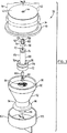
図2は液体容器およびそれに取り付けられたポンプの斜視図である。
図3は図2の泡沫生成ポンプの分解斜視図である。
図4は泡沫生成ポンプが組み立てられ、ポンプが作動していない状態における図3の4−4線で切断の断面図である。
図5は図4と同様の断面図で、ディスペンサから泡沫体を押し出している作動中の状態における断面図である。
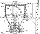
図6は図1の6−6線における断面図である。
図7は図6と同様の断面図で、ポンプが押されている状態を示す部分図である。
図8は泡沫生成ポンプを備えたディスペンサハウジングの1部分の一部切断斜視図である。
発明の詳細な説明
図1において、本発明に従い構成されたディスペンサを備える液体ディスペンサの全体が符号10で示されている。ディスペンサ10は液体ディスペンサ上部14と、後述の泡沫生成ポンプを包含するディスペンサ下部16とからなるハウジング12を有する。手操作テコないし押しボタン18がディスペンサ下部16に枢着されている。壁体のような支持面に取り付けられる背板(図示せず)に大略長方形のハウジングを係止する係止具を受けることができる小孔20がハウジング12の側面に配設されている。液体容器中の液面をみるためののぞき窓28がハウジング12の前面に設けられている。
ディスペンサ10は図2に全体を符号30で示される液体容器を内部に取り外し可能に受け止めている。該液体容器30は液体貯蔵室32および液体取出口34を備えている。この液体取出口34には泡沫生成ポンプ36が取り付けられる。液体容器30は石鹸のような液体を保持することができるフレキシブルなプラスチック容器で、折り畳み可能である。液体容器30は液体がなくなったとき容器を筋39に沿って折り畳んでI字状のセクションを形成するようにその側部38に折り畳み跡をつけてある。のぞき窓28は図1に明らかなようにハウジング12の前面に設けられ、液体容器30内の液面を見ることができるように、液体容器30をハウジング12内に組み込まれる。
図3の分解斜視図は泡沫生成ポンプ36を組み立てるのに必要な部品を示し、図4および図5は組み立てられた泡沫生成器が2通りの状態にある所を示している。泡沫生成ポンプ36は、頂部42の中央に開口部44が開口されたコップ形の部材40を有する。このコップ形部材40は、ポンプ36が液体容器30に取り付けられるとき液体容器30(一点鎖線で示されている)のスロート34縁に境を接するショルダ46が設けられている。開口部44は後述の液体貯蔵室32からポンプ36に入り込む液体のための流体取入口となる。導管48(図4、図5)がコップ形部材40内部に頂部42から連続して通路50を形成している。
泡沫生成ポンプ36は弁茎54と弁頭56を備えた取入弁52を有する。弁茎54は弁頭56から間隔をあけて伸び、間にスロット60を形成する2個のアーム58が設けられた音叉状にされている。弁頭56から離れた所にあるアーム58の端部にはショルダ62が形成されている。図4および図5に示されるように、組み立てられるときには取入弁52が開口部44中に配置され、ショルダ62と開口部44の縁端を越えて横方向に張り出す弁頭56とによって、開口部44内に保持される。
泡沫生成ポンプ36は、通路70が中に設けられているシャフト68を備えたピストン66を有する。シャフト68はその1端をピストンヘッド72に取り付けられ、他端近傍にOリング溝74を形成されている。通路70はピストンヘッド72まで伸びている。通気孔76がピストンヘッド72回りに配置されてピストンヘッド72を貫いている。ピストンヘッド72の周囲にリブ78が設けられる。
泡沫生成ポンプ36はまた、取出弁80と、連携バネ82と、針金ガーゼ、格子、ないしメッシュ84を備えている。メッシュ84はプラスチック製、針金製または布製のいずれでもよい。メッシュ84はエア・液体混合物中に乱流を起こして泡沫体生成を補助する。ピストンヘッド72中にある通路70部分にはテーパーがつけられてシャフト68内を伸びる部分より直径を大きくされていて、弁80の弁座86となる。
泡沫生成ポンプ36または、円筒形上部90と、円錐形部92と、円周リブ96が設けられた円筒形下部94と、通路98とを有する椀形部材88を備えている。円周壁102のある保護蓋ないしダストカバー100が上記通路98のカバーとして用意されている。
図4において椀形部材88の円筒形下部94内部にウエブ106が設けられ、内方に伸びてメッシュ84の支持部となっている。こうして泡沫生成ポンプ36が図3および図4に示されるように組み立てられるとき、メッシュ84がウエブ106に支持され、ピストン66が円筒形下部94中に押し込まれ、内部周縁溝79内にリブ78が嵌まって定位置にロックされる。バネ82はウエブ106に支持されているメッシュ84に対して係止され、バネ82と取出弁80は弁座86に対して弁80を押し当てて通路70中に配置される。ピストンヘッド72にはチャネル87のような流体室出口が、通気孔76近傍で通気孔76を横切るように通路70に直角に設けられる。
椀形部材88はコップ形部材40内に嵌め込まれる。円筒形上部90の直径は椀形部材88をコップ形部材40に嵌めたり出したりすることができるが十分に摩擦して椀形部材88をコップ形部材40にしっかりと嵌合することができる大きさに調整される。シャフト68は導管48内に嵌め込まれ、Oリング溝74内に嵌められるOリング110がシャフト68の外周面と導管48の内周面間をシールする。ダストカバー100(図3)がコップ形部材40内に挿入されると、円周壁102が円筒形上部90と同一直径になっているので、コップ形部材40内に嵌め込まれ摩擦嵌合してそこに保持される。
コップ形部材40の外周と液体容器30のスロート34の内周は、コップ形部材40がショルダ46に対してスロート端縁をぴったり落着かせることができるように調整されている。コップ形部材40は液体容器30に永久的に固定されるように溶接される。椀形部材88とコップ形部材40は組み合わされると流体室50ならびに液体容器30の液体貯蔵室32内部とから隔壁された空気室104を生成する。こうして泡沫体を生成するための液体と混合されるエアが液体容器30の外部から取り込まれる。コップ形部材40の内径と円筒形上部90の外径は、空気室104が椀形部材88をコップ形部材40内に押し込むことによって押圧することができるように十分にエアタイトに密封された接続となるように調整されている。
液体容器30と泡沫生成ポンプ36の組合せは次に述べるような方法で、それ単独で使用してもよいし、ディスペンサハウジング12と組合せて使用してもよい。図6は泡沫生成ポンプ36が連結された液体容器30を組み込んだハウジング12の側面断面図である。図6および図8において、ハウジング12のディスペンサ下部16は側壁120および大略長方形の開口部124が形成されている前壁122によって囲まれている。押ボタン18が側壁120の位置126に枢着され、枢軸回りに回転可能にされている。この回転運動範囲は図6および図7の押ボタン位置を比較参照することによって明確に理解される。つまり図6では押ボタン18は最大に伸び切り、図7では最大に縮まっている。
一対のアーム130が押ボタン18の内部の側縁に形成されたガイド132中をスライド動できるようにされている。これら一対のアーム130の他端は柱体138の上端に嵌合するスリーブ136中に設けられたスロット134内に受け止められる。柱体138はハウジング12に背壁142に固定されているくびき形をしたブラケット140中に設けられた穴に挿通され支持されている。このブラケット140の円形切り込みの内周縁に沿って溝144が伸びている。スリーブ136のある端部と反対側の柱体138の他端は中央切込部147と内方に突出するショルダ148とがある同じくびき形をした棚146に固定されている。柱体138各々はブラケット140と棚146間にバネ150を取り付けられてブラケット140から棚146を下方に付勢している。
押ボタン18を押すと、押ボタン18は枢軸点126回りに下方に回転し、スリーブ136内のアームの端部が上方に動いて柱体138と棚146をバネ150に抗して引き上げるように、アーム130を回転させる。押ボタン18を放すと、バネ150の動作で棚146は下方に戻る。押ボタン18が動くとアーム130がガイド132内をスライド移動する。図6および図7を参照せよ。
棚146には対向する一対の塊片160が各々ショルダ148上を内側に向けてバネ162で付勢されている。塊片160はガイド溝164内を移動する。
組み付けた液体容器30と泡沫生成ポンプ36をハウジング12内に挿入するには、キー(図示せず)を小孔20(図2)に挿通させてロック機構22(図6)に係止し、外すときは鉤24を受け金26から外してハウジング12の前面を背壁120から離して下方に回転させるようにすればよい。そうしたら図8のように液体容器30と泡沫生成ポンプ36を椀形部材88がコップ形部材40内に嵌め込まれ、リブ46が溝144に嵌め込まれるようにハウジング12内に挿入する。次に押ボタン18を押すと、棚146が持ち上げられ、塊片160の凸内面がリブ96に接触してバネ162に抗して塊片160を外方に押し付ける。棚146が十分に持ち上げられると、塊片160はリブ96の頂部を乗り越え、椀形部材88を棚146にロックする。液体容器30と泡沫生成ポンプ36がディスペンサハウジング12に組み込まれ、押ボタン18が上述のように作動されると、椀形部材88はコップ形部材40の中に押し込まれたりそこから押し出されてポンプ作動する。
作用を説明すると、液体容器30から液体を泡沫体に変えて分与するには、ユーザはハウジング12下の放出口98近くに泡沫を受けるように手を伸ばし別の手で押ボタン18を押す。図6参照。図4において、椀形部材88が下方にあるとき、液体が矢印で示したようにスロット60および開口部44経由で液体室50に流れ込むように取入弁52が開口位置におかれる。液体が液体室50およびピストン68の通路70中に充満する。取出弁80は弁座86に押し付けられて閉鎖位置におかれる。ユーザが押ボタン18を押すと椀形部材88がコップ形部材40内に押し上げられ、エア室104ならびに液体室50および通路70からなる流体室を加圧する。流体室が加圧されると、取入弁52が上方に押し上げられ、開口部44を閉鎖する。流体室がバネ82の力によって所定量だけ加圧されると、取出弁80が強制的に開放されて流体取出路87に流体を供給する。
その一定量がなくなるとエア室104が同時に加圧され、エアがピストンヘッド72の通気孔76経由で強制的に送り込まれる(矢印参照)。図5において、取出弁80が開放されると、液体が弁回りに送り込まれ、流体取出路87に導かれて直角に曲がりエア室104から強制的に送り込まれるエア流中に送り込まれる。エアと流体が混合され混合物がメッシュ84を強制的に通過させられて泡沫体を生成する。泡沫体はユーザの手まで通路98中を押し出される。泡沫体の性質、すなわちエアに対する液体比率およびエア室と流体室の相対的量はメッシュないし格子84によって制御される。エアを含む泡沫体の液体比20:1は、液体石鹸が分与されるときにきわめて有用であることが発見された。
椀形部材88がコップ形部材40からバネ150によって押し戻されると、取出口98および通気孔76経由でエア室内へ吸い込んでエアがエア室104内に吸い込まれる。メッシュ84または取出口98中に残っている泡沫体はエア室104中に吸い込まれ、泡沫生成ポンプがセルフクリーニングになる。椀形部材88はコップ形部材40から強制的に離され、取入弁52が下方に引き下げられるから開口部44を開口し液体が液体容器30から液体室50に引き込まれる。押ボタン18を押すと上述の泡沫体生成過程を繰り返す。
泡沫生成ポンプ36は従来の泡沫生成器に比し次のような利点がある。すなわち液体容器内の液体量の多少に影響されることなく等しい圧力を加えればポンプを操作して泡沫体を生成することができる。しかも液体はチューブ中を引き上げられたり、分厚い多孔物質中を強制的に通過させられる必要がないから、一般により少ない力しか必要とされない。また、液体容器の形状は従来例のものの多くがそうであるような手による絞り込みを容易にするための特定の形状に限定されていない。本発明の泡沫生成器のもう一つの利点は液体が比較的気密なディスペンサ中に、流体室から押し出されるまでエアに触れることなく維持されている点である。このため液体内容物の長期に亘る酸化を減少することができる。液体容器が交換されるたびに新しい泡沫生成ポンプが液体容器に設置される。このことは通路を詰まらせるなどの問題を避けることになるので同じポンプを長期に亘って継続使用することを回避することになり有効である。
ここに記載の泡沫生成装置のさらに別の利点は、従来装置の多くに見られる泡沫体生成のための分厚い堅牢な多孔物質の必要性が無にされていることである。薄いメッシュないし格子84で有用な品質の泡沫体を生成するのに十分なのである。
バネ82(およびおそらくは格子84)を除けば、液体容器30と泡沫生成ポンプ36はプラスチックで製造することができ、液体容器30の内容物が消費された後でも容易にリサイクルすることができる。
充満された折り畳み可能な液体容器30と、それに取付けられる泡沫生成ポンプ36(図2)の組合せは、ディスペンサ設置が要求される洗面所その他の衛生施設にディスペンサハウジング12と共に使われる交換内容のユニットとして(蓋100付きで)販売することができる。あるいは液体容器30と泡沫生成ポンプ36の組合せはユーザがこのユニットを持ち運び、該装置から泡沫体を手でポンプ操作するような適用例においても使うことができる。これは例えば患者がベッドに居ながらにして洗浄しなければならない病院などにおいて便利である。このような適用例では液体容器30を一方の手で捕まえ、椀形部材88を他方の手でポンプ操作して泡沫体を分与することになる。この場合、椀形部材88は塊片および溝の機構によってコップ形部材40と相互に嵌合して、塊片が円筒部90の外側からコップ形部材40の内面に設けられた構内に突出することになる。この溝は、椀形部材88がコップ形部材40から回転なしに引き抜かれることがないように、2回転する。 FIELD OF THE INVENTION The present invention relates to a liquid dispenser. More particularly, it relates to a dispenser that dispenses liquid as a foam.
Background of the invention Liquid dispensers for dispensing soap and the like are well known. For example, many dispensers that dispense hand-washing soaps are just liquid dispensers. In many applications it is preferred that the soap is dispensed in the form of a foam. Foams are much easier to disperse than their corresponding liquids and have a much greater surface tension than liquids, so there is much less waste of splashing and running away. Since foam has a much larger surface area than liquid, much less liquid can be used to obtain the same detergency that can be obtained from non-foamed liquid.
There are roughly two types of known prior art foam generating devices. One is that bubbles are generated by an air jet, as described in US Pat. Nos. 4,019,657 and 3,709,437. The disadvantage of this first type is that the quality of the foam changes with changes in the force it imparts.
The second type, as described in US Pat. Nos. 3,342,993 and 3,985,271, uses a porous material to pump a liquid having foam-forming ability, and mixes the liquid with air to produce a foam. It is a method to do.
A disadvantage of this type of foam generator is that considerable pressure is required to pass the liquid through the porous material. A further disadvantage of both types of foam dispensers is that the foam generator is attached to the top of the dispenser device and the tube extends to the bottom of the liquid storage container so that liquid can be pumped up to the foam generator and from there A considerable force is required to dispense the foam.
In many such prior art foam generating devices, the foam generating unit is separate from the container holding the liquid. Therefore, when the liquid container is changed, the operator must reconnect the foam generating unit to the liquid container, which is inconvenient. Accordingly, it would be desirable to provide a foam dispenser that can be conveniently and quickly replaced by a liquid container.
Liquid detergents or soaps for hand washing generally use preservatives to increase the shelf life of the detergent. Also, antioxidants are typically used as additives to delay the oxidation of soaps in the presence of air, which has also reflected the cost of the soaps. Many soaps tend to concentrate in the presence of air, which also increases the burden of the force of dispensing the liquid. Concentrated liquid can clog the dispensing path.
It is therefore advantageous to have a dispenser capable of creating and dispensing a foam form from a liquid, where the liquid is not exposed to air until it is pushed out of the liquid container of the dispenser.
SUMMARY OF THE INVENTION The present invention provides an apparatus for creating and dispensing foam. This apparatus includes a container for storing a liquid therein. Other pumps can be attached to this container. The pump has a fluid chamber provided with a fluid outlet arranged with respect to the air outlet such that liquid exiting the fluid outlet is in communication with the air outlet. The fluid chamber has a liquid intake valve in flow communication with the interior of the container. The liquid intake valve is adapted to move between an open position where liquid can enter the fluid chamber from the container and a closed position. The pump also includes a liquid take-off valve at a location away from the liquid take-in valve in the fluid chamber. The liquid removal valve is biased toward the closed position. The pump comprises a porous member, is adapted to cause turbulence in the fluid passing therethrough, and is arranged to receive air and fluid from the air outlet and the fluid chamber outlet. This pump is provided with means for applying pressure to the air chamber and the fluid chamber so that when the fluid chamber is sufficiently pressurized, the liquid intake valve is closed and the liquid outlet valve is opened, and the liquid is removed from the outlet of the fluid chamber. Is forced out and mixed with air at the same time as it is sent out from the air chamber outlet. The liquid / air mixture thus obtained is forcibly sent out through the porous member.
In another aspect of the invention, a dispenser is provided for creating and dispensing foam. This dispenser includes a container for storing a liquid therein. The dispenser includes a pump that can be attached to the container. This pump has an air chamber with an air inlet and an air outlet. The pump has a fluid chamber with a fluid outlet positioned relative to the air outlet such that liquid exiting the fluid outlet is in communication with the air outlet. The fluid chamber includes a liquid intake port that communicates with the interior of the container, and a liquid intake valve that is configured to move between an open position where liquid can enter the fluid chamber from the container and a closed position. The pump also includes a liquid take-off valve at a location away from the liquid take-in valve in the fluid chamber. The liquid removal valve is biased toward the closed position. The pump comprises a porous member and is adapted to cause turbulence in the fluid passing therethrough, the porous member being arranged to receive air and fluid from the air outlet and the fluid chamber outlet. This pump is provided with means for applying pressure to the air chamber and the fluid chamber so that when the fluid chamber is sufficiently pressurized, the liquid intake valve is closed and the liquid outlet valve is opened, and the liquid is removed from the outlet of the fluid chamber. Is forced out and mixed with air at the same time as it is sent out from the air chamber outlet. The liquid / air mixture thus obtained is forcibly sent out through the porous member. The dispenser has a housing and a container to which a pump that is freely inserted into the housing is attached. The housing includes a lever movably attached to the housing. A pump is operably assembled to the lever so that air and fluid chambers can be pressurized simultaneously by actuating the lever.
[Brief description of the drawings]
Hereinafter, embodiments of a liquid dispenser for dispensing a foam according to the present invention will be described with reference to the drawings.
FIG. 1 is a perspective view of a dispenser housing constructed in accordance with the present invention.
FIG. 2 is a perspective view of the liquid container and the pump attached thereto.
3 is an exploded perspective view of the foam generation pump of FIG.
4 is a cross-sectional view taken along line 4-4 of FIG. 3 in a state where the foam generation pump is assembled and the pump is not operating.
FIG. 5 is a cross-sectional view similar to FIG. 4 and is a cross-sectional view showing that the foam is being pushed out of the dispenser during operation.
6 is a cross-sectional view taken along line 6-6 of FIG.
FIG. 7 is a sectional view similar to FIG. 6 and is a partial view showing a state where the pump is pushed.
FIG. 8 is a partially cut perspective view of a portion of a dispenser housing with a foam generating pump.
DETAILED DESCRIPTION OF THE INVENTION In FIG. 1, an entire liquid dispenser comprising a dispenser constructed in accordance with the present invention is indicated generally at 10. The
The
The exploded perspective view of FIG. 3 shows the parts necessary to assemble the
The
The
The
A
In FIG. 4, a
The hook-shaped
The outer periphery of the cup-shaped
The combination of the
A pair of
When the
A pair of
In order to insert the assembled
In operation, to change the liquid from the
When the fixed amount disappears, the
When the bowl-shaped
The
Yet another advantage of the foam generator described herein is that the need for a thick, robust porous material for foam generation found in many of the prior devices is eliminated. A thin mesh or
With the exception of the spring 82 (and possibly the grid 84), the
The combination of a filled foldable
Claims (9)
a)内部のある折り畳み自在の液体容器と、
b)該液体容器内の液体が前記装置内において気密に維持されるように液体容器の下方に取り付けられたポンプと、
c)ハウジングと、からなり、
前記ポンプは、エア取入口とエア取出口とを有するエア室と、流体取出口から出る液体がエア取出口を横切るようにエア取出口に対して配置された流体取出口を備えた流体室とを有し、該流体室は、前記液体容器の内部に連通している流体取入口と、液体取入弁と、液体取出弁とを有し、前記液体取入弁は、流体室内の弁座に着座する弁茎を備え、流体室内の弁茎が液体容器の内部に突出して流体取入口に配置されていて、液体が前記液体容器から流体室に流入する開口位置と閉鎖位置との間を移動可能であり、前記液体取出弁は前記液体取入弁から離れた箇所の流体室内に配置されていて閉鎖位置に付勢されており、前記ポンプは、エア室のエア取出口および流体室の流体取出口からエアおよび流体を受けるように配置されて流体を中に通過させることによって流体に乱流を引き起こす多孔部材と、エア室および流体室を互いに限定し合う第1部材と第2部材とを有し、前記第1部材は、液体容器に取り付け可能であり、流体取入口と、該流体取入口から伸びる通路を限定する導管とを備え、前記第2部材は、基部と該基部から伸びるピストンとを備えていて前記導管内に受け入れられており、第1部材に対して入れ子の関係で移動させることができ、前記ピストンは導管中の通路と連通して伸びる通路を備え、導管中の通路とピストンとは相俟って前記流体室を形成しており、前記第2部材を第1部材の方に移動させることにより流体室およびエア室を加圧し、それによって液体取入弁が液体容器の内部の方に強制的に押し付けられて弁座が流体取入口を閉鎖し、流体室およびエア室から液体およびエアを送り出すようにされており、前記第2部材を第1部材から離す方向に移動させることにより流体室内を減圧し、それによって液体取入弁を開口位置に引き付け、液体容器から液体を流体室へ送り込むようにされており、流体室が十分に加圧されたときは液体取入弁が閉鎖し液体取出弁が開口して流体室の流体取出口から液体を強制的に送り出し、同時にエア室のエア取出口から送り出されたエアと混合して前記多孔部材から強制的に送り出して液体・エア混合物を生成し、
前記ハウジングはテコが可動可能に取付けられており、前記ポンプの第2部材が、テコを作動させると第2部材が第1部材に対して移動するように前記テコに操作可能に組みつけられていることを特徴とする泡沫体を生成し分与する装置。A device for producing and dispensing foam, the device comprising:
a) a foldable liquid container with an interior;
b) a pump attached below the liquid container so that the liquid in the liquid container is kept airtight in the device;
c) a housing,
The pump includes an air chamber having an air inlet and an air outlet, and a fluid chamber having a fluid outlet disposed with respect to the air outlet such that liquid exiting the fluid outlet crosses the air outlet. The fluid chamber has a fluid inlet communicating with the interior of the liquid container, a liquid inlet valve, and a liquid outlet valve, and the liquid inlet valve has a valve seat in the fluid chamber. A valve stem that sits in the fluid chamber, the valve stem in the fluid chamber protrudes into the liquid container and is disposed in the fluid intake port, and the gap between the open position and the closed position where the liquid flows from the liquid container into the fluid chamber is provided. The liquid take-off valve is disposed in a fluid chamber at a location remote from the liquid intake valve and is biased to a closed position, and the pump is provided with an air outlet of the air chamber and a fluid chamber. Arranged to receive air and fluid from the fluid outlet to allow fluid to pass through A porous member that causes turbulent flow in the fluid, and a first member and a second member that limit the air chamber and the fluid chamber to each other, the first member being attachable to a liquid container, An inlet and a conduit defining a passage extending from the fluid inlet, wherein the second member comprises a base and a piston extending from the base and is received within the conduit; The piston is provided with a passage extending in communication with a passage in the conduit, and the passage in the conduit and the piston together form the fluid chamber, The fluid member and the air chamber are pressurized by moving the second member toward the first member, whereby the liquid intake valve is forced toward the inside of the liquid container and the valve seat moves the fluid inlet. Closed, fluid chamber and Liquid and air are sent out from the chamber, and the fluid chamber is depressurized by moving the second member in a direction away from the first member, thereby attracting the liquid intake valve to the open position, and a liquid container When the fluid chamber is sufficiently pressurized, the liquid intake valve closes and the liquid extraction valve opens to force the liquid from the fluid outlet of the fluid chamber. Sending out, simultaneously mixing with the air sent out from the air outlet of the air chamber and forcibly sending out from the porous member to produce a liquid / air mixture;
The lever is movably attached to the housing , and the second member of the pump is operably assembled to the lever so that when the lever is operated, the second member moves relative to the first member. A device for producing and dispensing a foam characterized by comprising:
b)該液体容器に取付可能なポンプと、
c)ハウジングと、
からなる泡沫体を生成し分与するディスペンサであって、
前記ポンプは、エア取入口とエア取出口とが設けられたエア室と、流体取出口から出た液体がエア取出口と連絡するようにエア取出口に対して配置された流体取出口を備えた流体室とを有し、該流体室は、前記液体容器の内部に連通している流体取入口と、液体取入弁と、液体取出弁とを有し、前記液体取入弁は前記液体容器から液体が流体室に流入する開口位置と閉鎖位置との間を移動可能であり、前記液体取出弁は前記液体取入弁から離れた箇所の流体室内に配置されていて閉鎖位置に付勢されており、前記ポンプは、エア取出口と流体取出口からのエアおよび流体を受け止めるように配置されその中を通過させることによって流体中に乱流を引き起こす多孔部材と、エア室および流体室を加圧する部材を備えており、それによって流体室が十分に加圧されたときは液体取入弁が閉鎖して液体取出弁が開口し、それによって液体を流体取出口から強制的に送り出し、同時にエア取出口から送り出されてくるエアと混合して前記多孔部材中を強制的に通過させて液体・エア混合物を生成し、
前記ハウジングはテコが可動可能に取付けられており、前記ポンプが、テコを作動させるとエア室と流体室を同時に加圧するように前記テコに操作可能に組みつけられていることを特徴とするディスペンサ。a) a liquid container with an interior;
b) a pump attachable to the liquid container;
c) a housing;
A dispenser for producing and dispensing foam comprising:
The pump includes an air chamber provided with an air inlet and an air outlet, and a fluid outlet arranged with respect to the air outlet so that liquid exiting from the fluid outlet communicates with the air outlet. and a fluid chamber has, fluid chamber has a inlet fluid in communication with the interior of the liquid container, and Iriben preparative liquid, and a liquid take-out valve, the liquid collected Iriben the said liquid The liquid can be moved between an open position where the liquid flows from the container into the fluid chamber and a closed position, and the liquid take-off valve is disposed in the fluid chamber at a location away from the liquid intake valve and biased to the closed position. It is, the pump includes a porous member causing turbulence in the fluid by passing therethrough are arranged so as to receive the air and fluid from the d a outlet and a flow body outlet, the air chamber and the fluid It includes a pressurizing member the chamber, whereby the fluid It is closed is Iriben preparative liquid when sufficiently pressurized liquid extraction valve is opened, thereby feeding the liquid forcibly from the takeout fluid, mixed with air coming fed from takeout air simultaneously the porous through the member forced through by generating a liquid-air mixture Te,
The housing has a lever is mounted so as to be movable, the dispenser the pump, characterized in that it operably assembled to the lever to press simultaneously pressurizing the air chamber and the fluid chamber when actuating the lever .
Applications Claiming Priority (3)
| Application Number | Priority Date | Filing Date | Title |
|---|---|---|---|
| US223,148 | 1994-04-05 | ||
| US08/223,148 US5445288A (en) | 1994-04-05 | 1994-04-05 | Liquid dispenser for dispensing foam |
| PCT/CA1995/000175 WO1995026831A1 (en) | 1994-04-05 | 1995-04-03 | Liquid dispenser for dispensing foam |
Publications (2)
| Publication Number | Publication Date |
|---|---|
| JPH09503161A JPH09503161A (en) | 1997-03-31 |
| JP3848362B2 true JP3848362B2 (en) | 2006-11-22 |
Family
ID=22835248
Family Applications (1)
| Application Number | Title | Priority Date | Filing Date |
|---|---|---|---|
| JP52532095A Expired - Lifetime JP3848362B2 (en) | 1994-04-05 | 1995-04-03 | Liquid dispenser for dispensing foam |
Country Status (10)
| Country | Link |
|---|---|
| US (1) | US5445288A (en) |
| EP (1) | EP0703831B1 (en) |
| JP (1) | JP3848362B2 (en) |
| AT (1) | ATE174816T1 (en) |
| AU (1) | AU705591B2 (en) |
| CA (1) | CA2164341C (en) |
| DE (1) | DE69506819T2 (en) |
| DK (1) | DK0703831T3 (en) |
| ES (1) | ES2127526T3 (en) |
| WO (1) | WO1995026831A1 (en) |
Cited By (1)
| Publication number | Priority date | Publication date | Assignee | Title |
|---|---|---|---|---|
| US10898034B1 (en) | 2019-07-02 | 2021-01-26 | Armin Arminak | All plastic hand foam pump |
Families Citing this family (147)
| Publication number | Priority date | Publication date | Assignee | Title |
|---|---|---|---|---|
| EP0817587B1 (en) * | 1995-03-29 | 1999-12-22 | HAGLEITNER BETRIEBSHYGIENE GESELLSCHAFT mbH & Co. KG | Foamed soap dispenser |
| GB9526391D0 (en) * | 1995-12-22 | 1996-02-21 | Diversey Equipment Technologie | Dispenser |
| US6093574A (en) | 1997-08-11 | 2000-07-25 | Ventana Medical Systems | Method and apparatus for rinsing a microscope slide |
| US6045759A (en) * | 1997-08-11 | 2000-04-04 | Ventana Medical Systems | Fluid dispenser |
| US8137619B2 (en) * | 1997-08-11 | 2012-03-20 | Ventana Medical Systems, Inc. | Memory management method and apparatus for automated biological reaction system |
| US20020110494A1 (en) * | 2000-01-14 | 2002-08-15 | Ventana Medical Systems, Inc. | Method and apparatus for modifying pressure within a fluid dispenser |
| US20050135972A1 (en) * | 1997-08-11 | 2005-06-23 | Ventana Medical Systems, Inc. | Method and apparatus for modifying pressure within a fluid dispenser |
| US6192945B1 (en) | 1997-08-11 | 2001-02-27 | Ventana Medical Systems, Inc. | Fluid dispenser |
| US6082586A (en) * | 1998-03-30 | 2000-07-04 | Deb Ip Limited | Liquid dispenser for dispensing foam |
| US6006388A (en) * | 1998-04-14 | 1999-12-28 | Young; Cecil Blake | Dispenser for dispensing concentrated liquid soap to industrial cleaning apparatuses |
| US6142343A (en) * | 1998-12-30 | 2000-11-07 | Steris Inc | Cap and dust cover for an antiseptic soap dispenser |
| US6446840B2 (en) * | 2000-05-18 | 2002-09-10 | Ophardt Product Kg | Apparatus for making and dispensing foam |
| US6612468B2 (en) | 2000-09-15 | 2003-09-02 | Rieke Corporation | Dispenser pumps |
| CA2341659C (en) | 2001-03-20 | 2007-08-07 | Hygiene-Technik Inc. | Liquid dispenser for dispensing foam |
| NL1019348C2 (en) | 2001-11-12 | 2003-05-13 | Bentfield Europ Bv | Foam dispenser, housing and storage container therefor. |
| NL1020641C2 (en) | 2001-11-12 | 2003-05-15 | Bentfield Europ Bv | Dispenser for dispensing a liquid and housing for such a dispenser. |
| US6581804B1 (en) | 2002-01-11 | 2003-06-24 | Joseph S. Kanfer | Holder for aerosol dispenser |
| US7378058B2 (en) * | 2002-01-30 | 2008-05-27 | Ventana Medical Systems, Inc. | Method and apparatus for modifying pressure within a fluid dispenser |
| FR2836457B1 (en) * | 2002-02-26 | 2004-04-09 | Oreal | DEFORMABLE POT |
| GB0208806D0 (en) | 2002-04-17 | 2002-05-29 | Rieke Corp | Dispenser pumps |
| US6910579B2 (en) | 2002-05-28 | 2005-06-28 | Georgia-Pacific Corporation | Refillable flexible sheet dispenser |
| US6868990B2 (en) * | 2002-09-26 | 2005-03-22 | Emsar, Inc. | Fluid dispenser with shuttling mixing chamber |
| US7004356B1 (en) | 2003-07-28 | 2006-02-28 | Joseph S. Kanfer | Foam producing pump with anti-drip feature |
| US20050072805A1 (en) * | 2003-08-20 | 2005-04-07 | Matthews Shaun Kerry | Foam dispenser with rigid container |
| US7389893B2 (en) * | 2003-09-10 | 2008-06-24 | Rieke Corporation | Inverted dispensing pump |
| US7325704B2 (en) * | 2003-09-10 | 2008-02-05 | Rieke Corporation | Inverted dispensing pump with vent baffle |
| PL3428257T3 (en) | 2003-09-29 | 2023-11-20 | Deb Ip Limited | High alcohol content gel-like and foaming compositions |
| CA2464905C (en) | 2004-03-19 | 2008-12-23 | Hygiene-Technik Inc. | Dual component dispenser |
| AU2011253813B2 (en) * | 2004-05-07 | 2013-08-22 | Deb Ip Limited | A method of producing foamed cleansers with suspended particles and a dispenser for such cleansers |
| CA2566153C (en) * | 2004-05-07 | 2014-01-14 | Deb Ip Limited | Foamed cleanser with suspended particles, a method of producing same and a dispenser therefore |
| US7261268B2 (en) * | 2004-06-15 | 2007-08-28 | S.C. Johnson & Son, Inc. | Wall mountable holder for a container |
| CA2474178C (en) * | 2004-07-14 | 2010-10-12 | Hygiene-Technik Inc. | Sink side touchless foam dispenser |
| CA2477584C (en) * | 2004-08-12 | 2011-07-26 | Hygiene-Technik Inc. | Disposable dispenser |
| PL1666073T3 (en) * | 2004-10-13 | 2009-01-30 | Procter & Gamble | Device for delivering an antimicrobial composition |
| DE102004062775A1 (en) | 2004-12-21 | 2006-06-29 | Stockhausen Gmbh | Alcoholic pump foam |
| US7802701B2 (en) * | 2005-01-14 | 2010-09-28 | Rieke Corporation | Up-lock seal for dispenser pump |
| DE102005006845A1 (en) | 2005-02-14 | 2006-08-17 | Stockhausen Gmbh | donor |
| BRPI0608347A2 (en) | 2005-03-07 | 2009-12-08 | Deb Worldwide Healthcare Inc | foaming alcohol composition, foaming concentrate, foaming disinfectant alcohol composition, methods for forming, producing and dispensing a foam, unpressurized dispenser, and methods for using an alcoholic foam composition for personal disinfection and for producing and applying to an individual's skin an alcoholic composition of skin disinfectant foam |
| CA2504989C (en) * | 2005-04-22 | 2013-03-12 | Gotohti.Com Inc. | Stepped pump foam dispenser |
| CA2509295C (en) * | 2005-04-22 | 2013-11-19 | Gotohti.Com Inc. | Bellows dispenser |
| US7770874B2 (en) * | 2005-04-22 | 2010-08-10 | Gotohii.com Inc. | Foam pump with spring |
| US7337930B2 (en) * | 2005-05-20 | 2008-03-04 | Gotohti.Com Inc. | Foaming pump with improved air inlet valve |
| US8336740B1 (en) | 2005-11-02 | 2012-12-25 | Daansen Warren S | Fluid dispenser and pump adapter system therefor |
| US20070148101A1 (en) * | 2005-12-28 | 2007-06-28 | Marcia Snyder | Foamable alcoholic composition |
| EP1818109B1 (en) * | 2006-01-25 | 2010-03-17 | Technical Concepts Bentfield B.V. | Fluid product dispenser and pump with constantly open inlet valve |
| ATE428339T1 (en) * | 2006-02-07 | 2009-05-15 | Technical Concepts Bentfield B | FLUID DISPENSER |
| GB2437510A (en) * | 2006-04-26 | 2007-10-31 | Packaging Innovation Ltd | Dispenser mechanism |
| US7780039B2 (en) | 2006-04-28 | 2010-08-24 | Buckeye International, Inc. | Soap dispensing pump head with vacuum applying drip guard member |
| US7735692B2 (en) * | 2006-10-10 | 2010-06-15 | Meadwestvaco Calmar, Inc. | Rotating dispenser head with locking and venting closure connector for an air foaming pump dispenser |
| CA2569194C (en) * | 2006-11-29 | 2014-01-14 | Gotohti.Com Inc. | Arcuate to linear motion translation assembly |
| MY151923A (en) * | 2007-02-16 | 2014-07-31 | Gojo Ind Inc | Flexible impeller pumps for mixing individual components |
| GB2447422A (en) * | 2007-03-12 | 2008-09-17 | Packaging Innovation Ltd | Dispenser with resilient ported outlet valve |
| US20090057345A1 (en) * | 2007-08-31 | 2009-03-05 | Dukes Stephen A | Fluid dispenser |
| EP2195619A4 (en) * | 2007-09-13 | 2011-08-10 | Idispense Llc | System and apparatus for dispensing concentrated materials |
| EP2194828B1 (en) * | 2007-09-21 | 2011-12-14 | Packaging Innovation Limited | Dispenser mechanism |
| US8261950B2 (en) * | 2007-10-22 | 2012-09-11 | Georgia-Pacific Consumer Products Lp | Pumping dispenser |
| US8056768B2 (en) * | 2007-12-28 | 2011-11-15 | Snodgrass David L | Foam pump assembly |
| US8579159B2 (en) * | 2008-01-18 | 2013-11-12 | Gojo Industries, Inc. | Squeeze action foam pump |
| US7850049B2 (en) | 2008-01-24 | 2010-12-14 | Gojo Industries, Inc. | Foam pump with improved piston structure |
| US8020731B2 (en) * | 2008-01-30 | 2011-09-20 | Evonik Stockhausen, Llc | Dispenser |
| US8365963B2 (en) | 2008-01-30 | 2013-02-05 | Evonik Stockhausen, Llc | Fluid dispenser selectively secured to a countertop |
| US8499981B2 (en) * | 2008-02-08 | 2013-08-06 | Gojo Industries, Inc. | Bifurcated stem foam pump |
| US8313010B2 (en) * | 2008-02-08 | 2012-11-20 | Gojo Industries, Inc. | Bifurcated foam pump assembly |
| US8047403B2 (en) * | 2008-02-08 | 2011-11-01 | Gojo Industries, Inc. | Bifurcated stem foam pump |
| US8047404B2 (en) * | 2008-02-08 | 2011-11-01 | Gojo Industries, Inc. | Bifurcated stem foam pump |
| US7861895B2 (en) * | 2008-03-18 | 2011-01-04 | Gojo Industries, Inc. | High velocity foam pump |
| ATE490714T1 (en) * | 2008-05-29 | 2010-12-15 | Gojo Ind Inc | PULL POWERED FOAM PUMP |
| CA2634981C (en) * | 2008-06-12 | 2016-08-09 | Gotohti.Com Inc. | Withdrawal discharging piston pump |
| EP2135681B1 (en) * | 2008-06-20 | 2015-04-15 | Gojo Industries, Inc. | Two-stroke foam pump |
| GB0815881D0 (en) | 2008-09-01 | 2008-10-08 | Rieke Corp | Liquid dosing devices |
| US9433960B2 (en) | 2008-09-01 | 2016-09-06 | Rieke Corporation | Liquid dosing devices |
| GB0912065D0 (en) * | 2009-07-10 | 2009-08-19 | Reckitt & Colman Overseas | A fluid delivery system |
| GB2472235B (en) | 2009-07-29 | 2011-07-06 | Brightwell Dispensers Ltd | Dispensing device with a disposable pump |
| US8733591B2 (en) * | 2009-10-04 | 2014-05-27 | G.A.B. Develoment & Engineering B.V. | Fluid product dispenser with shunting chamber and governing device |
| US8308027B2 (en) | 2009-12-01 | 2012-11-13 | Regent Medical Center | Automatic soap dispenser with top-side motor and methods |
| US8418889B2 (en) * | 2010-01-11 | 2013-04-16 | Rieke Corporation | Inverted dispenser pump with liquid inlet cup valve |
| GB201000601D0 (en) | 2010-01-14 | 2010-03-03 | Rieke Corp | Pump dispensers |
| WO2011133077A1 (en) | 2010-04-22 | 2011-10-27 | Sca Hygiene Products Ab | Pump soap dispenser |
| AT509749B1 (en) * | 2010-04-23 | 2012-11-15 | Hagleitner Hans Georg | DONOR |
| US20110272432A1 (en) * | 2010-05-10 | 2011-11-10 | Baughman Gary M | Foam dispenser |
| PL2582467T3 (en) | 2010-06-15 | 2016-04-29 | Brightwell Dispensers Ltd | Foam pump |
| GB201011144D0 (en) | 2010-07-01 | 2010-08-18 | Rieke Corp | Dispensers |
| GB201011143D0 (en) | 2010-07-01 | 2010-08-18 | Rieke Corp | Dispensers |
| CA2722646C (en) * | 2010-11-26 | 2018-01-02 | Gotohti.Com Inc. | Air assisted severance of viscous fluid stream |
| US8944288B2 (en) | 2011-02-22 | 2015-02-03 | Gojo Industries, Inc. | Collapsible container |
| CN103649760B (en) | 2011-06-01 | 2015-09-09 | 文塔纳医疗系统公司 | There is the knockout of filter element |
| US9101952B2 (en) * | 2011-06-06 | 2015-08-11 | Gojo Industries, Inc. | Modular pump |
| US8651328B2 (en) | 2011-07-14 | 2014-02-18 | Georgia-Pacific Consumer Products Lp | Pumping dispenser shield |
| US8662355B2 (en) | 2011-08-11 | 2014-03-04 | Gojo Industries, Inc. | Split body pumps for foam dispensers and refill units |
| US8875952B2 (en) | 2012-03-12 | 2014-11-04 | Gojo Industries, Inc. | Air-activated sequenced valve split foam pump |
| US8814005B2 (en) * | 2012-04-27 | 2014-08-26 | Pibed Limited | Foam dispenser |
| US9340337B2 (en) | 2012-05-01 | 2016-05-17 | Ecolab Usa Inc. | Dispenser with lockable pushbutton |
| US8851331B2 (en) | 2012-05-04 | 2014-10-07 | Ecolab Usa Inc. | Fluid dispensers with adjustable dosing |
| US9611839B2 (en) | 2012-05-09 | 2017-04-04 | Gojo Industries, Inc. | Low residual inverted pumps, dispensers and refill units |
| US9045268B2 (en) | 2012-07-25 | 2015-06-02 | Gojo Industries, Inc. | Collapsible container and dispenser employing a collapsible container |
| US9204765B2 (en) | 2012-08-23 | 2015-12-08 | Gojo Industries, Inc. | Off-axis inverted foam dispensers and refill units |
| US20140054323A1 (en) | 2012-08-23 | 2014-02-27 | Gojo Industries, Inc. | Horizontal pumps, refill units and foam dispensers with integral air compressors |
| US9038862B2 (en) * | 2013-01-23 | 2015-05-26 | Gojo Industries, Inc. | Pumps with container vents |
| US9179808B2 (en) | 2012-08-30 | 2015-11-10 | Gojo Industries, Inc. | Horizontal pumps, refill units and foam dispensers |
| US9307871B2 (en) | 2012-08-30 | 2016-04-12 | Gojo Industries, Inc. | Horizontal pumps, refill units and foam dispensers |
| JP2015531726A (en) | 2012-08-31 | 2015-11-05 | アーミナック・アンド・アソシエイツ・リミテッド・ライアビリティ・カンパニー | Inverted squeeze former |
| US8955718B2 (en) | 2012-10-31 | 2015-02-17 | Gojo Industries, Inc. | Foam pumps with lost motion and adjustable output foam pumps |
| US9266134B2 (en) * | 2012-12-11 | 2016-02-23 | Gojo Industries, Inc. | Vented check valves, pumps and refill units with vented check valves |
| US9296508B2 (en) | 2012-12-13 | 2016-03-29 | Gojo Industries, Inc. | Collapsible containers and refill units |
| US8827119B2 (en) * | 2013-01-23 | 2014-09-09 | Gojo Industries, Inc. | Pull pumps, refill units and dispensers for pull pumps |
| US9254068B2 (en) * | 2013-01-25 | 2016-02-09 | Gojo Industries, Inc. | Sequenced adjustable volume pumps, refill units and dispensers |
| US8991655B2 (en) | 2013-02-15 | 2015-03-31 | Ecolab Usa Inc. | Fluid dispensers with increased mechanical advantage |
| USD742137S1 (en) | 2013-03-15 | 2015-11-03 | Buckeye International, Inc. | Dispenser for dispensing cleaning solutions |
| US8820585B1 (en) | 2013-03-15 | 2014-09-02 | Pibed Limited | Foam dispenser with a porous foaming element |
| EP2988878A1 (en) * | 2013-04-25 | 2016-03-02 | Gojo Industries, Inc. | Horizontal pumps with reduced part count, refill units and dispensers |
| WO2014201322A1 (en) * | 2013-06-14 | 2014-12-18 | Gojo Industries, Inc. | Foam cartridges, pumps, refill units and foam dispensers utilizing the same |
| ES2727340T3 (en) * | 2013-10-03 | 2019-10-15 | Zobele Holding Spa | Substance Distribution Device |
| US9648992B2 (en) * | 2013-12-19 | 2017-05-16 | Gojo Industries, Inc. | Pumps with vents to vent inverted containers and refill units having non-collapsing containers |
| CA2837774A1 (en) * | 2013-12-20 | 2015-06-20 | Heiner Ophardt | Piston pump with vacuum relief |
| JP2017505658A (en) | 2014-01-15 | 2017-02-23 | ゴジョ・インダストリーズ・インコーポレイテッド | Dispenser with pump with angle outlet, refill unit and angle outlet |
| AU2015218741B2 (en) | 2014-02-24 | 2019-07-11 | Gojo Industries, Inc. | Vented non-collapsing containers, refillable refill containers, dispensers and refill units |
| GB2524004A (en) * | 2014-03-10 | 2015-09-16 | Stratec Biomedical Ag | Dispenser |
| USD757459S1 (en) * | 2014-04-25 | 2016-05-31 | Hansgrohe Se | Soap dispenser |
| MX2016013357A (en) * | 2014-05-12 | 2017-02-09 | Deb Ip Ltd | Improved foam pump. |
| WO2015179555A1 (en) | 2014-05-20 | 2015-11-26 | Gojo Industries, Inc. | Two-part fluid delivery systems |
| CA2956212C (en) | 2014-07-30 | 2023-03-28 | Gojo Industries, Inc. | Vented refill units and dispensers having vented refill units |
| USD767301S1 (en) * | 2014-10-07 | 2016-09-27 | Daansen U.S.A. Inc. | Dispenser |
| CA159265S (en) * | 2014-11-03 | 2016-04-05 | Blp Internat Inc | Liquid dispenser |
| AU362367S (en) * | 2014-12-19 | 2015-06-18 | Sca Hygiene Prod Ab | Tissue dispenser |
| USD766008S1 (en) * | 2014-12-22 | 2016-09-13 | Richard L. Ernst | Soap and gel dispenser |
| USD784726S1 (en) | 2014-12-23 | 2017-04-25 | Buckeye International, Inc. | Dispenser for dispensing cleaning solutions |
| USD773849S1 (en) * | 2015-03-13 | 2016-12-13 | Buckeye International, Inc. | Dispenser for dispensing a cleaning solution |
| USD775852S1 (en) * | 2015-05-21 | 2017-01-10 | Gregory L. Indruk | Dispenser |
| USD795608S1 (en) | 2015-10-12 | 2017-08-29 | Buckeye International, Inc. | Dispenser for dispensing cleaning solutions, a cover piece for a dispenser for dispensing cleaning solutions, and a portion of a dispenser for dispensing cleaning solutions |
| GB2543845A (en) | 2015-11-02 | 2017-05-03 | Deb Ip Ltd | Foaming component |
| NL2015724B1 (en) | 2015-11-04 | 2017-05-24 | Gab Eng & Dev B V | Storage holder for a dispenser. |
| US9750377B2 (en) | 2015-12-17 | 2017-09-05 | Peter Bai | Foam generator |
| US10034583B2 (en) | 2016-03-04 | 2018-07-31 | Gpcp Ip Holdings Llc | Dispenser with stroke adjustment capabilities |
| NL2016644B1 (en) | 2016-04-20 | 2017-11-07 | Gab Eng & Development B V | Storage holder for a dispenser |
| US10188241B2 (en) * | 2016-05-27 | 2019-01-29 | Vi-Jon, Inc. | Dispenser assembly |
| CA2942640C (en) | 2016-09-21 | 2023-06-27 | Op-Hygiene Ip Gmbh | Pump for under counter dispensing system |
| JP6582027B2 (en) * | 2016-09-29 | 2019-09-25 | 花王株式会社 | Foam discharge container |
| EP3554329A1 (en) * | 2016-12-14 | 2019-10-23 | GOJO Industries, Inc. | Actuating mechanisms for manual dispensers |
| USD831377S1 (en) | 2017-02-03 | 2018-10-23 | Rubbermaid Commercial Products, Llc | Soap dispenser |
| US10561282B2 (en) * | 2017-12-21 | 2020-02-18 | Speakman Company | Ligature-resistant dispenser |
| AU2019243017B2 (en) * | 2018-03-28 | 2023-07-27 | Gojo Industries, Inc. | Foam pumps, refill units and dispensers with differential bore suck-back mechanism |
| JP2022509650A (en) * | 2018-12-03 | 2022-01-21 | コティ インコーポレイテッド | Fluid dispenser |
| RU190573U1 (en) * | 2018-12-14 | 2019-07-04 | Евгений Александрович Непокульчицкий | Dosing device |
| TWI766620B (en) | 2021-03-17 | 2022-06-01 | 源美股份有限公司 | Sprinkler with adjustable flow of mixed liquid and clean water |
| TWI754565B (en) | 2021-03-17 | 2022-02-01 | 源美股份有限公司 | Sprinkler for spraying mixed liquid and clean water |
| US11744413B2 (en) | 2021-10-07 | 2023-09-05 | Deb Ip Limited | Dispenser assembly |
| US11744412B2 (en) | 2021-10-07 | 2023-09-05 | Deb Ip Limited | Dispenser system |
Family Cites Families (17)
| Publication number | Priority date | Publication date | Assignee | Title |
|---|---|---|---|---|
| US3422993A (en) * | 1967-07-26 | 1969-01-21 | Johnson & Son Inc S C | Foam dispensing device and package |
| US3709437A (en) * | 1968-09-23 | 1973-01-09 | Hershel Earl Wright | Method and device for producing foam |
| BE758980A (en) * | 1970-01-21 | 1971-04-30 | Zyma Sa | METERING VALVE |
| US4019657A (en) * | 1975-03-03 | 1977-04-26 | Spitzer Joseph G | Aerosol containers for foaming and delivering aerosols |
| US4022351A (en) * | 1975-04-03 | 1977-05-10 | Hershel Earl Wright | Foam dispenser |
| US3985271A (en) * | 1975-06-06 | 1976-10-12 | Glasrock Products, Inc. | Foam generating and dispensing device |
| US4621749A (en) * | 1984-02-21 | 1986-11-11 | Go-Jo Industries | Dispensing apparatus |
| US4957218A (en) * | 1986-07-28 | 1990-09-18 | Ballard Medical Products | Foamer and method |
| CH676456A5 (en) * | 1988-04-05 | 1991-01-31 | Supermatic Kunststoff Ag | |
| US4978036A (en) * | 1988-11-15 | 1990-12-18 | Koller Enterprises, Inc. | Dispensing valve |
| DE3911510A1 (en) * | 1989-04-08 | 1990-10-11 | Pfeiffer Erich Gmbh & Co Kg | DISCHARGE DEVICE FOR MEDIA |
| EP0449774B1 (en) * | 1990-03-24 | 1993-11-03 | George Edgar Callahan | Dispenser for foaming a liquid product |
| DE69017922T2 (en) * | 1990-11-07 | 1995-08-03 | Daiwa Can Co Ltd | Blistering pumping vessel. |
| US5348189A (en) * | 1991-04-10 | 1994-09-20 | Bespak Plc | Air purge pump dispenser |
| US5174476A (en) * | 1991-05-06 | 1992-12-29 | Steiner Company, Inc. | Liquid soap dispensing system |
| US5165577A (en) * | 1991-05-20 | 1992-11-24 | Heiner Ophardt | Disposable plastic liquid pump |
| US5248066A (en) * | 1992-03-27 | 1993-09-28 | Ecolab Inc. | Liquid dispenser with collapsible reservoir holder |
-
1994
- 1994-04-05 US US08/223,148 patent/US5445288A/en not_active Expired - Lifetime
-
1995
- 1995-04-03 DE DE1995606819 patent/DE69506819T2/en not_active Expired - Lifetime
- 1995-04-03 WO PCT/CA1995/000175 patent/WO1995026831A1/en active IP Right Grant
- 1995-04-03 AU AU24017/95A patent/AU705591B2/en not_active Expired
- 1995-04-03 EP EP19950917839 patent/EP0703831B1/en not_active Expired - Lifetime
- 1995-04-03 ES ES95917839T patent/ES2127526T3/en not_active Expired - Lifetime
- 1995-04-03 DK DK95917839T patent/DK0703831T3/en active
- 1995-04-03 JP JP52532095A patent/JP3848362B2/en not_active Expired - Lifetime
- 1995-04-03 AT AT95917839T patent/ATE174816T1/en active
- 1995-04-03 CA CA 2164341 patent/CA2164341C/en not_active Expired - Lifetime
Cited By (1)
| Publication number | Priority date | Publication date | Assignee | Title |
|---|---|---|---|---|
| US10898034B1 (en) | 2019-07-02 | 2021-01-26 | Armin Arminak | All plastic hand foam pump |
Also Published As
| Publication number | Publication date |
|---|---|
| DE69506819D1 (en) | 1999-02-04 |
| DE69506819T2 (en) | 1999-05-20 |
| AU705591B2 (en) | 1999-05-27 |
| ATE174816T1 (en) | 1999-01-15 |
| DK0703831T3 (en) | 1999-08-23 |
| JPH09503161A (en) | 1997-03-31 |
| US5445288A (en) | 1995-08-29 |
| CA2164341C (en) | 2001-11-20 |
| EP0703831B1 (en) | 1998-12-23 |
| EP0703831A1 (en) | 1996-04-03 |
| AU2401795A (en) | 1995-10-23 |
| CA2164341A1 (en) | 1995-10-12 |
| WO1995026831A1 (en) | 1995-10-12 |
| ES2127526T3 (en) | 1999-04-16 |
Similar Documents
| Publication | Publication Date | Title |
|---|---|---|
| JP3848362B2 (en) | Liquid dispenser for dispensing foam | |
| JP4294103B2 (en) | Improved foam dispensing liquid dispenser | |
| EP0196737B2 (en) | Foam dispensing device | |
| US8479951B2 (en) | Pressure activated automatic source switching dispenser system | |
| TWI457104B (en) | Bifurcated stem foam pump | |
| JP2009184734A (en) | Bifurcated foam pump assembly | |
| US4887330A (en) | Washer attachment for a suction cleaner | |
| JP2011514470A (en) | Foam pump with branched stem | |
| GB2024049A (en) | A foam-generating device | |
| US20090194563A1 (en) | Foot Operated Foaming Soap Dispenser | |
| WO2009142886A1 (en) | Foam dispenser with compressible porous mixing element | |
| US20230046125A1 (en) | Bidet Device | |
| JPH06100062A (en) | Foam-state liquid soap feeder | |
| MXPA99011027A (en) | Improved liquid dispenser for dispensing foam | |
| JP2000025896A (en) | Cleaning method for soft drinks dispenser and soft drinks dispenser | |
| JPH0838381A (en) | Mousse dispenser | |
| US20240100552A1 (en) | Concentrated cleaning pod, dispenser, and retaining-ejecting mechanism for dispensing cleaning solution therefrom | |
| JPH0332312Y2 (en) | ||
| WO2024019781A1 (en) | Concentrated cleaning pod, dispenser, and retaining-ejecting mechanism for dispensing cleaning solution therefrom | |
| JPH07177999A (en) | Mousse dispenser | |
| JPH07322969A (en) | Liquid soap discharging device | |
| JPH07177998A (en) | Mousse dispenser |
Legal Events
| Date | Code | Title | Description |
|---|---|---|---|
| A131 | Notification of reasons for refusal |
Free format text: JAPANESE INTERMEDIATE CODE: A131 Effective date: 20040921 |
|
| A601 | Written request for extension of time |
Free format text: JAPANESE INTERMEDIATE CODE: A601 Effective date: 20041220 |
|
| A602 | Written permission of extension of time |
Free format text: JAPANESE INTERMEDIATE CODE: A602 Effective date: 20050207 |
|
| A521 | Request for written amendment filed |
Free format text: JAPANESE INTERMEDIATE CODE: A523 Effective date: 20050318 |
|
| A02 | Decision of refusal |
Free format text: JAPANESE INTERMEDIATE CODE: A02 Effective date: 20051004 |
|
| A521 | Request for written amendment filed |
Free format text: JAPANESE INTERMEDIATE CODE: A523 Effective date: 20060104 |
|
| A521 | Request for written amendment filed |
Free format text: JAPANESE INTERMEDIATE CODE: A523 Effective date: 20060203 |
|
| A911 | Transfer to examiner for re-examination before appeal (zenchi) |
Free format text: JAPANESE INTERMEDIATE CODE: A911 Effective date: 20060309 |
|
| A131 | Notification of reasons for refusal |
Free format text: JAPANESE INTERMEDIATE CODE: A131 Effective date: 20060404 |
|
| A521 | Request for written amendment filed |
Free format text: JAPANESE INTERMEDIATE CODE: A523 Effective date: 20060703 |
|
| TRDD | Decision of grant or rejection written | ||
| A01 | Written decision to grant a patent or to grant a registration (utility model) |
Free format text: JAPANESE INTERMEDIATE CODE: A01 Effective date: 20060801 |
|
| A61 | First payment of annual fees (during grant procedure) |
Free format text: JAPANESE INTERMEDIATE CODE: A61 Effective date: 20060825 |
|
| R150 | Certificate of patent or registration of utility model |
Free format text: JAPANESE INTERMEDIATE CODE: R150 |
|
| FPAY | Renewal fee payment (event date is renewal date of database) |
Free format text: PAYMENT UNTIL: 20090901 Year of fee payment: 3 |
|
| FPAY | Renewal fee payment (event date is renewal date of database) |
Free format text: PAYMENT UNTIL: 20100901 Year of fee payment: 4 |
|
| FPAY | Renewal fee payment (event date is renewal date of database) |
Free format text: PAYMENT UNTIL: 20110901 Year of fee payment: 5 |
|
| FPAY | Renewal fee payment (event date is renewal date of database) |
Free format text: PAYMENT UNTIL: 20120901 Year of fee payment: 6 |
|
| S531 | Written request for registration of change of domicile |
Free format text: JAPANESE INTERMEDIATE CODE: R313531 |
|
| FPAY | Renewal fee payment (event date is renewal date of database) |
Free format text: PAYMENT UNTIL: 20120901 Year of fee payment: 6 |
|
| R350 | Written notification of registration of transfer |
Free format text: JAPANESE INTERMEDIATE CODE: R350 |
|
| FPAY | Renewal fee payment (event date is renewal date of database) |
Free format text: PAYMENT UNTIL: 20130901 Year of fee payment: 7 |
|
| R250 | Receipt of annual fees |
Free format text: JAPANESE INTERMEDIATE CODE: R250 |
|
| R250 | Receipt of annual fees |
Free format text: JAPANESE INTERMEDIATE CODE: R250 |
|
| EXPY | Cancellation because of completion of term |