JP3848328B2 - Antenna and wireless communication apparatus equipped with the antenna - Google Patents
Antenna and wireless communication apparatus equipped with the antenna Download PDFInfo
- Publication number
- JP3848328B2 JP3848328B2 JP2004005437A JP2004005437A JP3848328B2 JP 3848328 B2 JP3848328 B2 JP 3848328B2 JP 2004005437 A JP2004005437 A JP 2004005437A JP 2004005437 A JP2004005437 A JP 2004005437A JP 3848328 B2 JP3848328 B2 JP 3848328B2
- Authority
- JP
- Japan
- Prior art keywords
- antenna
- dipole
- wavelength
- radiation pattern
- intensity
- Prior art date
- Legal status (The legal status is an assumption and is not a legal conclusion. Google has not performed a legal analysis and makes no representation as to the accuracy of the status listed.)
- Expired - Fee Related
Links
Images


Classifications
-
- H—ELECTRICITY
- H01—ELECTRIC ELEMENTS
- H01Q—ANTENNAS, i.e. RADIO AERIALS
- H01Q9/00—Electrically-short antennas having dimensions not more than twice the operating wavelength and consisting of conductive active radiating elements
- H01Q9/04—Resonant antennas
- H01Q9/30—Resonant antennas with feed to end of elongated active element, e.g. unipole
- H01Q9/42—Resonant antennas with feed to end of elongated active element, e.g. unipole with folded element, the folded parts being spaced apart a small fraction of the operating wavelength
-
- H—ELECTRICITY
- H01—ELECTRIC ELEMENTS
- H01Q—ANTENNAS, i.e. RADIO AERIALS
- H01Q1/00—Details of, or arrangements associated with, antennas
- H01Q1/12—Supports; Mounting means
- H01Q1/22—Supports; Mounting means by structural association with other equipment or articles
- H01Q1/24—Supports; Mounting means by structural association with other equipment or articles with receiving set
- H01Q1/241—Supports; Mounting means by structural association with other equipment or articles with receiving set used in mobile communications, e.g. GSM
- H01Q1/242—Supports; Mounting means by structural association with other equipment or articles with receiving set used in mobile communications, e.g. GSM specially adapted for hand-held use
- H01Q1/243—Supports; Mounting means by structural association with other equipment or articles with receiving set used in mobile communications, e.g. GSM specially adapted for hand-held use with built-in antennas
Description
本発明は、アンテナと、このアンテナを搭載した無線通信装置に関する。 The present invention relates to an antenna and a wireless communication apparatus equipped with the antenna.
携帯無線通信装置は、通話状態では使用者の頭部が近接される。携帯無線通信装置に内蔵されるアンテナの放射パターンが上記のように頭部が近接される方向にピークを持つパターンであると、近接される頭部等の影響によりアンテナの放射特性が大きく変動してしまう。 In the portable wireless communication device, the user's head is brought close to the mobile wireless communication device in a call state. If the radiation pattern of the antenna built in the portable wireless communication device has a peak in the direction in which the head is close as described above, the radiation characteristics of the antenna greatly fluctuate due to the effect of the head close to the head. End up.
このような不具合を解決する技術としては、特許文献1または特許文献2に開示された技術が知られている。
As a technique for solving such a problem, a technique disclosed in
特許文献1に開示された携帯無線通信装置では、筐体にアンテナを内蔵する。アンテナは、それぞれ直線状をなすアンテナ素子および無給電素子を略平行に配置して構成される。アンテナ素子および無給電素子の配列方向は、筐体の前面(受話器が配置される面)に対し略直交する方向に沿う。無給電素子は、筐体の前面に対してアンテナ素子より離れている。アンテナ素子へは、給電手段から給電される。これによりアンテナ素子は、ダイポールアンテナとして機能する。
In the portable wireless communication device disclosed in
アンテナは、アンテナ素子と無給電素子との結合の作用により、アンテナ素子から無給電素子へ向かう向きにピークが表れる指向性を持つ。すなわちアンテナは、筐体の背面側に指向した特性を持ち、筐体の前面側に近接する人体の影響が軽減される。 The antenna has directivity in which a peak appears in the direction from the antenna element to the parasitic element due to the coupling of the antenna element and the parasitic element. That is, the antenna has characteristics oriented toward the back side of the casing, and the influence of a human body close to the front side of the casing is reduced.
一方、第2の文献には、2対のアンテナ素子および無給電素子からなるアンテナが開示される。このアンテナは、無給電素子をアンテナ素子で挟む状態、またはその逆の状態で、2対のアンテナ素子および無給電素子を配列する。そして、両方の水平素子に互いに逆相で給電することにより、無線装置の筐体に流れる電流を低減して、人体の影響による特性の劣化を軽減する。 On the other hand, the second document discloses an antenna composed of two pairs of antenna elements and parasitic elements. In this antenna, two pairs of antenna elements and parasitic elements are arranged in a state where a parasitic element is sandwiched between antenna elements, or vice versa. Then, by supplying power to both horizontal elements in opposite phases, the current flowing through the casing of the wireless device is reduced, and deterioration of characteristics due to the influence of the human body is reduced.
ところがこれらの文献に開示されたアンテナでは、所望の放射特性を得るためには平衡給電を行うか、または給電展を2つ設けることが必要となる。平衡給電を行うためには、給電手段にバランを搭載することが必要となるために、部品コスト、挿入損失、実装面積および特性ばらつきなどが増大するという不具合がある。また、給電点を2つにした場合には、部品コスト、実装面積および特性ばらつきなどが増大するという不具合がある。 However, in the antennas disclosed in these documents, it is necessary to perform balanced feeding or to provide two feeding exhibitions in order to obtain desired radiation characteristics. In order to perform balanced power feeding, it is necessary to mount a balun on the power feeding means, and there is a problem that the component cost, insertion loss, mounting area, characteristic variation, and the like increase. In addition, when there are two feeding points, there is a problem that component cost, mounting area, characteristic variation, and the like increase.
一方、平衡給電および不平衡給電のいずれの給電方式であっても放射パターンの変化が少ないアンテナとしてループアンテナが知られている。 On the other hand, a loop antenna is known as an antenna with little change in the radiation pattern in any of the balanced feeding and unbalanced feeding methods.
図22は1波長の正方形ループアンテナにおける電流分布を示す図である。この種のループアンテナでは、一対の水平素子に互いに同相の電流が励起される。このため図23に示すように、水平素子および垂直素子により形成される平面に直交する方向(X方向)に向けて水平偏波が放射される。一対の垂直素子には互いに逆相の電流が励起される。このため図23に示すように、水平素子に沿う方向(Y方向)に垂直偏波が放射される。そして、図22に示すように、水平素子の電流の方が垂直素子の電流よりも大きくなるため、水平偏波と比較して垂直偏波の方が小さくなる。
このように1波長のループアンテナは、X方向に大きな放射が生じることが避けられない。携帯無線通信装置の筐体の前面側への放射を小さく抑えるためには、ループアンテナの水平素子および垂直素子により形成される平面を筐体の前面に対して交差する方向に向けなければならない。このため、筐体の前後方向の厚みを十分に大きくしなければならなくなってしまう。
FIG. 22 is a diagram showing a current distribution in a square loop antenna having one wavelength. In this type of loop antenna, in-phase currents are excited in a pair of horizontal elements. For this reason, as shown in FIG. 23, horizontal polarization is radiated in a direction (X direction) orthogonal to a plane formed by the horizontal elements and the vertical elements. The pair of vertical elements are excited with currents of opposite phases. For this reason, as shown in FIG. 23, a vertically polarized wave is radiated in the direction along the horizontal element (Y direction). As shown in FIG. 22, since the current of the horizontal element is larger than the current of the vertical element, the vertical polarization is smaller than the horizontal polarization.
Thus, it is inevitable that the one-wavelength loop antenna generates large radiation in the X direction. In order to suppress radiation to the front side of the casing of the portable wireless communication device, the plane formed by the horizontal elements and the vertical elements of the loop antenna must be oriented in a direction intersecting the front face of the casing. For this reason, the thickness in the front-rear direction of the housing must be sufficiently increased.
図24は2波長の正方形ループアンテナにおける電流分布を示す図である。この図24に示すように、アンテナ長が2波長となると、一対の水平素子に互いに逆相の電流が励起される。また一対の垂直素子に互いに逆相の電流が励起される。このため図25に示すように、Y方向に向けて垂直偏波が強く放射されるようになり、X方向への水平偏波の放射が抑えられるようになる。 FIG. 24 is a diagram showing a current distribution in a two-wavelength square loop antenna. As shown in FIG. 24, when the antenna length becomes two wavelengths, currents of opposite phases are excited in the pair of horizontal elements. Also, currents of opposite phases are excited in the pair of vertical elements. For this reason, as shown in FIG. 25, vertical polarization is strongly emitted toward the Y direction, and horizontal polarization emission in the X direction is suppressed.
このため、2波長のループアンテナは、水平素子および垂直素子により形成される平面を筐体の前面に平行させても、筐体の前面側への放射を小さく抑えることができる。そして上述のようにループアンテナを配置することにより、筐体の前後方向の厚みを小さくすることができる。 For this reason, the two-wavelength loop antenna can suppress radiation to the front side of the casing to be small even if a plane formed by the horizontal element and the vertical element is parallel to the front side of the casing. By arranging the loop antenna as described above, the thickness of the casing in the front-rear direction can be reduced.
しかしながら、2波長のループアンテナはアンテナ長が大きいために、筐体内で多くのスペースを占有してしまう。
以上のように従来のアンテナでは、平衡給電が必要であったり、筐体への収容性が悪いといった不具合があった。 As described above, the conventional antenna has problems such as the need for balanced feeding and poor accommodation in the housing.
本発明はこのような事情を考慮してなされたものであり、その目的とするところは、小型でありながら、かつ給電が1点のみで不平衡給電を採用する場合においても、特定の方向への放射を小さく抑えることが可能なアンテナおよびこのアンテナを搭載した無線通信装置を提供することにある。 The present invention has been made in view of such circumstances, and the object of the present invention is to be in a specific direction even when the power supply is only one point and the unbalanced power supply is adopted while being small. It is an object of the present invention to provide an antenna capable of suppressing the radiation of light and a wireless communication apparatus equipped with the antenna.
以上の目的を達成するために本発明のアンテナは、所定の動作周波数を持つアンテナであって、給電手段が接続される第1の部位と、前記第1の部位に対して第1の方向に離間して対向するとともに前記給電手段が接続されない第2の部位と、それぞれが両端が開放した前記動作周波数の0.5波長のダイポールアンテナとして機能し、かつ前記第1の方向に直交する第2の方向に離間して対向する2本のダイポール部とを具備するとともに、前記2本のダイポール部の一方の一部分が、前記第1の部位の一端と前記第2の部位の一端とを接続するとともに、前記2本のダイポール部の他方の一部分が、前記第1の部位の他端と前記第2の部位の他端とを接続しており、さらに前記第1の部位、前記第2の部位および前記2本のダイポール部のそれぞれの前記一部分は、前記動作周波数の1波長にほぼ対応する長さを持った部位を形成している。 In order to achieve the above object, an antenna of the present invention is an antenna having a predetermined operating frequency, and is provided in a first direction with respect to the first part to which the feeding means is connected and the first part. A second part that is spaced apart and that is not connected to the power supply means, and a second part that functions as a 0.5-wave dipole antenna of the operating frequency with both ends open and that is orthogonal to the first direction Two dipole portions that are spaced apart from each other and face each other, and one part of the two dipole portions connects one end of the first portion and one end of the second portion. And the other part of the two dipole portions connects the other end of the first part and the other end of the second part, and further includes the first part and the second part. And the two dipoles Each of said portion forms a portion having a substantially corresponding length to one wavelength of the operating frequency.
また前記の目的を達成するために本発明の無線通信装置は、所定の動作周波数を持つアンテナと、前記アンテナに給電する給電手段とを具備し、前記アンテナは、前記給電手段が接続される第1の部位と、前記第1の部位に対して第1の方向に離間して対向するとともに前記給電手段が接続されない第2の部位と、それぞれが両端が開放した前記動作周波数の0.5波長のダイポールアンテナとして機能し、かつ前記第1の方向に直交する第2の方向に離間して対向する2本のダイポール部とを備えるとともに、前記2本のダイポール部の一方の一部分が、前記第1の部位の一端と前記第2の部位の一端とを接続するとともに、前記2本のダイポール部の他方の一部分が、前記第1の部位の他端と前記第2の部位の他端とを接続しており、さらに前記第1の部位、前記第2の部位および前記2本のダイポール部のそれぞれの前記一部分は、前記電波の1波長にほぼ対応する長さを持った部位を形成しており、前記給電手段は、前記第1の部位に不平衡給電する。 In order to achieve the above object, a wireless communication apparatus of the present invention includes an antenna having a predetermined operating frequency and a power feeding unit that feeds power to the antenna. The antenna is connected to the power feeding unit. 1 part, a second part that is spaced apart and opposed to the first part in the first direction and is not connected to the power supply means, and 0.5 wavelength of the operating frequency at which both ends are open Two dipole portions that function as dipole antennas and are opposed to each other in a second direction orthogonal to the first direction, and one part of the two dipole portions includes the first dipole portion. One end of one part and one end of the second part are connected, and the other part of the two dipole portions connects the other end of the first part and the other end of the second part. Connected The first part, the second part, and the two parts of the two dipole portions each form a part having a length substantially corresponding to one wavelength of the radio wave. Supplies unbalanced power to the first part.
本発明によれば、小型でありながら、かつ給電が1点のみで不平衡給電を採用する場合においても、特定の方向への放射を小さく抑えることが可能なアンテナおよびこのアンテナを搭載した無線通信装置を提供できる。 Advantageous Effects of Invention According to the present invention, an antenna capable of suppressing radiation in a specific direction to be small even when a small power supply is used and the unbalanced power supply is adopted with only one power supply, and a wireless communication equipped with the antenna. Equipment can be provided.
以下、図面を参照して本発明の一実施形態につき説明する。
図1は本実施形態に係る携帯無線通信装置の構成を示す斜視図である。この図1に示すように本実施形態に係る携帯無線通信装置は、筐体1に内蔵されたアンテナ2を有する。また筐体1には、回路基板3が収容される。なお、アンテナ2の構造を明示するために、図1においては便宜的に筐体1を破線により示している。
Hereinafter, an embodiment of the present invention will be described with reference to the drawings.
FIG. 1 is a perspective view showing a configuration of a portable wireless communication apparatus according to the present embodiment. As shown in FIG. 1, the portable wireless communication apparatus according to the present embodiment has an
筐体1における前、後、左、右、上、下の各方向は、ここでは図1に示すように定めることとする。筐体1は、前後方向の厚みが小さい薄型の形状をなしている。筐体1の前面には、受話部(図示せず)などが配置される。なお上記の方向は、筐体1を基準とした相対的な方向を便宜的に示すのであり、絶対的な方向を示すのではない。
The front, rear, left, right, top, and bottom directions in the
アンテナ2は、導電材料よりなり、水平部21,22、垂直部23,24,25,26および短絡部27,28を持つ。
The
水平部21,22は、互いに離間して配置される。水平部21,22は、いずれも左右方向に沿って配置され、互いに平行している。水平部21は中央で2分割されていて、一方は回路基板3に設けられた給電手段4に接続され、他方は回路基板3上のPCB-GNDに接続される。給電手段4は、バランを備えず、水平部21へと不平衡給電を行う。
The
垂直部23,24は、それぞれ水平部21の両端から上方向に延びる。垂直部25,26は、それぞれ水平部22の両端から下方向に延びる。
The
短絡部27は、水平部21の一端から前方向、上方向、前方向、下方向、後方向、上方向、後方向と延びて水平部22の一端に至る。短絡部28は、水平部21の他端から前方向、上方向、前方向、下方向、後方向、上方向、後方向と延びて水平部22の他端に至る。
The short-
そしてアンテナ2は、水平部21,22がともに位置している仮想平面が筐体1の前面に対して平行になる姿勢で筐体1の内部に配置される。なお、「仮想平面」は、幾何学的な概念を説明するために仮想するものであり、携帯無線通信端末の構成要素としての有体物を示すのではない。
The
次に、以上のように構成された携帯無線通信装置におけるアンテナ2の作用について説明する。
アンテナ2は上述のような構造を持つので、垂直部23,25および短絡部27により、図2(a)にハッチングして示すようなダイポール部が形成される。同様に、垂直部24,26および短絡部28によりダイポール部が形成される。また、水平部21,22および短絡部27,28により、図2(b)にハッチングして示すようなループ部が形成される。
Next, the operation of the
Since the
ダイポール部の長さLdpは、図2中に示した各部の長さL1〜L5を使用して示せば、
Ldp=2×L2+2×L3+2×L4+L5
となる。
同様にループ部の長さLlpは、
Llp=2×L1+4×L3+4×L4+2×L5
となる。
If the length Ldp of the dipole part is shown using the lengths L1 to L5 of each part shown in FIG.
Ldp = 2 × L2 + 2 × L3 + 2 × L4 + L5
It becomes.
Similarly, the length Llp of the loop portion is
Llp = 2 × L1 + 4 × L3 + 4 × L4 + 2 × L5
It becomes.
図3は給電手段4から水平部21へと給電した場合におけるアンテナ2での電流分布を示す図である。この図3において矢印の方向が電流ベクトルの方向を示し、矢印の太さが電流ベクトルの強さを示している。
Llpを1波長とした場合、ループ部は1波長ループを構成することになる。しかしながら図3から分かるように、一対のダイポール部に互いに逆相の電流ベクトルが励起されることによって、水平部21,22にも互いに逆相の電流ベクトルが励起されることになる。上下方向が鉛直方向となっているならば、ダイポール部の電流ベクトルの向きが鉛直方向となることから、ダイポール部の電流ベクトルの作用により垂直偏波が放射される。またこのとき、水平部21,22の電流ベクトルの向きが水平方向となることから、水平部21,22の電流ベクトルの作用により水平偏波が放射される。
FIG. 3 is a diagram showing a current distribution in the
When Llp is one wavelength, the loop portion constitutes a one-wavelength loop. However, as can be seen from FIG. 3, when current vectors having opposite phases are excited in the pair of dipole portions, current vectors having opposite phases are also excited in the
図4は筐体1の上側から見たときのアンテナ2の放射パターン(XY面放射パターン)を示す図である。この図4に示すように、XY面においては垂直偏波が主偏波となる。そして垂直偏波の放射パターンは、前−後軸の近傍にヌルを持つ形状になっている。これは、一対のダイポール部の電流ベクトルが互いに逆相であるために、放射されたエネルギは前後方向中央付近で相互に減殺されるからである。
FIG. 4 is a diagram showing a radiation pattern (XY plane radiation pattern) of the
図5は筐体1の左側から見たときのアンテナ2の放射パターン(ZX面放射パターン)を示す図である。この図5に示すように、ZX面においては水平偏波が主偏波となる。そして水平偏波の放射パターンは、前−後軸の近傍にヌルを持つ形状になっている。これは、水平部21,22の電流ベクトルが互いに逆相であるために、放射されたエネルギは前後方向中央付近で相互に減殺されるからである。なお、図5において水平偏波の放射パターンのヌルが前−後軸からずれているのは、不平衡給電であるために水平部21,22の電流ベクトルに強度差が生じるためである。
FIG. 5 is a diagram showing a radiation pattern (ZX plane radiation pattern) of the
このように、垂直偏波および水平偏波のいずれも、それが主偏波となる面における放射パターンは前−後軸の近傍にヌルを持つ形状になる。すなわち、前後方向へ放射される電磁界が抑制されることになる。なお、XY面において水平偏波が、ZX面において垂直偏波がそれぞれ現れているが、これらの偏波は主偏波に比べて小さいために、前後方向への電磁界放射への影響は小さい。 As described above, in both the vertical polarization and the horizontal polarization, the radiation pattern on the plane where it is the main polarization has a shape having a null near the front-rear axis. That is, the electromagnetic field radiated in the front-rear direction is suppressed. Note that horizontal polarization appears on the XY plane and vertical polarization appears on the ZX plane. Since these polarizations are smaller than the main polarization, the influence on electromagnetic field radiation in the front-rear direction is small. .
図6はループ長Llpを変化させるとともに、共振(動作)周波数が2GHzとなるようにダイポール長Ldpを調整した場合のXY面放射パターンの変化を示す図である。
図6において(a)〜(f)は、それぞれループ長Llpを「0.69λ」「0.76λ」「0.83λ」「1.01λ」「1.29λ」および「2.19λ」と変化させたアンテナ2の様子を示している。なおこれらの各アンテナ2のダイポール長Ldpは、それぞれ「0.50λ」「0.50λ」「0.53λ」「0.63λ」「0.69λ」および「0.91λ」となっている。そして(g)〜(l)は、それぞれ(a)〜(f)に示すアンテナ2におけるXY面放射パターンを示している。
さて図7に示すように、図6に示される垂直偏波のXY面放射パターンにおける左方向の強度をEth(90)とするとともに、右方向の強度をEth(270)とした場合、垂直偏波の左右強度差は、
Eth(270)−Eth(90)
となる。この左右強度差とループ長Llpとの関係を図示すると、図8に示すようになる。
左右強度差が小さいほど、左右バランスが良好であることになる。図8から分かるように、ループ長Llpが大きいほど左右強度差が小さく、ループ長が1波長以上になると左右バランスが良好であると言える。
FIG. 6 is a diagram illustrating a change in the XY plane radiation pattern when the loop length Llp is changed and the dipole length Ldp is adjusted so that the resonance (operation) frequency is 2 GHz.
In FIGS. 6A to 6F, the loop length Llp is changed to “0.69λ”, “0.76λ”, “0.83λ”, “1.01λ”, “1.29λ”, and “2.19λ”, respectively. The state of the made
As shown in FIG. 7, when the intensity in the left direction in the vertically polarized XY plane radiation pattern shown in FIG. 6 is Eth (90) and the intensity in the right direction is Eth (270), the vertical polarization is The left-right intensity difference of the wave is
Eth (270) -Eth (90)
It becomes. The relationship between the left-right intensity difference and the loop length Llp is illustrated in FIG.
The smaller the left / right intensity difference, the better the left / right balance. As can be seen from FIG. 8, the larger the loop length Llp, the smaller the left-right intensity difference.
一方、図9に示すように、図6に示されるXY面放射パターンにおける垂直偏波の最大強度をEth(270)とするとともに、前方向についての水平偏波の強度をEph(180)とする。このときのEth(270)およびEph(180)の差とループ長Llpとの関係を図示すると、図10に示すようになる。
Eth(270)およびEph(180)の差が大きいほど、前方向への電磁界放射への水平偏波の影響は小さい。図10から分かるように、ループ長が大きいほどEth(270)およびEph(180)の差が大きく、ループ長Llpが1波長以上になるとEth(270)およびEph(180)の差が十分に大きくなると言える。
On the other hand, as shown in FIG. 9, the maximum intensity of vertical polarization in the XY plane radiation pattern shown in FIG. 6 is Eth (270), and the intensity of horizontal polarization in the forward direction is Eph (180). . The relationship between the difference between Eth (270) and Eph (180) and the loop length Llp at this time is shown in FIG.
The greater the difference between Eth (270) and Eph (180), the smaller the effect of horizontal polarization on the forward electromagnetic field radiation. As can be seen from FIG. 10, the difference between Eth (270) and Eph (180) increases as the loop length increases, and the difference between Eth (270) and Eph (180) increases sufficiently when the loop length Llp exceeds one wavelength. I can say.
図11はループ長Llpを一定にした状態でダイポール長Ldpを変更した場合のXY面放射パターンの変化を示す図である。
図11において(a)〜(f)はそれぞれアンテナ2の様子を示している。そして(g)〜(l)は、それぞれ(a)〜(f)に示すアンテナ2におけるXY面放射パターンを示している。
各アンテナ2のダイポール長Ldpとループ長Llpとは、それぞれ図示のようになっている。例えば図11の(a)のアンテナは、ダイポール長Ldpが「0.61λ」であり、ループ長Llpが「0.79λ」である。なお、図11においては、ダイポール長を変更しているために、各アンテナ2の共振周波数が異なっている。すなわち、λの値が(a)〜(f)のそれぞれで異なっている。
図11から分かるように、ダイポール長Ldpを変化させたとしても、ダイポール長Ldpの波長λに対する比率は「0.61λ」〜「0.67λ」と大きくは変化しない。そしてループ長Ldpの波長λに対する比率が大きく変化する。
FIG. 11 is a diagram showing a change in the XY plane radiation pattern when the dipole length Ldp is changed while the loop length Llp is constant.
In FIG. 11, (a) to (f) show the state of the
The dipole length Ldp and loop length Llp of each
As can be seen from FIG. 11, even if the dipole length Ldp is changed, the ratio of the dipole length Ldp to the wavelength λ does not change significantly from “0.61λ” to “0.67λ”. The ratio of the loop length Ldp to the wavelength λ changes greatly.
さて図12に示すように、図11に示されるXY面放射パターンにて垂直偏波の強度が最小になる方向の角度をTh(Eth-min.)とした場合に、前方向(180度)とヌル方向との角度差は、
Th(Eth-min.)−180
となる。この角度差とループ長Llpとの関係を図示すると、図13に示すようになる。
上記の角度差が小さいほど、左右バランスが取れていることを示す。図13から分かるように、ループ長Llpが大きいほど角度差が小さく、ループ長Llpが1波長以上になると角度差が2度以下まで小さくなり、十分に左右バランスが取れていると言える。
Now, as shown in FIG. 12, when the angle in the direction in which the intensity of the vertical polarization in the XY plane radiation pattern shown in FIG. 11 is minimized is Th (Eth-min.), The forward direction (180 degrees) And the angle difference between the null direction is
Th (Eth-min.)-180
It becomes. The relationship between the angle difference and the loop length Llp is shown in FIG.
The smaller the angle difference, the better the left / right balance. As can be seen from FIG. 13, the larger the loop length Llp, the smaller the angle difference. When the loop length Llp exceeds one wavelength, the angle difference decreases to 2 degrees or less, and it can be said that a sufficient left-right balance is achieved.
一方、XY面放射パターンにおける左右バランスが理想的であるとき、前方向についての強度が最小で、左方向の強度が最大となる。このため図14に示すように、図11に示される垂直偏波のXY面放射パターンにて前方向の強度をEth(180)とするとともに、左方向の強度をEth(90)とした場合、
Eth(90)−Eth(180)
により求まる強度差が大きいほどアンテナ正面方向の放射抑制性能が良いことになる。この強度差とループ長Llpとの関係を図示すると、図15に示すようになる。
図15から分かるように、ループ長Llpが大きいほど角度差が大きく、ループ長Llpが1波長以上になると強度差が20dB以上と大きくなり、十分に放射が抑制されていると言える。
On the other hand, when the left-right balance in the XY plane radiation pattern is ideal, the intensity in the forward direction is minimum and the intensity in the left direction is maximum. For this reason, as shown in FIG. 14, when the intensity in the forward direction is Eth (180) and the intensity in the left direction is Eth (90) in the XY plane radiation pattern of the vertically polarized wave shown in FIG.
Eth (90) -Eth (180)
The greater the difference in intensity obtained by the above, the better the radiation suppression performance in the antenna front direction. The relationship between the intensity difference and the loop length Llp is shown in FIG.
As can be seen from FIG. 15, the larger the loop length Llp, the larger the angle difference. When the loop length Llp becomes one wavelength or more, the intensity difference becomes as large as 20 dB or more, and it can be said that radiation is sufficiently suppressed.
図16はダイポール長Ldpを一定にした状態でループ長Llpを変更した場合のXY面放射パターンの変化を示す図である。
図16において(a)〜(f)はそれぞれアンテナ2の様子を示している。そして(g)〜(l)は、それぞれ(a)〜(f)に示すアンテナ2におけるXY面放射パターンを示している。
各アンテナ2のダイポール長Ldpとループ長Llpとは、それぞれ図示のようになっている。例えば図16の(a)のアンテナは、ダイポール長Ldpが「0.72λ」であり、ループ長Llpが「0.59λ」である。なお、図16においては、各アンテナ2の共振周波数が異なっている。すなわち、λの値が(a)〜(f)のそれぞれで異なっている。
図17に示すように、図16に示されるXY面放射パターンにおける垂直偏波の最大強度をEth(270)とするとともに、前方向についての水平偏波の強度をEph(180)とする。このときのEth(270)およびEph(180)の差とループ長Llpとの関係を図示すると、図18に示すようになる。
Eth(270)およびEph(180)の差が大きいほど、前方向への電磁界放射への水平偏波の影響は小さい。図18から分かるように、ループ長が1波長程度になるとEth(270)およびEph(180)の差が十分に大きくなると言える。
FIG. 16 is a diagram showing a change in the XY plane radiation pattern when the loop length Llp is changed while the dipole length Ldp is constant.
In FIG. 16, (a) to (f) show the state of the
The dipole length Ldp and loop length Llp of each
As shown in FIG. 17, the maximum vertical polarization intensity in the XY plane radiation pattern shown in FIG. 16 is Eth (270), and the horizontal polarization intensity in the forward direction is Eph (180). The relationship between the difference between Eth (270) and Eph (180) and the loop length Llp at this time is shown in FIG.
The greater the difference between Eth (270) and Eph (180), the smaller the effect of horizontal polarization on the forward electromagnetic field radiation. As can be seen from FIG. 18, it can be said that the difference between Eth (270) and Eph (180) becomes sufficiently large when the loop length is about one wavelength.
一方、XY面放射パターンにおける左右バランスが理想的であるとき、前方向についての強度が最小で、左方向の強度が最大となる。このため図19に示すように、図16に示される垂直偏波のXY面放射パターンにて前方向の強度をEth(180)とするとともに、左方向の強度をEth(90)とした場合、
Eth(90)−Eth(180)
により求まる強度差が大きいほど左右バランスが良いことになる。この強度差とループ長Llpとの関係を図示すると、図20に示すようになる。
図20から分かるように、ループ長Llpが1波長程度になると強度差が大きくなり、十分に左右バランスが取れていると言える。
On the other hand, when the left-right balance in the XY plane radiation pattern is ideal, the intensity in the forward direction is minimum and the intensity in the left direction is maximum. For this reason, as shown in FIG. 19, when the intensity in the forward direction is Eth (180) and the intensity in the left direction is Eth (90) in the XY plane radiation pattern of the vertically polarized wave shown in FIG.
Eth (90) -Eth (180)
The greater the difference in intensity obtained by the above, the better the left / right balance. The relationship between the intensity difference and the loop length Llp is shown in FIG.
As can be seen from FIG. 20, when the loop length Llp is about one wavelength, the intensity difference increases, and it can be said that the left and right balance is sufficiently achieved.
以上のように、いずれの条件下においても、ループ長Llpを1波長程度にすることにより、XY面放射パターンの左右バランスを良好にすることができる。そこで本実施形態におけるアンテナ2は、ループ長Llpが1波長程度となるように各部の長さを定めることとする。
As described above, the left-right balance of the XY plane radiation pattern can be improved by setting the loop length Llp to about one wavelength under any condition. Therefore, in the
また、ダイポール部はダイポールアンテナとして機能するから、ダイポール長Ldpは0.5波長程度とすることが望ましい。 Further, since the dipole portion functions as a dipole antenna, it is desirable that the dipole length Ldp be about 0.5 wavelength.
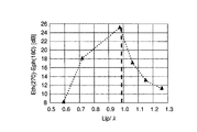
図21は、垂直部23と垂直部24との間隔と放射効率との関係を示す図である。この図21から分かるように、垂直部23と垂直部24との間隔が0.1波長以上になると、放射効率が十分に大きく得られる。このため、垂直部23と垂直部24との間隔を0.1波長以上とすることが望ましい。
FIG. 21 is a diagram showing the relationship between the distance between the
このようにすることで本実施形態の携帯無線通信装置では、給電手段4は不平衡給電を行うから、給電手段4にバランを設ける必要が無く、バランを使用することにより生じる種々の不具合を回避することができる。そして本実施形態では、不平衡給電を行っていながら、前方向への放射を良好に抑圧することができる。しかも本実施形態によれば、アンテナ2はループ部を持つものの、このループ部のループ長Llpは1波長であるから、2波長ループアンテナに比べて小型化が可能である。
By doing so, in the portable wireless communication device of the present embodiment, the power feeding unit 4 performs unbalanced power feeding, so there is no need to provide a balun in the power feeding unit 4, and various problems caused by using the balun are avoided. can do. In the present embodiment, it is possible to satisfactorily suppress forward radiation while performing unbalanced power feeding. In addition, according to this embodiment, although the
また、アンテナ2の外形は、筐体1の前面に沿った扁平形状をなす。このため、筐体1を図1に示すように前後方向の厚みが小さい薄型の形状とする場合に、アンテナ2を筐体1の内部に効率的に収容することが可能となる。これらの結果、コンパクトでありながら、人体が筐体1の前面に近接することによる通信性能の劣化を軽減することが可能な携帯電話装置となる。また、筐体1がこのような薄型をなしている場合には、回路基板3等がアンテナ2と平行して配置される。このような場合における回路基板3等に向けた放射は、回路基板3等による減衰を受けて大きな損失が起きる恐れがある。しかし本実施形態によれば、回路基板3等が配置される方向へ放射される電磁界は抑制されているから、上記のような回路基板3等による損失を抑えられる。
In addition, the outer shape of the
なお、以上の実施形態は以下のような変形実施が可能である。
例えば垂直部23,24,25,26の端部をさらに折り曲げた形状とするなど、アンテナ2の形状は任意に変更が可能である。ただし、アンテナ2における上側半分および下側半分のそれぞれの形状の対称度が低下するほど、放射パターンの上下バランスがくずれる。また、左側半分および右側半分のそれぞれの形状の対称度が低下するほど、放射パターンの左右バランスがくずれる。そこで、上側半分および下側半分のそれぞれの形状の対称度および左側半分および右側半分のそれぞれの形状の対称度ができるだけ高くなる形状とすることが望ましい。
携帯無線通信装置に限らず、他の種類の無線通信装置として実現することも可能である。
The above embodiment can be modified as follows.
For example, the shape of the
Not only a portable wireless communication device but also other types of wireless communication devices can be realized.
なお、本発明は上記実施形態そのままに限定されるものではなく、実施段階ではその要旨を逸脱しない範囲で構成要素を変形して具体化できる。また、上記実施形態に開示されている複数の構成要素の適宜な組み合わせにより、種々の発明を形成できる。例えば、実施形態に示される全構成要素から幾つかの構成要素を削除してもよい。さらに、異なる実施形態にわたる構成要素を適宜組み合わせてもよい。 Note that the present invention is not limited to the above-described embodiment as it is, and can be embodied by modifying the constituent elements without departing from the scope of the invention in the implementation stage. In addition, various inventions can be formed by appropriately combining a plurality of components disclosed in the embodiment. For example, some components may be deleted from all the components shown in the embodiment. Furthermore, constituent elements over different embodiments may be appropriately combined.
1…筐体、2…アンテナ、3…回路基板、4…給電手段、21,22…水平部、23,24,25,26…垂直部、27,28…短絡部。
DESCRIPTION OF
Claims (5)
給電手段が接続される第1の部位と、
前記第1の部位に対して第1の方向に離間して対向するとともに前記給電手段が接続されない第2の部位と、
それぞれが両端が開放した前記動作周波数の0.5波長のダイポールアンテナとして機能し、かつ前記第1の方向に直交する第2の方向に離間して対向する2本のダイポール部とを具備するとともに、
前記2本のダイポール部の一方の一部分が、前記第1の部位の一端と前記第2の部位の一端とを接続するとともに、前記2本のダイポール部の他方の一部分が、前記第1の部位の他端と前記第2の部位の他端とを接続しており、
さらに前記第1の部位、前記第2の部位および前記2本のダイポール部のそれぞれの前記一部分は、前記動作周波数の1波長にほぼ対応する長さを持った部位を形成していることを特徴とするアンテナ。 An antenna having a predetermined operating frequency,
A first part to which the power supply means is connected;
A second part that is spaced apart and opposed to the first part in the first direction and the power supply means is not connected;
Each of the two functions as a 0.5-wave dipole antenna with the operating frequency open at both ends, and has two dipole portions that are spaced apart and face each other in a second direction orthogonal to the first direction. ,
One part of the two dipole parts connects one end of the first part and one end of the second part, and the other part of the two dipole parts is the first part. Is connected to the other end of the second part,
Further, each of the first portion, the second portion, and the two dipole portions forms a portion having a length substantially corresponding to one wavelength of the operating frequency. And antenna.
前記アンテナに給電する給電手段とを具備し、
前記アンテナは、前記給電手段が接続される第1の部位と、前記第1の部位に対して第1の方向に離間して対向するとともに前記給電手段が接続されない第2の部位と、それぞれが両端が開放した前記動作周波数の0.5波長のダイポールアンテナとして機能し、かつ前記第1の方向に直交する第2の方向に離間して対向する2本のダイポール部とを備えるとともに、前記2本のダイポール部の一方の一部分が、前記第1の部位の一端と前記第2の部位の一端とを接続するとともに、前記2本のダイポール部の他方の一部分が、前記第1の部位の他端と前記第2の部位の他端とを接続しており、さらに前記第1の部位、前記第2の部位および前記2本のダイポール部のそれぞれの前記一部分は、前記電波の1波長にほぼ対応する長さを持った部位を形成しており、
前記給電手段は、前記第1の部位に不平衡給電することを特徴とする無線通信装置。 An antenna having a predetermined operating frequency;
Power supply means for supplying power to the antenna,
The antenna includes a first part to which the power feeding unit is connected, and a second part to which the power feeding unit is not connected while being spaced apart from the first part in the first direction. 2 dipole antennas that function as a 0.5-wave dipole antenna whose operating frequency is open at both ends and that are spaced apart and face each other in a second direction orthogonal to the first direction, One part of the two dipole parts connects one end of the first part and one end of the second part, and the other part of the two dipole parts is the other part of the first part. An end and the other end of the second part are connected, and each of the first part, the second part, and the two dipole portions is approximately at one wavelength of the radio wave. With corresponding length Position forms a,
The wireless communication apparatus, wherein the power supply means supplies unbalanced power to the first part.
Priority Applications (4)
| Application Number | Priority Date | Filing Date | Title |
|---|---|---|---|
| JP2004005437A JP3848328B2 (en) | 2004-01-13 | 2004-01-13 | Antenna and wireless communication apparatus equipped with the antenna |
| EP04020907A EP1555720A1 (en) | 2004-01-13 | 2004-09-02 | A dipole antenna and radio communication device provided with the same |
| US10/947,528 US7109936B2 (en) | 2004-01-13 | 2004-09-22 | Antenna and radio communication device provided with the same |
| CNA2004100120029A CN1641932A (en) | 2004-01-13 | 2004-09-27 | Antenna and radio communication device provided with the same |
Applications Claiming Priority (1)
| Application Number | Priority Date | Filing Date | Title |
|---|---|---|---|
| JP2004005437A JP3848328B2 (en) | 2004-01-13 | 2004-01-13 | Antenna and wireless communication apparatus equipped with the antenna |
Publications (2)
| Publication Number | Publication Date |
|---|---|
| JP2005203853A JP2005203853A (en) | 2005-07-28 |
| JP3848328B2 true JP3848328B2 (en) | 2006-11-22 |
Family
ID=34616836
Family Applications (1)
| Application Number | Title | Priority Date | Filing Date |
|---|---|---|---|
| JP2004005437A Expired - Fee Related JP3848328B2 (en) | 2004-01-13 | 2004-01-13 | Antenna and wireless communication apparatus equipped with the antenna |
Country Status (4)
| Country | Link |
|---|---|
| US (1) | US7109936B2 (en) |
| EP (1) | EP1555720A1 (en) |
| JP (1) | JP3848328B2 (en) |
| CN (1) | CN1641932A (en) |
Families Citing this family (16)
| Publication number | Priority date | Publication date | Assignee | Title |
|---|---|---|---|---|
| US7145515B1 (en) * | 2004-01-02 | 2006-12-05 | Duk-Yong Kim | Antenna beam controlling system for cellular communication |
| JP3791923B2 (en) * | 2004-01-13 | 2006-06-28 | 株式会社東芝 | Wireless communication terminal |
| KR100826115B1 (en) * | 2006-09-26 | 2008-04-29 | (주)에이스안테나 | Folded dipole antenna having bending shape for improving beam width tolerance |
| JP4762126B2 (en) * | 2006-12-20 | 2011-08-31 | 株式会社東芝 | Electronics |
| JP2008250573A (en) * | 2007-03-29 | 2008-10-16 | Brother Ind Ltd | Antenna device and radio tag communication apparatus |
| JP2009152722A (en) * | 2007-12-19 | 2009-07-09 | Toshiba Corp | Antenna unit and radio equipment |
| JP2010124402A (en) * | 2008-11-21 | 2010-06-03 | Panasonic Electric Works Co Ltd | Tag reader and authentication system |
| CN101908668B (en) * | 2009-06-08 | 2013-07-03 | 深圳富泰宏精密工业有限公司 | Broadband antenna |
| US10027030B2 (en) | 2013-12-11 | 2018-07-17 | Nuvotronics, Inc | Dielectric-free metal-only dipole-coupled broadband radiating array aperture with wide field of view |
| JP6212405B2 (en) * | 2014-02-19 | 2017-10-11 | シャープ株式会社 | transceiver |
| US10195445B2 (en) * | 2015-06-11 | 2019-02-05 | Cardiac Pacemakers, Inc. | Bent loop antenna for implantable medical devices |
| US10431896B2 (en) | 2015-12-16 | 2019-10-01 | Cubic Corporation | Multiband antenna with phase-center co-allocated feed |
| GB2578388A (en) | 2017-06-20 | 2020-05-06 | Cubic Corp | Broadband antenna array |
| WO2019209461A1 (en) | 2018-04-25 | 2019-10-31 | Nuvotronics, Inc. | Microwave/millimeter-wave waveguide to circuit board connector |
| US11367948B2 (en) | 2019-09-09 | 2022-06-21 | Cubic Corporation | Multi-element antenna conformed to a conical surface |
| CN210489813U (en) * | 2019-09-27 | 2020-05-08 | 深圳市安拓浦科技有限公司 | Dipole antenna structure |
Family Cites Families (18)
| Publication number | Priority date | Publication date | Assignee | Title |
|---|---|---|---|---|
| DK168780B1 (en) * | 1992-04-15 | 1994-06-06 | Celwave R F A S | Antenna system and method of manufacture thereof |
| US5808584A (en) * | 1996-05-30 | 1998-09-15 | Ntl Technologies Corporation | Dipole television antenna |
| JPH1032418A (en) | 1996-07-18 | 1998-02-03 | Dx Antenna Co Ltd | Flat antenna |
| US6138050A (en) * | 1997-09-17 | 2000-10-24 | Logitech, Inc. | Antenna system and apparatus for radio-frequency wireless keyboard |
| US6317099B1 (en) * | 2000-01-10 | 2001-11-13 | Andrew Corporation | Folded dipole antenna |
| AU778969B2 (en) * | 1999-11-03 | 2004-12-23 | Andrew Corporation | Folded dipole antenna |
| US6285336B1 (en) * | 1999-11-03 | 2001-09-04 | Andrew Corporation | Folded dipole antenna |
| JP2002009534A (en) | 2000-03-01 | 2002-01-11 | Matsushita Electric Ind Co Ltd | Built-in antenna for wireless communication terminal |
| JP2001339215A (en) | 2000-05-30 | 2001-12-07 | Matsushita Electric Ind Co Ltd | Antenna and radio device |
| US6535175B2 (en) * | 2000-06-01 | 2003-03-18 | Intermec Ip Corp. | Adjustable length antenna system for RF transponders |
| JP2002198723A (en) * | 2000-11-02 | 2002-07-12 | Ace Technol Co Ltd | Wideband directional antenna |
| TW529205B (en) | 2001-05-24 | 2003-04-21 | Rfwaves Ltd | A method for designing a small antenna matched to an input impedance, and small antennas designed according to the method |
| US6842158B2 (en) * | 2001-12-27 | 2005-01-11 | Skycross, Inc. | Wideband low profile spiral-shaped transmission line antenna |
| US6720926B2 (en) * | 2002-06-27 | 2004-04-13 | Harris Corporation | System for improved matching and broadband performance of microwave antennas |
| US6731246B2 (en) * | 2002-06-27 | 2004-05-04 | Harris Corporation | Efficient loop antenna of reduced diameter |
| JP4363936B2 (en) * | 2002-09-26 | 2009-11-11 | パナソニック株式会社 | Antenna for wireless terminal device and wireless terminal device |
| JP3824579B2 (en) | 2002-12-19 | 2006-09-20 | 株式会社東芝 | Antenna device, portable wireless communication device, and connection member |
| US6933907B2 (en) * | 2003-04-02 | 2005-08-23 | Dx Antenna Company, Limited | Variable directivity antenna and variable directivity antenna system using such antennas |
-
2004
- 2004-01-13 JP JP2004005437A patent/JP3848328B2/en not_active Expired - Fee Related
- 2004-09-02 EP EP04020907A patent/EP1555720A1/en not_active Withdrawn
- 2004-09-22 US US10/947,528 patent/US7109936B2/en not_active Expired - Fee Related
- 2004-09-27 CN CNA2004100120029A patent/CN1641932A/en active Pending
Also Published As
| Publication number | Publication date |
|---|---|
| EP1555720A1 (en) | 2005-07-20 |
| JP2005203853A (en) | 2005-07-28 |
| US7109936B2 (en) | 2006-09-19 |
| CN1641932A (en) | 2005-07-20 |
| US20050151691A1 (en) | 2005-07-14 |
Similar Documents
| Publication | Publication Date | Title |
|---|---|---|
| JP3848328B2 (en) | Antenna and wireless communication apparatus equipped with the antenna | |
| US7158820B2 (en) | Mobile communication terminal | |
| US7358906B2 (en) | Antenna device and mobile communication terminal equipped with antenna device | |
| JP4372156B2 (en) | ANTENNA DEVICE AND RADIO TERMINAL USING THE ANTENNA DEVICE | |
| US6924769B2 (en) | Antenna for communication terminal apparatus | |
| JP5301608B2 (en) | Antenna for wireless terminal equipment | |
| JP4171008B2 (en) | Antenna device and portable radio | |
| JP5327322B2 (en) | Antenna module | |
| JP5269927B2 (en) | Dual band antenna | |
| JP2007081712A (en) | Walkie talkie and antenna assembly | |
| JPWO2007043150A1 (en) | Antenna device for portable terminal and portable terminal | |
| US9306275B2 (en) | Multi-antenna and electronic device | |
| JPWO2009050883A1 (en) | Array antenna device | |
| JPWO2013015264A1 (en) | Antenna device | |
| JP2012209619A (en) | Directivity variable antenna | |
| JP4263961B2 (en) | Antenna device for portable radio | |
| JP3824579B2 (en) | Antenna device, portable wireless communication device, and connection member | |
| JP2004242165A (en) | Portable radio equipment | |
| JPH08186425A (en) | Miniaturized antenna and diversity antenna | |
| JP2006197138A (en) | Multi-frequency sharing antenna device and diversity antenna device constituted of the same | |
| JP2007215133A (en) | Dipole antenna and multi-antenna unit | |
| CN108432048A (en) | A kind of slot antenna and terminal | |
| JP5885011B1 (en) | Antenna device and communication device | |
| JP5799247B2 (en) | Portable radio | |
| JP2006319772A (en) | Diversity device |
Legal Events
| Date | Code | Title | Description |
|---|---|---|---|
| A977 | Report on retrieval |
Free format text: JAPANESE INTERMEDIATE CODE: A971007 Effective date: 20060116 |
|
| A131 | Notification of reasons for refusal |
Free format text: JAPANESE INTERMEDIATE CODE: A131 Effective date: 20060124 |
|
| A521 | Written amendment |
Free format text: JAPANESE INTERMEDIATE CODE: A523 Effective date: 20060327 |
|
| A131 | Notification of reasons for refusal |
Free format text: JAPANESE INTERMEDIATE CODE: A131 Effective date: 20060418 |
|
| A521 | Written amendment |
Free format text: JAPANESE INTERMEDIATE CODE: A523 Effective date: 20060619 |
|
| TRDD | Decision of grant or rejection written | ||
| A01 | Written decision to grant a patent or to grant a registration (utility model) |
Free format text: JAPANESE INTERMEDIATE CODE: A01 Effective date: 20060822 |
|
| A61 | First payment of annual fees (during grant procedure) |
Free format text: JAPANESE INTERMEDIATE CODE: A61 Effective date: 20060824 |
|
| FPAY | Renewal fee payment (event date is renewal date of database) |
Free format text: PAYMENT UNTIL: 20090901 Year of fee payment: 3 |
|
| FPAY | Renewal fee payment (event date is renewal date of database) |
Free format text: PAYMENT UNTIL: 20100901 Year of fee payment: 4 |
|
| FPAY | Renewal fee payment (event date is renewal date of database) |
Free format text: PAYMENT UNTIL: 20110901 Year of fee payment: 5 |
|
| FPAY | Renewal fee payment (event date is renewal date of database) |
Free format text: PAYMENT UNTIL: 20110901 Year of fee payment: 5 |
|
| FPAY | Renewal fee payment (event date is renewal date of database) |
Free format text: PAYMENT UNTIL: 20120901 Year of fee payment: 6 |
|
| FPAY | Renewal fee payment (event date is renewal date of database) |
Free format text: PAYMENT UNTIL: 20120901 Year of fee payment: 6 |
|
| FPAY | Renewal fee payment (event date is renewal date of database) |
Free format text: PAYMENT UNTIL: 20130901 Year of fee payment: 7 |
|
| LAPS | Cancellation because of no payment of annual fees |