JP3847965B2 - Imaging device - Google Patents
Imaging device Download PDFInfo
- Publication number
- JP3847965B2 JP3847965B2 JP21569498A JP21569498A JP3847965B2 JP 3847965 B2 JP3847965 B2 JP 3847965B2 JP 21569498 A JP21569498 A JP 21569498A JP 21569498 A JP21569498 A JP 21569498A JP 3847965 B2 JP3847965 B2 JP 3847965B2
- Authority
- JP
- Japan
- Prior art keywords
- hue
- color
- white balance
- control means
- subject
- Prior art date
- Legal status (The legal status is an assumption and is not a legal conclusion. Google has not performed a legal analysis and makes no representation as to the accuracy of the status listed.)
- Expired - Fee Related
Links
Images


Classifications
-
- H—ELECTRICITY
- H04—ELECTRIC COMMUNICATION TECHNIQUE
- H04N—PICTORIAL COMMUNICATION, e.g. TELEVISION
- H04N23/00—Cameras or camera modules comprising electronic image sensors; Control thereof
- H04N23/70—Circuitry for compensating brightness variation in the scene
- H04N23/74—Circuitry for compensating brightness variation in the scene by influencing the scene brightness using illuminating means
-
- H—ELECTRICITY
- H04—ELECTRIC COMMUNICATION TECHNIQUE
- H04N—PICTORIAL COMMUNICATION, e.g. TELEVISION
- H04N23/00—Cameras or camera modules comprising electronic image sensors; Control thereof
- H04N23/80—Camera processing pipelines; Components thereof
- H04N23/84—Camera processing pipelines; Components thereof for processing colour signals
- H04N23/88—Camera processing pipelines; Components thereof for processing colour signals for colour balance, e.g. white-balance circuits or colour temperature control
Description
【0001】
【発明の属する技術分野】
本発明は、閃光発光装置を使用可能な撮像装置に関するものである。
【0002】
【従来の技術】
従来、電子カメラなどの撮像装置に於いて照度の低い被写体を撮影する場合や、逆光状態の被写体を撮影する場合に閃光発光装置(ストロボ)を用いることが必要不可欠になっている。
【0003】
一方、撮像装置では被写体の色温度に応じてホワイトバランスを調整する必要があるが、人工照明の場合演色性が悪く、ホワイトバランスだけ補正しても屋外光に対して色バランスが適切にならないものが多い。そのため、ホワイトバランスに応じて色相や彩度を補正する手法が考案されている。以下、図面を用いて従来例について説明する。
【0004】
図6は従来の電子カメラの撮像系のブロック図である。201はレンズ、202は光学絞り装置、203は撮像素子、204は撮像素子の出力から輝度信号を生成する輝度生成回路、205はγ処理や輪郭強調などを行う輝度信号処理回路、206はRGB3色の色信号を生成する色分離回路、207はR信号及びB信号の利得を変えてホワイトバランスを制御するホワイトバランスアンプ、208はホワイトバランスアンプ207を通ったRGB信号から色差信号R−Y、B−Yを生成する色差マトリクス回路、209は色相を調整するリニアマトリクス回路、210は色差信号R−Y、B−Yの夫々の利得を制御し色飽和度を調整する色差利得回路、211は輝度信号と色差信号からビデオ信号を生成するエンコーダ回路、212は色差信号から色温度情報を抽出しホワイトバランスアンプ207の利得を制御するホワイトバランス制御回路、213はホワイトバランス制御回路212からのホワイトバランス情報から色相及び彩度の補正制御を行う色相補正回路、214は閃光発光装置、215は閃光発光装置214の発光タイミングや発光量を制御するストロボ制御回路である。
【0005】
レンズ201を通って入射した光は光学絞り装置202で露光量制御された後、撮像素子203で光電変換され電荷として蓄積される。撮像素子203から出力された映像信号は輝度生成回路204によって輝度信号系と色信号系に分配され、輝度信号Yは輝度信号処理回路205によってγ処理や輪郭強調処理などを施される。
【0006】
一方、色信号は色分離回路206によってR、G、Bの3色に分離される。RGB信号はホワイトバランスアンプ207によってホワイトバランスを調整され、γ処理を施されて色差マトリクス回路208に入力され、R−Y、B−Yの色差信号に変換される。生成された色差信号はリニアマトリクス回路209で色相の調整が施される。
【0007】
リニアマトリクス回路209の出力は色差利得回路210に入力されR−Y、B−Y夫々の利得が調整される。色差利得回路209の出力はエンコーダ回路211でビデオ信号にエンコードされると共にホワイトバランス制御回路212に供給され、ホワイトバランス回路212は色差信号をもとに色温度検出を行う。ホワイトバランス回路212は検出した色温度に対応したホワイトバランスアンプ207の利得を演算し、ホワイトバランス制御を行う。
【0008】
またストロボ制御回路215は撮像素子203の蓄積期間中に閃光発光装置214を発光させ、輝度信号Yに基づいて発光量を制御する。
【0009】
ところで、被写体の色温度は照明光源の種類によって異なるが、人工照明の場合演色性が悪く、ホワイトバランスだけ補正しても屋外光に対して色バランスが適切にならないものが多い。そのため、ホワイトバランスに応じて色相や彩度を補正する必要がある。
【0010】
ホワイトバランス制御回路212はホワイトバランス補正情報を色相補正回路213に供給し、色相補正回路213はホワイトバランス補正情報から最適な色相を算出してリニアマトリクス回路209および色差利得回路210を制御する。さて、ここで言うリニアマトリクス回路209の出力は以下の2式で与えられる。
【0011】
(R−Y)’=(R−Y)+α(B−Y) (−1<α<1) ‥‥‥ (1)
(B−Y)’=(B−Y)+β(R−Y) (−1<β<1) ‥‥‥ (2)
(1)、(2)式によればリニアマトリクス回路208の係数α、βを変えることによって色差信号の色相を調整することが出来る。色相補正回路213はリニアマトリクス回路209のα、βを制御する。
【0012】
また、閃光発光装置214を使用する場合、被写体の光源や閃光発光装置の発光量などに応じてホワイトバランスを補正する必要がある。ストロボ制御回路215は輝度信号等から得た被写体の光量と、閃光発光装置の発光量をホワイトバランス制御回路212に与え、ホワイトバランス制御回路212はそれらを元に閃光発光装置214を使用した場合のホワイトバランス制御を行う。
【0013】
【発明が解決しようとする課題】
しかしながら、上記従来例の撮像装置ではストロボ使用時にホワイトバランスは補正できるが、色相や彩度はストロボの演色性に適していない。
【0014】
図5は屋外光(太陽光)とストロボ光の分光分布図である。同図の分光分布からもわかるように、ストロボ光は屋外光に対して演色性が低く、色温度の差ばかりでなく、カラーバランスにも影響を与える。
【0015】
したがって、屋外光と同じ色相のままストロボ撮影を行っても最適なカラーバランスを得ることができない場合があった。
【0016】
そこで、本願の課題は、閃光発光装置を使用して撮影した場合に最適なカラーバランスを得ることができる撮像装置を提供することにある。
【0017】
【課題を解決するための手段】
上記の課題を解決するために、本発明における請求項1に記載の発明によれば、閃光発光装置を使用する撮像装置であって、
前記閃光発光装置の発光量を制御する発光量制御手段と、
被写体からの光を撮像信号に変換する撮像手段と、
前記撮像信号のホワイトバランス処理を行うホワイトバランス制御手段と、
前記ホワイトバランス制御手段によってホワイトバランス処理された撮像信号の色相または色飽和度を制御する色調整手段と、
前記発光量制御手段によって決定された発光量に従って色相または色飽和度を補正するように前記色調整手段を制御する第1の色相制御手段と、
前記第1の色相制御手段は、前記ホワイトバランス制御手段のホワイトバランス処理とは独立して前記色相または色飽和度を補正するように前記色調整手段を制御することを特徴とする。
【0018】
本願における請求項4に記載の発明によれば、
閃光発光装置を使用する撮像装置であって、
前記被写体からの光を撮像信号に変換する撮像手段と、
被写体の照度を検出する照度検出手段と、
前記被写体の照度を用いて前記撮像信号のホワイトバランス処理を行うホワイトバランス制御手段と、
前記ホワイトバランス制御手段によってホワイトバランス処理された撮像信号の色相または色飽和度を制御する色調整手段と、
前記照度検出手段によって検出された被写体の照度に従って色相または色飽和度を補正するように色調整手段を制御する第1の色相制御手段と、を有し、
前記第1の色相制御手段は、前記ホワイトバランス制御手段のホワイトバランス処理とは独立して前記色相または色飽和度を補正するように前記色調整手段を制御することを特徴とする。
【0019】
本願における請求項7に記載の発明によれば、閃光発光装置を使用する撮像装置であって、
被写体からの光を撮像信号に変換する撮像手段と、
前記被写体の色温度を検出する色温度検出手段と、
前記被写体の照度を検出する照度検出手段と、
閃光発光装置の発光量を制御する発光量制御手段と、
前記被写体の色温度と照度に基づいて前記撮像信号のホワイトバランス処理を行うホワイトバランス制御手段と、
前記ホワイトバランス制御手段によってホワイトバランス処理された撮像信号の色相または色飽和度を制御する色調整手段と、
前記照度検出手段によって検出された被写体照度とかつ/または前記発光量制御手段によって決定された発光量にしたがって色相または色飽和度を補正するように前記色調整手段を制御する第1の色相制御手段と、
前記色温度検出手段によって検出された被写体の色温度に応じて色相または色飽和度を補正するように前記色調整手段を制御する第2の色相制御手段と、を有し、前記第1の色相制御手段は、前記第2の色相制御手段とは独立して前記被写体照度かつ/または前記発光量制御手段によって決定された発光量にしたがって色相または色飽和度を補正するように前記色調整手段を制御することを特徴とする。
【0031】
【発明の実施の形態】
以下本願発明を、各図を参照しながら、その実施の形態について、詳細に説明する。
【0032】
(第1の実施例)
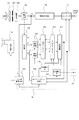
図1は本発明の特徴を最もよく表す図面であり、閃光発光装置を使用して撮影した場合に最適なカラーバランスを得ることが出来るようにした撮像装置の構成を示すブロック図である。
【0033】
同図において、101は撮影レンズ、102は光学絞り装置、103は撮像素子、104は撮像素子の出力から輝度信号を生成する輝度生成回路、105はγ処理や輪郭強調などを行う輝度信号処理回路、106はRGB3色の色信号を生成する色分離回路、107はR及びB信号の利得を変えてホワイトバランスを制御するホワイトバランスアンプ、108はホワイトバランスアンプ107を通ったRGB信号から色差信号R−Y、B−Yを生成する色差マトリクス回路である。
【0034】
109は、色差マトリクス回路108より出力される色差信号R−Y、B−Yを入力して色相を調整するリニアマトリクス回路、110は色差信号R−Y、B−Yの夫々の利得を制御し色飽和度を調整する色差利得回路、111は輝度信号と色差信号からビデオ信号を生成するエンコーダ回路、112は色差信号から色温度情報を抽出しホワイトバランスアンプ107の利得を制御するホワイトバランス制御回路、113はホワイトバランス制御回路112からのホワイトバランス情報から色相及び彩度の補正制御を行う色相補正回路Aである。
【0035】
114は閃光発光装置、115は閃光発光装置114の発光タイミングや発光量を制御するストロボ制御回路、116はストロボ制御回路115からの閃光発光装置の発光量情報から色相及び彩度の補正制御を行う色相補正回路Bである。
【0036】
101から115までの信号の流れおよび各ブロックの動作は、図6に示す従来例の201から215までの構成と同様のものである。
【0037】
ストロボ制御回路115は輝度信号等から得た被写体の光量と閃光発光装置の発光量の情報をホワイトバランス制御回路112および色補正回路B116に供給する。
【0038】
ホワイトバランス制御回路112は前述の従来例と同様に被写体の光量と閃光発光装置の発光量を元に閃光発光装置114を使用した場合のホワイトバランス制御を行う。
【0039】
色補正回路B116は本実施形態の特徴的な部分であり、ストロボ制御回路115を介して供給される輝度Y信号レベルによって検出される被写体の光量と、閃光発光装置の発光量とを含む情報Scを元に閃光発光装置114を使用した場合のカラーバランスの補正を行う。カラーバランスの補正はリニアマトリクス回路109および色差利得回路110を制御することによって行われる。
【0040】
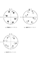
図2は白熱灯光源と蛍光灯光源を例にカラーバランスのずれを比較するためのR−Y,B−Y色差信号座標におけるベクトル図である。
【0041】
同図a)は理想的な光源でカラーバーチャートを撮影したベクトル図、同図b)は白熱灯光源でカラーバーチャートを撮影したベクトル図、同図c)は蛍光灯光源でカラーバーチャートを撮影したベクトル図である。
【0042】
各図において、白抜きの矩形で示すベクトル位置は、撮影しているカラーバーチャートの各色の色差座標上におけるベクトル位置を示し、網掛けの円あるいは楕円径で示すベクトル座標は、検出されている色信号のベクトルを示すものである。
【0043】
同図a)は理想的な光源でカラーバーチャートを撮像した場合を示すもので、本来の色が忠実に再現されているものとする。
【0044】
同図b)は照明に白熱灯を用いた場合を示すものであり、白熱灯光源下では理想的な光源に対してRが伸び、Yeが縮む。
【0045】
また同図c)の蛍光灯光源下では理想的な光源に対してRが縮み、Yeが伸びる。これを補正するのが従来から用いられている色相補正回路213であり、また本実施形態の構成で見れば、色相補正回路A113である。
【0046】
図3は白熱灯光源を例にカラーバランス補正の状態を説明する図である。同図a)は白熱灯光源でホワイトバランスを合わせ、カラーバランスの補正を行わない場合のベクトル図である。これに対しカラーバランス補正を加えたのが、同図b)である。この補正はR−Yを圧縮しB−Yを伸長するとともに、リニアマトリクスの補正もかけている。
【0047】
この補正状態でストロボ撮影を行った場合を示すのが同図c)である。
【0048】
ストロボ光は白熱灯光源よりも理想のカラーバランスに近いため、同図b)に示す白熱灯光源に対するカラーバランス補正を行っていることにより逆にバランスが崩れてしまう。
【0049】
そして、このカラーバランスは、被写体光源の明るさとストロボ光の明るさによって変わってくる。例えばストロボ光が弱い場合には被写体光源の、この場合は白熱灯光源に対するカラーバランスに近くなり、ストロボ光が強い場合には、ストロボ光に対するカラーバランスに近くなるわけである。
【0050】
同図d)は同図c)の状態に対して、さらにカラーバランス補正を加えたものである。同図c)の状態の被写体光量とストロボ発光量から算出した補正値をかけることにより様々な被写体やストロボ発光量に対して最適なバランスを得ることが出来る。
【0051】
すなわちストロボ発光量と、被写体の光源との明るさの割合によって、白熱灯光源に対する補正と、ストロボ発光量に基づく補正の割合を正確に演算し、最適なカラーバランス補正を行うようにしたものである。
【0052】
被写体光源の明るさと、ストロボの発光量から、白熱灯光源に対する補正量、すなわち同図a)の状態から同図b)の状態へと補正するための補正量と、ストロボ発光に対する補正量、すなわち同図c)の状態を同図d)の状態へと補正するための補正量を、それぞれ被写体光源の明るさと、ストロボ発光量に応じて、且つ両者の比率に応じて最適化し、全体的なカラーバランスの最適化を図るようにしたものである。
【0053】
図3では、a)から順を追ってd)へと移行するように説明したが、実際の制御は、被写体光源の明るさと演算されたストロボ発光量から、直接同図d)の状態に補正することができる。
【0054】
このように閃光発光装置を使用して撮影する場合に被写体照度もしくはストロボ発光量に応じてカラーバランスを補正することにより、あらゆるストロボ撮影において最適なカラーバランスで撮影することが可能になる。
【0055】
上述の実施形態では、被写体光量とストロボ発光量を元にカラーバランスを補正したが、そのどちらか一方によってカラーバランスを補正するようにしてもよい。すなわち被写体光量にもとづいてストロボ発光の有無及び発光量を演算すれば、ストロボ発光時のカラーバランスを制御することができるし、実際のストロボ発光量からでも、カラーバランスを制御することができる。
【0056】
またカラーバランスの補正量はストロボ発光量に応じて、図1に点線で示すメモリ117等の形態で、テーブルデータで持つようにしても、また直線近似などで補間演算してもよい。
【0057】
また、ホワイトバランスによる補正は元々無くても実施例の効果は期待できるし、単純にストロボ専用の補正値を持っているだけでも補正は可能である。カラーバランスの補正はリニアマトリクス回路で説明したが、その他の色相調整手段でもよいことは言うまでもない。
【0058】
(第2の実施形態)
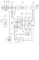
図4は本発明の第2の実施形態を示す図面であり、ストロボ使用時に専用のカラーバランス補正を行い、簡易的にストロボ撮影に適したカラーバランスを得ることを可能とした。
【0059】
ストロボ撮影可能な撮像装置のブロック図である。図中301から311はそれぞれ図1の101から111に、図中314、315はそれぞれ第1図の114、115に対応する。317は色相データを元に色相補正制御を行う色相補正回路、318はストロボ未使用時の色相データを出力する出力データA、319はストロボ使用時に適した色相データを出力する出力データB、320は出力データA318と出力データB319を切りかえるスイッチである。
【0060】
図4中の映像信号の流れは第1の実施例とほぼ共通のものである。ストロボ制御回路315はストロボを使用する場合と使用しない場合でスイッチ320を切り替える。スイッチ320はストロボ未使用時にはメモリ等に記憶されている色相データB318を選択し、ストロボ使用時には色相データA319を選択する。
【0061】
ここで、閃光発光装置の演色性について説明する。図5は太陽光と閃光発光装置の分光分布図である。図5a)は太陽光の分光分布で、演色性の基準となる光である。通常は太陽光でカラーバーチャートを撮影した場合のカラーバランスが最適となるように色相を設定し、出力データA318がこれに当たる。図5b)は閃光発光装置の分光分布で、比較的演色性は高いものの100%にはならない。
【0062】
閃光発光装置を使用してカラーバーチャートを撮影した場合のカラーバランスが最適となるように色相を設定したものが出力データB319である。
【0063】
このように閃光発光装置を使用して撮影する場合に閃光発光装置専用のカラーバランスデータを使用することにより、ストロボ撮影において最適なカラーバランスで撮影することが可能になる。
【0064】
尚、本実施例はストロボ未使用時は太陽光に合わせた色相データを使用したが、その他の光源に適した色相データを用いても良いし、ストロボ以外の要因で複数の色相データを切り替えて用いても構わない。カラーバランスの補正はリニアマトリクス回路で説明したが、その他の色相調整手段でも構わないことは言うまでもない。
【0065】
【発明の効果】
以上述べたように、本願によれば、色温度すなわちホワイトバランス処理とは独立して、ストロボの発光量、被写体照度、あるいはストロボの発光量と被写体照度の両方に応じて色相や色飽和度を変えることが可能になるため、適切なホワイトバランス処理を行った上で、さらに、例えば、ストロボ等の人工照明の演色性も考慮した最適なカラーバランスを得ることが出来る。
【図面の簡単な説明】
【図1】本発明の第1の実施例を示すブロック図である。
【図2】各種光源のカラーバランスを示すベクトル図である。
【図3】本発明の第1の実施例のカラーバランス補正の概念図である。
【図4】本発明の第2の実施例を示すブロック図である。
【図5】閃光発光装置の分光分布図である。
【図6】従来例の構成を示すブロック図である。
【符号の説明】
101 レンズ
102 絞り
103 撮像素子
104 輝度生成回路
105 輝度信号処理回路
106 色分離回路
107 利得制御回路
108 色差マトリクス回路
109 リニアマトリクス回路
110 色差利得回路
111 エンコーダ回路
112 ホワイトバランス制御回路
113 色相補正回路A
114 閃光発光装置
115 ストロボ制御回路
116 色相補正回路B[0001]
BACKGROUND OF THE INVENTION
The present invention relates to an imaging device that can use a flash light emitting device.
[0002]
[Prior art]
Conventionally, it has become indispensable to use a flash light emitting device (strobe) when photographing an object with low illuminance in an imaging device such as an electronic camera or photographing a subject in a backlight state.
[0003]
On the other hand, it is necessary to adjust the white balance according to the color temperature of the subject in the imaging device, but in the case of artificial lighting, the color rendering is poor, and even if only the white balance is corrected, the color balance is not appropriate for outdoor light There are many. Therefore, a method for correcting the hue and saturation according to the white balance has been devised. Hereinafter, a conventional example will be described with reference to the drawings.
[0004]
FIG. 6 is a block diagram of an imaging system of a conventional electronic camera. 201 is a lens, 202 is an optical aperture device, 203 is an image sensor, 204 is a luminance generation circuit that generates a luminance signal from the output of the image sensor, 205 is a luminance signal processing circuit that performs gamma processing, contour enhancement, and the like, and 206 is RGB three
[0005]
The light incident through the
[0006]
On the other hand, the color signal is separated into three colors of R, G, and B by the
[0007]
The output of the
[0008]
The
[0009]
By the way, although the color temperature of the subject varies depending on the type of illumination light source, in the case of artificial illumination, color rendering is poor, and even when only white balance is corrected, color balance is often not appropriate for outdoor light. Therefore, it is necessary to correct the hue and saturation according to the white balance.
[0010]
The white
[0011]
(R−Y) ′ = (R−Y) + α (B−Y) (−1 <α <1) (1)
(B−Y) ′ = (B−Y) + β (R−Y) (−1 <β <1) (2)
According to the expressions (1) and (2), the hue of the color difference signal can be adjusted by changing the coefficients α and β of the
[0012]
Further, when the flash
[0013]
[Problems to be solved by the invention]
However, in the conventional imaging apparatus, white balance can be corrected when using a strobe, but hue and saturation are not suitable for strobe color rendering.
[0014]
FIG. 5 is a spectral distribution diagram of outdoor light (sunlight) and strobe light. As can be seen from the spectral distribution in the figure, the strobe light has low color rendering properties with respect to outdoor light and affects not only the difference in color temperature but also the color balance.
[0015]
Therefore, there are cases where the optimum color balance cannot be obtained even if the flash photography is performed with the same hue as that of the outdoor light.
[0016]
Accordingly, an object of the present application is to provide an imaging apparatus capable of obtaining an optimum color balance when photographing using a flash light emitting device.
[0017]
[Means for Solving the Problems]
In order to solve the above-described problem, according to the invention described in claim 1 of the present invention, an imaging device using a flashlight device,
A light emission amount control means for controlling the light emission amount of the flash light emitting device;
Imaging means for converting light from the subject into an imaging signal;
White balance control means for performing white balance processing of the imaging signal;
Color adjustment means for controlling the hue or color saturation of the image signal that has undergone white balance processing by the white balance control means ;
First hue control means for controlling the color adjusting means so as to correct hue or color saturation according to the light emission quantity determined by the light emission quantity control means;
The first hue control means controls the color adjustment means so as to correct the hue or color saturation independently of the white balance processing of the white balance control means.
[0018]
According to invention of Claim 4 in this application,
An imaging device using a flash light emitting device,
Imaging means for converting light from the subject into an imaging signal;
Illuminance detection means for detecting the illuminance of the subject;
White balance control means for performing white balance processing of the imaging signal using illuminance of the subject;
Color adjustment means for controlling the hue or color saturation of the image signal that has undergone white balance processing by the white balance control means ;
First hue control means for controlling the color adjustment means so as to correct the hue or the color saturation according to the illuminance of the subject detected by the illuminance detection means ,
The first hue control means controls the color adjustment means so as to correct the hue or color saturation independently of the white balance processing of the white balance control means .
[0019]
According to the invention described in claim 7 of the present application, an imaging device using a flashlight device,
Imaging means for converting light from the subject into an imaging signal;
A color temperature detecting means for detecting the color temperature of the object,
An illuminance detecting means for detecting the illuminance of the subject,
A light emission amount control means for controlling the light emission amount of the flash light emitting device;
White balance control means for performing white balance processing of the imaging signal based on the color temperature and illuminance of the subject;
Color adjustment means for controlling the hue or color saturation of the image signal that has undergone white balance processing by the white balance control means ;
First hue control means for controlling the color adjustment means to correct the hue or the color saturation according to the subject illuminance detected by the illuminance detection means and / or the light emission amount determined by the light emission amount control means. When,
Second hue control means for controlling the color adjustment means so as to correct the hue or the color saturation in accordance with the color temperature of the subject detected by the color temperature detection means, and the first hue. The control means controls the color adjustment means so as to correct the hue or the color saturation according to the subject illuminance and / or the light emission amount determined by the light emission amount control means independently of the second hue control means. It is characterized by controlling .
[0031]
DETAILED DESCRIPTION OF THE INVENTION
Hereinafter, the present invention will be described in detail with reference to the drawings.
[0032]
(First embodiment)
FIG. 1 is a block diagram showing the configuration of an image pickup apparatus that best represents the features of the present invention and that can obtain an optimum color balance when shooting using a flash light emitting device.
[0033]
In the figure, 101 is a photographing lens, 102 is an optical aperture device, 103 is an image sensor, 104 is a luminance generation circuit that generates a luminance signal from the output of the image sensor, and 105 is a luminance signal processing circuit that performs γ processing, contour enhancement, and the like , 106 is a color separation circuit that generates RGB three-color signals, 107 is a white balance amplifier that controls the white balance by changing the gains of the R and B signals, and 108 is a color difference signal R from the RGB signals that have passed through the
[0034]
A linear matrix circuit 109 adjusts the hue by inputting the color difference signals RY and BY output from the color
[0035]
114 is a flash light emitting device, 115 is a strobe control circuit for controlling the light emission timing and light emission amount of the flash
[0036]
The signal flow from 101 to 115 and the operation of each block are the same as the configurations from 201 to 215 of the conventional example shown in FIG.
[0037]
The
[0038]
The white
[0039]
The color correction circuit B116 is a characteristic part of the present embodiment, and information Sc including the amount of light of the subject detected by the luminance Y signal level supplied via the
[0040]
FIG. 2 is a vector diagram of RY and BY color difference signal coordinates for comparing color balance deviations using an incandescent lamp light source and a fluorescent lamp light source as an example.
[0041]
(A) is a vector diagram obtained by photographing a color bar chart with an ideal light source, (b) is a vector diagram obtained by photographing a color bar chart with an incandescent light source, and (c) is a vector diagram obtained with a fluorescent light source. FIG.
[0042]
In each figure, a vector position indicated by a white rectangle indicates a vector position on a color difference coordinate of each color of the color bar chart being shot, and a vector coordinate indicated by a shaded circle or ellipse diameter is detected. It shows a vector of color signals.
[0043]
FIG. 5A shows a case where a color bar chart is imaged with an ideal light source, and the original color is reproduced faithfully.
[0044]
FIG. 5 b) shows a case where an incandescent lamp is used for illumination. Under an incandescent lamp light source, R expands and Ye contracts with respect to an ideal light source.
[0045]
In addition, under the fluorescent lamp light source in FIG. 3C, R contracts and Ye extends with respect to an ideal light source. The
[0046]
FIG. 3 is a diagram for explaining the state of color balance correction using an incandescent lamp light source as an example. FIG. 5A is a vector diagram when white balance is adjusted with an incandescent light source and color balance is not corrected. On the other hand, color balance correction is added in FIG. This correction compresses RY and expands BY, and also corrects the linear matrix.
[0047]
FIG. 3c) shows a case where flash photography is performed in this corrected state.
[0048]
Since the strobe light is closer to the ideal color balance than the incandescent lamp light source, the color balance correction for the incandescent lamp light source shown in FIG.
[0049]
This color balance varies depending on the brightness of the subject light source and the brightness of the strobe light. For example, when the strobe light is weak, it is close to the color balance of the subject light source, in this case, the incandescent light source, and when the strobe light is strong, the color balance is close to the strobe light.
[0050]
FIG. 6d) shows a state in which color balance correction is further added to the state of FIG. By applying a correction value calculated from the subject light amount and the strobe light emission amount in the state of c) in FIG. 5B, an optimal balance can be obtained for various subjects and strobe light emission amounts.
[0051]
In other words, the ratio of the amount of light emitted from the strobe and the brightness of the light source of the subject accurately calculates the ratio of the correction to the incandescent light source and the correction based on the amount of light emitted from the strobe, and performs optimal color balance correction. is there.
[0052]
From the brightness of the subject light source and the strobe light emission amount to the incandescent light source correction amount, that is, the correction amount for correcting from the state a) to b), and the strobe light emission amount, The correction amount for correcting the state of c) to the state of d) is optimized in accordance with the brightness of the subject light source, the strobe emission amount, and the ratio of both, The color balance is optimized.
[0053]
In FIG. 3, it has been described that the process proceeds from a) to d) step by step, but the actual control is directly corrected to the state of d) from the brightness of the subject light source and the calculated flash emission amount. be able to.
[0054]
As described above, when shooting using the flash light emitting device, by correcting the color balance according to the illuminance of the subject or the amount of flash emission, it is possible to shoot with the optimum color balance in any flash shooting.
[0055]
In the above-described embodiment, the color balance is corrected based on the subject light amount and the strobe light emission amount, but the color balance may be corrected by either one of them. That is, by calculating the presence / absence of the strobe light emission and the light emission amount based on the subject light amount, the color balance during the strobe light emission can be controlled, and the color balance can also be controlled from the actual strobe light emission amount.
[0056]
The color balance correction amount may be stored in the form of table data in the form of a memory 117 indicated by a dotted line in FIG. 1 according to the strobe light emission amount, or may be interpolated by linear approximation or the like.
[0057]
Further, the effect of the embodiment can be expected even if there is no correction by white balance from the beginning, and the correction can be performed simply by having a correction value dedicated to the strobe. Although the correction of the color balance has been described with the linear matrix circuit, it goes without saying that other hue adjustment means may be used.
[0058]
(Second Embodiment)
FIG. 4 is a diagram showing a second embodiment of the present invention, and it is possible to easily obtain a color balance suitable for flash photography by performing dedicated color balance correction when using the flash.
[0059]
It is a block diagram of an imaging device capable of flash photography. In the figure, 301 to 311 correspond to 101 to 111 in FIG. 1, respectively, and 314 and 315 in the figure respectively correspond to 114 and 115 in FIG. 317 is a hue correction circuit that performs hue correction control based on the hue data, 318 is output data A that outputs hue data when the strobe is not used, 319 is output data B and 320 that outputs hue data suitable when the strobe is used, A switch for switching between output data A318 and output data B319.
[0060]
The flow of the video signal in FIG. 4 is almost the same as that of the first embodiment. The
[0061]
Here, the color rendering properties of the flash light emitting device will be described. FIG. 5 is a spectral distribution diagram of sunlight and a flash light emitting device. FIG. 5 a) shows the spectral distribution of sunlight, which is the light that serves as a color rendering standard. Usually, the hue is set so that the color balance is optimal when the color bar chart is photographed with sunlight, and the output data A318 corresponds to this. FIG. 5b) shows the spectral distribution of the flash light emitting device, which is relatively high in color rendering but not 100%.
[0062]
The output data B319 is obtained by setting the hue so as to optimize the color balance when the color bar chart is photographed using the flash light emitting device.
[0063]
Thus, when shooting using a flash light emitting device, it is possible to use the color balance data dedicated to the flash light emitting device to perform shooting with an optimum color balance in strobe shooting.
[0064]
In this embodiment, hue data suitable for sunlight is used when the strobe is not used. However, hue data suitable for other light sources may be used, or a plurality of hue data may be switched by factors other than the strobe. You may use. Although the correction of the color balance has been described using the linear matrix circuit, it goes without saying that other hue adjustment means may be used.
[0065]
【The invention's effect】
As described above, according to the present application, independently of the color temperature, that is, the white balance processing, the hue and the color saturation are set according to the flash emission amount, the subject illumination, or both the flash emission amount and the subject illumination. Therefore, after performing appropriate white balance processing, it is possible to obtain an optimum color balance in consideration of the color rendering properties of artificial lighting such as a strobe .
[Brief description of the drawings]
FIG. 1 is a block diagram showing a first embodiment of the present invention.
FIG. 2 is a vector diagram showing the color balance of various light sources.
FIG. 3 is a conceptual diagram of color balance correction according to the first embodiment of the present invention.
FIG. 4 is a block diagram showing a second embodiment of the present invention.
FIG. 5 is a spectral distribution diagram of the flash light emitting device.
FIG. 6 is a block diagram showing a configuration of a conventional example.
[Explanation of symbols]
DESCRIPTION OF
114 Flash
Claims (7)
前記閃光発光装置の発光量を制御する発光量制御手段と、
被写体からの光を撮像信号に変換する撮像手段と、
前記撮像信号のホワイトバランス処理を行うホワイトバランス制御手段と、
前記ホワイトバランス制御手段によってホワイトバランス処理された撮像信号の色相または色飽和度を制御する色調整手段と、
前記発光量制御手段によって決定された発光量に従って色相または色飽和度を補正するように前記色調整手段を制御する第1の色相制御手段と、
前記第1の色相制御手段は、前記ホワイトバランス制御手段のホワイトバランス処理とは独立して前記色相または色飽和度を補正するように前記色調整手段を制御することを特徴とする撮像装置。An imaging device using a flash light emitting device,
A light emission amount control means for controlling the light emission amount of the flash light emitting device;
Imaging means for converting light from the subject into an imaging signal;
White balance control means for performing white balance processing of the imaging signal;
Color adjustment means for controlling the hue or color saturation of the image signal that has undergone white balance processing by the white balance control means ;
First hue control means for controlling the color adjusting means so as to correct hue or color saturation according to the light emission quantity determined by the light emission quantity control means;
The image pickup apparatus according to claim 1, wherein the first hue control unit controls the color adjustment unit so as to correct the hue or color saturation independently of the white balance process of the white balance control unit .
前記ホワイトバランス制御手段は、被写体の色温度を検出する色温度検出手段を有し、
前記被写体の色温度に応じて前記色調整手段を制御する第2の色相制御手段とを備え、
前記第1の色相制御手段は前記第2の色相制御手段に対してさらに補正を加えることを特徴とする撮像装置。In claim 1,
The white balance control means has color temperature detection means for detecting the color temperature of the subject ,
Second hue control means for controlling the color adjustment means according to the color temperature of the subject,
The imaging apparatus according to claim 1, wherein the first hue control unit further corrects the second hue control unit.
前記ホワイトバランスに応じて色相または色飽和度を補正するように前記色調整手段を制御する第2の色相制御手段と、を有し、前記第1の色相制御手段は、前記第2の色相制御手段とは独立して前記色相または色飽和度を補正することを特徴とする撮像装置。In claim 1,
Second hue control means for controlling the color adjustment means so as to correct the hue or the color saturation according to the white balance, and the first hue control means includes the second hue control means. An image pickup apparatus that corrects the hue or color saturation independently of the means .
前記被写体からの光を撮像信号に変換する撮像手段と、
被写体の照度を検出する照度検出手段と、
前記被写体の照度を用いて前記撮像信号のホワイトバランス処理を行うホワイトバランス制御手段と、
前記ホワイトバランス制御手段によってホワイトバランス処理された撮像信号の色相または色飽和度を制御する色調整手段と、
前記照度検出手段によって検出された被写体の照度に従って色相または色飽和度を補正するように色調整手段を制御する第1の色相制御手段と、を有し、
前記第1の色相制御手段は、前記ホワイトバランス制御手段のホワイトバランス処理とは独立して前記色相または色飽和度を補正するように前記色調整手段を制御することを特徴とする撮像装置。An imaging device using a flash light emitting device,
Imaging means for converting light from the subject into an imaging signal;
Illuminance detection means for detecting the illuminance of the subject;
White balance control means for performing white balance processing of the imaging signal using illuminance of the subject;
Color adjustment means for controlling the hue or color saturation of the image signal that has undergone white balance processing by the white balance control means ;
First hue control means for controlling the color adjustment means so as to correct the hue or the color saturation according to the illuminance of the subject detected by the illuminance detection means ,
The image pickup apparatus according to claim 1, wherein the first hue control unit controls the color adjustment unit so as to correct the hue or color saturation independently of the white balance process of the white balance control unit .
前記被写体の色温度を検出する色温度検出手段と、を有し、
前記被写体の色温度に応じて前記色調整手段を制御する第2の色相制御手段とを備え、
前記第1の色相制御手段は前記第2の色相制御手段による補正値に対して補正を加えることを特徴とする撮像装置。In claim 4 ,
Anda color temperature detecting means for detecting the color temperature of the object,
Second hue control means for controlling the color adjustment means according to the color temperature of the subject,
The imaging apparatus according to claim 1, wherein the first hue control unit corrects a correction value by the second hue control unit.
前記ホワイトバランスに応じて色相または色飽和度を補正するように前記色調整手段を制御する第2の色相制御手段と、を有し、
前記第1の色相制御手段は、前記第2の色相制御手段と独立して前記色相または色飽和度を補正するように前記色調整手段を制御することを特徴とする撮像装置。In claim 4 ,
Second hue control means for controlling the color adjustment means to correct hue or color saturation according to the white balance,
The imaging apparatus according to claim 1, wherein the first hue control unit controls the color adjustment unit so as to correct the hue or color saturation independently of the second hue control unit .
被写体からの光を撮像信号に変換する撮像手段と、
前記被写体の色温度を検出する色温度検出手段と、
前記被写体の照度を検出する照度検出手段と、
閃光発光装置の発光量を制御する発光量制御手段と、
前記被写体の色温度と照度に基づいて前記撮像信号のホワイトバランス処理を行うホワイトバランス制御手段と、
前記ホワイトバランス制御手段によってホワイトバランス処理された撮像信号の色相または色飽和度を制御する色調整手段と、
前記照度検出手段によって検出された被写体照度とかつ/または前記発光量制御手段によって決定された発光量にしたがって色相または色飽和度を補正するように前記色調整手段を制御する第1の色相制御手段と、
前記色温度検出手段によって検出された被写体の色温度に応じて色相または色飽和度を補正するように前記色調整手段を制御する第2の色相制御手段と、を有し、前記第1の色相制御手段は、前記第2の色相制御手段とは独立して前記被写体照度かつ/または前記発光量制御手段によって決定された発光量にしたがって色相または色飽和度を補正するように前記色調整手段を制御することを特徴とする撮像装置。An imaging device using a flash light emitting device,
Imaging means for converting light from the subject into an imaging signal;
A color temperature detecting means for detecting the color temperature of the object,
An illuminance detecting means for detecting the illuminance of the subject,
A light emission amount control means for controlling the light emission amount of the flash light emitting device;
White balance control means for performing white balance processing of the imaging signal based on the color temperature and illuminance of the subject;
Color adjustment means for controlling the hue or color saturation of the image signal that has undergone white balance processing by the white balance control means ;
First hue control means for controlling the color adjustment means to correct the hue or the color saturation according to the subject illuminance detected by the illuminance detection means and / or the light emission amount determined by the light emission amount control means. When,
Second hue control means for controlling the color adjustment means so as to correct the hue or the color saturation in accordance with the color temperature of the subject detected by the color temperature detection means, and the first hue. The control means controls the color adjustment means so as to correct the hue or the color saturation according to the subject illuminance and / or the light emission amount determined by the light emission amount control means independently of the second hue control means. An imaging device characterized by controlling .
Priority Applications (2)
| Application Number | Priority Date | Filing Date | Title |
|---|---|---|---|
| JP21569498A JP3847965B2 (en) | 1998-07-30 | 1998-07-30 | Imaging device |
| US09/361,152 US6963362B1 (en) | 1998-07-30 | 1999-07-27 | Image pickup apparatus having flash and color adjustment control |
Applications Claiming Priority (1)
| Application Number | Priority Date | Filing Date | Title |
|---|---|---|---|
| JP21569498A JP3847965B2 (en) | 1998-07-30 | 1998-07-30 | Imaging device |
Publications (3)
| Publication Number | Publication Date |
|---|---|
| JP2000050286A JP2000050286A (en) | 2000-02-18 |
| JP2000050286A5 JP2000050286A5 (en) | 2005-10-27 |
| JP3847965B2 true JP3847965B2 (en) | 2006-11-22 |
Family
ID=16676618
Family Applications (1)
| Application Number | Title | Priority Date | Filing Date |
|---|---|---|---|
| JP21569498A Expired - Fee Related JP3847965B2 (en) | 1998-07-30 | 1998-07-30 | Imaging device |
Country Status (2)
| Country | Link |
|---|---|
| US (1) | US6963362B1 (en) |
| JP (1) | JP3847965B2 (en) |
Families Citing this family (17)
| Publication number | Priority date | Publication date | Assignee | Title |
|---|---|---|---|---|
| JP3634730B2 (en) * | 2000-09-18 | 2005-03-30 | 三洋電機株式会社 | Tonal correction circuit and hue correction circuit |
| US20020191102A1 (en) * | 2001-05-31 | 2002-12-19 | Casio Computer Co., Ltd. | Light emitting device, camera with light emitting device, and image pickup method |
| JP2003274421A (en) * | 2002-03-18 | 2003-09-26 | Moritex Corp | Imaging apparatus and lighting apparatus used for the same |
| JP3986349B2 (en) * | 2002-04-04 | 2007-10-03 | 富士フイルム株式会社 | Image acquisition method |
| JP4036060B2 (en) * | 2002-08-29 | 2008-01-23 | 株式会社ニコン | Electronic camera and white balance control circuit |
| JP4182735B2 (en) * | 2002-11-28 | 2008-11-19 | ソニー株式会社 | Facial color correction method, facial color correction apparatus, and imaging device |
| JP4207148B2 (en) * | 2003-01-21 | 2009-01-14 | 富士フイルム株式会社 | Digital camera |
| US7724949B2 (en) * | 2004-06-10 | 2010-05-25 | Qualcomm Incorporated | Advanced chroma enhancement |
| JP5080127B2 (en) * | 2007-05-08 | 2012-11-21 | オリンパス株式会社 | Solid-state imaging device, and video camera and digital still camera using the same |
| US7965322B2 (en) * | 2008-04-25 | 2011-06-21 | Nokia Corporation | Color correction on an image |
| CN101690243B (en) * | 2008-05-14 | 2012-08-22 | 松下电器产业株式会社 | Image pickup device and image pickup method |
| JP4958969B2 (en) * | 2009-12-25 | 2012-06-20 | キヤノン株式会社 | Image processing method, image processing apparatus, and imaging apparatus |
| JP5821214B2 (en) * | 2011-02-28 | 2015-11-24 | ソニー株式会社 | Image processing apparatus, image processing method, and program |
| JP5893329B2 (en) * | 2011-10-14 | 2016-03-23 | オリンパス株式会社 | Imaging apparatus and endoscope apparatus |
| BR112015001396A2 (en) * | 2012-07-27 | 2017-07-04 | Koninklijke Philips Nv | lighting arrangement configured to illuminate an object, method for controlling a lighting arrangement, and computer program product |
| CN111587479A (en) * | 2018-01-15 | 2020-08-25 | 东京毅力科创株式会社 | System and method for fluid distribution and coverage control |
| TWI693592B (en) * | 2019-01-28 | 2020-05-11 | 緯創資通股份有限公司 | Display device and display method thereof |
Family Cites Families (20)
| Publication number | Priority date | Publication date | Assignee | Title |
|---|---|---|---|---|
| JPS61128694A (en) * | 1984-11-28 | 1986-06-16 | Matsushita Electric Ind Co Ltd | Electronic still camera device |
| US4847680A (en) * | 1986-09-24 | 1989-07-11 | Canon Kabushiki Kaisha | Image pickup apparatus with white balance control |
| US5617139A (en) * | 1987-09-10 | 1997-04-01 | Canon Kabushiki Kaisha | Image pickup apparatus |
| JP2508951Y2 (en) * | 1988-02-03 | 1996-08-28 | 富士写真フイルム株式会社 | White balance adjuster |
| US5099313A (en) * | 1988-03-06 | 1992-03-24 | Fuji Photo Film Co., Ltd. | White balance controlling device having a device for determining whether fluorescent light is being illuminated on a scene |
| EP0341921B1 (en) * | 1988-05-07 | 1995-12-27 | Nikon Corporation | Camera system |
| US6072526A (en) * | 1990-10-15 | 2000-06-06 | Minolta Co., Ltd. | Image sensing device that can correct colors corresponding to skin in a video signal |
| US5410225A (en) * | 1991-08-30 | 1995-04-25 | Aiwa Co., Ltd. | Video camera and camera system employing aperture control |
| JP3120512B2 (en) * | 1991-11-21 | 2000-12-25 | 株式会社ニコン | White balance adjustment device |
| US5392068A (en) * | 1992-09-04 | 1995-02-21 | Nikon Corporation | Imaging apparatus having start-of-imaging signal dependent color temperature measurement for white-balance |
| JPH06130470A (en) * | 1992-10-19 | 1994-05-13 | Olympus Optical Co Ltd | Camera with flash device |
| JPH06165189A (en) * | 1992-11-25 | 1994-06-10 | Nikon Corp | White balance adjusting device |
| JPH07162890A (en) * | 1993-12-08 | 1995-06-23 | Matsushita Electric Ind Co Ltd | White balance adjusting device |
| JPH07240929A (en) * | 1994-02-28 | 1995-09-12 | Sony Corp | Image pickup device |
| US5568194A (en) * | 1994-05-31 | 1996-10-22 | Asahi Kogaku Kogyo Kabushiki Kaisha | Adjusting a white balance in a camera using a flash |
| US5602412A (en) * | 1994-08-15 | 1997-02-11 | Nikon Corporation | Imaging device which adjusts the ratio of color excitation values produced by an image pickup element in accordance with an exit pupil position and the size of an aperture |
| JP3540485B2 (en) * | 1995-04-13 | 2004-07-07 | 株式会社リコー | Electronic still camera |
| JPH1093856A (en) * | 1996-08-07 | 1998-04-10 | Hewlett Packard Co <Hp> | Solid-state image pickup device |
| JP3624604B2 (en) * | 1996-12-28 | 2005-03-02 | 株式会社ニコン | Color reproduction correction apparatus and correction method for imaging apparatus |
| JPH10285607A (en) * | 1997-03-31 | 1998-10-23 | Sony Corp | Video display device and its method |
-
1998
- 1998-07-30 JP JP21569498A patent/JP3847965B2/en not_active Expired - Fee Related
-
1999
- 1999-07-27 US US09/361,152 patent/US6963362B1/en not_active Expired - Lifetime
Also Published As
| Publication number | Publication date |
|---|---|
| JP2000050286A (en) | 2000-02-18 |
| US6963362B1 (en) | 2005-11-08 |
Similar Documents
| Publication | Publication Date | Title |
|---|---|---|
| JP3847965B2 (en) | Imaging device | |
| JP4439767B2 (en) | Imaging apparatus, white balance adjustment method, and operation processing program thereof | |
| US4797733A (en) | White balance adjusting device for a color video camera | |
| JP3784806B2 (en) | Digital auto white balance device | |
| EP2426928B1 (en) | Image processing apparatus, image processing method and program | |
| KR101352440B1 (en) | Image processing apparatus, image processing method, and recording medium | |
| JP5808142B2 (en) | Image processing apparatus, image processing method, and program | |
| JP5743696B2 (en) | Image processing apparatus, image processing method, and program | |
| US7486884B2 (en) | Imaging device and imaging method | |
| JP2014033276A (en) | Image processing device, image processing method and program | |
| JP5042453B2 (en) | Strobe control device, strobe control program, strobe control method | |
| JP5854716B2 (en) | Image processing apparatus, image processing method, and program | |
| JP2006135381A (en) | Calibration method and calibration apparatus | |
| JPH08280041A (en) | Image pickup device | |
| KR100474076B1 (en) | Auto white balance circuit responds to light source and movie camera using auto white balence circuit responds to light source | |
| JP2016220031A (en) | Image processing device and image processing method | |
| KR100509366B1 (en) | Digital still camera for controlling auto white balance by utilizing the white board | |
| JPH09160103A (en) | Color adjusting device for image by stroboscope | |
| JPH0723400A (en) | Image pickup device | |
| KR100475285B1 (en) | Digital Still Camera Corrects Contrast According to Light Source | |
| JPH08140104A (en) | Automatic white balance control circuit for electronic still video camera | |
| JP6021885B2 (en) | Image processing apparatus, image processing method, and program | |
| JP4465807B2 (en) | White balance adjustment circuit, television camera apparatus including the same, and white balance adjustment method | |
| JPH1155461A (en) | Illuminance adjusted image pickup system and image pickup device | |
| JPH1023451A (en) | Image pickup device |
Legal Events
| Date | Code | Title | Description |
|---|---|---|---|
| A521 | Request for written amendment filed |
Free format text: JAPANESE INTERMEDIATE CODE: A523 Effective date: 20050722 |
|
| A621 | Written request for application examination |
Free format text: JAPANESE INTERMEDIATE CODE: A621 Effective date: 20050722 |
|
| A871 | Explanation of circumstances concerning accelerated examination |
Free format text: JAPANESE INTERMEDIATE CODE: A871 Effective date: 20050722 |
|
| A975 | Report on accelerated examination |
Free format text: JAPANESE INTERMEDIATE CODE: A971005 Effective date: 20050815 |
|
| A131 | Notification of reasons for refusal |
Free format text: JAPANESE INTERMEDIATE CODE: A131 Effective date: 20051101 |
|
| A521 | Request for written amendment filed |
Free format text: JAPANESE INTERMEDIATE CODE: A523 Effective date: 20051226 |
|
| TRDD | Decision of grant or rejection written | ||
| A01 | Written decision to grant a patent or to grant a registration (utility model) |
Free format text: JAPANESE INTERMEDIATE CODE: A01 Effective date: 20060822 |
|
| A61 | First payment of annual fees (during grant procedure) |
Free format text: JAPANESE INTERMEDIATE CODE: A61 Effective date: 20060824 |
|
| R150 | Certificate of patent or registration of utility model |
Free format text: JAPANESE INTERMEDIATE CODE: R150 |
|
| FPAY | Renewal fee payment (event date is renewal date of database) |
Free format text: PAYMENT UNTIL: 20090901 Year of fee payment: 3 |
|
| FPAY | Renewal fee payment (event date is renewal date of database) |
Free format text: PAYMENT UNTIL: 20100901 Year of fee payment: 4 |
|
| FPAY | Renewal fee payment (event date is renewal date of database) |
Free format text: PAYMENT UNTIL: 20110901 Year of fee payment: 5 |
|
| FPAY | Renewal fee payment (event date is renewal date of database) |
Free format text: PAYMENT UNTIL: 20110901 Year of fee payment: 5 |
|
| FPAY | Renewal fee payment (event date is renewal date of database) |
Free format text: PAYMENT UNTIL: 20120901 Year of fee payment: 6 |
|
| FPAY | Renewal fee payment (event date is renewal date of database) |
Free format text: PAYMENT UNTIL: 20120901 Year of fee payment: 6 |
|
| FPAY | Renewal fee payment (event date is renewal date of database) |
Free format text: PAYMENT UNTIL: 20130901 Year of fee payment: 7 |
|
| LAPS | Cancellation because of no payment of annual fees |