JP3847785B2 - Large dump truck suspension - Google Patents
Large dump truck suspension Download PDFInfo
- Publication number
- JP3847785B2 JP3847785B2 JP52871396A JP52871396A JP3847785B2 JP 3847785 B2 JP3847785 B2 JP 3847785B2 JP 52871396 A JP52871396 A JP 52871396A JP 52871396 A JP52871396 A JP 52871396A JP 3847785 B2 JP3847785 B2 JP 3847785B2
- Authority
- JP
- Japan
- Prior art keywords
- frame member
- suspension
- hub
- frame
- mounting
- Prior art date
- Legal status (The legal status is an assumption and is not a legal conclusion. Google has not performed a legal analysis and makes no representation as to the accuracy of the status listed.)
- Expired - Fee Related
Links
Images


Classifications
-
- B—PERFORMING OPERATIONS; TRANSPORTING
- B60—VEHICLES IN GENERAL
- B60G—VEHICLE SUSPENSION ARRANGEMENTS
- B60G3/00—Resilient suspensions for a single wheel
- B60G3/02—Resilient suspensions for a single wheel with a single pivoted arm
- B60G3/12—Resilient suspensions for a single wheel with a single pivoted arm the arm being essentially parallel to the longitudinal axis of the vehicle
- B60G3/14—Resilient suspensions for a single wheel with a single pivoted arm the arm being essentially parallel to the longitudinal axis of the vehicle the arm being rigid
-
- B—PERFORMING OPERATIONS; TRANSPORTING
- B60—VEHICLES IN GENERAL
- B60G—VEHICLE SUSPENSION ARRANGEMENTS
- B60G13/00—Resilient suspensions characterised by arrangement, location or type of vibration dampers
- B60G13/001—Arrangements for attachment of dampers
-
- B—PERFORMING OPERATIONS; TRANSPORTING
- B60—VEHICLES IN GENERAL
- B60G—VEHICLE SUSPENSION ARRANGEMENTS
- B60G21/00—Interconnection systems for two or more resiliently-suspended wheels, e.g. for stabilising a vehicle body with respect to acceleration, deceleration or centrifugal forces
- B60G21/02—Interconnection systems for two or more resiliently-suspended wheels, e.g. for stabilising a vehicle body with respect to acceleration, deceleration or centrifugal forces permanently interconnected
- B60G21/04—Interconnection systems for two or more resiliently-suspended wheels, e.g. for stabilising a vehicle body with respect to acceleration, deceleration or centrifugal forces permanently interconnected mechanically
- B60G21/05—Interconnection systems for two or more resiliently-suspended wheels, e.g. for stabilising a vehicle body with respect to acceleration, deceleration or centrifugal forces permanently interconnected mechanically between wheels on the same axle but on different sides of the vehicle, i.e. the left and right wheel suspensions being interconnected
- B60G21/055—Stabiliser bars
- B60G21/0551—Mounting means therefor
-
- B—PERFORMING OPERATIONS; TRANSPORTING
- B60—VEHICLES IN GENERAL
- B60G—VEHICLE SUSPENSION ARRANGEMENTS
- B60G7/00—Pivoted suspension arms; Accessories thereof
- B60G7/02—Attaching arms to sprung part of vehicle
-
- B—PERFORMING OPERATIONS; TRANSPORTING
- B60—VEHICLES IN GENERAL
- B60G—VEHICLE SUSPENSION ARRANGEMENTS
- B60G9/00—Resilient suspensions of a rigid axle or axle housing for two or more wheels
- B60G9/02—Resilient suspensions of a rigid axle or axle housing for two or more wheels the axle or housing being pivotally mounted on the vehicle, e.g. the pivotal axis being parallel to the longitudinal axis of the vehicle
-
- B—PERFORMING OPERATIONS; TRANSPORTING
- B60—VEHICLES IN GENERAL
- B60G—VEHICLE SUSPENSION ARRANGEMENTS
- B60G2200/00—Indexing codes relating to suspension types
- B60G2200/10—Independent suspensions
-
- B—PERFORMING OPERATIONS; TRANSPORTING
- B60—VEHICLES IN GENERAL
- B60G—VEHICLE SUSPENSION ARRANGEMENTS
- B60G2200/00—Indexing codes relating to suspension types
- B60G2200/10—Independent suspensions
- B60G2200/13—Independent suspensions with longitudinal arms only
- B60G2200/132—Independent suspensions with longitudinal arms only with a single trailing arm
-
- B—PERFORMING OPERATIONS; TRANSPORTING
- B60—VEHICLES IN GENERAL
- B60G—VEHICLE SUSPENSION ARRANGEMENTS
- B60G2200/00—Indexing codes relating to suspension types
- B60G2200/30—Rigid axle suspensions
- B60G2200/32—Rigid axle suspensions pivoted
-
- B—PERFORMING OPERATIONS; TRANSPORTING
- B60—VEHICLES IN GENERAL
- B60G—VEHICLE SUSPENSION ARRANGEMENTS
- B60G2200/00—Indexing codes relating to suspension types
- B60G2200/30—Rigid axle suspensions
- B60G2200/32—Rigid axle suspensions pivoted
- B60G2200/322—Rigid axle suspensions pivoted with a single pivot point and a straight axle
-
- B—PERFORMING OPERATIONS; TRANSPORTING
- B60—VEHICLES IN GENERAL
- B60G—VEHICLE SUSPENSION ARRANGEMENTS
- B60G2200/00—Indexing codes relating to suspension types
- B60G2200/40—Indexing codes relating to the wheels in the suspensions
- B60G2200/46—Indexing codes relating to the wheels in the suspensions camber angle
-
- B—PERFORMING OPERATIONS; TRANSPORTING
- B60—VEHICLES IN GENERAL
- B60G—VEHICLE SUSPENSION ARRANGEMENTS
- B60G2202/00—Indexing codes relating to the type of spring, damper or actuator
- B60G2202/10—Type of spring
- B60G2202/13—Torsion spring
- B60G2202/135—Stabiliser bar and/or tube
-
- B—PERFORMING OPERATIONS; TRANSPORTING
- B60—VEHICLES IN GENERAL
- B60G—VEHICLE SUSPENSION ARRANGEMENTS
- B60G2204/00—Indexing codes related to suspensions per se or to auxiliary parts
- B60G2204/10—Mounting of suspension elements
- B60G2204/12—Mounting of springs or dampers
- B60G2204/128—Damper mount on vehicle body or chassis
-
- B—PERFORMING OPERATIONS; TRANSPORTING
- B60—VEHICLES IN GENERAL
- B60G—VEHICLE SUSPENSION ARRANGEMENTS
- B60G2204/00—Indexing codes related to suspensions per se or to auxiliary parts
- B60G2204/10—Mounting of suspension elements
- B60G2204/12—Mounting of springs or dampers
- B60G2204/129—Damper mount on wheel suspension or knuckle
-
- B—PERFORMING OPERATIONS; TRANSPORTING
- B60—VEHICLES IN GENERAL
- B60G—VEHICLE SUSPENSION ARRANGEMENTS
- B60G2204/00—Indexing codes related to suspensions per se or to auxiliary parts
- B60G2204/10—Mounting of suspension elements
- B60G2204/14—Mounting of suspension arms
- B60G2204/143—Mounting of suspension arms on the vehicle body or chassis
-
- B—PERFORMING OPERATIONS; TRANSPORTING
- B60—VEHICLES IN GENERAL
- B60G—VEHICLE SUSPENSION ARRANGEMENTS
- B60G2204/00—Indexing codes related to suspensions per se or to auxiliary parts
- B60G2204/40—Auxiliary suspension parts; Adjustment of suspensions
- B60G2204/416—Ball or spherical joints
-
- B—PERFORMING OPERATIONS; TRANSPORTING
- B60—VEHICLES IN GENERAL
- B60G—VEHICLE SUSPENSION ARRANGEMENTS
- B60G2204/00—Indexing codes related to suspensions per se or to auxiliary parts
- B60G2204/40—Auxiliary suspension parts; Adjustment of suspensions
- B60G2204/423—Rails, tubes, or the like, for guiding the movement of suspension elements
- B60G2204/4232—Sliding mounts
-
- B—PERFORMING OPERATIONS; TRANSPORTING
- B60—VEHICLES IN GENERAL
- B60G—VEHICLE SUSPENSION ARRANGEMENTS
- B60G2204/00—Indexing codes related to suspensions per se or to auxiliary parts
- B60G2204/40—Auxiliary suspension parts; Adjustment of suspensions
- B60G2204/45—Stops limiting travel
-
- B—PERFORMING OPERATIONS; TRANSPORTING
- B60—VEHICLES IN GENERAL
- B60G—VEHICLE SUSPENSION ARRANGEMENTS
- B60G2300/00—Indexing codes relating to the type of vehicle
- B60G2300/02—Trucks; Load vehicles
-
- B—PERFORMING OPERATIONS; TRANSPORTING
- B60—VEHICLES IN GENERAL
- B60G—VEHICLE SUSPENSION ARRANGEMENTS
- B60G2300/00—Indexing codes relating to the type of vehicle
- B60G2300/02—Trucks; Load vehicles
- B60G2300/026—Heavy duty trucks
-
- B—PERFORMING OPERATIONS; TRANSPORTING
- B60—VEHICLES IN GENERAL
- B60G—VEHICLE SUSPENSION ARRANGEMENTS
- B60G2300/00—Indexing codes relating to the type of vehicle
- B60G2300/36—Independent Multi-axle long vehicles
-
- B—PERFORMING OPERATIONS; TRANSPORTING
- B60—VEHICLES IN GENERAL
- B60G—VEHICLE SUSPENSION ARRANGEMENTS
- B60G2800/00—Indexing codes relating to the type of movement or to the condition of the vehicle and to the end result to be achieved by the control action
- B60G2800/20—Stationary vehicle
-
- F—MECHANICAL ENGINEERING; LIGHTING; HEATING; WEAPONS; BLASTING
- F16—ENGINEERING ELEMENTS AND UNITS; GENERAL MEASURES FOR PRODUCING AND MAINTAINING EFFECTIVE FUNCTIONING OF MACHINES OR INSTALLATIONS; THERMAL INSULATION IN GENERAL
- F16C—SHAFTS; FLEXIBLE SHAFTS; ELEMENTS OR CRANKSHAFT MECHANISMS; ROTARY BODIES OTHER THAN GEARING ELEMENTS; BEARINGS
- F16C11/00—Pivots; Pivotal connections
- F16C11/04—Pivotal connections
- F16C11/045—Pivotal connections with at least a pair of arms pivoting relatively to at least one other arm, all arms being mounted on one pin
Landscapes
- Engineering & Computer Science (AREA)
- Mechanical Engineering (AREA)
- Vehicle Body Suspensions (AREA)
- Body Structure For Vehicles (AREA)
Description
発明の分野
本発明は、採鉱作業において使用されるタイプの非常に大型のトラックの主要な構造的構成要素のためのサスペンションシステム及び構成に関する。
発明の背景
さまざまなメーカーによって作られた現在入手可能な大型採鉱用トラックの間にはかなりの共通性が存在しており、トラックメーカーの如何に関わらず以下のような考察事項が一般にあてはまる:
空の車両重量は、最大車両総重量の高い割合を占めている。標準的には、有効積載量と空の車両重量の比率は約1.4:1にすぎない。このことはすなわち、このようなトラックの操業コストの大部分が有効積載量ではなく空の車両重量を移動させることに関係するものである、ということを意味する。
トラックの全幅に比べた場合に、4本の後方タイヤの全幅が大きい。標準的にトラックの全幅の65%が4本の後方タイヤによって占有されている。現在のトラック設計の場合、このことはトラックのための非常に狭い主フレームそして後方アクスル及び後方ホイールサポートシステム上の非常に高い曲げ荷重を導く。狭い主フレームは、いくつかの構成要素のメンテナンスのためのスペースの不足、コーナリング操作時の高い応力変化、垂直方向に剛性のある後方サスペンションスプリングに対するニーズ、そしてボディに対する設計上の制約、がひき起こされる。最終的な効果は、主フレーム、後方アクスル、後方ホイールサポートアセンブリ及びボディの重量及びコストが高くなるということにある。
最大積載時のトラックの後方サスペンションシステムの移動距離は、トラックの規模に比べ非常に制限されている。標準的には、主フレームとの関係における後方アクスルの圧縮方向の最大移動距離は、積載時で約50mmにすぎない。この制限された移動距離は、2つの間隔のせまい後方スプリングユニットから適切なロール剛性を達成しなければならない結果である。
これらのトラックの主フレームは重く(例えば172トンの有効積載量定格をもつトラックの主フレームについては16.5トン)、設計、開発及び製造費用が高く、疲労クラッキングを受けやすい複雑に溶接された鋼構造である。
トラックの主荷重支持部材(ボディ)は非常に強く一般に剛性ある部材である。この強度及び剛性は、大型掘削機による大きい岩石の積載中の衝撃荷重にボディが耐えなくてはならないという必要性の結果である。
ボディは一般に、数多くの点でトラックの主フレームによって支持されている。例えば後方ピボット点で、ボディの下側に沿った2カ所、4カ所、6カ所又は8カ所で、そして或る種のトラックでは同様に前方ホイールの中心と接合するラインより上に近い点で主フレームと接触するボディの前方延長部分で支持されている。剛性ボディを支持するこのシステムはトラックが、平坦でない地面の上を通過する場合又はコーナリング時に、トラックの主フレーム及びボディの中の応力レベルの高い変動をひき起こす。この特長は疲労の問題、高い設計及び製造コスト及びトラックが走行する地面のでこぼこと制限するための莫大な出費の必要性の原因となる。
ボディは、前方及び後方ホイールの中間に近い点でトラックの主フレームに対し反作用する油圧シリンダによって傾け(押上げ)られる。このため、トラックの主フレームに非常に大きい曲げ荷重が加わることになり、主フレームは中間区分において非常にがっしりとしている必要がある。これは又、ボディ内の大きな応力変化の原因ともなりうる。
後方のダブルタイヤは、一緒に回転するよう固定されている。短い半径の回転操作(標準的な採鉱作業においては頻繁に発生する)の間、これは、内輪差効果によるタイヤの重大なよじりタイプの摩耗をひき起こす。ダブルセットの2本のタイヤの間の相対的よじりは、大型採鉱トラック上の後方タイヤの全体的摩耗に対し著しい影響を与えると考えられる。
中実ビームタイプの後方アクスル上の4つの幅広タイヤの組合せは、トラックが平らでない地面状態を横断するにつれて、個々のタイヤ荷重の大きな変動をひき起こす。この配置は同様に、平らな地面状態の上のタイヤ荷重の不均等性を最小限におさえるべくタイヤ外径及び膨脹圧力を一致させるのに多大な注意を払うことが必要であるということを意味している。
一般に、現在利用可能なトラック設計では、ボディと地面の間の力の伝達は、ボディ、トラックの主フレーム、後方アクスルハウジング及び後方ホイール支持システム内の高い曲げ荷重が関与するひじょうに間接的な経路を通して行なわれる。さらにこれらの曲げ荷重は、トラックが、でこぼこな地面の上を走行するとき、コーナリングの間そしてダンプボディが荷卸し中にもち上げられるときに大幅に変動する。
標準的な非常に大型の採鉱トラックが、米国特許第5,385,391号の図面の図1に示されており、フレーム構造がかなり丈夫なもので、これは、図示されているようにフレームにボディ押上げラムが連結されていることによって及びフレームの上部表面とボディの間の接触により支持された荷重に耐えることがフレームに要求されていることの結果としてもたらされている。後方アクスルの大きいサイズも同様に明らかになっている。
長年にわたり数多くのトラックフレーム設計の改良が提案されてきたものの、以上に概略的に記述したいくつかのもの以上の問題点に取り組んで成功した設計は全くない。例えば、米国特許第3704040号Davis et al.は、前後のホイール対が中央で支持され、でこぼこの地面により生み出される数多くの問題点にとり組むものとして記述されている独立したフレーム部材の配置が極めて複雑で従って高価で重いものであるようなフレーム配置を開示している。この特許及び関連する米国特許第3773348号も同様に、中央で支持されている後方ホイール対と共に使用するのに適した後方サスペンション配置を開示している。中央で支持された後方ホイール対は、現在利用可能な大型採鉱トラックにおいて固有の問題のいくつかを克服する潜在的可能性を提供するものの、今までのところ、この潜在的可能性を開発利用するうまい方法は全く確立されていない。
上述のことに加えて、大部分のトラックボディ設計は、長年にわたり本質的に変化のない状態にとどまってきており、制限された長手方向ビームにより補助された比較的密に間隔どりされた横方向ビームを用いて補強された極めて重い構造によって特徴づけられ、このためボディ構造の重量はきわめて重いものとなる結果になっている。
同様にして、大分部の従来のトラックボディは、一定幅の間隔で配置された垂直長手方向側面と勾配のある床を有する。このアプローチからの1つの逸脱においては、ボディの前面よりもその後部において間隔が広い垂直側面と平らな床をもつボディが設計された。この配置では、ボディの側面上の摩耗は低減されるが、平坦なボディの床は大部分のトラックの主フレーム設計と互換性がなく、これは、トラックの全体的な幅及び/又は長さが増大するのでないかぎり、トラックの重心を高くしてしまう。
上述の問題点のうちの少なくとも一部分は、米国特許第5,476,285号の中に記述されている非常に大型の車両において克服される。
発明の要約及び目的
本発明の目的は、上述の問題のうちの少なくともいくつかが改善される非常に大型の車両のためのさらに改良されたサスペンションシステム及びその構成を提供することにある。
1つの実施形態において、本発明は、前方ホイールを支持する前方区分及び後方区分を有する実質的に剛性な主フレームを含み、この後方区分は前記前方区分に実質的にしっかりと締結されており、ホイール取付け用ハブと各々結びつけられた間隔どりされたフレームを内含しており、各々のハブはその両側に1つずつの一対の後方ホイールを独立して支持している、非常に大型の車両用のサスペンションシステムにおいて、各フレーム部材との関係における長手方向及び横方向軸を中心とした前記ハブの制限された回転を可能にするべく前記フレーム部材上に旋回可能に取りつけられた前記ハブ用の前方締結手段及び実質的に垂直方向のコンプライアンスをもつサスペンション手段を含んで成るサスペンションシステムを提供している。
実質的に垂直方向のコンプライアンスをもつサスペンション手段は、フレーム部材との関係において長手方向軸及び横方向軸を中心とした前記ハブの相対的回転を可能にするべく前記ハブに旋回可能に連結されている。サスペンション手段は同様にフレーム部材との関係における横方向軸を中心としたハブの相対的回転を制限するべくフレーム部材に旋回可能に連結されている。
好ましい態様においては、本発明は、比較的狭く前記前方ホイールの間に延びる主フレーム前方区分を提供し、前記後方区分は前記前方区分よりも幅広であり、前記間隔どりされたフレーム部材は、前記前方及び後方区分の間の遷移が急でなく漸進的であるような形で、前記より幅広の後方区分から前記より幅狭の前方区分まで内向きに漸進的に延びている細長いフレーム部分を含んでいる。
前記前方締結手段は好ましくは、前記フレーム部材から側方外向きに延びる取付け手段上に旋回可能に取りつけられ、前記主フレームはさらに、前記前方締結手段のための前記取付け手段により前記後方フレーム区分上に課せられたねじれ荷重を最小限におさえるように前記間隔どりされたフレーム部材の間に延びそこにしっかりと固定されている横断部材を含んでいる。
横断面は好ましくは、前記前方締結手段のための前記取付け手段を提供するべく前記フレーム部材から側方向外向きに延びる端部部分をもち前記フレーム部材の一部分を通過するシャフトを含んで成る。
前方締結部材は、実質的に管状であり、旋回可能取付け部は、後方ホイール取付け用ハブにより支持された電動牽引モーターに冷却部用空気を送るべくその中に通路を有していてよい。
本発明のもう1つの形態においては、上述のとおりのサスペンションシステム、実質的に剛体の荷重支持用ボディ、前記主フレームとの関係において前記ボディを旋回可能に取りつけるための手段、及び前記後方ホイール対の間に横方向間隔を維持するための手段を含んで成る大型車両が提供されている。長手方向に延びる強化用ビームを用いてボディの主要補強を提供することにより、ボディの重量及び製造コストを大幅に低減させながら必要なボディ強度を達成することができる。
ボディはトラックの主フレーム上に旋回可能に取りつけられ、これは、好ましくは、旋回点及び、ボディの前面近くの1,2カ所で支持されているだけであり、これらの前方サポートはトラックの前方ホイールの中心間ラインの上に近いところにある。ボディをその旋回点のまわりで傾かせるために用いられる油圧シリンダは好ましくは、同じくトラックの前方ホイールの中心間ラインより上近くにある1〜2カ所においてトラックの主フレーム上に反作用する。これらの手段によって、ボディは、トラックの主フレームの主長手方向部材の中に大きい曲げモーメントを及ぼさないようになっている。前方ボディサポートには、「下降」位置にあるときに前後ホイールの間で必要とされる強度の大部分をボディが提供できるような形で、トラックの主フレームとボディの間に確動位置設定システムが含まれていてもよい。
各々のホイール対の間に位置づけされた後方ホイール組立て用ハブの使用は、後方ホイールを駆動するための電動モータシステムの使用に適応している。このようなモータの使用は、中実後方アクスルに付随する問題点を容易に克服しかくして後方ホイール支持システムの重量を減少させ、後方タイヤ間の荷重分担を改善し、かかるアクスルの後方タイヤ摩耗効果を減少させることができるという固有の利点をもつ。ただし、機械式駆動システムを利用して、受入れることのできる結果を得ることもできる。コーナリング操作中及び横断(横方向)勾配で作動しているときの車両の安定性を改善するべく垂直以外の角度でハブ上に取付けられているホイールの一方又は両方を傾斜させるように後方ホイール取付け配置を活用することもできる。各々のホイール対の間で後方ホイール取付けハブの位置設定により、各ホイールの独立した回転が可能となり、かくして短半径回転によりひき起こされるタイヤの摩耗が回避される。
本発明のもう1つの形態においては、前方ホイールを支持する前方区分及び後方区分を有する実質的に剛性の主フレームを含み、この後方区分が前記前方区分にしっかりと締結されており各々ホイール取付け用ハブと結びつけられた間隔どりされたフレーム部材を内含し、各ハブがその両側に1つずつの一対の後方ホイールを独立して支持しており、かつサスペンションシステムを含んで成る大型車両であって
前記サスペンションシステムが各々のフレーム部材及び垂直方向にコンプライアンスをもつサスペンション手段との関係において長手方向及び横方向軸を中心とした制限された回転を可能にするべく前記フレーム部材に対し旋回可能に取付けられた前記ハブ用の前方締結手段を含み、
実質的に剛性の荷重支持ボディ、前記フレーム手段に対するサスペンション手段の旋回可能取付け部の近くで前記主フレームとの関係において前記ボディを旋回可能に取付けるための手段及び前記後方ホイールの間に横方向間隔を維持するための手段をさらに含んで成る大型車両が提供されている。
垂直方向にコンプライアンスをもつサスペンション手段は、前記フレーム部材との関係において長手方向軸及び横方向軸を中心した前記ハブの制限された相対的回転を可能にするべく前記ハブに対し旋回可能に締結されている。サスペンション手段は同様に、フレーム部材との関係において横方向軸を中心とした前記ハブの相対的回転を可能にするべくフレーム部材に対して旋回可能に連結されている。
サスペンション手段は好ましくは、前記フレーム部材上で旋回運動するために取り付けられているサスペンション支持部材を内含している。1つの好ましい形態においては、サスペンションサポートの取付け部が主フレームに対するボディの旋回可能取付け部に近いか又はこれと同時である。
本発明の好ましい形態においては、サスペンション手段のフレーム部材に対する旋回可能な連結は、ボディ旋回軸に平行である軸を中心としてのみ前記サスペンション手段の回転を可能にする。ボディピボットは、フレーム部材及びサスペンション手段のサポートと係合する円筒形軸受を含むことができる。
本発明の変形実施形態においては、フレーム部材に対するサスペンション手段の旋回可能な連結又はフレーム部材自体の旋回可能な連結は、フレーム部材との関係における横方向−垂直方向平面内のハブの制限された回転を可能にする。サスペンション手段のサスペンションサポートには球面軸受を支持するためのヨークが具備されていてよく、この球面軸受は、それぞれのフレーム部材の中に形成された軸受表面と係合する。ヨークには、ボディサポートの旋回可能取付け部(ボディピボット)のための内部スリーブが中に軸支されている横方向に延びるブシュが具備されていてよい。
代替時には、ボディサポートの旋回可能取付け部は、球面軸受のための支持を提供することができ前記軸受はそれぞれのフレーム部材内に形成された軸受表面と係合し、フレーム部材上の球面軸受ハウジングとフレーム部材上のハブのための前方締結手段の間のフレーム部材のねじり荷重を除去する。
サスペンション手段とボディの旋回可能な取付けにより、主フレーム、ボディサポート及びサスペンション手段は、各々他の2つと独立して旋回できるようになっている。こうしてタイヤ/道路の界面内に生成された側方荷重は、実質的にフレームをバイパスしてダンプボディサポート内へと直接伝達され得ることになる。
サスペンション手段上へのダンプボディ荷重の実質的に直接的な伝達に加えて、後方アクスルとダンプボディの間でコーナリング荷重を伝達するためのアンチスウェイバー、パナールロッド又はそれに類する装置といったような装置に対する必要性は無くなる。
前方締結手段は好ましくは、前記フレーム部材から側方に外向きに延びる取付け手段上に取付けられた取付け用アーム上に旋回可能に取付けられ、この取付け手段は横方向軸及び長手方向軸を中心とした取付け用アームの旋回運動を可能にしている。
サスペンション手段の旋回可能取付け部と一致したボディの旋回可能取付け部を有することには数多くの利点があるものの、場合によっては、サスペンション手段の旋回可能取付け部から短距離だけ移動したボディの旋回可能取付け部を有することが好ましい。その場合、ダンプボディとサスペンション手段の間で側方荷重を伝達するために、主フレームの短かい介入区分が用いられる。
従って、前記フレーム部材への前記ボディの旋回可能取付け部はフレーム部材に対するサスペンション手段の旋回可能取付け部から間隔どりされていてよく、好ましくはフレーム部材に対するサスペンション手段の旋回可能取付け部から後向き及び/又は上向きに間隔どりされている。
【図面の簡単な説明】
本発明の前述の及びその他の特長、目的及び利点は、好ましい実施形態についての以下の説明及び添付図面からより明白なものとなる。なお図面中、
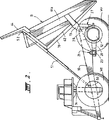
図1は、従来技術に従ったサスペンションシステムの1実施形態を内含するトラックの側面立面図である。
図2は従来技術を示すものであって、トラックボディが持上げられた状態の図1に類似した側面立面図である。
図3は従来技術を示すものであって、後方サスペンションの早期の実施形態の詳細を示しトラックボディ構造を部分的に例示する図1のトラックの後端部立面図である。
図4は従来技術を示すものであって、一方での2つの後方ホイール取付け用ハブのうちの1つの横方向回転の範囲を示すべく一部分が除去された状態の断片的な端部断面立面図である。
図5は従来技術を示すものであって、ボディが除去された状態のトラックフレームの断片時平面図である。
図6は従来技術を示すものであって、一つの後方ホイール取付けとサスペンションの拡大断面側面立面図である。
図7は従来技術を示すものであって、その構造を示すトラックボディの平面図である。
図8は、図1に示されたトラック内のサスペンションシステムに置き換わる本発明のサスペンションシステムの一実施形態の側面立面図である。
図9は、図8に示された実施形態の後方断面図である。
図10は、ボディが除去された状態の図8の実施形態に従ったトラックフレームの断片的平面図である。
図11は、本発明のサスペンションシステムの第2の実施形態の後方断面図である。
図12は、本発明の図8,9及び11のサスペンションシステムを内含する改良型トラック構造の側面図である。
図13は、本発明の第3の実施形態に従ったサスペンションシステムとボディの締結を組込んだ改良型トラック構造の側面図である。
図14は、主フレームに対する連結部のまわりで傾動させられたボディを示す図13の実施形態の側面図である。
図15は、図13のライン15−15に沿った断面図である。
好ましい実施形態の説明
図面のうちの図1〜図5を参照すると、トラックフレームは、後方ホイール取付け用ハブ12及び13をその後方端部近くで懸垂する比較的軽量の長手方向部材対10及び11を含んでいる。長手方向部材10及び11は、以下でさらに詳述する通り、その前方端部において、前方ホイールWf用の前方サスペンション(図示せず)のための取付けを一般に含む取付け用カラーなどの実質的な横断部材14によって、又前面ではバンパー60によって、さらに後方では後方ホイールより前方において後方ホイール取付け用ハブ12及び13のためのサポート手段の一部分を形成する横断部材60aによって連結されている。前方サスペンションは米国特許第5,385,391号により詳細に記述されている形をとることもできるし、又はその他の適当なあらゆる形をしていてもよい。
図3,図4及び図5に示されているように、ホイール取付け用ハブ12及び13は、各々のホイールがハブ12及び13のいずれかの側に1つずつ取付けられている状態でそれ自体後方ホイールWrに連結されている電動牽引モーター16,17,18及び19といったような後方ホイールWrのための駆動手段を支持している。後方ホイールWrの各対の間に後方ホイール取付け用ハブ12及び13が位置設定されていることにより、各ホイールの独立した回転が可能となり、かくして短半径回転によりひき起こされるタイヤの摩耗が回避される。
図1〜6の後方サスペンションシステムには、フレーム部材10及び11にしっかりと固定されたそれ自体横断部材60aに旋回可能に固定された旋回可能取付け部21に締結された中空の前向きに延びる締結部材20を用いて、長手方向フレーム部材10及び11に取付けられた後方ホイール取付け用ハブ12及び13が内含されている。締結部材20及び後方ホイール取付け用ハブ12及び13は、別々に形成されてもよいし又一体式ユニットとして形成されてもよく、中空締結部材20は、ハブ12及び13に締結されたモーター16及び19に冷却用空気を送るように作動する。
各々旋回可能取付け部21には、ハブ12及び13のための2つの回転自由度を与える上部横方向ジャーナル22と下部長手方向ジャーナル23が含まれる。横方向ジャーナル22は、図1及び2に示されているように、或る種の適切な要領で横断部材60aがしっかりと固定されているフレーム部材10及び11の側方プレート10及び11を横断部材60aが貫通できるようにするべくこの領域内で増大した深さをもつものであるフレーム部材10及び11のための後方横断部材60aの一部を成すシャフト24(図5)の端部上のスピンドル区分と係合する。各々の下方ジャーナル23は、締結部材20の端部部分を収容し、このジャーナル23内で、この端部部分は自由に回転し、締結部材20の端部部分は、図面の図6に最も明確に示されているように、締結部材20の端部部分と係合するナット23b及びこの部材上に形成されたフランジ23aによってジャーナル内に拘束されている。
フレーム部材10及び11は同様に、垂直方向にコンプライアンスを有するサスペンション手段又はスプリングユニット27のための取付け用部材26用のジャーナルも同様に提供し、取付け用部材26は同様に、トラックのボディBがそのまわりを旋回しているピボットピン29を収容する一体式に形成されたジャーナル28を有する。スプリングユニット27は、取付け手段26にしっかりと締結されしかも後向き延長部分42により取付け用ハブ12,13に締結されているピストンユニット40を収容するシリンダハウジング41を含んでいる。スプリング効果は、シリンダ内の気体の圧縮又はその他の適切な手段によって得ることができる。
取付け手段26は、ハブ12及び13の横方向回転が制限されるべくフランジ30に密に隣接する位置で各ハブ12,13から延びる突出部分31によって係合されるように適合された下向きに延びる剛性フランジ30を有している。
締結部材20及びそれに連結されたハブ12,13のもう1方の方向への回転は、シリンダの軸に沿って直行するべく、ピストン40に対するその締結及びスプリング手段27のシリンダによるピストン40の封じ込めによって垂直長手方向平面に制限されている。後向き延長部分42に対するピストン40の締結は、ピストン40と後向き延長部分42の間の拘束された球面軸受45による。
後方ホイール取付け用ハブ12及び13のための上述の軸継手及びスプリングユニットによって、ハブ12及び13は、フレーム及びトラックボディBとの関係における各ハブ12,13の動きの柔軟性を容易に増大させるべく長手方向及び横方向の両方の軸を中心として旋回することができるようになる。このような動きの1つが、図面の図4に例示されている。
図8,9及び10に示されている本発明の第1の実施形態においては、後方ホイール取付け用ハブ112,113が、前向きに延びる締結部材120を用いて、長手方向フレーム部材110,111に取付けられた状態で示されている。締結部材120は、それ自体それぞれのフレーム部材110及び111に旋回可能に固定されている旋回可能取付け部121に締結されている。締結部材120及び後方ホイール取付け用ハブ112,113は別々にか又は一体式ユニットとして形成され得る。
各々の旋回可能取付け部121には、フレーム部材110,111に締結されているシャフト124の端部上でスピンドル区分と係合する横方向ジャーナル123が内含されている。後方横断部材160は、シャフト124の内側端部を連結することによって形成される。後方横断部材160の各端部における連結125は剛性継手、ピン継手又は適切なたわみ継手であってよい。
横断部材160は任意であるが、そうでなければ横断部材160が存在しない場合に牽引応力下で増大し少量の「トーアウト(外向)」をひき起こす傾向をもつような締結部材120の端部部分間の一定の離隔距離を維持するのに役立つという点で有用である。横断部材160は同様に、フレーム部材110,111上の牽引応力の下でフレームの長軸のまわりのねじり荷重を減少させる。コーナリングの間、横断部材160は、フレーム部材110,111を横断しての旋回可能取付け部121に対して締結部材120を通して伝達される不等なコーナリング荷重を拡げるイコライザとして作用する。後部横断部材160も同様に、ポンプ、バルブなどといった補助機器を取付けるために有用である。
下部横方向ジャーナル123は、締結部材120の端部部分上で球面軸受123a内に収容される。ジャーナル123は横方向軸及び長手方向軸のまわりのハブの回転を可能にする。
横方向軸のまわりの締結部材120及びそれぞれの連結されたハブ112,113の回転は、垂直方向のコンプライアンスをもつサスペンション手段127によって制限される。サスペンション手段127の下端部129はハブ112,113の長手方向延長部分128と係合する。長手方向延長部分128は好ましくは、車両の長手方向及び横方向軸を中心としたハブの回転を可能にするべくサスペンション手段の下端部129で球面軸受130の中に収容される。球面軸受は同様に、サスペンション手段とハブの間の横方向軸を中心とした制限された相対的回転をも可能にする。
好ましくはシリンダ127a及びピストン150から成るスプリングであるサスペンション手段127は、取付け部材126内にその上端部で収容され、ボルト119で固定される。取付け用部材126は、フレーム部材110及び111のボディピボット131及び端部143と旋回可能に係合する。取付け用部材には、車両の垂直平面に対し垂直でサスペンションピボットを通る1本の軸を中心にして、ボディピボット131、サスペンション手段127及びフレーム部材112,113の間の独立した相対的運動を可能にするサスペンションピボット133を収容するためのヨーク132が具備されている。
サスペンションピボット133は、ヨークの両方のアーム135,136を通って延び内部スリーブ137が中に軸支されている円筒形ブシュ134を内含する。内部スリーブは、円筒形ブシュを超えて延び、ボディピボットアーム138,139内に形成されたアパーチャ内に収容される。内部スリーブ137は、リテーナ140及び保持用ボルト141によって所定の位置に固定される。円筒形ブシュと内部スリーブの間の摩擦力を低減するため、円筒形軸受142を、好ましくは青銅の軸受の形で具備することができる。このようにして、円筒形ブシュ134との関係における内部スリーブ137の動きは、サスペンション手段との関係におけるボディピボットの旋回運動に対応する。
フレーム部材110,111の端部143は、ヨーク132のアーム135,136の間の空間近くの円筒形ブシュの外表面の中心にある球面軸受144を通して円筒形ブシュと係合する。フレーム部材110及び111の端部143はヨークアームの間の空間内に収容され円筒形ブシュ134上にある球面軸受144をとり囲む軸受が具備されている。
円筒形ブシュ134の位置は、サスペンション手段127の取付け用部材126との関係において定められることから、サスペンション手段127とフレーム部材110及び111の間の相対的な動きは、球面軸受144を中心とした相対的運動によって対処される。
それぞれのフレーム部材の端部143がヨーク132内に収容された時点で、フレーム部材端部とヨーク132の間には小さい空隙145,146が存在し、車両の長手方向軸を中心とした取付け部材126の制限された回転を可能にしている。
サスペンション手段の取付け用部材126のヨーク132はボディピボットのアーム138,139の中に収容されることから、地面の平面内で生成された側方荷重は後方アクスルとダンプボディの間で直接伝達され、フレーム部材110,111の長軸を中心とするねじりモーメントは最小限となる。
さらなる改良として、ヨークの垂直軸から垂直方向にコンプライアンスをもつサスペンション手段の垂直軸を側方にオフセットすることによって、ボディ上のねじりモーメントの分布を増強することができると考えられている。
図11及び12においては、サスペンションとボディの旋回可能取付け部233の第2の変形形態が例示されている。サスペンションとボディの旋回可能取付け部のこの実施形態は、図9に示されている取付け部133と置換することができる。
変形実施形態においては、サスペンション取付け用部材126のアーム235,236は、フレーム部材210のいずれかの側に位置づけされ、円筒形シャフト237が両方のアーム及びフレーム部材210の中のアパーチャを通して延びている。円筒形シャフトは、ボディピボットアーム238,239内に形成されたアパーチャの中に収容されリテーナ240及び保持用ボルト241によって所定の位置に固定される。
円筒形シャフト、アーム235,236、フレーム部材210及びボディピボットアーム238,239の間の摩擦力を低減させるため、ブッシング234及び244を具備することもできる。
ブッシング234は、フレーム部材210のアパーチャ内そしてサスペンション取付け用部材126のアーム235及び236の間にはめられる。各ブッシング234は、ジャーナル軸受区分231とスペーサ軸受区分232を提供するように成形することができる。ブッシング234とフレーム部材の間の相対的運動及び付随する摩擦摩耗を防ぐため、スペーサ232とフレーム部材210の突合せ面内の心合せされた之の中に収容されるピン245を用いてフレーム部材210にブッシング234を固定することができる。
ブッシング244は、サスペンション取付け部材126のアーム235及び236中のアパーチャの中にはめられる。ブッシング244は、ジャーナル軸受区分243及びスペーサ又はスラスト軸受区分242を提供するように成形することができる。
図11の配置は、フレーム部材のまわりの取付け用部材236の回転が全く提供されていないことを除いて、図8,9及び10の配置に類似する形で機能する。いくつかの車両構成について、この制約条件は受容可能なものであり得る。この配置は、図9の球面軸受の交換に比べてはるかに単純な構造であり、軸受の交換はより容易で廉価である。
主フレームに対するサスペンションシステムの取付け及びボディ旋回可能取付け部のさらにもう1つの配置が図13,14及び15に示されている。この配置においては、主フレーム310に対する締結部材120の後向き取付けは、図8及び図11の組合せによって示されているものと類似のものである。
サスペンション手段は、サポート126に締結されたスプリングユニット127を内含している。サポート126は、横方向軸を中心としたフレーム部材との関係におけるサスペンション手段の制限された回転を可能にするフレーム部材310に対し旋回可能に連結されている。この旋回可能な連結は、標準的には、横方向−垂直平面内でのサスペンション手段の回転を許さない円筒軸受で構成される。
図15に示されているように、フレーム部材310及びサスペンションサポート126に対するボディ238の旋回可能連結部200,250は、フレーム部材の区分255内にある。ボディ旋回可能連結部200には、ボディピボットアーム238,239の中のアパーチャ内に収容されリテーナ340及び保持用ボルト341によって所定の位置に固定された円筒形シャフト337が含まれている。ボディ旋回可能連結部200のブッシング334は、フレーム部材310の区分255のアパーチャ内にはめ込まれる。各々ブッシング334は、ジャーナル軸受表面331及びスペーサベアリング表面332を提供することができる。
サスペンション部材126の旋回可能連結部250には又、サスペンション部材126内のアパーチャの中に収容されリテーナ360及び保持用ボルト361により所定の位置に固定された円筒形シャフト357も含まれている。ブッシング354はフレーム部材310の区分255内のアパーチャの中で、サスペンション取付け用部材126のアームの間にはめ込まれる。各々のブッシング354は、ジャーナル軸受区分351及びスペーサ軸受区分352を提供することができる。フレーム部材310のブッシング354と区分255の間の相対的運動及び付随する摩擦摩耗を防ぐため、スペーサ区分352と区分255の突合せ表面の中に形成された心合せされた穴の中に収容されているピン355を用いて、スペーサ区分352を区分255に固定する。
サスペンション取付け用部材126のアーム内のアパーチャの中にはめ込まれるようにブッシング342を具備することができる。ブッシング344は、好ましくはジャーナル軸受区分343及びスペーサ又はスラスト軸受区分342を内含している。
この配置のフレーム部材310に対するボディの旋回可能連結部200は、図面に示されている通り、サスペンションシステム取付けから主フレームまでフレーム部材310に沿って後向きに移動させられる。フレーム部材310,311は車両の前方から後方に上向きに勾配がついていてよい。かくして、サスペンションピボットからボディの後方端部251までの距離が同じままであるならば、サスペンションシステム取付け部250から後向きにボディ旋回可能取付け部200を移動させると、後方ホイールからのボディ後方端部の高さh1は、図12に示されているようなボディ旋回可能取付け部とサスペンションシステムの取付け部が一致した時の高さh2より大きい。さらに、ボディ後方端部251からホイールまでの距離は、ボディがもち上げられた時点で増大する。
これは、ピット又はその他の築堤の縁部を表示するのに案内用の土塁が用いられ、ボディを傾けて積載物を落下させる前に、運転手が大型採鉱車両を、後方ホイールが土塁に接触するまで後退させるような、鉱区の状況において特に有利である。
さらに、サスペンション手段は垂直方向にコンプライアンスをもつものとして記述されているものの、出願人は、垂直から車両の後部に向かってサスペンション手段をわずかに傾斜させることが幾分か有利であるということを発見した。このようにして、単にダンプボディ、フレーム及びサスペンションの間の旋回可能連結部を後向き及び上向きに適切な量だけ移動させることによって、図8に示された好ましい実施形態を用いて、ボディが持上げられた位置にある時点での地面より上のダンプボディの後方端部の高さの増大及びダンプボディの後方からボディまでの距離の増大を同時に達成することが可能である。これには、より長いストロークをもつサスペンションユニットのためにより大きなスペースを作るということを含め、数多くの利点がある。フレーム部材110,111と水平の間の角度を増大させることにより、後方アクスルハウジングとフレーム部材の間の相対的な動きに対処するべく後方アクスルの前方区分とフレームの間にはより大きなクリアランスが存在することになる。さらに、図8に示されているダンプボディ、フレーム及びサスペンション手段の間の旋回可能連結部を後向きに移動させることによりそしてかくして後方サスペンションユニットをわずかに後向きに方向転換することにより、後方アクセルエンドキャップ128上に予荷重を加えることが可能であり、これは図8に示されている一般的実施形態に比べていくつかの利点を有する。
ボディピボット200、サスペンション部材ピボット250及びこれら2つのピボットを含む主フレーム255の区分の配置及び強度は、フレーム部材310の前方区分よりもむしろボディピボット238内へサポート126からの横方向ねじり荷重の大部分が伝達されるようなものであることがわかる。このようにして、先行技術の設計に比較して、ねじり力の吸収を増大させることができる。
上述のサスペンションシステムは上述のタイプの又は米国特許第5,385,391号の中に他の形で記述されているタイプのフレームをもつトラックに適しているものの、サスペンションシステムが、上述のものと異なる要領で支持された独立した後方アクスルを有するその他の形態のトラックにも同様に利用可能であるということがわかるはずである。
さらに図面の図1,2,3,4,6を参照すると、特に好ましい実施形態に従ったトラックボディBは、側壁61及び61a、床62、前方壁63及び前方に延びるキャビン保護用延長部分64を含んで成る。トラックボディBは、65〜70で示されているように、床62、前方壁63及び延長部分64の下の主補強ビームがボディから長手方向に延びていることそして前述の通りジャーナル28と係合するピボットピン29を収容するべく形成されたプラケット73の間の1本のラインの近く又はその上にわずか1本の横方向補強用ビーム72があることを含め、数多くの新しい特長を有している。付加的な2本のビーム74,75及び76,77が、図面の図3中に最も明確に示されているように各々の側面61及び61aに沿って延びている。横方向ビーム72は、床62の全幅に延び、好ましくは、図示されている通りボディの側面61,61aを上へ延びている。
米国特許第5476285号中で以前に言及されている通り、従来のトラックボディ設計は、数多くの横方向ビームに依存しており、一般にわずか2本の長手方向ビームがトラックの主フレームより上又はボディ床の側面に沿って走っているだけである。上述の新しいボディ設計の主要な利点としては、ボディ重量の著しい減少及びボディの製造コストの大幅な削減があり、しかもボディはそれが前方及びボディピボットにおいてのみ支持されうるほどの充分な強度をなおももち続け、かくして、米国特許出願第5,385,391号により詳細に記述されているようにトラックの主フレームの重量及びコストを削減することが可能となっている。
上述のことに加えて、床62及び側面61及び61aは、図面の図1,3,4及び7に示されている要領で勾配がついており、かくしてボディBの床62の幅は、図面の図7に最も明確に示されているように、ボディの前方から後方へ増大している。この設計特長がもつ利点は、図2に示されているような傾いた位置までボディがもち上げられた時点で積載物は従来のボディ設計の場合のように一定の幅に制限されるのではなく幅が拡がっていくスペース内に滑り込むことからボディの両側の摩耗が低減されるという点にある。その上、ボディの重量を軽減できて、トラックの全体的幅の増大は全くない。
前出の米国特許第5,385,391号及び5,476,285号に記述されている通りボディは、トラックボディB上の52及び横断部材14に近いフレーム上の取付け点50によって支持された一対の伸張性ラム51によりもち上げられる。
以上でさらに詳述されたトラックボディの特長が、以上でさらに詳述された設計以外の設計のトラックにも同様に利用可能であるということがわかるだろう。
牽引モーター16〜19の締結、前方ホイールアセンブリ、エンジン及びドライバ用キャブを含めたトラック付属部品の構造についての詳細は、これらの事項の各々が比較的標準的な構造のものであり当業者の既存の知識範囲内に入ることから、本仕様書の中には含み入れられなかった。しかしながら、後方アクスルが、両側に1つずつのタイヤを備えた独立した短いアクスルであることに留意されたい。3つの横断部材14,60及び60aが主フレームの2つの主要長手方向部材の間の実質的な強度及び剛性を提供する一方で、フレーム部材10及び11の横方向間隔どりも同様に、旋回可能取付け部73における長手方向フレーム部材に対するボディBの直接的締結によりかなりの程度まで維持される。ボディBの固有強度をこうして利用することにより、フレームの強度、重量及びコストをさらに減少させることが可能となる。Field of Invention
The present invention relates to a suspension system and arrangement for the main structural components of very large trucks of the type used in mining operations.
Background of the Invention
There is considerable commonality between currently available large mining trucks made by different manufacturers, and the following considerations generally apply regardless of the truck manufacturer:
Empty vehicle weight accounts for a high percentage of the maximum total vehicle weight. Typically, the ratio of effective load capacity to empty vehicle weight is only about 1.4: 1. This means that most of the operating costs of such trucks are related to moving the empty vehicle weight rather than the effective load capacity.
Compared to the full width of the truck, the full width of the four rear tires is large. Typically, 65% of the total width of the truck is occupied by four rear tires. For current truck designs, this leads to a very narrow main frame for the truck and very high bending loads on the rear axle and rear wheel support system. The narrow main frame causes a lack of space for maintenance of several components, high stress changes during cornering operations, the need for a rigid rear suspension spring in the vertical direction, and design constraints on the body. It is. The net effect is an increase in weight and cost of the main frame, rear axle, rear wheel support assembly and body.
The distance traveled by the rear suspension system of a truck when fully loaded is very limited compared to the size of the truck. As a standard, the maximum travel distance in the compression direction of the rear axle in relation to the main frame is only about 50 mm when loaded. This limited travel distance is the result of having to achieve adequate roll stiffness from the two spaced narrow rear spring units.
The main frames of these trucks are heavy (for example, 16.5 tons for truck main frames with an effective load rating of 172 tons), are complex welded steel structures that are expensive to design, develop and manufacture and are subject to fatigue cracking It is.
The main load support member (body) of the truck is a very strong and generally rigid member. This strength and stiffness is a result of the need for the body to withstand the impact loads during the loading of large rocks by large excavators.
The body is generally supported by the truck's main frame in a number of ways. For example, at the rear pivot point, two, four, six or eight along the underside of the body, and on some trucks, also at points near the line joining the front wheel center. It is supported by the front extension of the body that contacts the frame. This system supporting a rigid body causes high fluctuations in the stress level in the main frame and body of the truck when the truck passes over uneven ground or when cornering. This feature causes fatigue problems, high design and manufacturing costs, and the need for enormous expenses to limit the bumpy ground on which the truck travels.
The body is tilted (pushed up) by a hydraulic cylinder that reacts against the main frame of the truck at a point near the middle of the front and rear wheels. For this reason, a very large bending load is applied to the main frame of the track, and the main frame needs to be very solid in the middle section. This can also cause large stress changes in the body.
The rear double tire is fixed to rotate together. During short radius turning operations (which occurs frequently in standard mining operations), this causes significant kinking type wear of the tire due to the inner ring differential effect. The relative kinking between the two tires in the double set is believed to have a significant impact on the overall wear of the rear tire on the large mining truck.
The combination of four wide tires on a solid beam type rear axle causes large variations in individual tire loads as the truck crosses uneven ground conditions. This arrangement also means that great care must be taken to match the tire outer diameter and inflation pressure to minimize tire load unevenness over flat ground conditions. is doing.
In general, in currently available truck designs, the transmission of force between the body and the ground is through a very indirect path involving high bending loads in the body, truck main frame, rear axle housing and rear wheel support system. Done. In addition, these bending loads vary greatly when the truck travels over uneven ground, during cornering and when the dump body is lifted during unloading.
A standard very large mining truck is shown in FIG. 1 of the drawing of US Pat. No. 5,385,391, which has a fairly sturdy frame structure that pushes the body up to the frame as shown. The result of the ram being connected and the frame being required to withstand the load supported by the contact between the upper surface of the frame and the body. The large size of the rear axle is also revealed.
Although many track frame design improvements have been proposed over the years, no design has succeeded in addressing problems beyond some of the above outlined. For example, U.S. Pat. No. 3,704,040 Davis et al. Has a very complex arrangement of independent frame members that are described as addressing the numerous problems created by bumpy ground, with the front and rear wheel pairs supported in the middle. Therefore, it discloses a frame arrangement which is expensive and heavy. This patent and related US Pat. No. 3,773,348 also disclose a rear suspension arrangement suitable for use with a centrally supported rear wheel pair. While centrally supported rear wheel pairs offer the potential to overcome some of the inherent problems in currently available large mining trucks, so far this exploits this potential No good method has been established.
In addition to the above, most truck body designs have remained essentially unchanged for many years and are relatively closely spaced laterally assisted by a limited longitudinal beam. Characterized by a very heavy structure reinforced with beams, this results in a very heavy body structure.
Similarly, most conventional track bodies have vertical longitudinal sides and a sloped floor arranged at regular intervals. In one departure from this approach, a body was designed with a vertical side and a flat floor that is wider at the rear than the front of the body. In this arrangement, wear on the sides of the body is reduced, but the flat body floor is not compatible with the main frame design of most trucks, which is the overall width and / or length of the truck. Unless it increases, it will raise the center of gravity of the track.
At least some of the above problems are overcome in the very large vehicles described in US Pat. No. 5,476,285.
Summary and purpose of the invention
It is an object of the present invention to provide a further improved suspension system and configuration for very large vehicles in which at least some of the problems described above are improved.
In one embodiment, the present invention includes a substantially rigid main frame having a front section and a rear section supporting a front wheel, the rear section being substantially securely fastened to the front section; A very large vehicle that includes spaced frames each associated with a wheel mounting hub, each hub independently supporting a pair of rear wheels, one on each side A suspension system for the hub that is pivotally mounted on the frame member to allow limited rotation of the hub about the longitudinal and transverse axes in relation to each frame member. A suspension system is provided comprising forward fastening means and suspension means having substantially vertical compliance.
A suspension means having a substantially vertical compliance is pivotally connected to the hub to allow relative rotation of the hub about a longitudinal axis and a transverse axis in relation to a frame member. Yes. The suspension means is also pivotably connected to the frame member to limit relative rotation of the hub about the lateral axis in relation to the frame member.
In a preferred embodiment, the present invention provides a main frame front section that is relatively narrow and extends between the front wheels, the rear section being wider than the front section, and the spaced frame members are Including an elongated frame portion that progressively extends inwardly from the wider rear section to the narrower front section such that the transition between the front and rear sections is not steep and gradual. It is out.
The front fastening means is preferably pivotably mounted on mounting means extending laterally outward from the frame member, and the main frame is further mounted on the rear frame section by the mounting means for the front fastening means. A transverse member extending between and firmly secured to the spaced frame members to minimize the torsional load imposed on them.
The cross-section preferably comprises a shaft passing through a portion of the frame member with an end portion extending laterally outward from the frame member to provide the attachment means for the forward fastening means.
The forward fastening member may be substantially tubular and the pivotable attachment may have a passage therein for delivering cooling air to an electric traction motor supported by the rear wheel attachment hub.
In another form of the invention, a suspension system as described above, a substantially rigid load bearing body, means for pivotally mounting said body in relation to said main frame, and said rear wheel pair There is provided a heavy vehicle comprising means for maintaining a lateral spacing therebetween. By providing the main reinforcement of the body using a longitudinally extending reinforcing beam, the required body strength can be achieved while significantly reducing the weight and manufacturing costs of the body.
The body is pivotally mounted on the main frame of the truck, which is preferably only supported at the pivot point and at one or two locations near the front of the body, and these front supports are located in front of the truck. Located near the center line of the wheel. The hydraulic cylinder used to tilt the body about its pivot point preferably reacts on the main frame of the truck in one or two places, also near the centerline of the front wheel of the truck. By these means, the body is prevented from exerting a large bending moment in the main longitudinal member of the main frame of the track. The front body support has a positive position between the main frame of the truck and the body, so that the body can provide most of the strength required between the front and rear wheels when in the “down” position. A system may be included.
The use of a rear wheel assembly hub positioned between each pair of wheels is adapted to the use of an electric motor system to drive the rear wheels. The use of such motors easily overcomes the problems associated with solid rear axles, thus reducing the weight of the rear wheel support system, improving the load sharing between the rear tires, and the rear tire wear effect of such axles. Has the inherent advantage that can be reduced. However, acceptable results can also be obtained using a mechanical drive system. Rear wheel mounting to tilt one or both of the wheels mounted on the hub at a non-vertical angle to improve vehicle stability during cornering operations and when operating at a cross (lateral) slope Arrangement can also be utilized. Positioning the rear wheel mounting hub between each wheel pair allows each wheel to rotate independently, thus avoiding tire wear caused by short radius rotation.
In another form of the invention, a substantially rigid main frame having a front section and a rear section for supporting a front wheel, the rear section being securely fastened to the front section, each for wheel mounting. It is a large vehicle that includes spaced frame members associated with hubs, each hub independently supporting a pair of rear wheels, one on each side, and including a suspension system. The
The suspension system is pivotally attached to the frame member to allow limited rotation about the longitudinal and transverse axes in relation to each frame member and vertically compliant suspension means. Forward fastening means for the hub,
A lateral spacing between a substantially rigid load bearing body, means for pivotally mounting the body in relation to the main frame in the vicinity of the pivotable mounting of the suspension means relative to the frame means and the rear wheel There is provided a large vehicle further comprising means for maintaining the above.
A vertically compliant suspension means is pivotally fastened to the hub to allow limited relative rotation of the hub about the longitudinal and transverse axes in relation to the frame member. ing. The suspension means is likewise pivotally connected to the frame member to allow relative rotation of the hub about the transverse axis in relation to the frame member.
The suspension means preferably includes a suspension support member that is mounted for pivotal movement on the frame member. In one preferred form, the suspension support attachment is close to or coincident with the pivotable attachment of the body to the main frame.
In a preferred form of the invention, the pivotable connection of the suspension means to the frame member allows the suspension means to rotate only about an axis parallel to the body pivot axis. The body pivot can include a cylindrical bearing that engages the frame member and the support of the suspension means.
In an alternative embodiment of the invention, the pivotable connection of the suspension means to the frame member or the pivotable connection of the frame member itself is limited rotation of the hub in the lateral-vertical plane in relation to the frame member. Enable. The suspension support of the suspension means may be provided with a yoke for supporting a spherical bearing that engages a bearing surface formed in each frame member. The body support on the yoke Swivel mount (body pivot) A transversely extending bush may be provided with an internal sleeve for pivoting therein.
At the time of substitution, body support Swivel mount Can provide support for spherical bearings, said bearings engaging a bearing surface formed in each frame member and forward for a spherical bearing housing on the frame member and a hub on the frame member The torsional load of the frame member between the fastening means is removed.
The pivoting attachment of the suspension means and body allows the main frame, body support and suspension means to pivot independently of the other two. The side loads thus created in the tire / road interface can be transmitted directly into the dump body support, substantially bypassing the frame.
In addition to substantially direct transmission of dump body load onto the suspension means, for devices such as anti-sway bars, Panard rods or similar devices for transmitting cornering load between the rear axle and the dump body There is no need.
The forward fastening means is preferably pivotally mounted on a mounting arm mounted on mounting means extending laterally outward from the frame member, the mounting means being centered about the transverse and longitudinal axes. The mounting arm can be turned.
While having a body swivel mounting that matches the swivel mounting of the suspension means has many advantages, in some cases, the swivel mounting of the body moved a short distance from the swivel mounting of the suspension means It is preferable to have a part. In that case, a short intervention section of the main frame is used to transmit the lateral load between the dump body and the suspension means.
Accordingly, the pivotable attachment of the body to the frame member may be spaced from the pivotable attachment of the suspension means to the frame member, preferably rearward and / or from the pivotable attachment of the suspension means to the frame member. It is spaced upwards.
[Brief description of the drawings]
The foregoing and other features, objects and advantages of the present invention will become more apparent from the following description of preferred embodiments and the accompanying drawings. In the drawing,
FIG. Conventional technology 1 is a side elevation view of a truck including an embodiment of a suspension system according to FIG.
Figure 2 Showing the prior art FIG. 2 is a side elevational view similar to FIG. 1 with the track body lifted.
Figure 3 Showing the prior art FIG. 2 is a rear end elevation view of the track of FIG. 1 showing details of an early embodiment of the rear suspension and partially illustrating the track body structure.
Figure 4 Showing the prior art FIG. 6 is a fragmentary end elevational view with a portion removed to show the range of lateral rotation of one of the two rear wheel mounting hubs on the one hand.
FIG. Showing the prior art FIG. 5 is a fragmentary plan view of the track frame with the body removed.
FIG. Showing the prior art FIG. 3 is an enlarged cross-sectional side elevational view of one rear wheel attachment and suspension.
FIG. Showing the prior art FIG. 2 is a plan view of a track body showing its structure.
FIG. 8 is a side elevation view of one embodiment of the suspension system of the present invention that replaces the suspension system in the truck shown in FIG.
FIG. 9 is a rear cross-sectional view of the embodiment shown in FIG.
FIG. 10 is a fragmentary plan view of a track frame according to the embodiment of FIG. 8 with the body removed.
FIG. 11 is a rear sectional view of the second embodiment of the suspension system of the present invention.
12 is a side view of an improved track structure including the suspension system of FIGS. 8, 9 and 11 of the present invention.
FIG. 13 is a side view of an improved track structure incorporating a suspension system and body fastening according to a third embodiment of the present invention.
FIG. 14 is a side view of the embodiment of FIG. 13 showing the body tilted about a connection to the main frame.
FIG. 15 is a cross-sectional view taken along line 15-15 in FIG.
DESCRIPTION OF PREFERRED EMBODIMENTS
Referring to FIGS. 1-5 of the drawings, the track frame includes a pair of relatively lightweight
As shown in FIGS. 3, 4 and 5, the
The rear suspension system of FIGS. 1-6 includes a hollow, forwardly extending fastening member fastened to a
Each
The
Mounting means 26 is a downwardly extending rigid flange adapted to be engaged by a protruding
The rotation of the
With the above-described shaft coupling and spring unit for the rear
In the first embodiment of the invention shown in FIGS. 8, 9 and 10, the rear
Each pivotable mounting 121 includes a
The
The lower
The rotation of the
The suspension means 127, which is preferably a spring composed of a
The
The ends 143 of the
Since the position of the
When the
Since the
As a further improvement, it is believed that the torsional moment distribution on the body can be enhanced by laterally offsetting the vertical axis of the suspension means that is vertically compliant from the vertical axis of the yoke.
11 and 12, a second variant of the suspension and body
In an alternative embodiment, the
In order to reduce the frictional force between the cylindrical shaft,
The
The
The arrangement of FIG. Around the frame
Still another arrangement of the suspension system attachment and body pivotable attachment to the main frame is shown in FIGS. In this arrangement, the rearward attachment of the
The suspension means includes a
As shown in FIG. 15, the
The
A
The
This is because a guide earth is used to display the pit or other embankment edge, before the driver tilts the body and drops the load, the driver is the large mining vehicle and the rear wheel is the earth. This is particularly advantageous in a mining situation where it is retracted until it touches.
Further, although the suspension means is described as being vertically compliant, the applicant has found that it is somewhat advantageous to slightly tilt the suspension means from the vertical toward the rear of the vehicle. did. In this way, the body is lifted using the preferred embodiment shown in FIG. 8 simply by moving the pivotable connection between the dump body, frame and suspension back and upward by an appropriate amount. It is possible to simultaneously increase the height of the rear end of the dump body above the ground and increase the distance from the rear of the dump body to the body at a certain point. This has a number of advantages, including making more space for suspension units with longer strokes. By increasing the angle between the
The arrangement and strength of the
While the suspension system described above is suitable for trucks having a frame of the type described above or otherwise described in US Pat. No. 5,385,391, the suspension system is supported in a manner different from that described above. It should be understood that other forms of trucks having separate rear axles can be used as well.
Still referring to FIGS. 1, 2, 3, 4, and 6 of the drawings, the truck body B according to a particularly preferred embodiment comprises a
As previously mentioned in US Pat. No. 5,476,285, the conventional track body design relies on a number of transverse beams, generally only two longitudinal beams are above the main frame of the track or on the body It just runs along the side of the floor. The main advantages of the new body design described above are a significant reduction in body weight and a significant reduction in body manufacturing costs, yet the body is still strong enough that it can only be supported at the front and body pivot. It is thus possible to reduce the weight and cost of the main frame of the truck as described in more detail in US Pat. No. 5,385,391.
In addition to the above, the
As described in the aforementioned US Pat. Nos. 5,385,391 and 5,476,285, the body has a pair of
It will be appreciated that the features of the truck body further detailed above are equally applicable to trucks of designs other than those further detailed above.
Details of the structure of the truck attachments, including the fastening of the traction motors 16-19, the front wheel assembly, the engine and the driver's cab, are those of a relatively standard structure, It was not included in this specification because it was within the knowledge range of. However, it should be noted that the rear axle is an independent short axle with one tire on each side. The three
Claims (16)
該サスペンションシステムは、各フレーム部材との関係における長手方向及び横方向軸を中心とした前記ハブの制限された回転を可能にするような前記フレーム部材上に旋回可能に取りつけられた各ハブ用の前方締結手段と、実質的に垂直方向のコンプライアンスをもつサスペンションスプリングユニット(127)とを具備し、
各々の実質的に垂直方向のコンプライアンスをもつサスペンションスプリングユニット(127)は各フレーム部材(110、111)との関係における長手方向軸及び横方向軸を中心とした前記ハブ(112、113)の回転を可能にするように前記ハブに旋回可能に取り付けられ、
各々の実質的に垂直方向のコンプライアンスをもつサスペンションスプリングユニット(127)はまた、旋回可能取付け部(133、233)を具備するサスペンション支持部材(126)によって上記フレーム部材(110、111)に旋回可能に取り付けられ、上記旋回可能取付け部(133、233)は、上記実質的に垂直方向のコンプライアンスをもつサスペンションスプリングユニット(127)の回転を、ボディピボット(131)の軸に対して平行な軸のまわりの回転のみに制限し、それによって上記フレーム部材に対して上記ハブの横向きの移動を防止する、サスペンションシステム。Suspension system for a very large vehicle, wherein the very large vehicle includes a substantially rigid main frame having a front section supporting a front wheel and a rear section, the rear section Includes spaced frame members (110 , 111 , 210, 310 ) that are substantially securely fastened to the forward section and each associated with a wheel mounting hub (112, 113). In the suspension system for a very large vehicle, the hub independently supports a pair of rear wheels on each side and a body pivotally mounted on the main frame.
The suspension system is for each hub pivotally mounted on the frame member to allow limited rotation of the hub about the longitudinal and transverse axes in relation to each frame member. A forward fastening means and a suspension spring unit (127) having a substantially vertical compliance;
Each substantially vertical compliance suspension spring unit (127) rotates the hub (112, 113) about the longitudinal and lateral axes in relation to each frame member (110, 111). Pivotally attached to the hub to allow
Each substantially vertical compliance suspension spring unit (127) is also pivotable to the frame member (110, 111) by a suspension support member (126) with pivotable attachments (133 , 233 ). And the pivotable attachments (133 , 233 ) allow rotation of the substantially vertical compliance suspension spring unit (127) to rotate in an axis parallel to the axis of the body pivot (131) . A suspension system that is limited to rotation only , thereby preventing lateral movement of the hub relative to the frame member.
上記フレーム部材との関係において長手方向及び横方向軸を中心とした制限された回転を可能にするような前記フレーム部材(110、111、210、310)に対し旋回可能に取付けられた各ハブ用の前方締結手段と、実質的に垂直方向のコンプライアンスをもつサスペンションスプリングユニット(127)とを含むサスペンションシステムと、を含んで成る大型車両であって、For each hub pivotably attached to the frame member (110, 111, 210, 310) that allows limited rotation about the longitudinal and lateral axes in relation to the frame member. A suspension system comprising a front fastening means and a suspension spring unit (127) having a substantially vertical compliance,
実質的に剛性の荷重支持ボディ(B)と、前記フレーム部材に対する上記実質的に垂直方向のコンプライアンスをもつサスペンションスプリングユニット(127)の旋回可能取付け部の近くで前記主フレームとの関係において前記ボディを旋回可能に取付けるための手段(131)と、前記後方ホイールの間に横方向間隔を維持するための手段とをさらに含み、The body in relation to the main frame in the vicinity of a substantially rigid load bearing body (B) and a pivotable mounting portion of the suspension spring unit (127) having a substantially vertical compliance to the frame member. Means for pivotally mounting the vehicle and means for maintaining a lateral spacing between the rear wheels,
上記実質的に垂直方向のコンプライアンスをもつサスペンションスプリングユニットは各フレーム部材との関係における長手方向及び横方向軸を中心とした前記ハブの制限された回転を可能にするように前記ハブに旋回可能に締結され、The substantially vertical compliance suspension spring unit is pivotable to the hub to allow limited rotation of the hub about the longitudinal and lateral axes in relation to each frame member. Concluded,
上記実質的に垂直方向のコンプライアンスをもつサスペンションスプリングユニット(127)はまた、サスペンションピボット(133、233)を具備するサスペンション支持部材(126)によって上記フレーム部材(110、111)に旋回可能に接続され、上記サスペンションピボット(133、233)は、上記実質的に垂直方向のコンプライアンスをもつサスペンションスプリングユニットの回転を、ボディピボット(131)の軸に対し平行な軸のまわりの回転のみに制限し、それによって上記フレーム部材に対して上記ハブの横向きの移動を防止する、大型車両。The suspension spring unit (127) having substantially vertical compliance is also pivotally connected to the frame member (110, 111) by a suspension support member (126) having a suspension pivot (133, 233). The suspension pivot (133, 233) restricts the rotation of the suspension spring unit having a substantially vertical compliance to rotation around an axis parallel to the axis of the body pivot (131). A large vehicle that prevents lateral movement of the hub relative to the frame member.
Applications Claiming Priority (3)
| Application Number | Priority Date | Filing Date | Title |
|---|---|---|---|
| US41461995A | 1995-03-31 | 1995-03-31 | |
| US08/414,619 | 1995-03-31 | ||
| PCT/AU1996/000180 WO1996030223A1 (en) | 1995-03-31 | 1996-03-29 | Large dump truck suspension |
Publications (2)
| Publication Number | Publication Date |
|---|---|
| JPH11502481A JPH11502481A (en) | 1999-03-02 |
| JP3847785B2 true JP3847785B2 (en) | 2006-11-22 |
Family
ID=23642217
Family Applications (1)
| Application Number | Title | Priority Date | Filing Date |
|---|---|---|---|
| JP52871396A Expired - Fee Related JP3847785B2 (en) | 1995-03-31 | 1996-03-29 | Large dump truck suspension |
Country Status (10)
| Country | Link |
|---|---|
| US (1) | US6086076A (en) |
| EP (1) | EP0814964B1 (en) |
| JP (1) | JP3847785B2 (en) |
| CN (1) | CN1060119C (en) |
| BR (1) | BR9607876A (en) |
| DE (1) | DE69624802T2 (en) |
| ES (1) | ES2186773T3 (en) |
| RU (1) | RU2218280C2 (en) |
| WO (1) | WO1996030223A1 (en) |
| ZA (1) | ZA962542B (en) |
Families Citing this family (33)
| Publication number | Priority date | Publication date | Assignee | Title |
|---|---|---|---|---|
| US6408970B1 (en) | 2000-08-28 | 2002-06-25 | Allen L. Eng | Cab suspension system for terminal tractors |
| DE20206821U1 (en) * | 2002-04-29 | 2003-09-11 | Liebherr Werk Biberach Gmbh | Travel drive for trucks |
| US6783187B2 (en) * | 2002-10-29 | 2004-08-31 | Michael S. Parsons | Vector neutral truck |
| US20050093260A1 (en) * | 2003-10-30 | 2005-05-05 | Trescott William B. | Non co-planar rear suspension for heavy trucks |
| DE10351308A1 (en) * | 2003-10-31 | 2005-06-23 | Deere & Company, Moline | Vehicle axle system, torque tube, vehicle axle and vehicle |
| US7144022B2 (en) * | 2004-08-19 | 2006-12-05 | Cnh America Llc | Tractor suspension system |
| DE202007004178U1 (en) | 2007-02-16 | 2008-06-26 | Liebherr-Werk Biberach Gmbh | Axle suspension for heavy vehicles |
| US7780241B2 (en) * | 2007-06-12 | 2010-08-24 | Caterpillar Inc | Two-piece expandable thrust washer and machine using same |
| DE102007054522A1 (en) | 2007-11-06 | 2009-05-07 | Thomas Sauer | Material transporting process for mines, quarries etc. involves altering direction of dump truck independently of truck itself |
| DE102008036914A1 (en) | 2008-08-01 | 2010-02-04 | Thomas Sauer | Rear suspension for heavy dumpers, has rigid vehicle frame and front vehicle segment with steerable front wheels, and rear frame segment with non-steerable rear wheels |
| DE102009026739A1 (en) | 2009-06-04 | 2010-12-09 | Zf Friedrichshafen Ag | Joint and / or bearing arrangement with an elastic intermediate layer |
| JP5236810B2 (en) | 2009-06-17 | 2013-07-17 | 株式会社小松製作所 | Dump truck |
| WO2011036274A1 (en) * | 2009-09-24 | 2011-03-31 | Technology Investments Limited | A suspension system |
| SE534575C2 (en) | 2010-02-19 | 2011-10-11 | Atlas Copco Rock Drills Ab | Method and device for loading vehicles for tipping a load basket |
| US20130069416A1 (en) * | 2010-06-03 | 2013-03-21 | Hitachi Construction Machinery Co., Ltd. | Dump Truck |
| DE102011102101A1 (en) * | 2011-05-20 | 2012-11-22 | GM Global Technology Operations LLC (n. d. Gesetzen des Staates Delaware) | Storage for use in four-steering wheel rear axle of motor car for storing e.g. wheel carrier, has inner and/or outer bushes provided with sleeves, where outer bush is arranged such that outer and inner bushes have common longitudinal axis |
| AU2011378342B2 (en) * | 2011-09-29 | 2015-11-26 | Hitachi Construction Machinery Co., Ltd. | Body structure for dump truck |
| CN102815179B (en) * | 2012-09-04 | 2016-01-20 | 航天重型工程装备有限公司 | A kind of single trailing arm type independent suspension with hydro-pneumatic spring |
| DE102014001307A1 (en) | 2014-01-31 | 2015-08-06 | GM Global Technology Operations LLC (n. d. Gesetzen des Staates Delaware) | Suspension, Radaufhängungslageranordnung and motor vehicle |
| CA2940603C (en) * | 2014-02-27 | 2017-09-12 | Komatsu Ltd. | Dump truck |
| CA2940600C (en) * | 2014-02-27 | 2017-12-19 | Komatsu Ltd. | Dump truck |
| JP6469647B2 (en) * | 2014-02-27 | 2019-02-13 | 株式会社小松製作所 | Dump truck |
| FR3019135B1 (en) * | 2014-03-27 | 2016-03-11 | Renault Sas | "MOTOR VEHICLE HAVING TRAINING FIXING GUIDE MEANS" |
| CN104827947A (en) * | 2014-10-16 | 2015-08-12 | 诸城福田汽车科技开发有限公司 | Cargo carrying structure of dump truck and dump truck with same |
| JP6218047B2 (en) * | 2015-02-05 | 2017-10-25 | 日立建機株式会社 | Dump truck |
| AU2015203753A1 (en) * | 2015-07-06 | 2017-02-02 | AL-KO Chassis Systems Pty Ltd | A Suspension Assembly |
| CA2994628C (en) | 2016-03-16 | 2019-08-20 | Komatsu Ltd. | Dump truck dump body, and dump truck |
| CN107539192B (en) * | 2016-06-29 | 2019-08-13 | 比亚迪股份有限公司 | A kind of electronic mine dumper |
| CN109963742A (en) * | 2016-08-25 | 2019-07-02 | 沃尔沃建筑设备公司 | Engineering machinery |
| DE102017218682B4 (en) * | 2017-10-19 | 2021-05-06 | Ford Global Technologies, Llc | Longitudinal leaf spring device with stop buffer unit |
| US11186315B2 (en) * | 2019-10-25 | 2021-11-30 | Caterpillar Inc. | Space frame front upper frame connection |
| US11498470B2 (en) * | 2019-10-25 | 2022-11-15 | Caterpillar Inc. | Rocker support assembly |
| IT201900020082A1 (en) * | 2019-10-30 | 2021-04-30 | Ces S R L | AXLE UNIT FOR SELF-PROPELLED OPERATING MACHINE |
Family Cites Families (11)
| Publication number | Priority date | Publication date | Assignee | Title |
|---|---|---|---|---|
| US2862724A (en) * | 1955-05-23 | 1958-12-02 | Eisenhauer Mfg Company | By-pass arrangement for vehicle suspension |
| DE1755126C3 (en) * | 1968-04-02 | 1980-01-10 | Hermann Dr.-Ing. 2000 Norderstedt Klaue | Wheel suspension for a truck with a tiltable container |
| US3552798A (en) * | 1969-02-03 | 1971-01-05 | Caterpillar Tractor Co | Dump truck body supporting means |
| US3704040A (en) * | 1970-08-28 | 1972-11-28 | Peerless Mfg Co | Vehicle for traversing rough terrain |
| US3940163A (en) * | 1970-08-28 | 1976-02-24 | Marion Power Shovel Company, Inc. | Vehicle for traversing rough terrain |
| US3773348A (en) * | 1972-05-08 | 1973-11-20 | Peerless Mfg Co | Vehicle suspension assembly |
| US3840244A (en) * | 1973-11-19 | 1974-10-08 | Caterpillar Tractor Co | Haul unit suspension system |
| US4049071A (en) * | 1976-03-08 | 1977-09-20 | Caterpillar Tractor Co. | Modular dual wheel suspension and drive arrangement for trucks |
| DE3434297A1 (en) * | 1984-09-19 | 1986-03-27 | Karl Matthias 8951 Ruderatshofen Mayer | Parallel swing four-wheel axle for vehicles |
| ZA901615B (en) * | 1989-03-03 | 1990-12-28 | Broken Hill Pty Co Ltd | Large truck |
| ES2179153T3 (en) * | 1990-09-03 | 2003-01-16 | Bhp Au Coal Pty Ltd | SUSPENSION AND BODY SYSTEM FOR LARGE VEHICLES WITH TICKETS. |
-
1996
- 1996-03-29 ES ES96907217T patent/ES2186773T3/en not_active Expired - Lifetime
- 1996-03-29 DE DE69624802T patent/DE69624802T2/en not_active Expired - Lifetime
- 1996-03-29 BR BR9607876-6A patent/BR9607876A/en not_active IP Right Cessation
- 1996-03-29 EP EP96907217A patent/EP0814964B1/en not_active Expired - Lifetime
- 1996-03-29 CN CN96194046A patent/CN1060119C/en not_active Expired - Fee Related
- 1996-03-29 RU RU97118130/11A patent/RU2218280C2/en not_active IP Right Cessation
- 1996-03-29 WO PCT/AU1996/000180 patent/WO1996030223A1/en active IP Right Grant
- 1996-03-29 JP JP52871396A patent/JP3847785B2/en not_active Expired - Fee Related
- 1996-03-29 ZA ZA962542A patent/ZA962542B/en unknown
- 1996-03-29 US US08/836,322 patent/US6086076A/en not_active Expired - Lifetime
Also Published As
| Publication number | Publication date |
|---|---|
| BR9607876A (en) | 1999-11-30 |
| ES2186773T3 (en) | 2003-05-16 |
| ZA962542B (en) | 1996-11-18 |
| CN1185132A (en) | 1998-06-17 |
| RU2218280C2 (en) | 2003-12-10 |
| EP0814964A1 (en) | 1998-01-07 |
| WO1996030223A1 (en) | 1996-10-03 |
| EP0814964A4 (en) | 2001-01-17 |
| JPH11502481A (en) | 1999-03-02 |
| US6086076A (en) | 2000-07-11 |
| DE69624802T2 (en) | 2003-06-18 |
| CN1060119C (en) | 2001-01-03 |
| EP0814964B1 (en) | 2002-11-13 |
| DE69624802D1 (en) | 2002-12-19 |
Similar Documents
| Publication | Publication Date | Title |
|---|---|---|
| JP3847785B2 (en) | Large dump truck suspension | |
| JP3300345B2 (en) | Heavy vehicles and load carrying bodies for heavy vehicles | |
| US20040036245A1 (en) | Suspension system and body for large dump trucks | |
| US5820150A (en) | Independent suspensions for lowering height of vehicle frame | |
| US5538274A (en) | Modular Independent coil spring suspension | |
| CA2247324C (en) | Linkage suspension system | |
| JP2908015B2 (en) | Large dump truck | |
| RU2487018C2 (en) | Stabiliser system for wheel axle suspension, and stabiliser | |
| US10407114B2 (en) | Attachment device for track support beam of tracked vehicle | |
| US5163700A (en) | Dual rear axle assembly for large vehicles | |
| EP0706904B1 (en) | Improvements in independent suspensions | |
| US20050093260A1 (en) | Non co-planar rear suspension for heavy trucks | |
| CA2216541C (en) | Large dump truck suspension | |
| AU717749B2 (en) | Large dump truck suspension | |
| CN213676287U (en) | Fixing device, front axle suspension device and dumper | |
| AU663469B2 (en) | Suspension system and body for large dump trucks | |
| CN116080762A (en) | Vehicle chassis and mining dump truck | |
| US20040135335A1 (en) | Device for hitching a direct-link vehicle to the wheel axles and truck tractor equipped with the same |
Legal Events
| Date | Code | Title | Description |
|---|---|---|---|
| A131 | Notification of reasons for refusal |
Free format text: JAPANESE INTERMEDIATE CODE: A131 Effective date: 20050426 |
|
| A601 | Written request for extension of time |
Free format text: JAPANESE INTERMEDIATE CODE: A601 Effective date: 20050725 |
|
| A602 | Written permission of extension of time |
Free format text: JAPANESE INTERMEDIATE CODE: A602 Effective date: 20050829 |
|
| A521 | Request for written amendment filed |
Free format text: JAPANESE INTERMEDIATE CODE: A523 Effective date: 20050831 |
|
| A131 | Notification of reasons for refusal |
Free format text: JAPANESE INTERMEDIATE CODE: A131 Effective date: 20051129 |
|
| A601 | Written request for extension of time |
Free format text: JAPANESE INTERMEDIATE CODE: A601 Effective date: 20060227 |
|
| A602 | Written permission of extension of time |
Free format text: JAPANESE INTERMEDIATE CODE: A602 Effective date: 20060424 |
|
| A521 | Request for written amendment filed |
Free format text: JAPANESE INTERMEDIATE CODE: A523 Effective date: 20060529 |
|
| TRDD | Decision of grant or rejection written | ||
| A01 | Written decision to grant a patent or to grant a registration (utility model) |
Free format text: JAPANESE INTERMEDIATE CODE: A01 Effective date: 20060725 |
|
| A61 | First payment of annual fees (during grant procedure) |
Free format text: JAPANESE INTERMEDIATE CODE: A61 Effective date: 20060824 |
|
| R150 | Certificate of patent or registration of utility model |
Free format text: JAPANESE INTERMEDIATE CODE: R150 |
|
| FPAY | Renewal fee payment (event date is renewal date of database) |
Free format text: PAYMENT UNTIL: 20100901 Year of fee payment: 4 |
|
| FPAY | Renewal fee payment (event date is renewal date of database) |
Free format text: PAYMENT UNTIL: 20110901 Year of fee payment: 5 |
|
| FPAY | Renewal fee payment (event date is renewal date of database) |
Free format text: PAYMENT UNTIL: 20120901 Year of fee payment: 6 |
|
| FPAY | Renewal fee payment (event date is renewal date of database) |
Free format text: PAYMENT UNTIL: 20130901 Year of fee payment: 7 |
|
| R250 | Receipt of annual fees |
Free format text: JAPANESE INTERMEDIATE CODE: R250 |
|
| R250 | Receipt of annual fees |
Free format text: JAPANESE INTERMEDIATE CODE: R250 |
|
| LAPS | Cancellation because of no payment of annual fees |