JP3842670B2 - Foldable electronic device - Google Patents
Foldable electronic device Download PDFInfo
- Publication number
- JP3842670B2 JP3842670B2 JP2002050126A JP2002050126A JP3842670B2 JP 3842670 B2 JP3842670 B2 JP 3842670B2 JP 2002050126 A JP2002050126 A JP 2002050126A JP 2002050126 A JP2002050126 A JP 2002050126A JP 3842670 B2 JP3842670 B2 JP 3842670B2
- Authority
- JP
- Japan
- Prior art keywords
- housing
- tube
- belt
- portions
- flexible substrate
- Prior art date
- Legal status (The legal status is an assumption and is not a legal conclusion. Google has not performed a legal analysis and makes no representation as to the accuracy of the status listed.)
- Expired - Fee Related
Links
Images


Description
【0001】
【発明の属する技術分野】
この発明は、例えば折り畳み構造をなす携帯電話機や携帯情報端末に代表される折り畳み型電子機器に関する。
【0002】
【従来の技術】
従来、折り畳み型の携帯電話機は、例えば受話用スピーカおよび表示器等が設けられる第1の筐体と、送話用マイクロホンおよびキーパッド等が設けられる第2の筐体とを、ヒンジを介して回動自在に接続するように構成されている。この種の携帯電話機は、待ち受け時には筐体を折り畳んで小型化することで良好な携帯性が得られ、また通信時には筐体を展開することで高い操作性と視認性を確保できる利点がある。
【0003】
ところで、この種の携帯電話機では、第1の筐体内に実装された回路と第2の筐体内に実装された回路との間を、ヒンジを介して電気的に接続する必要があり、この接続をフレキシブル基板を用いて行っている。
【0004】
図8は、本出願人が特願2001-171599号として出願済みの折り畳み型電子機器の要部構成をその接続手順とともに示す斜視図である。
【0005】
フレキシブル基板40は、第1の帯状部41と第2の帯状部42とを中間部43によりクランク状に一体に接続したものであり、基板の片面あるいは両面には複数本の配線パターンが形成されている。第1および第2の帯状部41,42の先端部にはそれぞれコネクタ45,46が取着してある。
【0006】
このフレキシブル基板40は、中間部43を、図8(a)に示す谷折り位置B−Bを中心にV字型に折り曲げ、同図(b)に示す状態とする。続いて、上記V字型に折り曲げられた中間部43を軸として、第1および第2の帯状部41,42をそれぞれ図中C,Cに示すように互いに反対となる方向に巻き回すことで、独立した第1および第2のロール状緩衝部を形成する。そしてこのロール状緩衝部を、図8(c)のDに示すように筒状をなすヒンジ部30の空洞内に収容する。第1および第2の帯状部41,42の先端部をそれぞれ、ヒンジ部30に形成された開口部を通して第1および第2の筐体10,20内に導き入れ、コネクタ45,46をそれぞれ、図8(d)に示すように、第1および第2の筐体10,20内に実装されている回路13,23のコネクタ51,52に接続する。
【0007】
【発明が解決しようとする課題】
ところが、携帯電話機などでは高度な機能を実現するために、2つの筐体の間で授受すべき信号線数が非常に多い。このため、このような多数の信号線を収容するためにフレキシブル基板40の幅も大きくなっている。
【0008】
フレキシブル基板40は巻き回されるのであるが、中間部43は巻き回しの方向が幅方向となっている。このため、外径が小さくなるように巻き回すことが困難である。中間部43は中心部に位置することになるため、その外径が大きくなることでロール状緩衝部の外径も大きくなってしまう。
【0009】
ロール状緩衝部の外径が大きくなると、ヒンジ部30を大型化しなければならず、折り畳み型電子機器全体のサイズが増大してしまう。また、折り畳み動作に伴って、フレキシブル基板40がケース内壁にこすれ易くなるため、フレキシブル基板40が劣化し易くなってしまう恐れがあった。
【0010】
本発明はこのような事情を考慮してなされたものであり、その目的とするところは、フレキシブル基板を巻き回してなるロール状緩衝部の外径を小さく抑え、これにより機器の小型化および機器の信頼性の向上を図った折り畳み型電子機器を提供することにある。
【0011】
【課題を解決するための手段】
以上の目的を達成するために第1の本発明は、第1の筐体と第2の筐体とを、これらの筐体内間を連通する開口部を備えたヒンジ部により回動自在に連結してなる折り畳み型電子機器において、前記第1の筐体内に収容される第1の回路と前記第2の筐体内に収容される第2の回路との間を接続するフレキシブル基板と、長手方向に沿ってスリットが形成されたチューブとを具備し、前記フレキシブル基板は、第1および第2の帯状部とこれらの帯状部をクランク状に接続する中間部とを一体に形成してなり、前記中間部を前記チューブの内部空間に収容するとともに、前記第1および第2の帯状部を前記スリットを通して前記チューブの外側へとそれぞれ引出し、前記第1および第2の帯状部を前記チューブの外面に巻き付けた上で、前記第1および第2の帯状部の先端を前記開口部を通してそれぞれ第1および第2の筐体内に延在させて前記第1および第2の回路に接続した。
また前記の目的を達成するために第2の本発明は、第1の筐体と第2の筐体とを、これらの筐体内間を連通する開口部を備えたヒンジ部により回動自在に連結してなる折り畳み型電子機器において、前記第1の筐体内に収容される第1の回路と前記第2の筐体内に収容される第2の回路との間を接続するフレキシブル基板と、長手方向に沿ってスリットが形成されたチューブとを具備し、前記フレキシブル基板は、前記ヒンジ部に収容される中間部とこの中間部と接続し前記開口部を通る第1および第2の帯状部とを一体に形成してなり、前記中間部を前記チューブの内部空間に収容するとともに、前記第1および第2の帯状部を前記チューブの外面に巻き付けた上でそれぞれ第1および第2の筐体内に延在させて前記第1および第2の回路に接続した。
また前記の目的を達成するために第3の本発明は、第1の筐体と第2の筐体とを、これらの筐体内間を連通する開口部を備えたヒンジ部により回動自在に連結してなる折り畳み型電子機器において、前記第1の筐体内に収容される第1の回路と前記第2の筐体内に収容される第2の回路との間を接続するフレキシブル基板と、長手方向に沿ってスリットが形成されたチューブと、前記第1の筐体と前記第2の筐体との間に配線されるケーブルとを具備し、前記フレキシブル基板は、第1および第2の帯状部とこれらの帯状部をクランク状に接続する中間部とを一体に形成してなり、前記中間部を前記チューブの内部空間に収容するとともに、前記第1および第2の帯状部を前記スリットを通して前記チューブの外側へとそれぞれ引出し、前記第1および第2の帯状部の先端を前記開口部を通してそれぞれ第1および第2の筐体内に延在させて前記第1および第2の回路に接続し、さらに前記チューブに前記ケーブルを挿通させた。
また前記の目的を達成するために第4の本発明は、第1の筐体と第2の筐体とを、これらの筐体内間を連通する開口部を備えたヒンジ部により回動自在に連結してなる折り畳み型電子機器において、前記第1の筐体内に収容される第1の回路と前記第2の筐体内に収容される第2の回路との間を接続するフレキシブル基板と、長手方向に沿ってスリットが形成されたチューブと、前記第1の筐体と前記第2の筐体との間に配線されるケーブルとを具備し、前記フレキシブル基板は、前記ヒンジ部に収容される中間部とこの中間部と接続し前記開口部を通る第1および第2の帯状部とを一体に形成してなり、前記中間部を前記チューブの内部空間に収容するとともに、前記第1および第2の帯状部をそれぞれ第1および第2の筐体内に延在させて前記第1および第2の回路に接続し、さらに前記チューブに前記ケーブルを挿通させた。
【0012】
従ってこの発明によれば、フレキシブル基板は中間部を軸として巻き回された状態で使用されるが、中間部はチューブにより規制されて一定以上には拡がることが阻止される。このため、中間部によって帯状部の巻き径が押し拡げられることがなく、フレキシブル基板全体での外径が小さくされる。
【0013】
【発明の実施の形態】
以下、図面を参照して本発明の一実施形態につき説明する。
【0014】
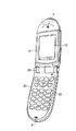
図1は、この発明に係わる折り畳み型電子機器の一実施形態である折り畳み型携帯電話機の外観を示す斜視図である。なお、図1において図8と同一部分には同一符号を付して示す。
【0015】
この折り畳み型携帯電話機は、第1の筐体10と第2の筐体20とをヒンジ部30により回動自在に連結したもので、第1の筐体10には受話用のスピーカ11および表示器12が設けられている。表示器12は例えばLCD(Liquid Crystal Display)からなり、送受信メッセージをはじめ、携帯電話機内のメモリに記憶された電話帳や送受信履歴等の管理情報、およびバッテリ残量や受信電界強度等の携帯電話機の動作状態を表す情報を表示するために用いられる。
【0016】
第2の筐体20には、送話用のマイクロホン21およびキーパッド22が設けられている。このうちキーパッド22は、ダイヤルキーおよび機能キーを備え、発信先の電話番号やメールアドレス、送信メッセージ等を入力するために使用する。
【0017】
ところで、上記折り畳み型携帯電話機では、第1の筐体10内に実装された回路と、第2の筐体20内に実装された回路との間を接続するために、フレキシブル基板を使用している。
【0018】
図2乃至図5はそれぞれ、第1の筐体10内に実装された回路と第2の筐体20内に実装された回路との間を接続構造を説明する図である。なおこれら図2乃至図5において、図1および図8と同一部分には同一符号を付して示す。
【0019】
フレキシブル基板40は図8(a)に示す構造をなすものである。すなわち、フレキシブル基板40は、第1の帯状部41と第2の帯状部42とを中間部43によりクランク状に一体に接続したものであり、基板の片面あるいは両面には複数本の配線パターンが形成されている。
【0020】
第1および第2の帯状部41,42の先端部にはそれぞれコネクタ45,46が取着してある。これらのコネクタ45,46はそれぞれ複数の端子を有し、これらの端子は前記配線パターンに接続されている。コネクタ45,46はそれぞれ、実装時に第1および第2の筐体内の回路に設けられた筐体側のコネクタに接続される。
【0021】
フレキシブル基板40は、中間部43を軸として巻き回された状態にて図2に示すようにヒンジ部30の空洞内に収容される。
【0022】
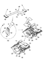
この収容状態におけるフレキシブル基板40の状態を図3に示す。
【0023】
この図3に示すように、フレキシブル基板40は固定チューブ60に巻き付けられている。そして、第1および第2の帯状部41,42の先端部がそれぞれ、ヒンジ部30に形成された開口部を通して第1および第2の筐体10,20内に導き入れられている。そして、当該先端部に取着されたコネクタ45,46がそれぞれ、図3(d)に示すように、第1および第2の筐体10,20内に実装されている第1および第2の回路13,23のコネクタ51,52に接続されている。
【0024】
図4は固定チューブ60の構造を示す斜視図である。
【0025】
この図4に示すように固定チューブ60は、例えば樹脂などを円筒状に形成してなる。そして固定チューブ60には、その長手方向に沿って、スリット61が形成してある。
【0026】
図5は固定チューブ60へのフレキシブル基板40の巻き付け状態を示す図であり、図5(a)は図3中の矢印A1の方向から、また図5(b)は図3中の矢印A1の方向からそれぞれ目視した様子を示している。
【0027】
図3および図5に示すように、フレキシブル基板40の中間部43を図8(a)に示す谷折り位置B−Bを中心にV字型に折り曲げた状態で、固定チューブ60の内部空間に収容してある。そして、帯状部41,42をそれぞれスリット61を通して固定チューブ60の外部へと引出している。さらに帯状部41,42は、互いに異なる巻き方向で固定チューブ60の外周面に巻き付けられている。
【0028】
かくしてこのような構造によれば、帯状部41を巻き回してなる第1のロール状緩衝部と、帯状部42を巻き回してなる第2ロール状緩衝部とが形成される。これらのロール状緩衝部が、ヒンジ部30内の空洞内に収容されることとなる。従って、このように構成された携帯電話機においては、第1および第2の筐体10,20を閉じた状態から開くと、このときの角度の変化量に応じて、フレキシブル基板40の第1および第2の帯状部41,42がそれぞれヒンジ部30の空洞内に収容されたロールから筐体10,20内へ適度な長さだけ引き出される。このため、フレキシブル基板40に加わる引っ張りやコネクタ51,52に加わる過重は吸収される。反対に、第1および第2の筐体10,20を閉じると、このときの角度の変化量に応じて、cの第1および第2の帯状部41,42がそれぞれ筐体10,20内からヒンジ部30の空洞内に形成されているロールに巻き戻される。このため、フレキシブル基板40のたるみや折れ曲がり等は発生しない。
【0029】
ところでこの実施形態では、クランク形状をなすフレキシブル基板40における中間部43を軸として第1および第2の帯状部41,42が巻き回されるのであるが、中間部43は固定チューブ60により抑えられて図5に示すような状態を維持する。このため、フレキシブル基板40の幅が大きく、中間部43の巻き回し方向に関する弾性が大きかったとしても、中間部43を小さな径で巻き回した状態に維持することができる。この結果、第1および第2のロール状緩衝部の外径も小さく抑えることが可能で、ヒンジ部30のサイズ、ひいては携帯電話機全体のサイズを小さく抑えることが可能となる。
【0030】
また、第1および第2のロール状緩衝部がフレキシブル基板40の弾性により拡がろうとする力が固定チューブ60により抑圧されるため、フレキシブル基板40とケース内壁とがこすれづらくるため、フレキシブル基板40の劣化が防止される。
【0031】
また本実施形態の構成によれば、図6に示すように、第1の筐体10側と第2の筐体20側とを接続する同軸ケーブル70を固定チューブ60の内部空間を通して配線することも可能である。そしてこのような配線を行う場合に、中間部43の図8におけるB−Bに沿った長さよりも固定チューブ60の長手方向の長さを大きくしておけば、同軸ケーブル70がフレキシブル基板40の側面とこすれることを防止できる。この結果、フレキシブル基板40および同軸ケーブル70の損傷を防ぐことが可能である。
【0032】
なお、本発明は上記実施形態に限定されるものではない。例えば、第1および第2の帯状部41,42を固定チューブ60へと2回以上巻き付けるようにしても良い。あるいは、第1の帯状部41と第2の帯状部42とで、固定チューブ60への巻き数を相互に異ならせてもよい。
【0033】
また前記実施形態では、折り畳み型電子機器として折り畳み型携帯電話機を例にとって説明した。しかし、これに限定されるものではなく、ノート型パーソナルコンピュータのディスプレイ側筐体とキーボード側筐体との間の接続や、ビデオカメラの本体と表示部との間の接続にもこの発明を適用することができ、さらには携帯情報端末や電子手帳、電子辞書等にも同様に適用可能である。
【0034】
また、図6に示すように同軸ケーブル70を配線する場合には、図7に示すように、固定チューブ60と同様な構造で径が小さな固定チューブ80を用いるようにしても良い。
【0035】
このほか、本発明の要旨を逸脱しない範囲で種々の変形実施が可能である。
【0036】
【発明の効果】
本発明によれば、フレキシブル基板を、その中間部をチューブの内部空間に収容するとともに、前記第1および第2の帯状部を前記スリットを通して前記チューブの外側へとそれぞれ引出し、前記第1および第2の帯状部の先端を開口部を通してそれぞれ第1および第2の筐体内に延在させて前記第1および第2の回路に接続している。
【0037】
従ってこの発明によれば、中間部がチューブにより規制されて一定以上には拡がることが阻止されるので、中間部によって帯状部の巻き径が押し拡げられることがなく、フレキシブル基板全体での外径が小さくされる。この結果、フレキシブル基板を巻き回してなるロール状緩衝部の外径を小さく抑え、これにより機器の小型化および機器の信頼性の向上を図った折り畳み型電子機器を提供できる。
【図面の簡単な説明】
【図1】本発明に係わる折り畳み型電子機器の一実施形態である折り畳み型携帯電話機の外観を示す斜視図。
【図2】フレキシブル基板の配置を示す斜視図。
【図3】ヒンジ部の空洞内に収容された状態におけるフレキシブル基板の状態を示す斜視図。
【図4】固定チューブの斜視図。
【図5】固定チューブ60へのフレキシブル基板40の巻き付け状態を示す図。
【図6】同軸ケーブルを固定チューブの内部空間を通して配線する様子を示す図。
【図7】同軸ケーブルを固定チューブの内部空間を通して配線する様子の変形例を示す図。
【図8】本発明の基礎技術を説明する図。
【符号の説明】
10…第1の筐体
13…第1の回路
20…第2の筐体
23…第2の回路
30…ヒンジ部
40…フレキシブル基板
41…第1の帯状部
42…第2の帯状部
43…中間部
45,46…コネクタ
51,52…コネクタ
60…固定チューブ
61…スリット
70…同軸ケーブル
80…固定チューブ[0001]
BACKGROUND OF THE INVENTION
The present invention relates to a foldable electronic device typified by, for example, a cellular phone or a portable information terminal having a foldable structure.
[0002]
[Prior art]
Conventionally, a foldable mobile phone includes, for example, a first casing provided with a receiving speaker and a display, and a second casing provided with a transmitting microphone and a keypad via a hinge. It is comprised so that rotation is possible. This type of mobile phone is advantageous in that good portability can be obtained by folding the case to reduce the size during standby, and high operability and visibility can be secured by expanding the case during communication.
[0003]
By the way, in this type of mobile phone, it is necessary to electrically connect the circuit mounted in the first housing and the circuit mounted in the second housing via a hinge. Is performed using a flexible substrate.
[0004]
FIG. 8 is a perspective view showing a main configuration of a foldable electronic device, which has been filed as Japanese Patent Application No. 2001-171599 by the applicant, together with a connection procedure thereof.
[0005]
The
[0006]
In this
[0007]
[Problems to be solved by the invention]
However, in a mobile phone or the like, the number of signal lines to be exchanged between two cases is very large in order to realize advanced functions. For this reason, the width of the
[0008]
The
[0009]
When the outer diameter of the roll-shaped buffer portion increases, the
[0010]
The present invention has been made in consideration of such circumstances, and the object of the present invention is to keep the outer diameter of a roll-shaped buffer portion formed by winding a flexible substrate small, thereby reducing the size of the device and the device. It is an object of the present invention to provide a foldable electronic device that is improved in reliability.
[0011]
[Means for Solving the Problems]
In order to achieve the above object, the first aspect of the present invention connects the first housing and the second housing in a rotatable manner by a hinge portion having an opening communicating between the inside of the housings. In the foldable electronic device thus formed, a flexible substrate that connects between the first circuit housed in the first housing and the second circuit housed in the second housing, and the longitudinal direction And the flexible substrate is formed by integrally forming the first and second belt-like portions and an intermediate portion connecting these belt-like portions in a crank shape, The intermediate portion is accommodated in the inner space of the tube, and the first and second belt-like portions are respectively drawn out to the outside of the tube through the slit, and the first and second belt-like portions are formed on the outer surface of the tube. After winding Connected to the first and second belt-like portion said first and second circuits respectively extend into the first and second housing tip through the opening of the.
In order to achieve the above object, the second aspect of the present invention allows the first casing and the second casing to be freely rotated by a hinge portion having an opening communicating between the casings. In a foldable electronic device that is connected, a flexible substrate that connects between a first circuit housed in the first housing and a second circuit housed in the second housing; A tube having slits formed in a direction, and the flexible substrate includes an intermediate portion accommodated in the hinge portion, and first and second strips connected to the intermediate portion and passing through the opening. And the intermediate portion is accommodated in the inner space of the tube, and the first and second belt-like portions are wound around the outer surface of the tube, and then the first and second casings are respectively formed. And extending the first and second circuits It was connected.
In order to achieve the above object, the third aspect of the present invention enables the first casing and the second casing to be freely rotated by a hinge portion having an opening communicating between the casings. In a foldable electronic device that is connected, a flexible substrate that connects between a first circuit housed in the first housing and a second circuit housed in the second housing; A tube having a slit formed in a direction, and a cable wired between the first housing and the second housing, wherein the flexible substrate has first and second strip shapes. And an intermediate portion connecting these belt-like portions in a crank shape are integrally formed, the intermediate portion is accommodated in the internal space of the tube, and the first and second belt-like portions are passed through the slits. Each pulled out to the outside of the tube, The leading ends of the first and second belt-shaped portions are extended through the openings into the first and second housings, respectively, and connected to the first and second circuits, and the cable is inserted through the tube. .
In order to achieve the above object, the fourth aspect of the present invention allows the first casing and the second casing to be rotated by a hinge portion having an opening communicating between the casings. In a foldable electronic device that is connected, a flexible substrate that connects between a first circuit housed in the first housing and a second circuit housed in the second housing; A tube having a slit formed in a direction, and a cable wired between the first casing and the second casing, and the flexible substrate is accommodated in the hinge portion. The intermediate portion and the first and second strips connected to the intermediate portion and passing through the opening are integrally formed, and the intermediate portion is accommodated in the internal space of the tube, and the first and second Two strips extending into the first and second housings, respectively. Connected to said first and second circuits, was further inserting the cable into the tube.
[0012]
Therefore, according to the present invention, the flexible substrate is used in a state of being wound around the intermediate portion, but the intermediate portion is restricted by the tube and is prevented from expanding beyond a certain level. For this reason, the winding diameter of the belt-shaped portion is not expanded by the intermediate portion, and the outer diameter of the entire flexible substrate is reduced.
[0013]
DETAILED DESCRIPTION OF THE INVENTION
Hereinafter, an embodiment of the present invention will be described with reference to the drawings.
[0014]
FIG. 1 is a perspective view showing the appearance of a foldable mobile phone which is an embodiment of a foldable electronic apparatus according to the present invention. In FIG. 1, the same parts as those in FIG.
[0015]
In this foldable mobile phone, a
[0016]
The
[0017]
By the way, in the foldable mobile phone, a flexible substrate is used to connect between a circuit mounted in the
[0018]
2 to 5 are diagrams for explaining a connection structure between a circuit mounted in the
[0019]
The
[0020]
[0021]
The
[0022]
The state of the
[0023]
As shown in FIG. 3, the
[0024]
FIG. 4 is a perspective view showing the structure of the fixed
[0025]
As shown in FIG. 4, the fixed
[0026]
FIG. 5 is a diagram showing a state in which the
[0027]
As shown in FIGS. 3 and 5, the
[0028]
Thus, according to such a structure, a first roll-shaped buffer portion formed by winding the belt-shaped
[0029]
By the way, in this embodiment, the first and second belt-
[0030]
Moreover, since the force which the 1st and 2nd roll-shaped buffer part tends to spread by the elasticity of the
[0031]
Further, according to the configuration of the present embodiment, as shown in FIG. 6, the
[0032]
The present invention is not limited to the above embodiment. For example, you may make it wind the 1st and 2nd strip | belt-shaped
[0033]
In the above-described embodiment, a foldable mobile phone has been described as an example of the foldable electronic device. However, the present invention is not limited to this, and the present invention is also applied to the connection between the display-side housing and the keyboard-side housing of a notebook personal computer and the connection between the video camera body and the display unit. Furthermore, the present invention can be similarly applied to a portable information terminal, an electronic notebook, an electronic dictionary, and the like.
[0034]
When the
[0035]
In addition, various modifications can be made without departing from the scope of the present invention.
[0036]
【The invention's effect】
According to the present invention, the flexible substrate is accommodated in the inner space of the tube at the intermediate portion thereof, and the first and second belt-shaped portions are drawn out to the outside of the tube through the slit, respectively. The leading ends of the two belt-like portions extend into the first and second casings through the openings, respectively, and are connected to the first and second circuits.
[0037]
Therefore, according to the present invention, since the intermediate portion is restricted by the tube and is prevented from expanding beyond a certain level, the winding diameter of the band-shaped portion is not expanded by the intermediate portion, and the outer diameter of the entire flexible substrate is reduced. Is reduced. As a result, it is possible to provide a foldable electronic device in which the outer diameter of the roll-shaped buffer portion formed by winding the flexible substrate is kept small, thereby reducing the size of the device and improving the reliability of the device.
[Brief description of the drawings]
FIG. 1 is a perspective view showing an appearance of a foldable mobile phone which is an embodiment of a foldable electronic apparatus according to the present invention.
FIG. 2 is a perspective view showing an arrangement of a flexible substrate.
FIG. 3 is a perspective view showing a state of the flexible substrate in a state of being accommodated in a cavity of the hinge portion.
FIG. 4 is a perspective view of a fixed tube.
FIG. 5 is a view showing a state where the
FIG. 6 is a diagram showing a state in which a coaxial cable is wired through an internal space of a fixed tube.
FIG. 7 is a view showing a modification of a state in which the coaxial cable is wired through the internal space of the fixed tube.
FIG. 8 is a diagram illustrating a basic technique of the present invention.
[Explanation of symbols]
DESCRIPTION OF
Claims (7)
前記第1の筐体内に収容される第1の回路と前記第2の筐体内に収容される第2の回路との間を接続するフレキシブル基板と、
長手方向に沿ってスリットが形成されたチューブとを具備し、
前記フレキシブル基板は、第1および第2の帯状部とこれらの帯状部をクランク状に接続する中間部とを一体に形成してなり、
前記中間部を前記チューブの内部空間に収容するとともに、前記第1および第2の帯状部を前記スリットを通して前記チューブの外側へとそれぞれ引出し、前記第1および第2の帯状部を前記チューブの外面に巻き付けた上で、前記第1および第2の帯状部の先端を前記開口部を通してそれぞれ第1および第2の筐体内に延在させて前記第1および第2の回路に接続したことを特徴とする折り畳み型電子機器。In a foldable electronic device in which a first housing and a second housing are rotatably connected by a hinge portion having an opening communicating between the housings,
A flexible substrate that connects between a first circuit housed in the first housing and a second circuit housed in the second housing;
A tube having a slit formed along the longitudinal direction,
The flexible substrate is formed by integrally forming first and second belt-like portions and an intermediate portion connecting these belt-like portions in a crank shape,
The intermediate portion is accommodated in the inner space of the tube, and the first and second belt-like portions are respectively drawn out to the outside of the tube through the slit, and the first and second belt-like portions are pulled out to the outer surface of the tube. And the ends of the first and second belt-like portions are extended into the first and second casings through the openings and connected to the first and second circuits, respectively. Folding type electronic equipment.
前記第1の筐体内に収容される第1の回路と前記第2の筐体内に収容される第2の回路との間を接続するフレキシブル基板と、
長手方向に沿ってスリットが形成されたチューブとを具備し、
前記フレキシブル基板は、前記ヒンジ部に収容される中間部とこの中間部と接続し前記開口部を通る第1および第2の帯状部とを一体に形成してなり、
前記中間部を前記チューブの内部空間に収容するとともに、前記第1および第2の帯状部を前記チューブの外面に巻き付けた上でそれぞれ第1および第2の筐体内に延在させて前記第1および第2の回路に接続したことを特徴とする折り畳み型電子機器。In a foldable electronic device in which a first housing and a second housing are rotatably connected by a hinge portion having an opening communicating between the housings,
A flexible substrate that connects between a first circuit housed in the first housing and a second circuit housed in the second housing;
A tube having a slit formed along the longitudinal direction,
The flexible substrate is formed by integrally forming an intermediate portion accommodated in the hinge portion and first and second belt-like portions connected to the intermediate portion and passing through the opening,
The intermediate portion is accommodated in the inner space of the tube, and the first and second belt-shaped portions are wound around the outer surface of the tube and then extended into the first and second casings, respectively. And a foldable electronic device connected to the second circuit.
前記第1の筐体内に収容される第1の回路と前記第2の筐体内に収容される第2の回路との間を接続するフレキシブル基板と、
長手方向に沿ってスリットが形成されたチューブと、
前記第1の筐体と前記第2の筐体との間に配線されるケーブルとを具備し、
前記フレキシブル基板は、第1および第2の帯状部とこれらの帯状部をクランク状に接続する中間部とを一体に形成してなり、
前記中間部を前記チューブの内部空間に収容するとともに、前記第1および第2の帯状部を前記スリットを通して前記チューブの外側へとそれぞれ引出し、前記第1および第2の帯状部の先端を前記開口部を通してそれぞれ第1および第2の筐体内に延在させて前記第1および第2の回路に接続し、さらに前記チューブに前記ケーブルを挿通させたことを特徴とする折り畳み型電子機器。In a foldable electronic device in which a first housing and a second housing are rotatably connected by a hinge portion having an opening communicating between the housings,
A flexible substrate that connects between a first circuit housed in the first housing and a second circuit housed in the second housing;
A tube with slits formed along the longitudinal direction;
Comprising a cable wired between the first housing and the second housing;
The flexible substrate is formed by integrally forming first and second belt-like portions and an intermediate portion connecting these belt-like portions in a crank shape,
The intermediate portion is accommodated in the internal space of the tube, and the first and second belt-like portions are respectively drawn out to the outside of the tube through the slit, and the ends of the first and second belt-like portions are opened in the opening. A foldable electronic device characterized in that each of the first and second casings extends through the part, is connected to the first and second circuits, and the cable is inserted through the tube.
前記第1の筐体内に収容される第1の回路と前記第2の筐体内に収容される第2の回路との間を接続するフレキシブル基板と、
長手方向に沿ってスリットが形成されたチューブと、
前記第1の筐体と前記第2の筐体との間に配線されるケーブルとを具備し、
前記フレキシブル基板は、前記ヒンジ部に収容される中間部とこの中間部と接続し前記開口部を通る第1および第2の帯状部とを一体に形成してなり、
前記中間部を前記チューブの内部空間に収容するとともに、前記第1および第2の帯状部をそれぞれ第1および第2の筐体内に延在させて前記第1および第2の回路に接続し、さらに前記チューブに前記ケーブルを挿通させたことを特徴とする折り畳み型電子機器。In a foldable electronic device in which a first housing and a second housing are rotatably connected by a hinge portion having an opening communicating between the housings,
A flexible substrate that connects between a first circuit housed in the first housing and a second circuit housed in the second housing;
A tube with slits formed along the longitudinal direction;
Comprising a cable wired between the first housing and the second housing;
The flexible substrate is formed by integrally forming an intermediate portion accommodated in the hinge portion and first and second belt-like portions connected to the intermediate portion and passing through the opening,
The intermediate portion is accommodated in the internal space of the tube, and the first and second belt-like portions are respectively extended into the first and second housings and connected to the first and second circuits, Furthermore, the foldable electronic apparatus characterized in that the cable is inserted through the tube.
Priority Applications (1)
| Application Number | Priority Date | Filing Date | Title |
|---|---|---|---|
| JP2002050126A JP3842670B2 (en) | 2002-02-26 | 2002-02-26 | Foldable electronic device |
Applications Claiming Priority (1)
| Application Number | Priority Date | Filing Date | Title |
|---|---|---|---|
| JP2002050126A JP3842670B2 (en) | 2002-02-26 | 2002-02-26 | Foldable electronic device |
Publications (3)
| Publication Number | Publication Date |
|---|---|
| JP2003258961A JP2003258961A (en) | 2003-09-12 |
| JP2003258961A5 JP2003258961A5 (en) | 2005-08-18 |
| JP3842670B2 true JP3842670B2 (en) | 2006-11-08 |
Family
ID=28662462
Family Applications (1)
| Application Number | Title | Priority Date | Filing Date |
|---|---|---|---|
| JP2002050126A Expired - Fee Related JP3842670B2 (en) | 2002-02-26 | 2002-02-26 | Foldable electronic device |
Country Status (1)
| Country | Link |
|---|---|
| JP (1) | JP3842670B2 (en) |
Families Citing this family (3)
| Publication number | Priority date | Publication date | Assignee | Title |
|---|---|---|---|---|
| JP4708092B2 (en) * | 2005-05-30 | 2011-06-22 | 京セラ株式会社 | Electronics |
| WO2007105266A1 (en) * | 2006-03-10 | 2007-09-20 | Fujitsu Limited | Wiring fixation structure and electronic apparatus |
| JP2015085451A (en) * | 2013-10-31 | 2015-05-07 | セイコーエプソン株式会社 | Robot |
-
2002
- 2002-02-26 JP JP2002050126A patent/JP3842670B2/en not_active Expired - Fee Related
Also Published As
| Publication number | Publication date |
|---|---|
| JP2003258961A (en) | 2003-09-12 |
Similar Documents
| Publication | Publication Date | Title |
|---|---|---|
| JP2002368440A (en) | Folding type electronic device and its flexible board | |
| KR100231747B1 (en) | Method and apparatus for routing conductor | |
| US7248903B2 (en) | Mobile instrument with flexible printed wiring board | |
| JP4234379B2 (en) | Folding terminal hinge device and folding terminal | |
| US7336782B2 (en) | Wiring structure for folding portable device | |
| US8153896B2 (en) | Electrical-wire support apparatus | |
| JP2006507726A (en) | Flexible conductor connected between two parts of a portable electronic device | |
| JP2007258593A (en) | Electronic device | |
| JPH07288860A (en) | Portable radio telephone set | |
| US20040231105A1 (en) | Hinge apparatus and wiring member for use in hinge apparatus | |
| JP3842670B2 (en) | Foldable electronic device | |
| JP2006093461A (en) | Folding electronic equipment | |
| JP2002300247A (en) | Foldable portable telephone system | |
| JP2012034206A (en) | Electronic apparatus | |
| JP4048291B2 (en) | Folding electrical equipment | |
| JP3943413B2 (en) | Foldable electronic device | |
| JP4458828B2 (en) | Portable device | |
| JP4094420B2 (en) | Flexible wiring board and portable electronic device using the same | |
| JP2003037375A (en) | Foldable electronic equipment | |
| JP3515490B2 (en) | Flexible printed circuit board and foldable mobile phone terminal having flexible printed circuit board | |
| JP2003110210A (en) | Flexible wiring substrate and folding electronic equipment | |
| JP4051297B2 (en) | Mobile terminal device | |
| JP4294327B2 (en) | Mobile terminal device | |
| JP2006041139A (en) | Electronic apparatus | |
| JP3800607B2 (en) | Hinge connector and electronic device |
Legal Events
| Date | Code | Title | Description |
|---|---|---|---|
| A521 | Written amendment |
Free format text: JAPANESE INTERMEDIATE CODE: A523 Effective date: 20050204 |
|
| A621 | Written request for application examination |
Free format text: JAPANESE INTERMEDIATE CODE: A621 Effective date: 20050204 |
|
| A131 | Notification of reasons for refusal |
Free format text: JAPANESE INTERMEDIATE CODE: A131 Effective date: 20060425 |
|
| A521 | Written amendment |
Free format text: JAPANESE INTERMEDIATE CODE: A523 Effective date: 20060623 |
|
| TRDD | Decision of grant or rejection written | ||
| A01 | Written decision to grant a patent or to grant a registration (utility model) |
Free format text: JAPANESE INTERMEDIATE CODE: A01 Effective date: 20060808 |
|
| A61 | First payment of annual fees (during grant procedure) |
Free format text: JAPANESE INTERMEDIATE CODE: A61 Effective date: 20060810 |
|
| LAPS | Cancellation because of no payment of annual fees |