JP3838357B2 - Control device for internal combustion engine - Google Patents
Control device for internal combustion engine Download PDFInfo
- Publication number
- JP3838357B2 JP3838357B2 JP2002310668A JP2002310668A JP3838357B2 JP 3838357 B2 JP3838357 B2 JP 3838357B2 JP 2002310668 A JP2002310668 A JP 2002310668A JP 2002310668 A JP2002310668 A JP 2002310668A JP 3838357 B2 JP3838357 B2 JP 3838357B2
- Authority
- JP
- Japan
- Prior art keywords
- fuel
- component
- intake
- amount
- internal combustion
- Prior art date
- Legal status (The legal status is an assumption and is not a legal conclusion. Google has not performed a legal analysis and makes no representation as to the accuracy of the status listed.)
- Expired - Fee Related
Links
- 238000002485 combustion reaction Methods 0.000 title claims description 106
- 239000000446 fuel Substances 0.000 claims description 271
- 238000002347 injection Methods 0.000 claims description 24
- 239000007924 injection Substances 0.000 claims description 24
- 239000000470 constituent Substances 0.000 claims description 17
- 238000004821 distillation Methods 0.000 claims description 9
- 238000009835 boiling Methods 0.000 description 184
- 230000014509 gene expression Effects 0.000 description 26
- TVMXDCGIABBOFY-UHFFFAOYSA-N octane Chemical compound CCCCCCCC TVMXDCGIABBOFY-UHFFFAOYSA-N 0.000 description 25
- 238000012937 correction Methods 0.000 description 17
- 238000011144 upstream manufacturing Methods 0.000 description 16
- 238000000034 method Methods 0.000 description 14
- 230000008021 deposition Effects 0.000 description 12
- 230000001052 transient effect Effects 0.000 description 11
- 239000000498 cooling water Substances 0.000 description 10
- 238000012545 processing Methods 0.000 description 9
- 239000007789 gas Substances 0.000 description 8
- 230000006399 behavior Effects 0.000 description 6
- 230000005855 radiation Effects 0.000 description 6
- 230000004044 response Effects 0.000 description 6
- 230000017525 heat dissipation Effects 0.000 description 5
- 238000010438 heat treatment Methods 0.000 description 5
- 229920006395 saturated elastomer Polymers 0.000 description 5
- XLYOFNOQVPJJNP-UHFFFAOYSA-N water Substances O XLYOFNOQVPJJNP-UHFFFAOYSA-N 0.000 description 5
- 238000009529 body temperature measurement Methods 0.000 description 4
- 230000007423 decrease Effects 0.000 description 4
- 238000010586 diagram Methods 0.000 description 4
- 239000000203 mixture Substances 0.000 description 4
- UHOVQNZJYSORNB-UHFFFAOYSA-N Benzene Chemical compound C1=CC=CC=C1 UHOVQNZJYSORNB-UHFFFAOYSA-N 0.000 description 3
- OKTJSMMVPCPJKN-UHFFFAOYSA-N Carbon Chemical compound [C] OKTJSMMVPCPJKN-UHFFFAOYSA-N 0.000 description 3
- 229910052799 carbon Inorganic materials 0.000 description 3
- 238000006243 chemical reaction Methods 0.000 description 3
- 239000002826 coolant Substances 0.000 description 3
- 230000003247 decreasing effect Effects 0.000 description 3
- 238000000889 atomisation Methods 0.000 description 2
- 230000003197 catalytic effect Effects 0.000 description 2
- 238000004891 communication Methods 0.000 description 2
- 238000004134 energy conservation Methods 0.000 description 2
- VNWKTOKETHGBQD-UHFFFAOYSA-N methane Chemical compound C VNWKTOKETHGBQD-UHFFFAOYSA-N 0.000 description 2
- 238000005192 partition Methods 0.000 description 2
- BASFCYQUMIYNBI-UHFFFAOYSA-N platinum Chemical compound [Pt] BASFCYQUMIYNBI-UHFFFAOYSA-N 0.000 description 2
- OTMSDBZUPAUEDD-UHFFFAOYSA-N Ethane Chemical compound CC OTMSDBZUPAUEDD-UHFFFAOYSA-N 0.000 description 1
- QVGXLLKOCUKJST-UHFFFAOYSA-N atomic oxygen Chemical compound [O] QVGXLLKOCUKJST-UHFFFAOYSA-N 0.000 description 1
- 239000003054 catalyst Substances 0.000 description 1
- 230000006835 compression Effects 0.000 description 1
- 238000007906 compression Methods 0.000 description 1
- 238000001514 detection method Methods 0.000 description 1
- 238000006073 displacement reaction Methods 0.000 description 1
- 238000001704 evaporation Methods 0.000 description 1
- 230000008020 evaporation Effects 0.000 description 1
- 238000002474 experimental method Methods 0.000 description 1
- 238000004880 explosion Methods 0.000 description 1
- 238000012986 modification Methods 0.000 description 1
- 230000004048 modification Effects 0.000 description 1
- 229910052760 oxygen Inorganic materials 0.000 description 1
- 239000001301 oxygen Substances 0.000 description 1
- 229910052697 platinum Inorganic materials 0.000 description 1
- 238000009834 vaporization Methods 0.000 description 1
- 230000008016 vaporization Effects 0.000 description 1
Images


Classifications
-
- Y—GENERAL TAGGING OF NEW TECHNOLOGICAL DEVELOPMENTS; GENERAL TAGGING OF CROSS-SECTIONAL TECHNOLOGIES SPANNING OVER SEVERAL SECTIONS OF THE IPC; TECHNICAL SUBJECTS COVERED BY FORMER USPC CROSS-REFERENCE ART COLLECTIONS [XRACs] AND DIGESTS
- Y02—TECHNOLOGIES OR APPLICATIONS FOR MITIGATION OR ADAPTATION AGAINST CLIMATE CHANGE
- Y02T—CLIMATE CHANGE MITIGATION TECHNOLOGIES RELATED TO TRANSPORTATION
- Y02T10/00—Road transport of goods or passengers
- Y02T10/10—Internal combustion engine [ICE] based vehicles
- Y02T10/40—Engine management systems
Landscapes
- Electrical Control Of Ignition Timing (AREA)
- Electrical Control Of Air Or Fuel Supplied To Internal-Combustion Engine (AREA)
- Combined Controls Of Internal Combustion Engines (AREA)
Description
【0001】
【発明の属する技術分野】
本発明は、内燃機関の制御装置に係り、特に内燃機関の運転状態が良好な状態になるように点火時期等の機関制御パラメータを制御する制御装置に関する。
【0002】
【従来の技術】
内燃機関のノック限界は同内燃機関に使用される燃料(ガソリン)のオクタン価に応じて変化し、使用される燃料のオクタン価が高くなるほどノック限界は進角側に移動する。従って、内燃機関において最適な燃焼状態を得るためには、使用される燃料のオクタン価に応じて点火時期を変更する必要がある。このため、下記特許文献1に開示された内燃機関の点火時期制御装置は、レギュラガソリンと同レギュラガソリンよりもオクタン価が高いプレミアムガソリンの何れが内燃機関の燃料として使用されているかを検出する燃料性状センサを備え、同燃料性状センサの検出結果に応じて内燃機関の点火時期を変更するようになっている。
【0003】
【特許文献1】
特開平5−79439号公報
【0004】
【発明が解決しようとする課題】
ところで、内燃機関の燃料として広く使用されている燃料(ガソリン)は、炭素数が少なくて沸点が低い低沸点成分(例えば、メタン、エタン)や炭素数が比較的多くて沸点が比較的高い高沸点成分(例えば、ベンゼン)等のように、蒸留性状(沸点、飽和蒸気圧)の異なる複数の燃料成分から構成される混合物である。また、通常、前記低沸点成分はオクタン価が低く、前記高沸点成分は同低沸点成分よりもオクタン価が高い。換言すれば、蒸留性状の異なる各燃料成分のオクタン価は燃料成分毎に異なる。従って、混合物である燃料(ガソリン)自体(全体)のオクタン価は、これら複数の燃料成分の各々のオクタン価と、それらの成分比率とに応じて変化する。
【0005】
一方、燃料を燃焼室に接続された吸気通路内に噴射する燃料噴射手段(インジェクタ)を備えた内燃機関においては、燃料噴射手段から噴射された燃料は、その一部が吸気通路壁面や吸気弁等の吸気通路構成部材に付着する。その際の吸気通路構成部材に対する燃料の付着挙動は、同燃料の各燃料成分の蒸留性状が異なることから同燃料成分毎に異なる。特に、内燃機関が過渡運転状態にあって吸気通路内の圧力や温度が急激に変化すると、各燃料成分の間で気化又は液化の程度が急激に異なるようになり、吸気通路構成部材に対する各燃料成分の付着挙動が各燃料成分の間で急激に異なるようになる。その結果、シリンダ内(筒内)に流入する各燃料成分の間の成分比率が一時的に変化し、筒内に流入する(筒内で実際に燃焼される)燃料全体としてのオクタン価(以下、「筒内オクタン価」と称呼する。)も使用される燃料自体のオクタン価から一時的に変化する。
【0006】
従って、上記開示された装置においては、使用される燃料(自体)のオクタン価に応じて点火時期を決定しても、特に、過渡運転状態において、筒内に流入する燃料の筒内オクタン価が燃料自体のオクタン価から一時的に変化することから最適な燃焼状態を得ることができない場合(決定された点火時期が最適な点火時期とはならない場合)があるという問題がある。
【0007】
従って、本発明の目的は、内燃機関が過渡運転状態にあるときでも、その運転状態を良好な状態に維持できるように点火時期等の機関制御パラメータを制御することができる内燃機関の制御装置を提供することにある。
【0008】
【本発明の概要】
本発明の特徴は、蒸留性状の異なる複数の燃料成分を有する燃料を燃焼室に接続された吸気通路内に噴射する燃料噴射手段を備えた内燃機関に適用される内燃機関の制御装置が、前記吸気通路を構成する部材に付着する各燃料成分の燃料付着量を同燃料成分毎に推定する燃料付着量推定手段と、前記推定された各燃料成分の燃料付着量に基いて前記燃焼室内に流入する同各燃料成分の筒内流入燃料量を同燃料成分毎に推定する筒内流入燃料量推定手段と、前記推定された各燃料成分の筒内流入燃料量に基いて前記内燃機関の運転状態を良好な状態になるように調整するための機関制御パラメータを決定する機関制御パラメータ決定手段とを備えたことにある。
【0009】
この場合、前記吸気通路を構成する部材は、吸気管(インテークマニホールド)、吸気弁(特に、吸気弁の背面)、吸気通路に設けられるSCV等の吸気制御弁を含んでよい。また、前記機関制御パラメータは、例えば、点火時期、目標空燃比、吸気弁及び排気弁の開閉タイミング、燃料の噴射時期であって、これらに限定されない。
【0010】
また、上記内燃機関の制御装置においては、前記燃料付着量推定手段は、前記燃料の燃料成分毎に決定されるとともに前記燃料噴射手段から噴射される前記各燃料成分のうち前記吸気通路構成部材に付着する同各燃料成分の割合を表す各燃料成分の吸気通路付着率と、前記燃料の燃料成分毎に決定されるとともに前記吸気通路構成部材に付着している前記各燃料成分のうち同吸気通路構成部材に付着したまま残留する同各燃料成分の割合を表す各燃料成分の吸気通路残留率と、を用いて前記吸気通路構成部材に付着する各燃料成分の燃料付着量を推定するように構成されることが好適である。
【0011】
吸気通路構成部材に対する燃料の付着挙動(例えば、吸気通路付着率、吸気通路残留率等を用いる燃料付着モデルで表される。)は、燃料を構成する蒸留性状の異なる複数の燃料成分毎に異なる。従って、上記構成のように、吸気通路構成部材に付着する各燃料成分の燃料付着量を同燃料成分毎に区別して推定することにより、各燃料成分の吸気通路構成部材への燃料付着量がそれぞれ精度良く推定される。
【0012】
また、上記構成によれば、前記推定された各燃料成分の燃料付着量に基いて燃焼室内に流入する同各燃料成分の筒内流入燃料量が同燃料成分毎に区別して推定されるので、各燃料成分の筒内流入燃料量もそれぞれ精度良く推定される。従って、内燃機関が過渡運転状態にあるときでも、例えば、時々刻々と変化するシリンダ内(筒内)に流入する燃料の各燃料成分の間の成分比率を精度良く求めることができ、この結果、筒内に流入する燃料の筒内オクタン価を精度良く求めることができる。
【0013】
よって、上記のように、前記推定された各燃料成分の筒内流入燃料量に基いて前記内燃機関の運転状態を良好な状態になるように調整するための機関制御パラメータを決定することにより、例えば、時々刻々と変化する筒内に流入する各燃料成分の間の成分比率(筒内に流入する燃料の筒内オクタン価)に基いて点火時期等の機関制御パラメータを決定することができる。従って、内燃機関が過渡運転状態にあるときでも、その運転状態を良好な状態に維持できるように点火時期等の機関制御パラメータを制御することができる。
【0014】
また、上記内燃機関の制御装置が、前記内燃機関の運転状態が定常状態にあるときに同運転状態が良好な状態になる同内燃機関の基本点火時期を記憶した基本点火時期記憶手段を備える場合には、前記機関制御パラメータ決定手段は、前記機関制御パラメータとしての前記内燃機関の点火時期を、前記推定された各燃料成分の筒内流入燃料量に基いて前記基本点火時期から補正することで決定するように構成されることが望ましい。
【0015】
内燃機関における最適な点火時期は、機関の回転速度、吸入空気量、機関の温度(冷却水温)等のノック限界に影響を与える複数の因子の組み合わせに応じて変化する。従って、一般には、これら複数の因子の組み合わせを種々変更した各々の場合において内燃機関が定常状態にあるときに最適な燃焼状態(運転状態)が得られるような基本点火時期を予め実験等により求めておき、内燃機関の制御装置は、それら種々の場合における基本点火時期が格納された基本点火時期記憶手段(ROM内に記憶されたテーブル)を搭載することで、同基本点火時期記憶手段とその時点での上記複数の因子とに基き同時点での点火時期を決定するようになっている。
【0016】
よって、内燃機関の制御装置がかかる基本点火時期記憶手段を備えている場合には、上記のように、内燃機関の点火時期を、前記推定された各燃料成分の筒内流入燃料量に基いて(即ち、例えば、各燃料成分の筒内流入燃料量に基いて得られる筒内に流入する各燃料成分の間の成分比率、筒内に流入する燃料の筒内オクタン価に基いて)、基本点火時期から補正することで決定することにより、基本点火時期を決定するための既存のテーブルをそのまま利用しつつ容易に最適な点火時期を計算することが可能となる。
【0017】
【発明の実施の形態】
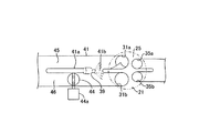
以下、本発明による内燃機関の制御装置の実施形態について図面を参照しつつ説明すると、図1は、同制御装置を火花点火式多気筒(4気筒)内燃機関10に適用したシステムの概略構成を示している。
【0018】
この内燃機関10は、シリンダブロック、シリンダブロックロワーケース、及びオイルパン等を含むシリンダブロック部20と、シリンダブロック部20の上に固定されるシリンダヘッド部30と、シリンダブロック部20にガソリン混合気を供給するための吸気系統40と、シリンダブロック部20からの排ガスを外部に放出するための排気系統50とを含んでいる。
【0019】
シリンダブロック部20は、シリンダ21、ピストン22、コンロッド23、及びクランク軸24を含んでいる。ピストン22はシリンダ21内を往復動し、ピストン22の往復動がコンロッド23を介してクランク軸24に伝達され、これにより同クランク軸24が回転するようになっている。シリンダ21とピストン22のヘッドは、シリンダヘッド部30とともに燃焼室25を形成している。
【0020】
シリンダヘッド部30は、燃焼室25に連通した吸気ポート31、吸気ポート31を開閉する吸気弁32、吸気弁32を駆動するインテークカムシャフトを含むとともに同インテークカムシャフトの位相角を連続的に変更する可変吸気タイミング装置33、可変吸気タイミング装置33のアクチュエータ33a、燃焼室25に連通した排気ポート34、排気ポート34を開閉する排気弁35、排気弁35を駆動するエキゾーストカムシャフト36、点火プラグ37、点火プラグ37に与える高電圧を発生するイグニッションコイルを含むイグナイタ38、及び燃料を吸気ポート31内に噴射するインジェクタ(燃料噴射手段)39を備えている。
【0021】
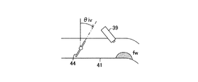
吸気系統40は、吸気ポート31に連通し同吸気ポート31とともに吸気通路を形成するインテークマニホールドを含む吸気管41、吸気管41の端部に設けられたエアフィルタ42、吸気管41内にあって吸気通路の開口断面積を可変とするスロットルバルブ43、及びスワールコントロールバルブ(以下、「SCV」と称呼する。)44を備えている。スロットルバルブ43は、DCモータからなるスロットルバルブアクチュエータ43aにより吸気管41内で回転駆動されるようになっている。SCV44は、前記スロットルバルブ43よりも下流で前記インジェクタ39よりも上流の位置にて前記吸気管41に対し回動可能に支持されるとともに、DCモータからなるSCVアクチュエータ44aにより回転駆動されるようになっている。なお、本明細書においては、インテークマニホールドを含む吸気管41、吸気ポート31、吸気弁32、及びSCV44等を吸気通路を構成する部材(吸気通路構成部材)と称呼する。
【0022】
図2は、一つの気筒(特定の気筒)の燃焼室25、及び同燃焼室25の近傍部分の概略平面図である。図2に示したように、前記吸気ポート31は、実際には各気筒に一対ずつ設けられた吸気ポート31a,31bからなっている。吸気ポート31aは、燃焼室25内にスワール(旋回流)を発生させるようにヘリカル状に形成され所謂スワールポートを構成し、吸気ポート31bは所謂ストレートポートを構成している。吸気管41のサージタンクから各燃焼室25に至る部分(即ち、インテークマニホールドの一部)には、吸気管41の長手方向に沿って伸びる隔壁41aが形成されていて、これにより吸気管41は吸気ポート31aに連通する第1インテークマニホールド45と、吸気ポート31bに連通する第2インテークマニホールド46とに区画されている。前記SCV44は、第2インテークマニホールド46内において回動可能に支持され、第2インテークマニホールド46の開口断面積を変更し得るようになっている。
【0023】
隔壁41aの適宜個所には第1,第2インテークマニホールド45,46を連通する連通路41bが形成されていて、前記インジェクタ39は同連通路41bの近傍位置に固定され、吸気ポート31a,31bに向けて燃料を噴射するようになっている。これにより、インジェクタ39から噴射された燃料は、その一部が前記吸気通路構成部材に付着する。
【0024】
再び図1を参照すると、排気系統50は、排気ポート34に連通したエキゾーストマニホールド51、エキゾーストマニホールド51に接続されたエキゾーストパイプ52、及びエキゾーストパイプ52に介装された触媒コンバータ(三元触媒装置)53を備えている。
【0025】
一方、このシステムは、熱線式エアフローメータ61、吸気温センサ62、大気圧センサ(スロットルバルブ上流圧力センサ)63、スロットルポジションセンサ64、SCV開度センサ65、カムポジションセンサ66、クランクポジションセンサ67、水温センサ68、O2センサ69、及びアクセル開度センサ81を備えている。
【0026】
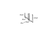
エアフローメータ61は、概略斜視図である図3に示したように、吸気管41内を流れる吸入空気の一部をバイパスさせるバイパス通路と、このバイパス通路にバイパスされた吸入空気の質量流量を計測する熱線計量部61aと、計測された質量流量に応じた電圧Vgを出力する信号処理部61bとからなっている。熱線計量部61aは、その拡大斜視図である図4に示したように、白金熱線からなる吸気温計測用抵抗(ボビン部)61a1と、同吸気温計測用抵抗61a1を前記信号処理部61bに連結して保持するサポート部61a2と、加熱用抵抗(ヒータ)61a3と、同加熱用抵抗61a3を前記信号処理部61bに連結して保持するサポート部61a4とを備えている。信号処理部61bは、吸気温計測用抵抗61a1と加熱用抵抗61a3とで構成されたブリッジ回路を備え、このブリッジ回路により吸気温計測用抵抗61a1と加熱用抵抗61a3との温度差を常に一定に維持するように同加熱用抵抗61a3に供給する電力を調整するとともに、この供給する電力を前記電圧Vgに変換して出力するようになっている。
【0027】
吸気温センサ62は、エアフローメータ61内に備えられていて、吸入空気の温度を検出し、吸気温度THAを表す信号を出力するようになっている。大気圧センサ63は、スロットルバルブ43の上流の圧力(即ち、大気圧)を検出し、スロットルバルブ上流圧力Paを表す信号を出力するようになっている。スロットルポジションセンサ64は、スロットルバルブ43の開度を検出し、スロットルバルブ開度TAを表す信号を出力するようになっている。SCV開度センサ65は、SCV44の開度を検出し、SCV開度θivを表す信号を出力するようになっている。カムポジションセンサ66は、インテークカムシャフトが90°回転する毎に(即ち、クランク軸24が180°回転する毎に)一つのパルスを有する信号(G2信号)を発生するようになっている。クランクポジションセンサ67は、クランク軸24が10°回転する毎に幅狭のパルスを有するとともに同クランク軸24が360°回転する毎に幅広のパルスを有する信号を出力するようになっている。この信号は、エンジン回転速度Neを表す。水温センサ68は、内燃機関10の冷却水の温度を検出し、冷却水温THWを表す信号を出力するようになっている。O2センサ69は、触媒コンバータ53に流入する排ガス中の酸素濃度に応じた信号(空燃比が理論空燃比よりもリッチであるか、又はリーンであるかを示す信号)を出力するようになっている。アクセル開度センサ81は、運転者によって操作されるアクセルペダル82の操作量Accpを表す信号を出力するようになっている。
【0028】
電気制御装置70は、互いにバスで接続されたCPU71、CPU71が実行するプログラム、テーブル(ルックアップテーブル、マップ)、定数等を予め記憶したROM72、CPU71が必要に応じてデータを一時的に格納するRAM73、電源が投入された状態でデータを格納するとともに同格納したデータを電源が遮断されている間も保持するバックアップRAM74、及びADコンバータを含むインターフェース75等からなるマイクロコンピュータである。インターフェース75は、前記センサ61〜69,81と接続され、CPU71にセンサ61〜69,81からの信号を供給するとともに、同CPU71の指示に応じて可変吸気タイミング装置33のアクチュエータ33a、イグナイタ38、インジェクタ39、スロットルバルブアクチュエータ43a、及びSCVアクチュエータ44aに駆動信号を送出するようになっている。
【0029】
次に、上記のように構成された制御装置による点火プラグ37の点火時期の決定方法について説明する。以下に述べる処理は、CPU71がプログラムを実行することによりなされる。
【0030】
(吸入空気量相当値KLFWDの決定方法の概要)
この制御装置は、ノック限界に影響を与える因子の一部であるエンジン回転速度Ne、冷却水温THW、及び一気筒当たりの吸入空気量相当値KLFWDの組み合わせを種々変更した各々の場合において内燃機関10が定常状態にあるときに最適な燃焼状態を得るための予め実験にて求められている基本点火時期ITsteadyと、エンジン回転速度Ne、冷却水温THW、及び吸入空気量相当値KLFWDとの関係を規定する基本点火時期テーブルをROM72に格納していて、同基本点火時期テーブルと、エンジン回転速度Ne、冷却水温THW、及び一気筒当たりの吸入空気量相当値KLFWDとに基き基本点火時期ITsteadyを決定する。ここで、基本点火時期テーブルは、基本点火時期記憶手段に相当している。
【0031】
ここで、本制御装置は、実際のエンジン回転速度Neをクランクポジションセンサ67の出力に基いて取得し、また、実際の冷却水温THWを水温センサ68から取得する。しかしながら、実際の一気筒当たりの吸入空気量(吸入空気量相当値KLFWD)を直接検出することはできないので、本制御装置は、吸気行程にある気筒の吸気弁32が閉じた時点で(即ち、吸気弁閉時に)同気筒内に吸入されているであろう吸入空気量(一気筒当たりの吸入空気量、筒内吸入空気量)を予測する必要がある。
【0032】
一方、吸気弁閉時の吸気管圧力PMFWDは、燃焼室25に吸入されている空気量と比例関係にある。従って、吸気管圧力PMFWDを予測することができれば、実際の筒内吸入空気量を推定することができる。そこで、本制御装置は、吸気弁閉時の吸気管圧力PMFWDを予測・推定し、推定した吸気管圧力PMFWDを一気筒の排気量と空気密度の積で除することにより一気筒当たりの吸入空気量に相当する値KLFWDを求める。
【0033】
なお、エアフローメータ61の出力電圧Vgと吸入空気量mtAFMとの関係を規定した図5に示したVg−mtAFM変換テーブルと、エアフローメータ61の実際の出力電圧Vgとに基づいて現時点での吸入空気量mtAFMを求め、この吸入空気量mtAFMが一気筒当たりの吸入空気量相当値KLFWDと等しいものとして、吸入空気量相当値KLFWDを簡易的に求めてもよい。
【0034】
上記のように、吸気弁閉時の吸気管圧力PMFWDから一気筒当たりの吸入空気量相当値KLFWDを求める本実施形態の制御装置は、以下のようにして吸気弁閉時の吸気管圧力PMFWDを予測する。即ち、図6に示したように、吸気弁閉時のスロットルバルブ開度TASを予測するとともに、同予測したスロットルバルブ開度TAS及びエンジン回転速度Ne等から吸気弁閉時の吸気管圧力Pm1を所定のモデルを用いて推定する。また、現時点においてスロットルポジションセンサ64が検出する実際のスロットルバルブ開度TARとエンジン回転速度Ne等に基づき、エアフローメータ61が現時点で出力するであろう値を推定し、この推定値に基づいて現時点の吸気管圧力Pm2を推定する。同時に、現時点においてエアフローメータ61の実際の出力電圧Vgに基づいて現時点の吸気管圧力Pm3を推定する。最後に、下記数1にしたがって吸気弁閉時の吸気管圧力PMFWDを求める。これにより、スロットルバルブ開度の予測値TASに基づく推定値である吸気管圧力Pm1に含まれる定常的な誤差を、エアフローメータ61の実際の出力電圧Vgにより補正し、吸気弁閉時の吸気管圧力PMFWDを精度良く推定する。
【0035】
【数1】
PMFWD=Pm3+(Pm1−Pm2)
【0036】
なお、スロットルバルブ開度が一定に維持されていて内燃機関10が定常状態にある場合、吸気管圧力Pm1と吸気管圧力Pm2は等しくなるので、上記数1から理解されるように、吸気管圧力PMFWDは吸気管圧力Pm3と等しくなる。換言すると、定常運転状態では、実質的にエアフローメータ61の出力電圧Vgに基づいて吸気弁閉時の吸気管圧力PMFWDが決定されることになる。
【0037】
以下、各吸気管圧力Pm1,Pm2,Pm3の推定方法について、同推定に使用するモデルとともに説明する。
【0038】
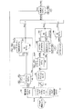
(Pm1の求め方)
図7に示したように、吸気管圧力Pm1は電子制御スロットルモデルM1、スロットルモデルM2、吸気弁モデルM3、及びインテークマニホールドモデルM4により推定される。
【0039】
(1)電子制御スロットルモデルM1
電子制御スロットルモデルM1は、現時点までのアクセルペダル操作量Accpに基づいて吸気弁閉時のスロットルバルブ開度TASを推定するモデルである。本実施形態においては、スロットルバルブ電子制御ロジックA1にて、アクセル開度センサ81により検出されたアクセルペダル操作量Accpと、図8に示したアクセルペダル操作量Accpと目標スロットルバルブ開度θrとの関係を規定するテーブルとに基づいて暫定的な目標スロットルバルブ開度θr1が求められ、この暫定的な目標スロットルバルブ開度θr1を所定時間T(例えば、64msec)だけ遅延させた値が最終的な目標スロットルバルブ開度θrとして決定される。そして、スロットルバルブ電子制御ロジックA1(電気制御装置70)は、実際のスロットルバルブ開度TAが目標スロットルバルブ開度θrとなるようにスロットルバルブアクチュエータ43aに対して駆動信号を送出する。
【0040】
このように、目標スロットルバルブ開度θrは、現時点から所定時間Tだけ前の時点におけるアクセルペダル操作量Accpに応じて決定されるから、現時点から吸気弁閉時までの時間をtとすると、吸気弁閉時の目標スロットルバルブ開度θrは、現時点から時間(T−t)前における暫定的な目標スロットルバルブ開度θr1と等しい。また、目標スロットルバルブ開度θrは、スロットルバルブアクチュエータ43aの作動遅れ時間を無視すれば、スロットルバルブ開度TASと等しい。このような考えに基づき、電子制御スロットルモデルM1は、検出されるエンジン回転速度Neと、内燃機関10の運転状態に応じて別途定められる吸気弁の開閉タイミング(進角量)VT(上記信号Neと上記G2信号とにより求めた実際の開閉タイミングVTでも良い。)と等に基づいて現時点から吸気弁閉時までの時間tを求め、同時間tと、現時点から所定時間Tだけ前の時点から現時点までのアクセルペダル操作量Accp(又は、暫定的な目標スロットルバルブ開度θr1)の変化の経緯とに基づいて吸気弁閉時のスロットルバルブ開度TASを推定する。なお、スロットルバルブアクチュエータ43aの作動遅れ時間を考慮に加えて、吸気弁閉時のスロットルバルブ開度TASを推定してもよい。
【0041】
(2)スロットルモデルM2
スロットルモデルM2は、スロットルバルブ43を通過する空気量(スロットル通過空気量)mtを、エネルギー保存則、運動量保存則、質量保存則、及び状態方程式に基づいて得られた下記数2及び下記数3に基づいて推定するモデルである。下記数2及び下記数3において、μは流量係数、Atはスロットル開口面積、νはスロットルバルブ43を通過する空気の流速、Paはスロットルバルブ上流圧力、Pmは吸気管圧力、Taは吸気温度、ρmは吸気密度、Rは気体定数、及びκは比熱比(以下、κを一定値として扱う。)である。
【0042】
【数2】
mt=μ・At・ν・ρm=μ・At・{Pa/(R・Ta)1/2}・Φ(Pm/Pa)
【0043】
【数3】

ここで、上記数2は、k1を所定の係数(=μ・At・{Pa/(R・Ta)1/2})、mtsを吸気弁閉時のスロットル通過空気量とするとき下記数4に書き換えられる。また、数4において、内燃機関10が定常状態にある場合(スロットルバルブ開度が一定である場合)のスロットル通過空気量をmtsTA、及び吸気管圧力をPmTAとすると、下記数5が得られるので、数4及び数5から係数k1を消去して下記数6を得ることができる。
【0045】
【数4】
mts=k1・Φ(Pm/Pa)
【0046】
【数5】
mtsTA=k1・Φ(PmTA/Pa)
【0047】
【数6】
mts={mtsTA/Φ(PmTA/Pa)}・Φ(Pm/Pa)
【0048】
上記数6の右辺における値{mtsTA/Φ(PmTA/Pa)}は、スロットルバルブ開度TAが一定であるときの吸入空気流量(スロットル通過空気量)に関する値であり、スロットルバルブ開度TA、エンジン回転速度Ne、吸気弁の開閉タイミングVT、及びスロットルバルブ上流圧力Paが決定されると、実質的に一意に定まる値である。スロットルモデルM2は、スロットルバルブ開度TA、エンジン回転速度Ne、吸気弁の開閉タイミングVT、及びスロットルバルブ上流圧力Paと、値{mtsTA/Φ(PmTA/Pa)}との関係を規定したテーブルをROM72内に記憶していて、このテーブルと吸気弁閉時の推定スロットルバルブ開度TAS、実際のエンジン回転速度Ne、実際の吸気弁の開閉タイミングVT、及び実際のスロットルバルブ上流圧力Paとに基づいて値{mtsTA/Φ(PmTA/Pa)}を求める。
【0049】
また、数6の右辺における値Φ(Pm/Pa)は、上記数3から理解されるように、比熱比κが一定であるとき、吸気管圧力Pmとスロットルバルブ上流圧力Paにより決定される値である。スロットルモデルM2は、吸気管圧力Pm及びスロットルバルブ上流圧力Paと、値Φ(Pm/Pa)との関係を規定したテーブルをROM72内に記憶していて、このテーブルと、後述するインテークマニホールドモデルM4が現時点で既に演算している最新の吸気管圧力Pm、及び実際のスロットルバルブ上流圧力Paとに基づいて値Φ(Pm/Pa)を求める。以上により、吸気弁閉時のスロットル通過空気量mtsが求められる。
【0050】
(3)吸気弁モデルM3
吸気弁モデルM3は、吸気管圧力Pm、吸気管内温度Tm、及び吸気温度THA等から筒内吸入空気流量mcを推定するモデルである。吸気弁閉弁時の気筒内圧力は吸気弁32の上流の圧力、即ち吸気弁閉時の吸気管圧力Pmとみなすことができるので、筒内吸入空気流量mcは吸気弁閉時の吸気管圧力Pmに比例する。そこで、吸気弁モデルM3は筒内吸入空気流量mcを、経験則に基づく下記数7にしたがって求める。
【0051】
【数7】
mc=(THA/Tm)・(c・Pm−d)
【0052】
数7において、値cは比例係数、値dは筒内に残存していた既燃ガス量である。吸気弁モデルM3は、エンジン回転速度Ne、及び吸気弁の開閉タイミングVTと、比例係数c、及び既燃ガス量dとの関係をそれぞれ規定するテーブルをROM72内に格納していて、実際のエンジン回転速度Neと、実際の吸気弁の開閉タイミングVTと前記格納しているテーブルとから比例係数c、及び既燃ガス量dを求める。また、吸気弁モデルM3は、演算時点において、後述するインテークマニホールドモデルM4により既に推定されている直前(最新)の吸気弁閉時の吸気管圧力Pmと直前の吸気管内空気温度Tmとを上記数7に適用し、吸気弁閉時の筒内吸入空気流量mcを推定する。
【0053】
(4)インテークマニホールドモデルM4
インテークマニホールドモデルM4は、質量保存則とエネルギー保存則とにそれぞれ基づいた下記数8及び下記数9にしたがって、吸気弁閉時の吸気管圧力Pmと、吸気弁閉時の吸気管内温度Tmとを求める。なお、Vは吸気管の容積、Rは気体定数、mtはスロットル通過空気量、Taはスロットルバルブ通過空気温度(即ち、吸気温度THA)である。
【0054】
【数8】
dPm/dt=κ・(R/V)・(mt・Ta−mc・Tm)
【0055】
【数9】
d(Pm/Tm)/dt=(R/V)・(mt−mc)
【0056】
図7に示したように、インテークマニホールドモデルM4は、スロットルモデルM2により推定されたスロットル通過空気量mtsを上記数8,数9におけるスロットル通過空気量mtとして使用し、吸気弁モデルM3により推定された吸気弁閉時の筒内吸入空気流量mcを上記数8,数9の筒内吸入空気流量mcとして使用する。このインテークマニホールドモデルM4により推定された吸気管圧力Pmが、前記吸気弁閉時の推定吸気管圧力Pm1となる。
【0057】
(Pm2の求め方)
上記エアフローメータ61が現時点で出力するであろう値に基づく吸気管圧力Pm2は、上記スロットルモデルM2と同じモデルであるスロットルモデルM5、エアフローメータモデルM6、上記吸気弁モデルM3と同じ吸気弁モデルM7、及び上記インテークマニホールドモデルM4と同じインテークマニホールドモデルM8により求められる。
【0058】
(5)スロットルモデルM5
具体的に述べると、スロットルモデルM5は、上記数6を書換えた下記数10に従って、現時点におけるスロットル通過空気量mtTHRを推定する。
【0059】
【数10】
mtTHR={mtsTA/Φ(PmTA/Pa)}・Φ(Pm/Pa)
【0060】
スロットルモデルM5は、上記数10の右辺における値{mtsTA/Φ(PmTA/Pa)}を、スロットルバルブ開度TA、エンジン回転速度Ne、吸気弁の開閉タイミングVT、及びスロットルバルブ上流圧力Paと、値{mtsTA/Φ(PmTA/Pa)}との関係を規定した前記テーブルと、スロットルポジションセンサ64が実際に検出したスロットルバルブ開度TA(以下、「実スロットルバルブ開度TAR」と称呼する。)、実際のエンジン回転速度Ne、実際の又は計算された吸気弁の開閉タイミングVT、及び実際のスロットルバルブ上流圧力Paとに基づいて求める。
【0061】
また、スロットルモデルM5は、数10の右辺における値Φ(Pm/Pa)を、吸気管圧力Pm及びスロットルバルブ上流圧力Paと値Φ(Pm/Pa)との関係を規定した前記テーブルと、後述するインテークマニホールドモデルM8が既に計算している最新の吸気管圧力PmR、及び実際のスロットルバルブ上流圧力Paとに基づいて求める。以上により、現時点におけるスロットル通過空気量mtTHRが求められる。
【0062】
(6)エアフローメータモデルM6
エアフローメータモデルM6は、スロットル通過空気量が所定の量αである場合に、エアフローメータ61が出力するであろう値を推定し、この推定値に基づいてスロットル通過空気量mtRを推定するモデルである。この場合、上記所定の量αは、スロットルモデルM5が推定したスロットル通過空気量mtTHRである。
【0063】
エアフローメータモデルM6は、先ず、スロットル通過空気量mtTHRに対する完全放熱量W1,W2を、同完全放熱量W1,W2とスロットル通過空気量mtとの関係を規定するテーブルと、前記求められたスロットル通過空気量mtTHRとに基づいて求める。完全放熱量W1、及び完全放熱量W2は、図4に示した熱線計量部61aのボビン部61a1、及び同熱線計量部61aのサポート部61a2にそれぞれ対応した放熱遅れを含まない放熱量である。
【0064】
次に、エアフローメータモデルM6は、ボビン部61a1、及びサポート部61a2にそれぞれ対応する放熱量であり、完全放熱量W1,W2に対してそれぞれ一次遅れの特性を有する応答遅れを含む放熱量(応答放熱量)w1,w2を下記数11及び下記数12にしたがって求める。数11,数12における添え字iは今回の演算値、添え字i−1は前回の演算値を表し、Δtは前回の演算値を求めてから今回の演算値を求めるまでの時間である。
【0065】
【数11】
w1i=Δt・(W1i−w1i-1)/τ1+w1i-1
【0066】
【数12】
w2i=Δt・(W2i−w2i-1)/τ2+w2i-1
【0067】
上記数11,数12において、τ1、及びτ2は、ボビン部61a1、及びサポート部61a2にそれぞれ対応する上記一次遅れ特性の時定数であり、下記数13及び下記数14により求められる。数13,数14中の値k10,k20、及び値m1,m2は、実験的に求められた値である。また、値uはエアフローメータ61の熱線計量部61aにバイパスされた単位断面積当たりの通過空気量であり、図5に示したエアフローメータ61の出力電圧Vgと実測された吸入空気量mtAFMとの関係を規定するVg−mtAFM変換テーブルと、エアフローメータ61の実際の出力電圧Vgとに基づいて求められた吸入空気量mtAFMを、前記熱線計量部61aのバイパス流路断面積Sで除した値(mtAFM/S)である。
【0068】
【数13】
τ1=k10・um1
【0069】
【数14】
τ2=k20・um2
【0070】
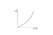
そして、エアフローメータモデルM6は、応答放熱量w1,w2の和(w1+w2)とエアフローメータ61が出力するであろう値に基づくスロットル通過空気量mtRとの関係を規定した図9に示したテーブルと、上記数11〜数14により求められた応答放熱量w1,w2の和(w1+w2)とに基づいて、現時点でエアフローメータ61が出力するであろう値に基づくスロットル通過空気量mtRを求める。
【0071】
(7)吸気弁モデルM7
吸気弁モデルM7は、上記吸気弁モデルM3と同様に、上記数7にしたがって現時点における筒内吸入空気流量mcRを求める。但し、吸気弁モデルM7は、後述するインテークマニホールドモデルM8により既に求めらている現時点の吸気管圧力PmR、及び現時点の吸気管内温度TmRを、上記数7における吸気管圧力Pm、及び吸気管内温度Tmに適用する等、必要なパラメータを全て現時点のものとして数7の計算を行う。
【0072】
(8)インテークマニホールドモデルM8
インテークマニホールドモデルM8は、インテークマニホールドモデルM4と同様に、上記数8,数9を用いて現時点における吸気管圧力Pmを求める。但し、インテークマニホールドモデルM8は、上記エアフローメータモデルM6により求められたスロットル通過空気量mtR、及び上記吸気弁モデルM7により求められた現時点における筒内吸入空気流量mcRを、それぞれ数8,数9におけるスロットル通過空気量mt、及び筒内吸入空気流量mcとして使用する。このインテークマニホールドモデルM8により推定されたPmが、前記エアフローメータ61が現時点で出力するであろう値に基づく吸気管圧力Pm2となる。
【0073】
(Pm3の求め方)
上記エアフローメータ61の現時点における実際の出力電圧Vgに基づく吸気管圧力Pm3は、上記インテークマニホールドモデルM4,M8と同じモデルであるインテークマニホールドモデルM9により求められる。
【0074】
(9)インテークマニホールドモデルM9
具体的に述べると、インテークマニホールドモデルM9は、エアフローメータ61の出力電圧Vgと図5に示したVg−mtAFM変換テーブルとにより求められる現時点の実測された吸入空気量mtAFMを上記数8,数9におけるスロットル通過空気量mtとして使用するとともに、上記吸気弁モデルM7により求められた現時点での筒内吸入空気流量mcRを同数8,数9の筒内吸入空気流量mcとして使用し、吸気管圧力Pmを求める。このインテークマニホールドモデルM9により推定された吸気管圧力Pmが、エアフローメータ61の現時点における実際の出力電圧Vgに基づく吸気管圧力Pm3となる。以上により、吸気管圧力Pm1〜Pm3が求められ、本制御装置は、上記数1にしたがって吸気弁閉時の吸気管圧力PMFWDを予測・推定するとともに、推定した吸気管圧力PMFWDに基いて一気筒当たりの吸入空気量相当値KLFWDを求める。
【0075】
(各燃料成分の燃料付着量及び各燃料成分の筒内流入燃料量の推定方法の概要)次に、本制御装置が行う、燃料を構成する燃料成分毎の燃料付着量の推定方法、同燃料成分毎のシリンダ内(筒内)流入燃料量の推定方法の概要について説明する。図10に概念的に示したように、インジェクタ39から噴射された燃料は、その一部が吸気管41の壁面部、及び図10において図示を省略した吸気弁等からなる吸気通路構成部材に付着する。
【0076】
このように吸気通路構成部材に付着した燃料は、先に説明したように、蒸留性状(沸点、飽和蒸気圧)の異なる多数の燃料成分から構成される混合物である。しかし、本実施形態の制御装置は、計算の簡便化によるCPU71の計算負担の軽減等の観点から、この燃料を、以下に説明する低沸点成分と高沸点成分との2つの燃料成分に二分し、これら2つの燃料成分から構成されているものとして扱う。
【0077】
図11は、吸気管41の温度(吸気管41の壁面温度、吸気通路内の温度。この温度は冷却水温THWで代用することができる。)が内燃機関10が完全に暖機した状態において発生し得る所定温度T0に維持されていて、且つ内燃機関10が定常状態にあるものとした場合における、吸気管圧力PMFWDと、吸気通路構成部材への低沸点成分の燃料付着量fwv及び吸気通路構成部材への高沸点成分の燃料付着量fwpとの関係をそれぞれ示したグラフである。
【0078】
図11から理解できるように、低沸点成分は、飽和蒸気圧が比較的高いことから、前記所定温度T0において吸気管圧力PMFWDが内燃機関10の運転中において発生し得る範囲内における或る所定圧力P0を下回ると吸気通路構成部材に付着していた燃料付着量fwvの燃料の全量が蒸発して燃料付着量fwvが「0」になるような、炭素数が少なくて沸点が低い燃料成分の群を総称したものである。一方、高沸点成分は、飽和蒸気圧が比較的低いことから、前記所定温度T0において吸気管圧力PMFWDが内燃機関10の運転中において発生し得る範囲内にあるときには常に吸気通路構成部材に付着する燃料付着量fwpの燃料が存在し得るような、炭素数が比較的多くて沸点が比較的高い燃料成分の群を総称したものである。
【0079】
このように、吸気通路構成部材に付着する低沸点成分の挙動は、吸気通路構成部材に付着する高沸点成分の挙動と大きく相違する。換言すると、一般に、燃料付着モデルで使用される燃料の付着率と残留率は、低沸点成分に対するものと高沸点成分に対するものとで大きく相違する。従って、本制御装置は、燃料付着モデルを、吸気通路構成部材に付着する低沸点成分についてのモデルと、吸気通路構成部材に付着する高沸点成分についてのモデルとで独立させ、付着率及び残留率をそれぞれに対して設定することにより、吸気通路構成部材への低沸点成分の燃料付着量fwvと吸気通路構成部材への高沸点成分の燃料付着量fwpとを分けて求める。
【0080】
より具体的に述べると、特定の気筒に着目した図12に示したように、fiをインジェクタ39から同特定気筒の一吸気行程に対して噴射される燃料噴射量、fwpを吸気通路構成部材にすでに付着している高沸点成分の燃料付着量、Ppを吸気通路構成部材にすでに付着している高沸点成分のうち一吸気行程を経た後に同吸気通路構成部材に付着したまま残留している高沸点成分の割合(高沸点成分の残留率Pp)、Rpをインジェクタ39から噴射された前記燃料のうち吸気通路構成部材へ付着する高沸点成分の割合(高沸点成分の付着率Rp)、添え字kを今回の演算値(今回の吸気行程に対する値)、添え字k+1は次回の演算値(次回の吸気行程に対する値)とすると、今回噴射された燃料のうち吸気通路構成部材に新たに付着する高沸点成分の量はRp・fi(k)であり、吸気通路構成部材にすでに付着していた高沸点成分のうち同吸気通路構成部材に残留する高沸点成分の量はPp・fw(k)であるから、高沸点成分の燃料付着量fwp(k+1)について下記数15が成立する。下記数15は、高沸点成分についての燃料付着モデルを記述したものである。
【0081】
【数15】
fwp(k+1)=Rp・fi(k)+Pp・fwp(k)
【0082】
同様に、fwvを吸気通路構成部材にすでに付着している低沸点成分の燃料付着量、Pvを吸気通路構成部材にすでに付着している低沸点成分のうち一吸気行程を経た後に同吸気通路構成部材に付着したまま残留している低沸点成分の割合(低沸点成分の残留率Pv)、Rvをインジェクタ39から噴射された前記燃料のうち吸気通路構成部材へ付着する低沸点成分の割合(低沸点成分の付着率Rv)とすると、今回噴射された燃料のうち吸気通路構成部材に新たに付着する低沸点成分の量はRv・fi(k)であり、吸気通路構成部材にすでに付着していた低沸点成分のうち同吸気通路構成部材に残留する低沸点成分の量はPv・fw(k)であるから、低沸点成分の燃料付着量fwv(k+1)について下記数16が成立する。下記数16は、低沸点成分についての燃料付着モデルを記述したものである。上記数15及び下記数16の演算を行う手段が燃料付着量推定手段に相当する。
【0083】
【数16】
fwv(k+1)=Rv・fi(k)+Pv・fwv(k)
【0084】
ここで、上記高沸点成分の付着率Rpは、噴射された前記燃料中の高沸点成分の割合Kpと噴射された高沸点成分のうち吸気通路構成部材へ付着する高沸点成分の割合R’pとの積であり、上記低沸点成分の付着率Rvは、噴射された前記燃料中の低沸点成分の割合Kvと噴射された低沸点成分のうち吸気通路構成部材へ付着する低沸点成分の割合R’vとの積である。前記燃料中の高沸点成分の割合Kpと前記燃料中の低沸点成分の割合Kv(Kp+Kv=1)は使用される燃料自体に依存し、本実施例では、前記燃料中の高沸点成分の割合Kpと前記燃料中の低沸点成分の割合Kvとをそれぞれ一定値として扱う。
【0085】
また、上記数15又は数16にて使用される上記高沸点成分の残留率Pp、低沸点成分の残留率Pv、高沸点成分の付着率Rp、及び低沸点成分の付着率Rvは、SCV開度センサ65により検出されるSCV開度θiv、クランクポジションセンサ67の出力に基くエンジン回転速度Ne、水温センサ68により検出される冷却水温THW、及び上記数1により計算されている最新の吸気弁閉時の吸気管圧力PMFWDの関数Fpp、関数Fpv、関数Frp、及び関数Frvにそれぞれ基く所定のテーブルにより決定される。
【0086】
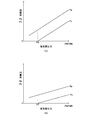
図13(a)は、前記所定のテーブルにおいて、SCV開度θiv、及びエンジン回転速度Neがそれぞれ所定の一定値に維持されていて、且つ冷却水温THWが前記所定温度T0に維持されているものと仮定した場合における、吸気管圧力PMFWDと、高沸点成分の残留率Pp及び低沸点成分の残留率Pvとの関係をそれぞれ示したグラフである。また、図13(b)は、図13(a)において仮定した場合(条件)と同一の場合における、吸気管圧力PMFWDと、高沸点成分の付着率Rp及び低沸点成分の付着率Rvとの関係をそれぞれ示したグラフである。
【0087】
図13(a)及び図13(b)に示したように、上記高沸点成分の残留率Pp、低沸点成分の残留率Pv、高沸点成分の付着率Rp、及び低沸点成分の付着率Rvは全て、吸気管圧力PMFWDが高くなるほど大きくなる。これは、吸気管圧力PMFWDが高くなるほど高沸点成分及び低沸点成分の各々の沸点が高くなり、その結果、吸気通路構成部材に付着していた高沸点成分及び低沸点成分の蒸発が抑制され、且つ、インジェクタ39から噴射された高沸点成分及び低沸点成分の霧化が抑制されることに基く。
【0088】
また、吸気管圧力PMFWDが内燃機関10の運転中において発生し得る範囲内にある状態においては、高沸点成分の残留率Ppは低沸点成分の残留率Pvよりも大きく、且つ、高沸点成分の付着率Rpは低沸点成分の付着率Rvよりも大きい。これは、同一条件下においては高沸点成分の沸点が低沸点成分の沸点よりも高く、その結果、高沸点成分の方が低沸点成分よりも、付着していた吸気通路構成部材からの蒸発が抑制され、且つ、インジェクタ39から噴射されたときの霧化が抑制されることに基く。
【0089】
また、低沸点成分の残留率Pv及び低沸点成分の付着率Rvは共に、吸気管圧力PMFWDが前記所定圧力P0を下回ると「0」になる。これは、先に図11を参照しつつ説明したように、冷却水温THWが前記所定温度T0に維持されている場合、吸気管圧力PMFWDが前記所定圧力P0を下回ると低沸点成分が吸気通路構成部材に付着し得なくなることに基く。
【0090】
次に、本制御装置は、上述したように高沸点成分についての燃料付着モデルを利用して求めた吸気通路構成部材への高沸点成分の燃料付着量fwpと低沸点成分についての燃料付着モデルを利用して求めた吸気通路構成部材への低沸点成分の燃料付着量fwvとに基いて、高沸点成分の筒内流入燃料量fcpと低沸点成分の筒内流入燃料量fcvとを分けて求める。
【0091】
即ち、一吸気行程において、今回噴射された燃料噴射量fi(k)の燃料のうち吸気通路構成部材に付着せず筒内に直接吸入される高沸点成分の量はKp・(1-R’p)・fi(k)=(Kp-Rp)・fi(k)となり、吸気通路構成部材に付着していた高沸点成分のうち同吸気通路構成部材から離脱して筒内に吸入される高沸点成分の量は(1-Pp)・fwp(k)となるから、筒内に吸入される高沸点成分の筒内流入燃料量fcp(k)は下記数17により表すことができる。
【0092】
【数17】
fcp(k)=(1-Pp)・fwp(k)+(Kp-Rp)・fi(k)
【0093】
同様に、一吸気行程において、今回噴射された燃料噴射量fi(k)の燃料のうち吸気通路構成部材に付着せず筒内に直接吸入される低沸点成分の量はKv・(1-R’v)・fi(k)=(Kv-Rv)・fi(k)となり、吸気通路構成部材に付着していた低沸点成分のうち同吸気通路構成部材から離脱して筒内に吸入される低沸点成分の量は(1-Pv)・fwv(k)となるから、筒内に吸入される低沸点成分の筒内流入燃料量fcv(k)は下記数18により表すことができる。上記数17及び下記数18の演算を行う手段が筒内流入燃料量推定手段に相当する。
【0094】
【数18】
fcv(k)=(1-Pv)・fwv(k)+(Kv-Rv)・fi(k)
【0095】
以上のように、本実施形態の制御装置は、高沸点成分についての燃料付着モデルと低沸点成分についての燃料付着モデルを利用して、吸気通路構成部材への高沸点成分の燃料付着量fwpと吸気通路構成部材への低沸点成分の燃料付着量fwvとを分けて求めるとともに、吸気通路構成部材への高沸点成分の燃料付着量fwpと吸気通路構成部材への低沸点成分の燃料付着量fwvとに基いて、高沸点成分の筒内流入燃料量fcpと低沸点成分の筒内流入燃料量fcvとを分けて求める。
【0096】
(点火時期の決定方法の概要)
一般に、上記低沸点成分はオクタン価が低く、上記高沸点成分は同低沸点成分よりもオクタン価が高い。従って、筒内に流入する(筒内で実際に燃焼される)燃料全体としてのオクタン価(筒内オクタン価)は、筒内に流入する低沸点成分に対する筒内に流入する高沸点成分の比率に応じて変化し、同比率が大きくなるほど筒内オクタン価は高くなる。よって、前記比率の増加に応じて内燃機関10の点火時期を進角側に移動することが好ましい。ここで、前記筒内に流入する低沸点成分に対する筒内に流入する高沸点成分の比率(以下、「成分比率」と称呼する。)RATIOは、上記数17及び数18に基き、下記数19により表すことができる。
【0097】
【数19】
RATIO=fcp(k)/fcv(k)=((1-Pp)・fwp(k)+(Kp-Rp)・fi(k))/((1-Pv)・fwv(k)+(Kv-Rv)・fi(k))
【0098】
上記数19において使用されている高沸点成分の残留率Pp、低沸点成分の残留率Pv、高沸点成分の付着率Rp、及び低沸点成分の付着率Rvは、先に図13等を参照しつつ説明したように吸気弁閉時の吸気管圧力PMFWD等が変化すると互いに独立して変化する。従って、内燃機関10の運転状態が過渡運転状態にあるときには、成分比率RATIOの値は時々刻々と変化する。
【0099】
一方、内燃機関10の運転状態が定常状態にあるときには、吸気通路構成部材への高沸点成分の燃料付着量fwpも吸気通路構成部材への低沸点成分の燃料付着量fwvも時間的に変化しない状態となっている。従って、上記数15においてfwp(k+1)をfwp(k)と置き、上記数16においてfwv(k+1)をfwv(k)と置くと、それぞれ、下記数20及び数21を得ることができる。
【0100】
【数20】
fwp(k)=(Rp/(1-Pp))・fi(k)
【0101】
【数21】
fwv(k)=(Rv/(1-Pv))・fi(k)
【0102】
上記数19〜数21から高沸点成分の燃料付着量fwp(k)及び低沸点成分の燃料付着量fwv(k)を消去して数19を整理すると、内燃機関10が定常状態にあるときにおける筒内に流入する低沸点成分に対する筒内に流入する高沸点成分の比率(以下、「定常状態時成分比率」と称呼する。)RATIOsteadyが得られ、定常状態時成分比率RATIOsteadyは、下記数22により表すことができる。
【0103】
【数22】
RATIOsteady=Kp/Kv
【0104】
先に述べたように、前記燃料中の高沸点成分の割合Kpと前記燃料中の低沸点成分の割合Kvはそれぞれ一定値である。従って、前記成分比率RATIOの値は、内燃機関10が定常状態にある限りにおいて一定値である定常状態時成分比率RATIOsteadyとなる。なお、上記数22にて示される定常状態時成分比率RATIOsteadyの値は、内燃機関10に使用されている燃料自体の低沸点成分に対する高沸点成分の比率と等しい。従って、内燃機関10が定常状態にあるときの筒内オクタン価は、燃料自体のオクタン価と等しいことになる。
【0105】
ここで、先に説明したように、本制御装置がROM72に格納している上述した基本点火時期テーブルにより求められる基本点火時期ITsteadyは、内燃機関10が定常状態にあるときに最適な燃焼状態が得られるように決定されている。従って、基本点火時期ITsteadyは、筒内に流入する低沸点成分に対する筒内に流入する高沸点成分の比率が上記定常状態時成分比率RATIOsteadyと等しいときに最適な燃焼状態が得られるように決定されていることになる。
【0106】
よって、内燃機関10が過渡状態にあって、上記数19に基く成分比率RATIOの値が上記定常状態時成分比率RATIOsteadyより大きいときは、内燃機関10の点火時期を基本点火時期ITsteadyよりも進角側に補正し、成分比率RATIOの値が定常状態時成分比率RATIOsteadyより小さいときは、同点火時期を基本点火時期ITsteadyよりも遅角側に補正することが好ましい。
【0107】
そこで、本実施形態の制御装置は、内燃機関10の点火時期ITを求めるため、先ず、成分比率RATIOと定常状態時成分比率RATIOsteadyとの大小関係の程度を示す指標値として、下記数23により比率比XRを求める。
【0108】
【数23】
XR=RATIO/RATIOsteady
【0109】
次に、本制御装置は、比率比XRと点火時期補正量ΔITとの関係を規定する図14にグラフにより示したテーブルと、同比率比XRとに基いて点火時期補正量ΔITを決定する。これにより、点火時期補正量ΔITは、比率比XRが「1」より大きいとき、比率比XRの増加に応じて増大し(より進角側に補正する正の量となり)、比率比XRが「1」より小さいとき、比率比XRの減少に応じて減少する(より遅角側に補正する負の量となる)。換言すれば、点火時期補正量ΔITは、成分比率RATIOと定常状態時成分比率RATIOsteadyとの相違の程度に応じて決定される。
【0110】
そして、本制御装置は、下記数24に基いて機関制御パラメータとしての内燃機関10の点火時期ITを求める。下記数24により点火時期ITを決定する手段が機関制御パラメータ決定手段を構成する。
【0111】
【数24】
IT=ITsteady+ΔIT
【0112】
このようにして、本制御装置は、上記数17及び数18により求められた高沸点成分の筒内流入燃料量fcpと低沸点成分の筒内流入燃料量fcvとに基いて基本点火時期ITsteadyを点火時期補正量ΔITだけ補正することで、内燃機関10の点火時期ITを求める。
【0113】
(点火時期制御の一例)
図15は、内燃機関10が定常状態から急減速運転された場合における上記数1により計算される吸気管圧力PMFWD、比率比XR、及び点火時期補正量ΔITの変化の一例を示したタイムチャートである。先ず、このタイムチャートにおいては、時刻t1になるまで、内燃機関10は、吸気管41の温度(冷却水温THW)が前記所定温度T0に近い温度になっていて、且つ、スロットルバルブ開度TAが比較的大きい一定値に維持されていることで吸気管圧力PMFWDが前記所定圧力P0よりも大きい一定値となる、定常状態にある。
【0114】
この定常状態では、上述したように成分比率RATIOの値は定常状態時成分比率RATIOsteadyと等しいので、図15(b)に示すように、比率比XRは「1」に維持され、この結果、図15(c)に示すように、点火時期補正量ΔITは「0」に維持されている。
【0115】
そして、時刻t1になると、運転者が、アクセルペダル82の操作量Accpが急激に所定量だけ減少した後その時点での同操作量Accpに維持されるようにアクセルペダル82を操作したものとする。これにより、スロットルバルブ開度TAも時刻t1以降、急減した後に一定値に維持される。その結果、図15(a)に示すように、吸気管圧力PMFWDも、時刻t1以降、前記所定圧力よりも大きい一定値から急減を開始するとともに、時刻t2になると、前記所定圧力P0よりも小さい一定値に維持されて、内燃機関10は再び定常状態となる。
【0116】
このように、時刻t1から時刻t2までの過渡運転状態の間に吸気管圧力PMFWDが急激に減少すると、先に説明した図13のグラフ、及び成分比率RATIOを計算する上記数19から理解できるように、上記低沸点成分の残留率Pv、及び低沸点成分の付着率Rvが共に直ちに「0」になって、成分比率RATIOが一時的に定常状態時成分比率RATIOsteadyよりも小さくなる。
【0117】
その結果、図15(b)に示すように、時刻t1から時刻t2の間、比率比XRが一時的に「1」よりも小さくなるとともに、図15(c)に示すように、点火時期補正量ΔITも一時的に負の値(点火時期を遅角側に補正する量)になる。そして、時刻t2以降、内燃機関10が定常状態に復帰したことにより、比率比XRは「1」に維持されるとともに、点火時期補正量ΔITは「0」に維持される。
【0118】
従って、図15に示すタイムチャートにおいては、本制御装置は、点火時期ITを、時刻t1になるまでは基本点火時期ITsteadyになるように、時刻t1以降時刻t2までの過渡運転状態においては基本点火時期ITsteadyよりも図15(c)に示す点火時期補正量ΔITだけ遅角側に補正した時期になるように、時刻t2以降は再び基本点火時期ITsteadyになるように制御する。
【0119】
(実際の作動)
以下、上記内燃機関の制御装置の作動について、CPU71が実行するルーチン(プログラム)をフローチャートにより示した図16〜図19を参照しながら説明する。
【0120】
(スロットルバルブ制御)
CPU71は、図16のスロットルバルブ制御ルーチンの処理を所定時間(2msec)の経過毎にステップ1600から開始し、ステップ1605に進んでアクセルペダル操作量Accpを読み込む。次いで、CPU71はステップ1610に進み、同ステップ1610にて図8と同じテーブルを用いることにより上記読み込んだアクセルペダル操作量Accpに基づく暫定的な目標スロットルバルブ開度θr1を求める。
【0121】
次に、CPU71はステップ1615に進んで変数Iを「64」に設定し、続くステップ1620にて記憶値θr(I)にθr(I−2)の値を格納する。現時点では、変数Iは「64」であるから、記憶値θr(64)に記憶値θr(62)の値が格納される。次いで、CPU71はステップ1625に進み、変数Iが「2」と等しくなったか否かを判定する。この場合、変数Iの値は「64」であるから、CPU71はステップ1625にて「No」と判定してステップ1630に進み、同ステップ1630にて変数Iの値を「2」だけ減少し、その後上記ステップ1620に戻る。この結果、ステップ1620が実行されると、記憶値θr(62)に記憶値θr(60)の値が格納される。このような処理は、変数Iの値が「2」となるまで繰り返し実行される。
【0122】
その後、ステップ1630の処理が繰り返されて変数Iの値が「2」となると、CPU71はステップ1625にて「Yes」と判定してステップ1635に進み、同ステップ1635にて前記ステップ1610にて求めた現時点における暫定的な目標スロットルバルブ開度θr1を記憶値θr(0)に格納する。以上により、現時点からImsec前(0msec≦Imsec≦64msec)の暫定的な目標スロットルバルブ開度θr(I)(I=64,62,・・・,4,2,0)がRAM73内に記憶されることになる。
【0123】
次に、CPU71はステップ1640に進み、同ステップ1640にて記憶値θr(64)を最終的な目標スロットルバルブ開度θrとして設定し、続くステップ1645にて実際のスロットルバルブ開度が目標スロットルバルブ開度θrと等しくなるように、スロットルバルブアクチュエータ43aに対し駆動信号を出力し、その後ステップ1695にて本ルーチンを一旦終了する。
【0124】
以降においても、上記ルーチンの処理は2msecの経過毎に実行される。この結果、実際のスロットルバルブ開度が、64msec前のアクセルペダル操作量Accpに基づく目標スロットルバルブ開度θrと等しくなるように制御される。これにより、上記電子制御スロットルモデルM1による吸気弁閉時のスロットルバルブ開度TASの推定が可能となる。
【0125】
(吸気弁開閉タイミング制御、及びSCV開度制御)
CPU71は、図17の吸気弁開閉タイミング・SCV開度制御ルーチンを所定時間(例えば、2msec)の経過毎にステップ1700から開始し、ステップ1705に進んクランクポジションセンサ67の出力に基づくエンジン回転速度Neを読み込むとともに、ステップ1710にて前述した筒内吸入空気量に相当する値KLFWD(即ち、エンジン負荷)を読込む。なお、筒内吸入空気量に相当する値KLFWDは、所定時間毎に繰り返し実行される前述した吸入空気量相当値の決定方法(図7に示したモデル)に従う図示しないルーチンにより求められている。
【0126】
次に、CPU71はステップ1715に進み、同ステップ1715内に示したテーブルと上記読み込んだエンジン回転速度Ne及び筒内吸入空気量相当値KLFWDとに基づいて吸気弁の開閉タイミング(進角量)VTを決定し、続くステップ1720にて実際の進角量が前記決定した進角量VTとなるように、アクチュエータ33aに駆動信号を出力する。なお、ステップ1715に示したテーブルにおいては、VT1,VT2,VT3の順に進角量が大きくなるように設定されている。
【0127】
次いで、CPU71はステップ1725に進み、同ステップ1725内に示したテーブルと上記読み込んだエンジン回転速度Ne及び筒内吸入空気量相当値KLFWDとに基づいて目標SCV開度θivrを決定し、続くステップ1730にて実際のSCV開度が前記決定した目標SCV開度θivrとなるように、アクチュエータ44aに駆動信号を出力した後、ステップ1795に進んで本ルーチンを一旦終了する。なお、ステップ1725に示したテーブルにおいては、θ1,θ2,θ3の順に値が大きくなるように設定されている。
【0128】
以降においても、上記処理は2msecの経過毎に実行される。この結果、実際の吸気弁開閉タイミングの進角量と実際のSCV開度が、エンジン回転速度Neと筒内吸入空気量相当値KLFWDに応じた値に変更される。
【0129】
(燃料付着量の推定、及び燃料噴射制御)
CPU71は、特定気筒のクランク角が、その気筒の吸気上死点から所定クランク角度だけ前の角度(例えば、BTDC90°)になると、図18の燃料噴射制御ルーチンの処理をステップ1800から開始してステップ1805に進み、同ステップ1805にて、図7に示したモデルに従って別途計算されている上記吸気弁閉時の筒内吸入空気量に相当する値KLFWDと、下記数25とに基いて今回の要求燃料噴射量fc(k)を算出する。下記数25において、Kは設定空燃比に応じて変化する係数である。
【0130】
【数25】
fc(k)=K・KLFWD
【0131】
次いで、CPU71はステップ1810に進んで、SCV開度センサ65が検出するSCV開度θiv、クランクポジションセンサ67の出力に基づくエンジン回転速度Ne、水温センサ68が検出する冷却水温THW、及び上記筒内吸入空気量相当値KLFWDを推定する際に求めた吸気管圧力PMFWD等のパラメータ(以下、このパラメータを「引数パラメータ」と称呼する。)を読み込む。
【0132】
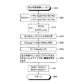
次に、CPU71はステップ1815に進んで、上記引数パラメータと、高沸点成分の付着率Rp、低沸点成分の付着率Rv、高沸点成分の残留率Pp、及び低沸点成分の残留率Pvとの関係をそれぞれ規定する予めROM72に記憶したテーブルと、上記ステップ1810にて読み込んだ引数パラメータとに基づき、現時点での高沸点成分の付着率Rp、低沸点成分の付着率Rv、高沸点成分の残留率Pp、及び低沸点成分の残留率Pvをそれぞれ決定する。
【0133】
次いで、CPU71はステップ1820に進み、下記数26を変形した得た同ステップ1820内に記載した式、上記ステップ1805にて求めた要求燃料噴射量fc(k)、及び上記ステップ1815にて決定した付着率Rp、付着率Rv、残留率Pp、及び残留率Pvに基づいて今回の燃料噴射量fi(k)を算出する。
【0134】
【数26】
fc(k)=(1-Pp)・fwp(k)+(1-Pv)・fwv(k)+(1-Rp-Rv)・fi(k)
【0135】
上記数26は、筒内流入燃料量(要求燃料噴射量)fc(k)が高沸点成分の筒内流入燃料量fcp(k)と低沸点成分の筒内流入燃料量fcv(k)の和であることに基く下記数27と、上記数17及び数18とから、高沸点成分の筒内流入燃料量fcp(k)と低沸点成分の筒内流入燃料量fcv(k)を消去して数27を整理し、同整理した後の式に、前記燃料中の高沸点成分の割合Kpと前記燃料中の低沸点成分の割合Kvとの関係を示す下記数28を適用することにより得ることができる。
【0136】
【数27】
fc(k)=fcp(k)+fcv(k)
【0137】
【数28】
Kp+Kv=1
【0138】
次に、CPU71はステップ1825に進み、上記数15にしたがって高沸点成分の燃料付着量fwp(k+1)を求めるとともに、続くステップ1830にて上記数16にしたがって低沸点成分の燃料付着量fwv(k+1)を求める。
【0139】
そして、CPU71はステップ1835に進んで、上記ステップ1820にて決定した今回の燃料噴射量fi(k)だけ燃料を噴射するように前記特定気筒に対するインジェクタ39に駆動信号を送出し、ステップ1895に進んで本ルーチンを一旦終了する。
【0140】
以上により、上記特定の気筒に対する燃料噴射量が、高沸点成分及び低沸点成分の各々の燃料付着量、従って高沸点成分及び低沸点成分の各々の筒内流入燃料量に基づいて決定され、同燃料噴射量の燃料が同特定気筒に対するインジェクタ39から噴射される。なお、CPU71は、他の気筒に対しても、図18のルーチンと同様なルーチンを同様なタイミングで実行する。
【0141】
(点火時期制御)
CPU71は、特定気筒のクランク角が、その気筒の圧縮上死点(爆発上死点)から所定クランク角度だけ前の角度(例えば、BTDC90°)になると、図19の点火時期制御ルーチンの処理をステップ1900から開始してステップ1905に進み、同ステップ1905にて、上記数19に基く同ステップ1905内に記載した式、図18のステップ1820にて求めた今回の燃料噴射量fi(k)、図18のステップ1815にて決定した高沸点成分の付着率Rp、低沸点成分の付着率Rv、高沸点成分の残留率Pp、及び低沸点成分の残留率Pv、並びに、前回本ルーチン実行時において後述するステップ1935にて更新(格納)されている高沸点成分の燃料付着量fwp(k)及び低沸点成分の燃料付着量fwv(k)に基づいて現時点での成分比率RATIOを算出する。
【0142】
次に、CPU71はステップ1910に進んで、前記ステップ1905にて算出した成分比率RATIOと前記定常状態時成分比率RATIOsteady(一定値)と、上記数23に相当するステップ1910内に記載の式とに基き比率比XRを求める。次いで、CPU71はステップ1915に進んで、図14のテーブルと、前記ステップ1910にて求めた比率比XRとに基き点火時期補正量ΔITを算出する。
【0143】
続いて、CPU71はステップ1920に進み、上記引数パラメータと、基本点火時期ITsteadyとの関係を規定する予めROM72に記憶した基本点火時期テーブルと、図18のステップ1810にて読み込んだ引数パラメータとに基づき、現時点での基本点火時期ITsteadyを決定する。
【0144】
次に、CPU71はステップ1925に進んで、前記ステップ1915にて算出した点火時期補正量ΔITと、前記ステップ1920にて決定した基本点火時期ITsteadyと、上記数24に相当するステップ1925内に記載の式とに基き現時点で最適な点火時期ITを算出する。
【0145】
そして、CPU71はステップ1930に進み、前記ステップ1925にて算出した点火時期ITにて上記特定気筒に対する点火プラグ37が点火するようにイグナイタ38に駆動信号を出力した後、続くステップ1935にて、図18のステップ1825にて求められている高沸点成分の燃料付着量fwp(k+1)、及び図18のステップ1830にて求められている低沸点成分の燃料付着量fwv(k+1)を、次回の演算のために、高沸点成分の燃料付着量fwp(k)、及び低沸点成分の燃料付着量fwv(k)にそれぞれ置き換え、ステップ1995に進んで、本ルーチンを一旦終了する。
【0146】
以上により、上記特定の気筒に対する最適な点火時期が、高沸点成分及び低沸点成分の各々の筒内流入燃料量に基づいて決定され、同特定気筒に対する点火プラグ37が前記決定された点火時期に点火する。なお、CPU71は、他の気筒に対しても、図19のルーチンと同様なルーチンを同様なタイミングで実行する。
【0147】
以上説明したように、本発明による内燃機関の制御装置の実施形態によれば、吸気通路構成部材に対する付着挙動が互いに相違する高沸点成分及び低沸点成分の各々の燃料付着量fwp(k),fwv(k)を区別して推定することにより、各燃料成分の吸気通路構成部材への燃料付着量fwp(k),fwv(k)がそれぞれ精度良く推定される。従って、前記推定された各燃料成分の燃料付着量fwp(k),fwv(k)に基いて燃焼室25内に流入する同各燃料成分の筒内流入燃料量fcp(k),fcv(k)が同燃料成分毎に区別して推定できるので、各燃料成分の筒内流入燃料量fcp(k),fcv(k)もそれぞれ精度良く推定される。この結果、内燃機関10が過渡運転状態にあるときでも、時々刻々と変化する筒内に流入する燃料の各燃料成分間の成分比率RATIOを精度良く求めることができる。そして、定常状態時成分比率RATIOsteady(一定値)に対する成分比率RATIOの比率である比率比XRに基き点火時期補正量ΔITを求め、定常運転時にて予め適合されている基本点火時期ITsteadyを点火時期補正量ΔITだけ補正することで点火時期ITが求められる。従って、内燃機関10が過渡運転状態にあるときでも、その運転状態を良好な状態に維持できるように点火時期ITを決定することができた。
【0148】
本発明は上記実施形態に限定されることはなく、本発明の範囲内において種々の変形例を採用することができる。例えば、上記実施形態では、使用される燃料を高沸点成分と低沸点成分の2つの燃料成分に分けているが、使用される燃料を蒸留性状(沸点、飽和蒸気圧)が異なる3つ以上の燃料成分に分けてもよい。
【0149】
また、上記実施形態では、成分比率RATIOに対する定常状態時成分比率RATIOsteadyの比率である比率比XRに基き点火時期補正量ΔITを求めているが、成分比率RATIOと定常状態時成分比率RATIOsteadyとの差に基き点火時期補正量ΔITを求めてもよい。
【図面の簡単な説明】
【図1】 本発明による内燃機関の制御装置を火花点火式多気筒内燃機関に適用したシステムの概略構成図である。
【図2】 図1に示した特定の気筒の燃焼室、及び同燃焼室の近傍部分を概念的に示した平面図である。
【図3】 図1に示したエアフローメータの概略斜視図である。
【図4】 図3に示したエアフローメータの熱線計量部の拡大斜視図である。
【図5】 図1に示したCPUが参照するエアフローメータの出力と吸入空気量(吸入空気流量)との関係を規定したテーブルを表したグラフである。
【図6】 吸気弁閉時の吸気管圧力を予測する方法を説明するために、スロットルバルブ開度の変化と各種のモデルにより計算される吸気管圧力の変化を示したタイムチャートである。
【図7】 図1に示した制御装置が吸気弁閉時の筒内吸入空気量に相当する値を推定するために採用した各種モデルの接続関係を示す機能ブロック図である。
【図8】 図1に示したCPUが参照するアクセルペダル操作量と目標スロットルバルブ開度との関係を規定したテーブルを表したグラフである。
【図9】 図1に示したCPUが参照する応答放熱量の和とエアフローメータが出力するであろう値に基づくスロットル通過空気量との関係を規定したテーブルを表したグラフである。
【図10】 図1に示した制御装置による燃料付着量の推定方法を説明するために、インジェクタから噴射された燃料が吸気通路に付着する様子を概念的に示した図である。
【図11】 図1に示した吸気管内の圧力と、高沸点成分と低沸点成分の各々の吸気通路構成部材への燃料付着量との関係を説明するための図である。
【図12】 図1に示したインジェクタから噴射された燃料量と、高沸点成分と低沸点成分の各々の吸気通路構成部材への燃料付着量、及び高沸点成分と低沸点成分の各々の筒内に流入する燃料量の関係を説明するための図である。
【図13】 図1に示したCPUが参照する、吸気管圧力と、高沸点成分及び低沸点成分の各々の残留率及び付着率との関係を規定したテーブルを表したグラフである。
【図14】 図1に示したCPUが参照する比率比と点火時期補正量との関係を規定したテーブルを表したグラフである。
【図15】 内燃機関が定常状態から急減速運転された場合における吸気管圧力、比率比、及び点火時期補正量の変化の一例を示したタイムチャートである。
【図16】 図1に示したCPUが実行するスロットルバルブ開度を制御するためのルーチンを示したフローチャートである。
【図17】 図1に示したCPUが実行する吸気弁開閉タイミング、及びSCV開度を制御するためのルーチンを示したフローチャートである。
【図18】 図1に示したCPUが実行する燃料噴射量を制御するためのルーチンを示したフローチャートである。
【図19】 図1に示したCPUが実行する点火時期を制御するためのルーチンを示したフローチャートである。
【符号の説明】
10…火花点火式多気筒内燃機関、20…シリンダブロック部(エンジン本体部)、25…燃焼室、31…吸気ポート、32…吸気弁、39…インジェクタ、41…吸気管、43…スロットルバルブ、70…電気制御装置、71…CPU。[0001]
BACKGROUND OF THE INVENTION
The present invention relates to a control device for an internal combustion engine, and more particularly to a control device that controls engine control parameters such as ignition timing so that the operating state of the internal combustion engine becomes good.
[0002]
[Prior art]
The knock limit of the internal combustion engine changes according to the octane number of the fuel (gasoline) used in the internal combustion engine, and the knock limit moves to the advance side as the octane number of the fuel used increases. Therefore, in order to obtain an optimal combustion state in the internal combustion engine, it is necessary to change the ignition timing according to the octane number of the fuel used. For this reason, the ignition timing control device for an internal combustion engine disclosed in
[0003]
[Patent Document 1]
Japanese Patent Laid-Open No. 5-79439
[0004]
[Problems to be solved by the invention]
By the way, a fuel (gasoline) widely used as a fuel for an internal combustion engine is a low boiling point component having a low carbon number and a low boiling point (for example, methane, ethane) or a high boiling point and a relatively high boiling point. It is a mixture composed of a plurality of fuel components having different distillation properties (boiling point, saturated vapor pressure) such as a boiling point component (for example, benzene). In general, the low boiling point component has a low octane number, and the high boiling point component has a higher octane number than the low boiling point component. In other words, the octane number of each fuel component having different distillation properties varies from fuel component to fuel component. Therefore, the octane number of the fuel (gasoline) itself (whole) which is a mixture changes in accordance with the octane number of each of the plurality of fuel components and the component ratio thereof.
[0005]
On the other hand, in an internal combustion engine provided with fuel injection means (injector) for injecting fuel into an intake passage connected to a combustion chamber, part of the fuel injected from the fuel injection means is an intake passage wall surface or an intake valve. It adheres to intake passage components such as At this time, the adhesion behavior of the fuel to the intake passage constituting member is different for each fuel component because the distillation property of each fuel component of the fuel is different. In particular, when the internal combustion engine is in a transient operation state and the pressure or temperature in the intake passage changes suddenly, the degree of vaporization or liquefaction among the fuel components changes abruptly. The adhesion behavior of the components becomes abruptly different among the fuel components. As a result, the component ratio between the fuel components flowing into the cylinder (inside the cylinder) temporarily changes, and the octane number (hereinafter, referred to as the whole fuel) flowing into the cylinder (actually burned in the cylinder) Also called “in-cylinder octane number”) temporarily changes from the octane number of the fuel itself used.
[0006]
Therefore, in the above-disclosed apparatus, even if the ignition timing is determined according to the octane number of the fuel (self) used, the in-cylinder octane number of the fuel flowing into the cylinder particularly in the transient operation state There is a problem that the optimal combustion state cannot be obtained because it temporarily changes from the octane number (when the determined ignition timing is not the optimal ignition timing).
[0007]
Therefore, an object of the present invention is to provide a control device for an internal combustion engine that can control engine control parameters such as ignition timing so that the operation state can be maintained in a good state even when the internal combustion engine is in a transient operation state. It is to provide.
[0008]
[Outline of the present invention]
A feature of the present invention is that an internal combustion engine control device applied to an internal combustion engine having fuel injection means for injecting fuel having a plurality of fuel components having different distillation properties into an intake passage connected to a combustion chamber, A fuel adhesion amount estimating means for estimating the fuel adhesion amount of each fuel component adhering to a member constituting the intake passage for each fuel component, and flowing into the combustion chamber based on the estimated fuel adhesion amount of each fuel component; In-cylinder inflow fuel amount estimating means for estimating the inflow in-cylinder amount of each fuel component for each fuel component, and the operating state of the internal combustion engine based on the in-cylinder inflow fuel amount of the estimated fuel component And an engine control parameter determining means for determining an engine control parameter for adjusting the engine to a good state.
[0009]
In this case, the members constituting the intake passage may include an intake pipe (intake manifold), an intake valve (particularly, the back surface of the intake valve), and an intake control valve such as an SCV provided in the intake passage. The engine control parameters include, for example, ignition timing, target air-fuel ratio, intake valve and exhaust valve opening / closing timing, and fuel injection timing, and are not limited thereto.
[0010]
Further, in the control device for an internal combustion engine, the fuel adhesion amount estimation means is determined for each fuel component of the fuel, and among the fuel components injected from the fuel injection means, The intake passage adhering rate of each fuel component representing the ratio of the adhering fuel components, and the intake passage of the fuel components determined for each fuel component of the fuel and adhering to the intake passage constituting member A fuel adhering amount of each fuel component adhering to the intake passage constituent member is estimated using an intake passage residual ratio of each fuel component representing a ratio of the fuel component remaining adhering to the constituent member. It is preferred that
[0011]
The fuel adhesion behavior (represented by, for example, a fuel adhesion model using an intake passage adhesion rate, an intake passage residual rate, etc.) to the intake passage constituent member differs for each of a plurality of fuel components having different distillation properties constituting the fuel. . Therefore, as described above, by estimating the fuel adhesion amount of each fuel component adhering to the intake passage constituent member separately for each fuel component, the fuel adhesion amount of each fuel component to the intake passage constituent member is respectively determined. Estimated with high accuracy.
[0012]
Further, according to the above configuration, the in-cylinder inflow fuel amount of each fuel component flowing into the combustion chamber is estimated separately for each fuel component based on the estimated fuel adhesion amount of each fuel component. The amount of fuel flowing into the cylinder of each fuel component is also estimated with high accuracy. Therefore, even when the internal combustion engine is in a transient operation state, for example, the component ratio between each fuel component of the fuel flowing into the cylinder (cylinder) that changes from moment to moment can be obtained with high accuracy. The in-cylinder octane number of the fuel flowing into the cylinder can be obtained with high accuracy.
[0013]
Therefore, as described above, by determining the engine control parameter for adjusting the operating state of the internal combustion engine to be in a good state based on the estimated in-cylinder inflow fuel amount of each fuel component, For example, the engine control parameters such as the ignition timing can be determined based on the component ratio (in-cylinder octane number of the fuel flowing into the cylinder) between the fuel components flowing into the cylinder that changes every moment. Therefore, even when the internal combustion engine is in a transient operation state, engine control parameters such as ignition timing can be controlled so that the operation state can be maintained in a good state.
[0014]
When the control device for the internal combustion engine includes basic ignition timing storage means for storing the basic ignition timing of the internal combustion engine in which the operation state is good when the operation state of the internal combustion engine is in a steady state. The engine control parameter determination means corrects the ignition timing of the internal combustion engine as the engine control parameter from the basic ignition timing based on the estimated in-cylinder fuel flow amount of each fuel component. It is desirable to be configured to determine.
[0015]
The optimum ignition timing in an internal combustion engine changes in accordance with a combination of a plurality of factors that affect the knock limit such as the engine speed, the intake air amount, and the engine temperature (cooling water temperature). Therefore, in general, in each case where the combination of the plurality of factors is variously changed, a basic ignition timing at which an optimal combustion state (operating state) can be obtained when the internal combustion engine is in a steady state is obtained in advance by experiments or the like. The control device for the internal combustion engine is equipped with basic ignition timing storage means (table stored in the ROM) in which basic ignition timings in these various cases are stored, so that the basic ignition timing storage means and its The ignition timing at the same point is determined based on the plurality of factors at the time.
[0016]
Therefore, when the control device for the internal combustion engine includes such basic ignition timing storage means, as described above, the ignition timing of the internal combustion engine is determined based on the estimated in-cylinder fuel flow amount of each fuel component. Basic ignition (ie, based on, for example, the component ratio between the fuel components flowing into the cylinder obtained based on the amount of fuel flowing into the cylinder of each fuel component, the in-cylinder octane number of the fuel flowing into the cylinder) By determining by correcting from the timing, it is possible to easily calculate the optimal ignition timing while using the existing table for determining the basic ignition timing as it is.
[0017]
DETAILED DESCRIPTION OF THE INVENTION
Hereinafter, an embodiment of a control device for an internal combustion engine according to the present invention will be described with reference to the drawings. FIG. 1 shows a schematic configuration of a system in which the control device is applied to a spark ignition type multi-cylinder (4 cylinder)
[0018]
The
[0019]
The
[0020]
The
[0021]
The
[0022]
FIG. 2 is a schematic plan view of the
[0023]
A
[0024]
Referring again to FIG. 1, the exhaust system 50 includes an
[0025]
On the other hand, this system includes a hot-wire
[0026]
As shown in FIG. 3, which is a schematic perspective view, the
[0027]
The intake
[0028]
The electric control device 70 is a
[0029]
Next, a method for determining the ignition timing of the
[0030]
(Overview of how to determine the intake air volume equivalent value KLFWD)
This control device is configured to change the combination of the engine speed Ne, the coolant temperature THW, and the intake air amount equivalent value KLFWD per cylinder, which are some of the factors affecting the knock limit, in each case. Stipulates the relationship between the basic ignition timing ITsteady obtained in advance to obtain the optimal combustion state when the engine is in a steady state, the engine speed Ne, the coolant temperature THW, and the intake air amount equivalent value KLFWD The basic ignition timing table is stored in the
[0031]
Here, the present control device acquires the actual engine rotational speed Ne based on the output of the
[0032]
On the other hand, the intake pipe pressure PMFWD when the intake valve is closed is proportional to the amount of air taken into the
[0033]
The current intake air based on the Vg-mtAFM conversion table shown in FIG. 5 that defines the relationship between the output voltage Vg of the
[0034]
As described above, the control device of the present embodiment for obtaining the intake air amount equivalent value KLFWD per cylinder from the intake pipe pressure PMFWD at the time of closing the intake valve, calculates the intake pipe pressure PMFWD at the time of closing the intake valve as follows. Predict. That is, as shown in FIG. 6, the throttle valve opening TAS when the intake valve is closed is predicted, and the intake pipe pressure Pm1 when the intake valve is closed is calculated from the predicted throttle valve opening TAS and engine rotational speed Ne. Estimation is performed using a predetermined model. Further, based on the actual throttle valve opening TAR detected by the
[0035]
[Expression 1]
PMFWD = Pm3 + (Pm1-Pm2)
[0036]
Note that when the throttle valve opening is maintained constant and the
[0037]
Hereinafter, an estimation method of each intake pipe pressure Pm1, Pm2, Pm3 will be described together with a model used for the estimation.
[0038]
(How to find Pm1)
As shown in FIG. 7, the intake pipe pressure Pm1 is estimated by an electronically controlled throttle model M1, a throttle model M2, an intake valve model M3, and an intake manifold model M4.
[0039]
(1) Electronically controlled throttle model M1
The electronically controlled throttle model M1 is a model for estimating the throttle valve opening TAS when the intake valve is closed based on the accelerator pedal operation amount Accp up to the present time. In the present embodiment, the throttle valve electronic control logic A1 determines that the accelerator pedal operation amount Accp detected by the
[0040]
As described above, the target throttle valve opening θr is determined according to the accelerator pedal operation amount Accp at a time point that is a predetermined time T before the current time. The target throttle valve opening degree θr when the valve is closed is equal to the provisional target throttle valve opening degree θr1 before the time (T−t) from the present time. Further, the target throttle valve opening θr is equal to the throttle valve opening TAS if the operation delay time of the
[0041]
(2) Throttle model M2
In the throttle model M2, the amount of air passing through the throttle valve 43 (the amount of air passing through the throttle) mt is calculated based on the energy conservation law, the momentum conservation law, the mass conservation law, and the equation of state below. It is a model estimated based on. In the following
[0042]
[Expression 2]
mt = μ ・ At ・ ν ・ ρm = μ ・ At ・ {Pa / (R ・ Ta)1/2} ・ Φ (Pm / Pa)
[0043]
[Equation 3]
Here, the
[0045]
[Expression 4]
mts = k1 ・ Φ (Pm / Pa)
[0046]
[Equation 5]
mtsTA = k1 ・ Φ (PmTA / Pa)
[0047]
[Formula 6]
mts = {mtsTA / Φ (PmTA / Pa)} · Φ (Pm / Pa)
[0048]
The value {mtsTA / Φ (PmTA / Pa)} on the right side of Equation 6 is a value related to the intake air flow rate (throttle passage air amount) when the throttle valve opening TA is constant, and the throttle valve opening TA, When the engine rotation speed Ne, the intake valve opening / closing timing VT, and the throttle valve upstream pressure Pa are determined, these values are determined uniquely. The throttle model M2 is a table that defines the relationship between the throttle valve opening TA, engine speed Ne, intake valve opening / closing timing VT, throttle valve upstream pressure Pa, and the value {mtsTA / Φ (PmTA / Pa)}. Based on this table and the estimated throttle valve opening TAS when the intake valve is closed, the actual engine speed Ne, the actual intake valve opening / closing timing VT, and the actual throttle valve upstream pressure Pa, stored in the
[0049]
Further, the value Φ (Pm / Pa) on the right side of Equation 6 is determined by the intake pipe pressure Pm and the throttle valve upstream pressure Pa when the specific heat ratio κ is constant, as can be understood from Equation 3 above. It is. The throttle model M2 stores a table defining the relationship between the intake pipe pressure Pm and the throttle valve upstream pressure Pa and the value Φ (Pm / Pa) in the
[0050]
(3) Intake valve model M3
The intake valve model M3 is a model for estimating the in-cylinder intake air flow rate mc from the intake pipe pressure Pm, the intake pipe internal temperature Tm, the intake air temperature THA, and the like. Since the cylinder pressure when the intake valve is closed can be regarded as the pressure upstream of the intake valve 32, that is, the intake pipe pressure Pm when the intake valve is closed, the cylinder intake air flow rate mc is the intake pipe pressure when the intake valve is closed. Proportional to Pm. Therefore, the intake valve model M3 obtains the in-cylinder intake air flow rate mc according to the following formula 7 based on an empirical rule.
[0051]
[Expression 7]
mc = (THA / Tm) ・ (c ・ Pm−d)
[0052]
In Equation 7, the value c is a proportional coefficient, and the value d is the amount of burnt gas remaining in the cylinder. The intake valve model M3 stores tables that define the relationship between the engine rotational speed Ne, the opening / closing timing VT of the intake valve, the proportional coefficient c, and the burned gas amount d in the
[0053]
(4) Intake manifold model M4
The intake manifold model M4 calculates the intake pipe pressure Pm when the intake valve is closed and the intake pipe temperature Tm when the intake valve is closed according to the following
[0054]
[Equation 8]
dPm / dt = κ ・ (R / V) ・ (mt ・ Ta−mc ・ Tm)
[0055]
[Equation 9]
d (Pm / Tm) / dt = (R / V) ・ (mt−mc)
[0056]
As shown in FIG. 7, the intake manifold model M4 uses the throttle passage air amount mts estimated by the throttle model M2 as the throttle passage air amount mt in the
[0057]
(How to find Pm2)
The intake pipe pressure Pm2 based on the value that the
[0058]
(5) Throttle model M5
More specifically, the throttle model M5 estimates the current throttle passage air amount mtTHR according to the following
[0059]
[Expression 10]
mtTHR = {mtsTA / Φ (PmTA / Pa)} · Φ (Pm / Pa)
[0060]
In the throttle model M5, the value {mtsTA / Φ (PmTA / Pa)} on the right side of the
[0061]
In addition, the throttle model M5 has a value Φ (Pm / Pa) on the right side of the equation (10), the table defining the relationship between the intake pipe pressure Pm and the throttle valve upstream pressure Pa, and the value Φ (Pm / Pa), and The intake manifold model M8 is calculated based on the latest intake pipe pressure PmR already calculated and the actual throttle valve upstream pressure Pa. From the above, the current throttle passing air amount mtTHR is obtained.
[0062]
(6) Air flow meter model M6
The air flow meter model M6 is a model that estimates a value that the
[0063]
In the air flow meter model M6, first, a complete heat release amount W1, W2 with respect to the throttle passage air amount mtTHR, a table that defines the relationship between the complete heat release amount W1, W2 and the throttle passage air amount mt, and the obtained throttle passage amount. Obtained based on air volume mtTHR. The complete heat radiation amount W1 and the complete heat radiation amount W2 are heat radiation amounts that do not include a heat radiation delay corresponding to the bobbin portion 61a1 of the heat
[0064]
Next, the air flow meter model M6 is a heat dissipation amount corresponding to each of the bobbin portion 61a1 and the support portion 61a2, and includes a heat dissipation amount (response) having a response of first-order lag with respect to the complete heat dissipation amounts W1 and W2. Heat dissipation) w1 and w2 are obtained according to the following formula 11 and the following formula 12. In Equations 11 and 12, the subscript i represents the current calculated value, the subscript i−1 represents the previous calculated value, and Δt represents the time from when the previous calculated value is obtained until the current calculated value is obtained.
[0065]
## EQU11 ##
w1i= Δt · (W1i−w1i-1) / Τ1 + w1i-1
[0066]
[Expression 12]
w2i= Δt · (W2i−w2i-1) / Τ2 + w2i-1
[0067]
In the above equations 11 and 12, τ1 and τ2 are the time constants of the first-order lag characteristics corresponding to the bobbin portion 61a1 and the support portion 61a2, respectively, and are obtained by the following equations 13 and 14. The values k10 and k20 and the values m1 and m2 in the equations 13 and 14 are values obtained experimentally. The value u is the amount of passing air per unit cross-sectional area bypassed by the heat
[0068]
[Formula 13]
τ1 = k10 · um1
[0069]
[Expression 14]
τ2 = k20 ・ um2
[0070]
The airflow meter model M6 includes a table shown in FIG. 9 that defines the relationship between the sum (w1 + w2) of the response heat dissipation amounts w1 and w2 and the throttle passage air amount mtR based on the value that the
[0071]
(7) Intake valve model M7
The intake valve model M7 obtains the in-cylinder intake air flow rate mcR at the current time according to the above equation 7, similarly to the intake valve model M3. However, the intake valve model M7 uses the current intake pipe pressure PmR and the current intake pipe internal temperature TmR that have already been obtained by an intake manifold model M8, which will be described later, as the intake pipe pressure Pm and the intake pipe internal temperature Tm in Equation 7 above. The calculation of Equation 7 is performed assuming that all necessary parameters are the current ones.
[0072]
(8) Intake manifold model M8
The intake manifold model M8 obtains the intake pipe pressure Pm at the present time using the
[0073]
(How to find Pm3)
The intake pipe pressure Pm3 based on the current actual output voltage Vg of the
[0074]
(9) Intake manifold model M9
More specifically, the intake manifold model M9 uses the current measured intake air amount mtAFM obtained from the output voltage Vg of the
[0075]
(Outline of estimation method of fuel adhesion amount of each fuel component and in-cylinder fuel flow amount of each fuel component) Next, an estimation method of the fuel adhesion amount for each fuel component constituting the fuel, which is performed by the present control device, An outline of a method for estimating the amount of fuel flowing into the cylinder (in-cylinder) for each component will be described. As conceptually shown in FIG. 10, a portion of the fuel injected from the
[0076]
As described above, the fuel adhering to the intake passage constituting member is a mixture composed of a large number of fuel components having different distillation properties (boiling point and saturated vapor pressure). However, the control device of the present embodiment bisects this fuel into two fuel components, a low-boiling component and a high-boiling component described below, from the viewpoint of reducing the calculation burden of the
[0077]
FIG. 11 shows that the temperature of the intake pipe 41 (the temperature of the wall surface of the
[0078]
As can be understood from FIG. 11, the low boiling point component has a relatively high saturated vapor pressure, and therefore, at a
[0079]
As described above, the behavior of the low boiling point component adhering to the intake passage constituting member is greatly different from the behavior of the high boiling point component adhering to the intake passage constituting member. In other words, in general, the adhesion rate and the residual rate of the fuel used in the fuel adhesion model are greatly different between those for low boiling components and those for high boiling components. Therefore, the present control device makes the fuel attachment model independent of the model for the low boiling point component adhering to the intake passage component and the model for the high boiling point component adhering to the intake passage component, and the adhesion rate and the residual rate. Are respectively determined, and the fuel adhesion amount fwv of the low boiling point component to the intake passage constituting member and the fuel adhesion amount fwp of the high boiling point component to the intake passage constituting member are obtained separately.
[0080]
More specifically, as shown in FIG. 12 focusing on a specific cylinder, fi is the fuel injection amount injected from the
[0081]
[Expression 15]
fwp (k + 1) = Rp ・ fi (k) + Pp ・ fwp (k)
[0082]
Similarly, fwv is the fuel attachment amount of the low boiling point component already attached to the intake passage component, and Pv is the intake passage configuration after one intake stroke of the low boiling point components already attached to the intake passage component. The ratio of the low boiling point component remaining on the member (the residual ratio Pv of the low boiling point component), and the ratio of the low boiling point component adhering to the intake passage component of the fuel injected from the injector 39 (low Assuming that the boiling point component adhesion rate Rv), the amount of the low boiling point component newly attached to the intake passage component of the fuel injected this time is Rv · fi (k), and already attached to the intake passage component. Of the low boiling point components, the amount of the low boiling point component remaining in the intake passage constituting member is Pv · fw (k), and therefore the following equation 16 is established for the fuel adhesion amount fwv (k + 1) of the low boiling point component. . Equation 16 below describes a fuel adhesion model for low boiling point components. The means for performing the calculation of the above formula 15 and the following formula 16 corresponds to the fuel adhesion amount estimation means.
[0083]
[Expression 16]
fwv (k + 1) = Rv ・ fi (k) + Pv ・ fwv (k)
[0084]
Here, the adhesion rate Rp of the high boiling point component is the ratio Kp of the high boiling point component in the injected fuel and the ratio R′p of the high boiling point component adhering to the intake passage constituent member among the injected high boiling point components. The low-boiling component adhesion rate Rv is the ratio of the low-boiling component in the injected fuel Kv and the ratio of the low-boiling component adhering to the intake passage component among the injected low-boiling components. It is the product of R'v. The ratio Kp of the high-boiling component in the fuel and the ratio Kv (Kp + Kv = 1) of the low-boiling component in the fuel depend on the fuel used, and in this embodiment, the high-boiling component in the fuel The ratio Kp and the ratio Kv of the low boiling point component in the fuel are each treated as a constant value.
[0085]
Further, the residual ratio Pp of the high boiling point component, the residual ratio Pv of the low boiling point component, the adhesion rate Rp of the high boiling point component, and the adhesion rate Rv of the low boiling point component used in the above formulas 15 or 16 are calculated as follows. SCV opening θiv detected by the
[0086]
FIG. 13 (a) shows that in the predetermined table, the SCV opening θiv and the engine rotational speed Ne are each maintained at a predetermined constant value, and the cooling water temperature THW is maintained at the predetermined temperature T0. 6 is a graph showing the relationship between the intake pipe pressure PMFWD, the residual ratio Pp of the high boiling point component, and the residual ratio Pv of the low boiling point component, respectively. FIG. 13B shows the relationship between the intake pipe pressure PMFWD, the high boiling point component deposition rate Rp, and the low boiling point component deposition rate Rv in the same case as that assumed in FIG. 13A (conditions). It is the graph which showed each relationship.
[0087]
As shown in FIGS. 13A and 13B, the residual ratio Pp of the high boiling point component, the residual ratio Pv of the low boiling point component, the adhesion rate Rp of the high boiling point component, and the deposition rate Rv of the low boiling point component. All increase as the intake pipe pressure PMFWD increases. This is because the higher the intake pipe pressure PMFWD, the higher the boiling point of each of the high boiling point component and the low boiling point component, and as a result, the evaporation of the high boiling point component and the low boiling point component adhering to the intake passage constituting member is suppressed, And it is based on the atomization of the high boiling point component injected from the
[0088]
Further, in a state where the intake pipe pressure PMFWD is within a range that can be generated during operation of the
[0089]
Further, the residual ratio Pv of the low boiling point component and the adhesion rate Rv of the low boiling point component both become “0” when the intake pipe pressure PMFWD falls below the predetermined pressure P0. As described above with reference to FIG. 11, when the cooling water temperature THW is maintained at the predetermined temperature T0, the low-boiling point component becomes the intake passage configuration when the intake pipe pressure PMFWD falls below the predetermined pressure P0. Based on the inability to adhere to the member.
[0090]
Next, as described above, the present control device calculates the fuel adhesion amount fwp of the high boiling point component to the intake passage component obtained using the fuel adhesion model for the high boiling point component and the fuel adhesion model for the low boiling point component. Based on the fuel adhering amount fwv of the low boiling point component to the intake passage constituent member obtained by using, the cylinder inflow fuel amount fcp of the high boiling point component and the cylinder inflow fuel amount fcv of the low boiling point component are obtained separately. .
[0091]
That is, in one intake stroke, of the fuel injection amount fi (k) injected this time, the amount of the high boiling point component that does not adhere to the intake passage component and is directly sucked into the cylinder is Kp · (1-R ′ p) · fi (k) = (Kp-Rp) · fi (k), and the high boiling point component adhering to the intake passage component is separated from the intake passage component and sucked into the cylinder Since the amount of the boiling point component is (1-Pp) · fwp (k), the in-cylinder inflow fuel amount fcp (k) of the high boiling point component sucked into the cylinder can be expressed by the following equation (17).
[0092]
[Expression 17]
fcp (k) = (1-Pp) ・ fwp (k) + (Kp-Rp) ・ fi (k)
[0093]
Similarly, in one intake stroke, of the fuel injection amount fi (k) injected this time, the amount of the low boiling point component that does not adhere to the intake passage constituent member and is directly sucked into the cylinder is Kv · (1-R 'v) · fi (k) = (Kv-Rv) · fi (k), and the low boiling point component adhering to the intake passage component is separated from the intake passage component and sucked into the cylinder. Since the amount of the low boiling point component is (1-Pv) · fwv (k), the in-cylinder inflow fuel amount fcv (k) of the low boiling point component sucked into the cylinder can be expressed by the following equation (18). The means for calculating the above Expression 17 and the following Expression 18 corresponds to the cylinder inflow fuel amount estimating means.
[0094]
[Formula 18]
fcv (k) = (1-Pv) ・ fwv (k) + (Kv-Rv) ・ fi (k)
[0095]
As described above, the control device according to the present embodiment uses the fuel adhesion model for the high boiling point component and the fuel adhesion model for the low boiling point component to determine the fuel adhesion amount fwp of the high boiling point component to the intake passage component. Separately determine the fuel attachment amount fwv of the low boiling point component to the intake passage constituent member, and the fuel attachment amount fwp of the high boiling point component to the intake passage constituent member and the fuel attachment amount fwv of the low boiling point component to the intake passage constituent member Based on the above, the in-cylinder inflow fuel amount fcp of the high boiling point component and the inflow fuel amount fcv of the low boiling point component are obtained separately.
[0096]
(Outline of ignition timing determination method)
Generally, the low boiling point component has a low octane number, and the high boiling point component has a higher octane number than the low boiling point component. Therefore, the octane number (in-cylinder octane number) of the entire fuel flowing into the cylinder (actually burned in the cylinder) depends on the ratio of the high-boiling component flowing into the cylinder to the low-boiling component flowing into the cylinder. The in-cylinder octane number increases as the ratio increases. Therefore, it is preferable to move the ignition timing of the
[0097]
[Equation 19]
RATIO = fcp (k) / fcv (k) = ((1-Pp) ・ fwp (k) + (Kp-Rp) ・ fi (k)) / ((1-Pv) ・ fwv (k) + (Kv -Rv) ・ fi (k))
[0098]
For the residual ratio Pp of the high boiling point component, the residual ratio Pv of the low boiling point component, the deposition rate Rp of the high boiling point component, and the deposition rate Rv of the low boiling point component used in Equation 19, refer to FIG. As described above, when the intake pipe pressure PMFWD or the like when the intake valve is closed changes, it changes independently of each other. Therefore, when the operating state of the
[0099]
On the other hand, when the operating state of the
[0100]
[Expression 20]
fwp (k) = (Rp / (1-Pp)) ・ fi (k)
[0101]
[Expression 21]
fwv (k) = (Rv / (1-Pv)) ・ fi (k)
[0102]
If the fuel adhering amount fwp (k) of the high-boiling component and the fuel adhering amount fwv (k) of the low-boiling component are deleted from the equations 19 to 21 and the equation 19 is arranged, the
[0103]
[Expression 22]
RATIOsteady = Kp / Kv
[0104]
As described above, the ratio Kp of the high boiling point component in the fuel and the ratio Kv of the low boiling point component in the fuel are constant values. Therefore, the value of the component ratio RATIO is a steady-state component ratio RATIOsteady that is a constant value as long as the
[0105]
Here, as described above, the basic ignition timing ITsteady obtained by the above-described basic ignition timing table stored in the
[0106]
Therefore, when the
[0107]
Therefore, in order to obtain the ignition timing IT of the
[0108]
[Expression 23]
XR = RATIO / RATIOsteady
[0109]
Next, the present control device determines the ignition timing correction amount ΔIT based on the table shown in FIG. 14 that defines the relationship between the ratio ratio XR and the ignition timing correction amount ΔIT and the ratio ratio XR. As a result, when the ratio ratio XR is larger than “1”, the ignition timing correction amount ΔIT increases in accordance with the increase in the ratio ratio XR (a positive amount that is corrected to the advance side), and the ratio ratio XR is “ When it is smaller than “1”, it decreases in accordance with a decrease in the ratio ratio XR (a negative amount that is corrected to the retard side). In other words, the ignition timing correction amount ΔIT is determined according to the degree of difference between the component ratio RATIO and the steady-state component ratio RATIOsteady.
[0110]
And this control apparatus calculates | requires the ignition timing IT of the
[0111]
[Expression 24]
IT = ITsteady + ΔIT
[0112]
In this manner, the present control device determines the basic ignition timing ITsteady based on the in-cylinder inflow fuel amount fcp of the high boiling point component and the inflow cylinder fuel amount fcv of the low boiling point component obtained by the above equations 17 and 18. The ignition timing IT of the
[0113]
(Example of ignition timing control)
FIG. 15 is a time chart showing an example of changes in the intake pipe pressure PMFWD, the ratio ratio XR, and the ignition timing correction amount ΔIT calculated by the
[0114]
In this steady state, since the value of the component ratio RATIO is equal to the steady-state component ratio RATIOsteady as described above, the ratio ratio XR is maintained at “1” as shown in FIG. As shown in FIG. 15 (c), the ignition timing correction amount ΔIT is maintained at “0”.
[0115]
At time t1, it is assumed that the driver operates the
[0116]
As described above, when the intake pipe pressure PMFWD rapidly decreases during the transient operation state from the time t1 to the time t2, it can be understood from the above-described graph of FIG. 13 and the above equation 19 for calculating the component ratio RATIO. In addition, the residual ratio Pv of the low boiling point component and the adhesion rate Rv of the low boiling point component immediately become “0”, and the component ratio RATIO is temporarily smaller than the steady state component ratio RATIOsteady.
[0117]
As a result, as shown in FIG. 15B, the ratio XR is temporarily smaller than “1” from time t1 to time t2, and the ignition timing correction is performed as shown in FIG. 15C. The amount ΔIT also temporarily becomes a negative value (amount for correcting the ignition timing to the retard side). Then, since the
[0118]
Accordingly, in the time chart shown in FIG. 15, the present control device performs basic ignition in the transient operation state from time t1 to time t2 so that the ignition timing IT becomes basic ignition timing ITsteady until time t1. Control is performed so that the basic ignition timing ITsteady is reached again after time t2 so that the timing corrected by the ignition timing correction amount ΔIT shown in FIG.
[0119]
(Actual operation)
Hereinafter, the operation of the control device for the internal combustion engine will be described with reference to FIGS. 16 to 19, which are flowcharts showing routines (programs) executed by the
[0120]
(Throttle valve control)
The
[0121]
Next, the
[0122]
Thereafter, when the process of
[0123]
Next, the
[0124]
Thereafter, the processing of the routine is executed every 2 msec. As a result, the actual throttle valve opening is controlled to be equal to the target throttle valve opening θr based on the accelerator pedal operation amount Accp before 64 msec. This makes it possible to estimate the throttle valve opening TAS when the intake valve is closed by the electronic control throttle model M1.
[0125]
(Intake valve opening / closing timing control and SCV opening control)
The
[0126]
Next, the
[0127]
Next, the
[0128]
Thereafter, the above process is executed every 2 msec. As a result, the actual advance amount of the intake valve opening / closing timing and the actual SCV opening are changed to values corresponding to the engine speed Ne and the cylinder intake air amount equivalent value KLFWD.
[0129]
(Estimation of fuel adhesion amount and fuel injection control)
When the crank angle of the specific cylinder becomes an angle (for example, BTDC 90 °) before the intake top dead center of the cylinder by a predetermined crank angle, the
[0130]
[Expression 25]
fc (k) = K ・ KLFWD
[0131]
Next, the
[0132]
Next, the
[0133]
Next, the
[0134]
[Equation 26]
fc (k) = (1-Pp) ・ fwp (k) + (1-Pv) ・ fwv (k) + (1-Rp-Rv) ・ fi (k)
[0135]
The above equation 26 is the sum of in-cylinder inflow fuel amount fcp (k) whose in-cylinder inflow fuel amount (required fuel injection amount) fc (k) is a high boiling point component and in-cylinder inflow fuel amount fcv (k) of a low boiling point component. From the following equation 27 based on the above, and the above equations 17 and 18, the in-cylinder inflow fuel amount fcp (k) of the high boiling component and the inflow fuel amount fcv (k) of the low boiling component are eliminated. Obtained by applying the following expression 28, which shows the relationship between the ratio Kp of the high boiling point component in the fuel and the ratio Kv of the low boiling point component in the fuel, to the formula after organizing the expression 27 Can do.
[0136]
[Expression 27]
fc (k) = fcp (k) + fcv (k)
[0137]
[Expression 28]
Kp + Kv = 1
[0138]
Next, the
[0139]
Then, the
[0140]
As described above, the fuel injection amount for the specific cylinder is determined based on the fuel adhesion amount of each of the high boiling point component and the low boiling point component, and hence the inflow fuel amount in each cylinder of the high boiling point component and the low boiling point component. A fuel injection amount of fuel is injected from the
[0141]
(Ignition timing control)
When the crank angle of the specific cylinder becomes an angle (for example, BTDC 90 °) that is a predetermined crank angle before the compression top dead center (explosion top dead center) of the cylinder, the
[0142]
Next, the
[0143]
Subsequently, the
[0144]
Next, the
[0145]
Then, the
[0146]
As described above, the optimal ignition timing for the specific cylinder is determined based on the in-cylinder inflow amounts of the high-boiling component and the low-boiling component, and the
[0147]
As described above, according to the embodiment of the control apparatus for an internal combustion engine according to the present invention, the fuel adhesion amounts fwp (k) of the high-boiling component and the low-boiling component, which have different adhesion behaviors to the intake passage constituent members, By separately estimating fwv (k), the fuel adhesion amounts fwp (k) and fwv (k) of the fuel components to the intake passage constituting members are estimated with high accuracy. Accordingly, the in-cylinder inflow fuel amounts fcp (k) and fcv (k) of the fuel components flowing into the
[0148]
The present invention is not limited to the above embodiment, and various modifications can be employed within the scope of the present invention. For example, in the above embodiment, the fuel to be used is divided into two fuel components, a high boiling point component and a low boiling point component, but the fuel to be used has three or more different distillation properties (boiling point, saturated vapor pressure). It may be divided into fuel components.
[0149]
Further, in the above embodiment, the ignition timing correction amount ΔIT is obtained based on the ratio XR that is the ratio of the steady-state component ratio RATIOsteady to the component ratio RATIO, but the difference between the component ratio RATIO and the steady-state component ratio RATIOsteady The ignition timing correction amount ΔIT may be obtained based on the above.
[Brief description of the drawings]
FIG. 1 is a schematic configuration diagram of a system in which a control device for an internal combustion engine according to the present invention is applied to a spark ignition type multi-cylinder internal combustion engine.
FIG. 2 is a plan view conceptually showing a combustion chamber of a specific cylinder shown in FIG. 1 and a portion near the combustion chamber.
FIG. 3 is a schematic perspective view of the air flow meter shown in FIG.
4 is an enlarged perspective view of a heat ray measuring unit of the air flow meter shown in FIG. 3. FIG.
FIG. 5 is a graph showing a table defining the relationship between the output of the air flow meter referred to by the CPU shown in FIG. 1 and the intake air amount (intake air flow rate).
FIG. 6 is a time chart showing a change in throttle valve opening and a change in intake pipe pressure calculated by various models in order to explain a method of predicting the intake pipe pressure when the intake valve is closed.
7 is a functional block diagram showing the connection relationship of various models employed by the control device shown in FIG. 1 to estimate a value corresponding to the in-cylinder intake air amount when the intake valve is closed. FIG.
8 is a graph showing a table that defines the relationship between the accelerator pedal operation amount and the target throttle valve opening that are referred to by the CPU shown in FIG. 1; FIG.
9 is a graph showing a table that defines the relationship between the sum of response heat radiation amounts referred to by the CPU shown in FIG. 1 and the amount of air passing through the throttle based on values that the air flow meter will output.
FIG. 10 is a diagram conceptually showing how fuel injected from an injector adheres to an intake passage in order to explain a method of estimating the amount of fuel adhesion by the control device shown in FIG. 1;
11 is a diagram for explaining the relationship between the pressure in the intake pipe shown in FIG. 1 and the amount of fuel adhering to each intake passage component of the high-boiling component and the low-boiling component.
12 shows the amount of fuel injected from the injector shown in FIG. 1, the amount of fuel adhering to each intake passage component of the high boiling point component and the low boiling point component, and the cylinder of each of the high boiling point component and the low boiling point component. It is a figure for demonstrating the relationship of the fuel quantity which flows in in.
13 is a graph showing a table defining the relationship between the intake pipe pressure and the residual ratio and adhesion rate of each of the high boiling point component and the low boiling point component, which is referred to by the CPU shown in FIG. 1;
14 is a graph showing a table defining the relationship between the ratio ratio referred to by the CPU shown in FIG. 1 and the ignition timing correction amount.
FIG. 15 is a time chart showing an example of changes in the intake pipe pressure, ratio ratio, and ignition timing correction amount when the internal combustion engine is suddenly decelerated from a steady state.
FIG. 16 is a flowchart showing a routine for controlling the throttle valve opening degree executed by the CPU shown in FIG. 1;
17 is a flowchart showing a routine for controlling the intake valve opening / closing timing and the SCV opening degree executed by the CPU shown in FIG. 1; FIG.
FIG. 18 is a flowchart showing a routine for controlling the fuel injection amount executed by the CPU shown in FIG. 1;
FIG. 19 is a flowchart showing a routine for controlling ignition timing executed by the CPU shown in FIG. 1;
[Explanation of symbols]
DESCRIPTION OF
Claims (2)
前記吸気通路を構成する部材に付着する各燃料成分の燃料付着量を同燃料成分毎に推定する燃料付着量推定手段と、
前記推定された各燃料成分の燃料付着量に基いて前記燃焼室内に流入する同各燃料成分の筒内流入燃料量を同燃料成分毎に推定する筒内流入燃料量推定手段と、
前記内燃機関の運転状態が定常状態にあるときに同運転状態が良好な状態になる同内燃機関の基本点火時期を記憶した基本点火時期記憶手段と、
前記内燃機関の点火時期を、前記推定された各燃料成分の筒内流入燃料量の割合に基いて、前記基本点火時期から補正することで決定する機関制御パラメータ決定手段と、
を備えた内燃機関の制御装置。A control device for an internal combustion engine applied to an internal combustion engine having fuel injection means for injecting fuel having a plurality of fuel components having different distillation properties into an intake passage connected to a combustion chamber,
Fuel adhesion amount estimation means for estimating the fuel adhesion amount of each fuel component adhering to the members constituting the intake passage for each fuel component;
In-cylinder inflow fuel amount estimation means for estimating in-cylinder inflow fuel amount of each fuel component flowing into the combustion chamber for each fuel component based on the estimated fuel adhesion amount of each fuel component;
Basic ignition timing storage means for storing the basic ignition timing of the internal combustion engine that is in a good state when the operating state of the internal combustion engine is in a steady state;
Engine control parameter determination means for determining the ignition timing of the internal combustion engine by correcting the ignition timing from the basic ignition timing based on the estimated ratio of the inflow fuel amount of each fuel component in the cylinder;
The control apparatus of the internal combustion engine provided with.
前記吸気通路を構成する部材に付着する各燃料成分の燃料付着量を同燃料成分毎に推定する燃料付着量推定手段と、
前記推定された各燃料成分の燃料付着量に基いて前記燃焼室内に流入する同各燃料成分の筒内流入燃料量を同燃料成分毎に推定する筒内流入燃料量推定手段と、
前記内燃機関の運転状態が定常状態にあるときに同運転状態が良好な状態になる同内燃機関の基本点火時期を記憶した基本点火時期記憶手段と、
前記内燃機関の点火時期を、前記推定された各燃料成分の筒内流入燃料量の割合に基いて、前記基本点火時期から補正することで決定する機関制御パラメータ決定手段と、
を備えた内燃機関の制御装置において、
前記燃料付着量推定手段は、
前記燃料の燃料成分毎に決定されるとともに前記燃料噴射手段から噴射される前記各燃料成分のうち前記吸気通路構成部材に付着する同各燃料成分の割合を表す各燃料成分の吸気通路付着率と、
前記燃料の燃料成分毎に決定されるとともに前記吸気通路構成部材に付着している前記各燃料成分のうち同吸気通路構成部材に付着したまま残留する同各燃料成分の割合を表す各燃料成分の吸気通路残留率と、
を用いて前記吸気通路構成部材に付着する各燃料成分の燃料付着量を推定するように構成された内燃機関の制御装置。 A control device for an internal combustion engine applied to an internal combustion engine having fuel injection means for injecting fuel having a plurality of fuel components having different distillation properties into an intake passage connected to a combustion chamber,
Fuel adhesion amount estimation means for estimating the fuel adhesion amount of each fuel component adhering to the members constituting the intake passage for each fuel component;
In-cylinder inflow fuel amount estimation means for estimating in-cylinder inflow fuel amount of each fuel component flowing into the combustion chamber for each fuel component based on the estimated fuel adhesion amount of each fuel component;
Basic ignition timing storage means for storing the basic ignition timing of the internal combustion engine that is in a good state when the operating state of the internal combustion engine is in a steady state;
Engine control parameter determination means for determining the ignition timing of the internal combustion engine by correcting the ignition timing from the basic ignition timing based on the estimated ratio of the inflow fuel amount of each fuel component in the cylinder;
An internal combustion engine control apparatus comprising:
The fuel adhesion amount estimation means includes
An intake passage adhering rate of each fuel component that is determined for each fuel component of the fuel and represents a ratio of the fuel component adhering to the intake passage constituting member among the fuel components injected from the fuel injection means; ,
Each fuel component that is determined for each fuel component of the fuel and represents the ratio of each fuel component that remains attached to the intake passage constituent member among the fuel components attached to the intake passage constituent member. The intake passage residual rate,
A control device for an internal combustion engine configured to estimate a fuel adhesion amount of each fuel component adhering to the intake passage constituting member using
Priority Applications (1)
| Application Number | Priority Date | Filing Date | Title |
|---|---|---|---|
| JP2002310668A JP3838357B2 (en) | 2002-10-25 | 2002-10-25 | Control device for internal combustion engine |
Applications Claiming Priority (1)
| Application Number | Priority Date | Filing Date | Title |
|---|---|---|---|
| JP2002310668A JP3838357B2 (en) | 2002-10-25 | 2002-10-25 | Control device for internal combustion engine |
Publications (2)
| Publication Number | Publication Date |
|---|---|
| JP2004144031A JP2004144031A (en) | 2004-05-20 |
| JP3838357B2 true JP3838357B2 (en) | 2006-10-25 |
Family
ID=32456097
Family Applications (1)
| Application Number | Title | Priority Date | Filing Date |
|---|---|---|---|
| JP2002310668A Expired - Fee Related JP3838357B2 (en) | 2002-10-25 | 2002-10-25 | Control device for internal combustion engine |
Country Status (1)
| Country | Link |
|---|---|
| JP (1) | JP3838357B2 (en) |
-
2002
- 2002-10-25 JP JP2002310668A patent/JP3838357B2/en not_active Expired - Fee Related
Also Published As
| Publication number | Publication date |
|---|---|
| JP2004144031A (en) | 2004-05-20 |
Similar Documents
| Publication | Publication Date | Title |
|---|---|---|
| JP3963171B2 (en) | Intake air amount estimation device for internal combustion engine | |
| US6792927B2 (en) | Fuel injection amount control apparatus and method of internal combustion engine | |
| JP3772823B2 (en) | Fuel injection amount control device for internal combustion engine | |
| US10551236B2 (en) | Method for determining an air volume in a combustion chamber of an internal combustion engine | |
| US6820595B2 (en) | Fuel injection amount control method and apparatus of internal combustion engine | |
| US8549900B2 (en) | Gas state estimation device for internal combustion engine | |
| JP2007255237A (en) | Control device for internal combustion engine | |
| JP3985516B2 (en) | Fuel injection amount control device for internal combustion engine | |
| JP3901068B2 (en) | In-cylinder intake air amount estimation device for internal combustion engine | |
| JP3838357B2 (en) | Control device for internal combustion engine | |
| JP3928717B2 (en) | Fuel injection amount control device for internal combustion engine | |
| JP4396076B2 (en) | Control device for internal combustion engine | |
| JP3945298B2 (en) | Fuel injection amount control device for internal combustion engine | |
| JP3817648B2 (en) | Fuel injection amount control device for internal combustion engine | |
| JP4099159B2 (en) | Intake air amount estimation device for internal combustion engine | |
| JP2005002932A (en) | Control device for internal combustion engine | |
| JP4218530B2 (en) | State quantity estimation device for internal combustion engine | |
| JP4207573B2 (en) | Exhaust gas recirculation device for internal combustion engine | |
| JP4000972B2 (en) | In-cylinder gas state acquisition device for internal combustion engine | |
| JP4320988B2 (en) | Fuel injection amount control device for internal combustion engine | |
| JP4412164B2 (en) | Fuel property acquisition device for internal combustion engine | |
| JP5772575B2 (en) | Throttle valve opening estimation method | |
| JP5067191B2 (en) | Fuel injection amount control device for internal combustion engine | |
| JP2006161787A (en) | Fuel injection amount control device for internal combustion engine | |
| JP2013160074A (en) | Internal combustion engine control device |
Legal Events
| Date | Code | Title | Description |
|---|---|---|---|
| A621 | Written request for application examination |
Free format text: JAPANESE INTERMEDIATE CODE: A621 Effective date: 20050526 |
|
| A977 | Report on retrieval |
Free format text: JAPANESE INTERMEDIATE CODE: A971007 Effective date: 20060525 |
|
| A131 | Notification of reasons for refusal |
Free format text: JAPANESE INTERMEDIATE CODE: A131 Effective date: 20060530 |
|
| A521 | Written amendment |
Free format text: JAPANESE INTERMEDIATE CODE: A523 Effective date: 20060627 |
|
| TRDD | Decision of grant or rejection written | ||
| A01 | Written decision to grant a patent or to grant a registration (utility model) |
Free format text: JAPANESE INTERMEDIATE CODE: A01 Effective date: 20060712 |
|
| A61 | First payment of annual fees (during grant procedure) |
Free format text: JAPANESE INTERMEDIATE CODE: A61 Effective date: 20060725 |
|
| FPAY | Renewal fee payment (event date is renewal date of database) |
Free format text: PAYMENT UNTIL: 20100811 Year of fee payment: 4 |
|
| FPAY | Renewal fee payment (event date is renewal date of database) |
Free format text: PAYMENT UNTIL: 20100811 Year of fee payment: 4 |
|
| FPAY | Renewal fee payment (event date is renewal date of database) |
Free format text: PAYMENT UNTIL: 20110811 Year of fee payment: 5 |
|
| FPAY | Renewal fee payment (event date is renewal date of database) |
Free format text: PAYMENT UNTIL: 20110811 Year of fee payment: 5 |
|
| FPAY | Renewal fee payment (event date is renewal date of database) |
Free format text: PAYMENT UNTIL: 20120811 Year of fee payment: 6 |
|
| FPAY | Renewal fee payment (event date is renewal date of database) |
Free format text: PAYMENT UNTIL: 20130811 Year of fee payment: 7 |
|
| LAPS | Cancellation because of no payment of annual fees |