JP3835552B2 - Image forming apparatus - Google Patents
Image forming apparatus Download PDFInfo
- Publication number
- JP3835552B2 JP3835552B2 JP2003147797A JP2003147797A JP3835552B2 JP 3835552 B2 JP3835552 B2 JP 3835552B2 JP 2003147797 A JP2003147797 A JP 2003147797A JP 2003147797 A JP2003147797 A JP 2003147797A JP 3835552 B2 JP3835552 B2 JP 3835552B2
- Authority
- JP
- Japan
- Prior art keywords
- image
- toner
- developing
- photosensitive member
- intermediate transfer
- Prior art date
- Legal status (The legal status is an assumption and is not a legal conclusion. Google has not performed a legal analysis and makes no representation as to the accuracy of the status listed.)
- Expired - Fee Related
Links
- 238000012546 transfer Methods 0.000 claims description 161
- 238000004140 cleaning Methods 0.000 claims description 28
- 230000015572 biosynthetic process Effects 0.000 claims description 25
- 238000011161 development Methods 0.000 claims description 25
- 108091008695 photoreceptors Proteins 0.000 description 55
- 238000010586 diagram Methods 0.000 description 29
- 238000005755 formation reaction Methods 0.000 description 24
- 239000000314 lubricant Substances 0.000 description 23
- 230000002093 peripheral effect Effects 0.000 description 12
- 239000003086 colorant Substances 0.000 description 5
- 230000000694 effects Effects 0.000 description 4
- 239000002699 waste material Substances 0.000 description 4
- 238000005259 measurement Methods 0.000 description 3
- 238000013461 design Methods 0.000 description 2
- 238000012423 maintenance Methods 0.000 description 2
- 239000000463 material Substances 0.000 description 2
- 238000000034 method Methods 0.000 description 2
- 230000003111 delayed effect Effects 0.000 description 1
- 238000001514 detection method Methods 0.000 description 1
- 230000006866 deterioration Effects 0.000 description 1
- 230000001788 irregular Effects 0.000 description 1
- 238000005461 lubrication Methods 0.000 description 1
- 238000004519 manufacturing process Methods 0.000 description 1
- 230000000737 periodic effect Effects 0.000 description 1
- 238000009751 slip forming Methods 0.000 description 1
- 239000000758 substrate Substances 0.000 description 1
- 230000009466 transformation Effects 0.000 description 1
- 238000011144 upstream manufacturing Methods 0.000 description 1
- XOOUIPVCVHRTMJ-UHFFFAOYSA-L zinc stearate Chemical compound [Zn+2].CCCCCCCCCCCCCCCCCC([O-])=O.CCCCCCCCCCCCCCCCCC([O-])=O XOOUIPVCVHRTMJ-UHFFFAOYSA-L 0.000 description 1
Images


Landscapes
- Dry Development In Electrophotography (AREA)
- Cleaning In Electrography (AREA)
- Electrostatic Charge, Transfer And Separation In Electrography (AREA)
- Control Or Security For Electrophotography (AREA)
Description
【0001】
【発明の属する技術分野】
本発明は、静電潜像が形成される像担持体と、該像担持体に潜像形成を行う潜像形成手段と、前記像担持体に当接して現像を行う現像ローラを有する現像手段と、現像された前記像担持体上のトナー像を転写体上に転写する転写手段と、前記像担持体上に当接して転写後の残留トナーを除去するクリーニング手段とを備え、前記現像手段により現像ローラが前記像担持体から離間して現像切り換え動作を行うようになった画像形成装置に関する。
【0002】
【従来の技術】
画像形成装置では、像担持体である感光体の外周に、回転方向に沿って感光体を一様に帯電するための帯電装置、感光体上に静電潜像を形成するための露光装置、静電潜像を現像するための現像装置、感光体上のトナー像を転写体に転写する転写装置、転写後の感光体の表面をクリーニングするクリーナなどが配設される。そして、感光体上に露光装置により形成された静電潜像を現像装置により現像してトナー像を形成し、形成されたトナー像を転写体に転写して、転写後の感光体上の残留トナーをクリーナにより感光体上から取り除くようにしている。
【0003】
フルカラー画像を形成するロータリー式のフルカラー画像形成装置の場合には、イエローY、マゼンタM、シアンC、ブラックKのそれぞれの現像装置により感光体上に形成されたカラートナー像を中間転写媒体上に順次転写して色重ねする。そのため、各トナーの現像カートリッジが現像ロータリーユニットに着脱可能に搭載され、各カラー用の静電潜像を感光体上に形成する毎に現像色切り換え動作により現像ロータリーユニットを駆動してそのトナーの現像カートリッジを現像位置まで回転移動させ現像動作を行うようになっている(例えば、特許文献1、2参照)。
【0004】
【特許文献1】
特開2002−82532号公報
【0005】
【特許文献2】
特開2003−66801号公報
【0006】
【発明が解決しようとする課題】
画像形成装置において、感光体上の静電潜像は、一様に回転する外周面が画像形成信号により変調された露光装置の露光ビームにより感光体の回転軸方向(主走査方向)に繰り返し露光されることにより形成される。感光体が回転している状態において露光ビームを走査して露光し潜像を形成するため、感光体の回転が不安定で震動やムラがあると、副走査方向にスジが現れるなどバンディングにより画質が劣化するという問題が生じる。
【0007】
感光体の回転を不安定にし震動やムラを生じさせる要因としては、その駆動系の輪列の構成によるものもあるが、感光体の外周に沿って当接する部材、クリーニング部材、さらに、ロータリー式のカラー画像形成装置においては、現像色切り換え動作を行う現像ロータリーユニットなどの存在がある。
【0008】
クリーニング部材は、感光体上に形成されたトナー像を転写体に転写すると、その転写後の感光体上の残留トナーをクリーニングするものであり、そのクリーニング効果を高めるためには、適切な部材を用いると共に、バネなどにより一定の圧力で感光体の外周面に当接させて残留トナーを感光体上から取り除くようにしている。この当接圧が弱ければ当然クリーニング効果は低下するが、当接圧を強くすると、感光体の外周面とクリーニング部材との間の摩擦摺動に伴う不規則な震動が発生する要因となる。また、ブレードが感光体の外周面に当接する角度やその当接面の接線に対してクリーニング部材を支持する支点の位置なども影響してくる。
【0009】
さらに、現像ローラが常時感光体に当接している画像形成装置に対し、現像ローラが感光体の現像位置から離間して退避、又は現像切り換えを行うような画像形成装置において、感光体の速度ムラが生じやすいことが観察される。例えば現像ロータリーユニットを備えたロータリー式のカラー画像形成装置では、現像ロータリーユニットが現像色切り換え動作により回転移動し、その都度搭載された現像カートリッジが感光体に対して接触、離間を繰り返すことにより、接触状態のときと、離間状態のときで感光体の外周面の状態が一様に保持されなくなり、クリーニング部材の摩擦摺動が円滑に行われず、感光体の速度が不安定になるという問題がある。
【0010】
【課題を解決するための手段】
本発明は、上記課題を解決するものであって、クリーニング部材との摩擦摺動による像担持体の速度ムラをなくし、特に現像ロータリーユニットを搭載し現像切り換え動作を行う画像形成装置の静電潜像の形成時における像担持体の速度ムラをなくすようにするものである。
【0011】
そのために本発明は、静電潜像が形成される像担持体と、前記像担持体に潜像形成を行う潜像形成手段と、前記像担持体に当接して現像を行う現像ローラを有する現像手段と、前記像担持体上に現像されたトナー像を中間転写媒体上に転写する第一の転写手段と、前記中間転写媒体上に転写されたトナー像を記録媒体上に転写する第二の転写手段と、前記像担持体上に当接して転写後の残留トナーを除去する第一のクリーニング手段と、前記中間転写媒体上に当接させ又は離間させ、当接させることにより前記中間転写媒体上のトナーを除去する第二のクリーニング手段とを備え、前記現像手段により現像ローラが前記像担持体から離間して現像切り換え動作を行うようになった画像形成装置において、前記第二のクリーニング手段のブレードを離間させ前記中間転写媒体上に転写されたトナーを除去することなく搬送して、前記第一の転写手段により前記搬送されてきたトナーを前記像担持体上に逆転写させ、少なくとも前記潜像形成手段による潜像形成開始時の前記第一のクリーニング手段のブレードに対向する前記像担持体上にトナーが存在するようにトナーを補給するトナー補給手段を備えたことを特徴とする。
【0014】
【発明の実施の形態】
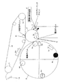
以下、本発明の実施の形態を図面を参照しつつ説明する。図1は本発明に係る画像形成装置の実施の形態を示す図であり、図中、1は画像形成装置、2は本体ケース、3は感光体、4は帯電装置、5は露光装置、6は現像カートリッジ、7は感光体クリーナ、8は現像ロータリーユニット、9はロータリーフレーム、12は中間転写ベルト、13は1次転写ローラ、15は2次転写ローラ、16は電源装置、17は給紙トレイ、20は定着ユニット、21は排紙トレイ、22は紙搬送ユニットを示す。
【0015】
本実施形態の画像形成装置1は、図1に示すように本体ケース2の上部に形成された排紙トレイ21と、前面に開閉自在に挿着された前面カバー2aを有する。本体ケース2内には、複数の現像カートリッジを搭載した現像ロータリーユニット8、静電潜像が形成され現像されてトナー像が形成される感光体3、感光体3上のトナー像が転写される中間転写ユニット、各駆動モータやバイアスを制御する制御ユニット、電源装置16、記録媒体を収容する給紙トレイ17、記録媒体上のトナー像を定着する定着ユニット20などが配設されている。また、前面カバー2a内には給紙トレイ17から記録媒体を2次転写ローラ15を通して定着ユニット20に搬送する紙搬送ユニット22が配設されている。そして、各ユニットは、本体に対して着脱可能な構成であり、メンテナンス時等には一体的に取り外して修理または交換を行うことが可能な構成になっている。
【0016】
像担持体である感光体3は、薄肉円筒状の導電性基材と、その表面に形成された感光層とを有する。その感光体3の外周には、回転方向に沿って感光体3を一様に帯電するための帯電装置4、感光体3上に静電潜像を形成するための露光装置(又は書込装置)5、静電潜像を現像するための現像ロータリーユニット8、感光体3上のトナー像が転写される中間転写ベルト12、及び中間転写ベルト12にトナー像を1次転写する中間転写ユニット、1次転写後の感光体3の表面をクリーニングする感光体クリーナ7などが配設されている。
【0017】
中間転写ユニットは、駆動ローラ10および従動ローラ11と、無端状のベルトからなり両ローラ10、11に巻架され図示矢印方向に駆動されて感光体3上のトナー像が転写される中間転写ベルト12と、中間転写ベルト12の裏面で感光体3に対向して配設され感光体3上のトナー像を中間転写ベルト12に1次転写するための一次転写ローラ13と、中間転写ベルト12上の残留トナーを除去する転写ベルトクリーナ14と、駆動ローラ10に対向して配設され、中間転写ベルト12上に形成された4色フルカラーのトナー像を記録媒体(紙等)上に2次転写するための二次転写ローラ15とからなっている。
【0018】
露光装置5の下方には電源機器16が配設され、また本体ケース2の底部には給紙カセット17が配設され、給紙カセット17内の記録媒体は、ピックアップローラ18、シート材搬送路19、二次転写ローラ15、定着装置20を経て排紙トレイ21に搬送されるように構成されている。なお、給紙カセット17は把手17bにより装置前方に引き出し可能に装着されているとともに、用紙サイズが大きい場合に対応できるように、装置後方に突出するように引き出し可能に補助カセット17aが装着されている。
【0019】
上記構成の画像形成装置1では、露光装置5に画像形成信号が入力されると、制御ユニットによる駆動モータやバイアスの制御にしたがい、感光体3、現像ロータリーユニット8の現像ローラ6a、中間転写ベルト12が回転駆動され、まず、感光体3の外周面が帯電装置4によって一様に帯電される。しかる後、露光装置5によって感光体3の表面に画像情報に応じた選択的な露光がなされ、静電潜像が形成される。このとき、現像ロータリーユニット8は、現像カートリッジ6の現像ローラ6aが感光体3に当接するように回転移動する。このことにより、静電潜像のトナー像が感光体3上に形成される。感光体3上に形成されたトナー像は、トナーの帯電極性と逆極性の1次転写電圧が印加された1次転写ローラ13により中間転写ベルト12上に転写され、感光体3上に残留しているトナーは感光体クリーナ7によって除去される。
【0020】
フルカラー画像形成装置では、現像ロータリーユニット8にイエローY、マゼンタM、シアンC、ブラックKのそれぞれの現像カートリッジ6Y、6M、6C、6Kが着脱可能に搭載される。そして、画像形成動作では、露光装置5によって感光体3の表面に第1色、例えばイエローYの画像情報に応じた選択的な露光がなされ、イエローYの静電潜像が形成される。このとき、現像ロータリーユニット8は、イエローYの現像カートリッジ6Yの現像ローラ6aが感光体3に当接するように回転移動し、イエローYの静電潜像のトナー像が感光体3上に形成され、続けてそのトナー像がトナーの帯電極性と逆極性の1次転写電圧が印加された1次転写ローラ13により中間転写ベルト12上に転写される。
【0021】
この間、転写ベルトクリーナ14、2次転写ローラ15は、中間転写ベルト12から離間されている。4色フルカラー画像は、この一連の処理が画像形成信号の第2色目、第3色目、第4色目に対応して繰り返して実行されることにより、各画像形成信号の内容に応じたイエローY、マゼンタM、シアンC、ブラックKのトナー像が感光体3から順次中間転写ベルト12上において重ね合わされて転写され形成される。
【0022】
そして、各色トナー像の重畳された画像が2次転写ローラ15に達するタイミングで、給紙トレイ17の記録媒体がピックアップローラ18から、レジローラ、シート材搬送路19を通して2次転写ローラ15に搬送され、2次転写ローラ15が中間転写ベルト12に押圧されるとともに2次転写電圧が印加されて、中間転写ベルト12上のトナー像が2次転写ローラ15で記録媒体上に転写される。このようにしてトナー像が転写された記録媒体は紙搬送ユニット22により定着ユニット20まで搬送されると、定着ユニット20により記録媒体上のトナー像が加熱加圧されて定着される。中間転写ベルト12上に残留しているトナーは転写ベルトクリーナ14によって除去される。
【0023】
なお、両面プリントの場合には、定着ユニット20を出た記録媒体は、その後端が先端となるようにスイッチバックされ、紙搬送ユニット22の両面印刷用搬送路を経て、再び二次転写ローラ15に供給され、中間転写ベルト12上のフルカラートナー像が記録媒体上に転写され、再び定着ユニット20により加熱加圧され定着され、排紙トレイ21に排紙される。
【0024】
本実施形態の現像ロータリーユニット8では、上記のように4つの現像カートリッジ6Y、6M、6C、6Kが着脱可能に搭載され、4色のフルカラーの画像形成装置となっているが、モノクロの画像形成装置として、トナーがブラックKの現像カートリッジ6Kのみを装着し搭載して、現像カートリッジ6Kが待機位置(ホームポジション)で待機し、画像形成時にブラックKの現像カートリッジ6Kが待機位置から回転移動して現像位置で、感光体3上の静電潜像をトナー像に現像してもよい。このことにより、フルカラーとモノカラーに同じ設計仕様の現像ロータリーユニット8を用いることができ、フルカラーとモノカラーの共用によりフルカラー専用、モノカラー専用の画像形成装置を設計するのに比べて保守管理、設計、製造のコストを大幅に削減することができる。
【0025】
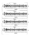
次に感光体の速度ムラに関するメカニズムとその対処について説明する。図2は感光体の速度ムラが観察される測定データを示す図、図3は動作シーケンスにより感光体の速度ムラ発生領域を説明するための図である。
【0026】
本実施形態のカラー画像形成装置において、現像ロータリーユニット8がホームポジションにある待機状態では、現像カートリッジ6Y、6M、6C、6Kのいずれも感光体3と対向する現像位置にない。つまり、現像ローラ6aが感光体3に当接していない。通常、現像ローラ6aが感光体3に当接していると、露光装置5からの画像書き込みがなくても、若干のかぶりトナーが感光体3上に載り、そのかぶりトナーが感光体クリーナ7との当接面で一種の潤滑剤として作用することにより、感光体クリーナ7に対して感光体3が円滑に摩擦摺動するので、感光体3の速度ムラは僅かである。
【0027】
しかし、現像ローラ6aが感光体3から離間している間に、感光体クリーナ7によりクリーニングされた感光体3面が回転移動して再び感光体クリーナ7と当接して摩擦摺動すると、上記かぶりトナーが全くなくない状態であるため、いわゆる潤滑剤がなく感光体クリーナ7との当接面で感光体3の摩擦抵抗が大きくなって、感光体3の回転速度が不安定になる。つまり、感光体3の表面の摩擦抵抗が大きくなることにより、感光体クリーナ7に対して感光体3が微小のロック、滑り現象を繰り返し、感光体3の速度ムラ、震動が現れると考えられる。
【0028】
このことは、図2によって認識できる。図2において、縦軸に速度ムラ、横軸に時間を表しているが、まず、ここで周期的に大きな速度ムラが現れているのは、回転検出を行うエンコーダのつなぎ目に当たり信号の乱れであり、直接回転の乱れを示しているのではないので無視される。この測定データは、各色Y、M、C、Kにおいて、画像信号により露光を行うタイミングに合わせて現像カートリッジ6を切り換えて感光体3に現像ローラ6aを当接させる現像色切り換え動作を行っているものであり、その露光開始直後に速度ムラの大きい時間帯t(0〜6の間)が観察されている。そして、この速度ムラは、現像ローラ6aが感光体3に当接してからその当接面が感光体クリーナ7に到達するまでの時間続いてから、その後解消している。
【0029】
さらに、動作シーケンスにより感光体の速度ムラ発生領域について説明する。本実施形態に係るカラー画像形成装置の動作シーケンスの概要を示したのが図3であり、vsync信号、転写ベルトモータ、スキャナモータ、画像信号、ロータリ動作、現像動作、1次転写バイアス、感光体クリーナ位置、2次転写バイアス、転写ベルトクリーナの位置を示し、斜め点線mは現像動作開始ポイント、つまり現像色切り換え動作が終了して現像ローラ6aが当接した感光体3上の位置が感光体クリーナ位置に回転移動する対応位置を示し、同じく斜め点線nは現像動作終了ポイント、つまり現像色切り換え動作の開始により現像ローラ6aが離れた感光体3上の位置について示している。
【0030】
図3に示すように感光体3、現像ロータリーユニット8の現像ローラ6a、中媒駆動モータや露光装置5のスキャナモータの駆動を開始して中間転写ベルト12、スキャナ、感光体3の回転駆動を開始してから、現像ロータリーユニット8による現像色切り換え動作を開始し、感光体3の外周面が帯電装置4によって一様に帯電され、vsync信号に基づき同期をとって画像信号をオンにして露光を行い、順次画像形成が行われる。そして、画像形成の開始に同期して1次転写バイアスをオンにすることにより、感光体上のトナー像が中間転写ベルト12上に1次転写される。
【0031】
図1に示すように感光体3上で露光ポイントは、現像位置より回転上流側にあり、図3に示すように露光を開始して画像信号オンすると、その露光位置が現像位置に回転移動するまでに現像ローラ6aが感光体3に当接すればよいので、現像ローラ6aが感光体3に当接して現像開始する時点は、画像信号オンの時点より若干遅れる。この現像ローラ6aが当接した感光体3上の位置が感光体クリーナ位置に回転移動するのは図示点線mが感光体クリーナ位置に交差する時点になる。
【0032】
したがって、画像信号オンの時点から図示点線mが感光体クリーナ位置に交差する時点までの時間t′は、現像ローラ6aが当接していなかった、つまり潤滑剤となるトナーが感光体3上に存在しない状態で感光体3の周面が感光体クリーナ7と摩擦摺動することになるので、このことにより感光体3の速度ムラの発生領域となる。第2色〜第4色においても現像動作終了ポイント(n)から現像動作の開始ポイント(m)に対応して同様の感光体3の速度ムラの発生領域が同様に現れる。
【0033】
本実施形態のカラー画像形成装置は、現像ロータリーユニット8が現像色切り換え動作を行って露光装置5の露光ビームBによる潜像形成を開始する時及びそれ以降にわたり感光体クリーナ7のブレードに対向する感光体3上にトナーが存在するようにトナーを補給するものである。したがって、現像器の切り換え動作中に、本来現像ローラ6aに当接する感光体3の現像位置対向面に対して、潜像形成開始時に感光体クリーナ7のブレードに対向する位置まで移動する感光体3上にトナーの補給を行う。トナーの補給は、感光体3上のトナー像を中間転写ベルト12に1次転写する1次転写ポイントにおいて、中間転写ベルト12上から対策画像のトナー像を感光体3上に逆転写することにより行う。或いは、感光体3の周囲に潤滑剤塗布手段を配設することにより行うこともできる。
【0034】
このように画像信号オンとなり露光が開始する前は、直接画像に影響がなく速度ムラによる画像ムラも生じないので、少なくとも画像信号オンの時点、つまり感光体3上に潜像形成を開始する露光開始時に感光体クリーナ7のブレードに対向する感光体3上にトナーが補給されていればよい。このことから逆に、感光体クリーナ7のブレードに対向する感光体3上にトナーその他の潤滑剤が補給されていないときには露光を行わないようにすることも、画像ムラを発生させないようにする点で有効である。
【0035】
図4は対策画像を形成する実施の形態の動作シーケンスを示す図、図5は感光体の周囲に配設される潤滑剤塗布手段として潤滑剤塗布装置を用いた実施の形態を示す図、図6は感光体の周囲に配設される潤滑剤塗布手段として回転ブラシを用いた実施の形態を示す図である。
【0036】
中間転写ベルト12から感光体3上にトナー像を逆転写するためには、中間転写ベルト12上にあるトナーを除去しないで1次転写ポイントまで搬送するように転写ベルトクリーナ14を離間させることであり、その中間転写ベルト12上のトナー像は、感光体3上からトナー像やかぶりトナーが1次転写ポイントで転写されたものである。
【0037】
中間転写ベルト12上に対策画像のトナー像を形成して保持し感光体3上に逆転写する実施形態の動作シーケンスを示したのが図4である。この場合には、図4に示すように印刷画像の形成に先立ってまず、対策画像を形成して1次転写バイアスを制御して予め中間転写ベルト12上に対策画像のトナー像を転写してから(▲1▼)、第1色目の画像形成に入る。このことにより、感光体3上には対策画像のトナー像の残留トナーが存在するため、感光体3と感光体クリーナ7とは円滑に摩擦摺動し速度ムラは生じない。そして、第2色目〜第4色目では、現像ローラ6aが感光体3に当接しない現像色切り換え動作中の感光体3上に1次転写バイアスを制御して中間転写ベルト12上から対策画像のトナー像を逆転写してトナーを補給する(▲2▼〜▲4▼)。このことにより、少なくとも露光ビームBによる潜像形成中に感光体3と感光体クリーナ7との当接部で潤滑剤が存在しない時間をなくすことができる。
【0038】
現像ローラ6aが現像位置で感光体3に当接している状態を考えると、感光体3上にトナー像が形成されないとき、現像ローラ6aから感光体3へのかぶりトナーによる感光体クリーナ7との当接部での潤滑剤の役目は十分である。また、感光体3上にトナー像が形成されたとき、そのトナー像が1次転写ポイントで中間転写ベルト12に1次転写された後の残留トナーによる感光体クリーナ7との当接部での潤滑剤としての役目は十分である。
【0039】
このように感光体3上に潤滑剤として逆転写する中間転写ベルト12からのトナー量は僅かでよいので、1次転写ポイントで逆転写するトナー量を制御することにより、中間転写ベルト12から複数回繰り返してトナーの一部を少しずつ逆転写させるようにすることもできる。この繰り返し回数は、例えば画像形成回数により、また、対策画像のトナー量、逆転写の際のバイアスにより制御することができる。
【0040】
感光体3上から予め中間転写ベルト12に転写するトナー像(対策画像)は、例えば露光装置5からの露光ビームBによる露光を1ラインオン、10ラインオフとするような周期的な線画像や、規則的なドットパターンによる画像を使うことができる。中間転写ベルト12上においては、画像領域と非画像領域が割り当てられており、そのポイントから露光装置5が画像信号にしたがって露光ビームBによる露光を開始するとき、感光体3と感光体クリーナ7が当接するポイントが求まり、その計算に基づき予めトナーを転写する領域が決定される。
【0041】
上記実施形態では、予め中間転写ベルト12上に対策画像のトナー像を載せて現像ロータリーユニット8の現像色切り換え動作時に現像ローラ6aが離間して感光体3上の潤滑剤がなくなる領域で中間転写ベルト12上から逆転写によりトナーを感光体3上に補給するように対策画像の形成、1次転写、転写ベルトクリーナ14の制御を行ったが、このような画像形成を行わずに、直接感光体3上に潤滑剤を供給するように、例えば図5に示すように潤滑剤塗布装置31を設け、クリーニングにより感光体3から取り除かれた排トナーとは別に潤滑用トナーを含むステアリン酸亜鉛などの潤滑剤を潤滑剤塗布装置31により感光体3の周面に塗布して、常に感光体3の周面から潤滑剤を切らさないようにしてもよい。また、図6に示すように感光体クリーナ7の近傍に回転ブラシ32や刷毛、ローラ等の排トナー循環機構を設け、感光体クリーナ7で感光体3から取り除かれた排トナーをこれら回転ブラシ32や刷毛、ローラ等の排トナー循環機構で感光体3の周面に循環させて戻すようにしてもよい。
【0042】
図7は感光体クリーナのブレードの接線に対する支点の位置関係の実施の形態を示す図であり、感光体クリーナ7は、図7(A)に示すようにブレード7aが支点7bを中心にしてバネ7cにより所定の圧力で感光体3に押圧されているが、その支点7bの位置は、感光体3にブレード7aが当接している接線pの上、あるいは図7(B)に示すようにその接線pより外側(感光体3と反対側)に設けられる。このような支点7bの位置とすることにより、感光体クリーナ7の支点7bを感光体3に当接する接線pより内側(感光体3側)に設けるよりも、感光体3の回転の乱れに対しても感光体3に対する感光体クリーナ7の当接状態を安定に保つことができる。
【0043】
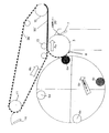
次に、感光体3上に中間転写ベルト12からトナーを補給する制御について具体的に説明する。図8は対策画像を感光体上に形成している様子を説明するための図、図9は対策画像を感光体上から中間転写ベルトに転写し、引き続き印字画像を感光体上に形成している様子を説明するための図、図10は印字画像の形成が終了し中間転写ベルトに転写している様子を説明するための図、図11は現像ロータリーユニットが現像色切り換え動作を開始すると同時に中間転写ベルト上から感光体上にトナーを逆転写している様子を説明するための図、図12は次のトナー色の画像形成を開始している様子を説明するための図、図13は最終色の画像形成中の様子を説明するための図、図14は全色色重ねした画像を2次転写している様子を説明するための図、図15は転写ベルトクリーナのクリーニング開始タイミング時の様子を説明するための図である。
【0044】
本実施形態の画像形成装置1では、画像形成動作に先立ってまず、感光体3、現像ロータリーユニット8の現像ローラ6a、中間転写ベルト12がそれぞれRo、Rd、Rbの方向に回転駆動され、感光体3の外周面が帯電装置4によって一様に帯電される。しかる後、図8に示すように露光装置5によって感光体3の表面に対策画像の露光がなされ、静電潜像が形成される。このとき、現像ロータリーユニット8は、現像カートリッジ6の現像ローラ6aが感光体3に当接するように回転移動する。このことにより、対策画像のトナー像35が感光体3上に形成される。
【0045】
感光体3上に対策画像のトナー像35が形成されると、図9に示すようにトナーの帯電極性と逆極性の1次転写電圧が印加された1次転写ローラ13により感光体3上から中間転写ベルト12上にトナー像35′として転写される。そして、引き続き印字画像の露光、現像が開始されてトナー像36が形成され、1次転写が開始される。
【0046】
先に説明したように転写ベルトクリーナ14、2次転写ローラ15は、中間転写ベルト12から離間されているので、感光体3上での第1色の印刷画像の形成が終了すると、図10に示すように中間転写ベルト12上の対策画像のトナー像35′は、1次転写ポイント近くまで移動する。そして、第2色の画像形成を行うために現像ロータリーユニット8が現像色切り換え動作を開始し、図11に示すように現像ロータリーユニット8がRrの方向に回転移動して現像ローラ6aが感光体3から離間すると、先に中間転写ベルト12上に転写されている対策画像のトナー像35′が1次転写ポイントに到達して感光体3上にトナー像35″として逆転写される。この逆転写により、現像ローラ6aが感光体3から離間しても1次転写ポイントで感光体3上にトナーが補給され、感光体クリーナ7との当接部に潤滑剤として供給される。
【0047】
同様に、第2色の画像形成が開始されると、図12に示すように露光装置5から露光ビームBにより感光体3上に露光が行われる時点において、感光体クリーナ7との当接部には、潤滑剤として中間転写ベルト12から逆転写されて感光体3上に補給されたトナー35″が供給されるので、感光体3の安定した回転が維持できる。以下同様に第3色の画像形成動作も実行される。
【0048】
そして、第4色目の画像形成が開始されると、図13に示すように中間転写ベルト12上に全色の画像が色重ねされると共に、図14に示すように2次転写ローラ15が中間転写ベルト12に当接してフルカラーのトナー像37′が中間転写ベルト12から記録媒体に2次転写が開始され転写画像37″が形成される。この間、転写ベルトクリーナ14は、図8〜図14に示すように中間転写ベルト12から離間しているが、図15に示すように中間転写ベルト12上の対策画像のトナー像35′が通過すると、中間転写ベルト12に当接して中間転写ベルトの印刷画像領域に対応する残留トナーのクリーニングを開始し、中間転写ベルト12上の印刷画像を2次転写した後の残留トナーを除去する。
【0049】
なお、本発明は、上記実施の形態に限定されるものではなく、種々の変形が可能である。例えば上記実施の形態では、ロータリー式の4色フルカラー画像形成装置の現像色切り換え動作中の問題を解決するものとして説明したが、待機時には現像ローラを感光体から離間した状態で保持し、画像形成を行うジョブ実行に応じて現像ローラを感光体に当接させるものであれば、現像ロータリーユニットを搭載したロータリー式の画像形成装置でなくても、また、現像ロータリーユニットを搭載しているかいないかにかかわらずモノ黒画像形成装置にも、同様に適用でき同様の課題を解決することができることは言うまでもない。さらに、中間転写ベルトから感光体上に対策画像を逆転写する際には、逆方向のバイアスを印加するだけでなく、1次転写バイアスを低くして電位差を小さくしたりオフにするように1次転写バイアスを制御してもよいし、1次転写の速度を変えたり、1次転写ローラの圧力を変えてもよい。また、対策画像は、第1色目やブラックKのトナー像で形成するだけでなく、例えば視認性の低いイエローYのトナー像で形成してもよいし、第1色の画像形成の直前に限らず、カートリッジやユニット交換時の待機状態への位置設定動作時や、待機時から画像形成動作を開始する時に行い、その後は、ジョブの実行回数に応じて一定の基準で中間転写ベルトに形成しておくようにしてもよい。
【0050】
【発明の効果】
以上の説明から明らかなように、本発明によれば、静電潜像が形成される像担持体と、像担持体に潜像形成を行う潜像形成手段と、像担持体に当接して現像を行う現像ローラを有する現像手段と、像担持体上に現像されたトナー像を中間転写媒体上に転写する第一の転写手段と、中間転写媒体上に転写されたトナー像を記録媒体上に転写する第二の転写手段と、像担持体上に当接して転写後の残留トナーを除去する第一のクリーニング手段と、中間転写媒体上に当接させ又は離間させ、当接させることにより中間転写媒体上のトナーを除去する第二のクリーニング手段とを備え、前記現像手段により現像ローラが前記像担持体から離間して現像切り換え動作を行うようになった画像形成装置において、第二のクリーニング手段のブレードを離間させ中間転写媒体上に転写されたトナーを除去することなく搬送して、第一の転写手段により搬送されてきたトナーを像担持体上に逆転写させ、少なくとも潜像形成手段による潜像形成開始時の第一のクリーニング手段のブレードに対向する像担持体上にトナーが存在するようにトナーを補給するトナー補給手段を備えたので、潜像形成開始時にクリーニング手段のブレードに対向する像担持体上にトナーが供給されていない状態をなくし、像担持体上に当接するクリーニング手段を円滑に摩擦摺動させることができ、像担持体の速度ムラを低減することができる。したがって、クリーニング部材との摩擦摺動による像担持体の速度ムラをなくし、特に現像ロータリーユニットを搭載し現像切り換え動作を行う画像形成装置の静電潜像の形成時における像担持体の速度ムラをなくすことができる。
【図面の簡単な説明】
【図1】 本発明に係る画像形成装置の実施の形態を示す図である。
【図2】 感光体の速度ムラが観察される測定データを示す図である。
【図3】 動作シーケンスにより感光体の速度ムラ発生領域を説明するための図である。
【図4】 対策画像を形成する実施の形態の動作シーケンスを示す図である。
【図5】 感光体の周囲に配設される潤滑剤塗布手段として潤滑剤塗布装置を用いた実施の形態を示す図である。
【図6】 感光体の周囲に配設される潤滑剤塗布手段として回転ブラシを用いた実施の形態を示す図である。
【図7】 感光体クリーナのブレードの接線に対する支点の位置関係の実施の形態を示す図である。
【図8】 対策画像を感光体上に形成している様子を説明するための図である。
【図9】 対策画像を感光体上から中間転写ベルトに転写し、引き続き印字画像を感光体上に形成している様子を説明するための図である。
【図10】 印字画像の形成が終了し中間転写ベルトに転写している様子を説明するための図である。
【図11】 現像ロータリーユニットが現像色切り換え動作を開始すると同時に中間転写ベルト上から感光体上にトナーを逆転写している様子を説明するための図である。
【図12】 次のトナー色の画像形成を開始している様子を説明するための図である。
【図13】 最終色の画像形成中の様子を説明するための図である。
【図14】 全色色重ねした画像を2次転写している様子を説明するための図である。
【図15】 転写ベルトクリーナのクリーニング開始タイミング時の様子を説明するための図である。
【符号の説明】
1…画像形成装置、2…本体ケース、3…感光体、4…帯電装置、5…露光装置、6…現像カートリッジ、7…感光体クリーナ、8…現像ロータリーユニット、9…ロータリーフレーム、12…中間転写ベルト、13…1次転写ローラ、15…2次転写ローラ、16…電源装置、17…給紙トレイ、20…定着ユニット、21…排紙トレイ、22…紙搬送ユニット[0001]
BACKGROUND OF THE INVENTION
The present invention relates to an image bearing member on which an electrostatic latent image is formed, a latent image forming unit that forms a latent image on the image bearing member, and a developing unit that has a developing roller that contacts and develops the image bearing member. Transfer means for transferring the developed toner image on the image carrier onto the transfer body, and cleaning means for contacting the image carrier to remove residual toner after transfer. The image forming apparatus in which the developing roller is separated from the image carrier to perform the development switching operation.
[0002]
[Prior art]
In the image forming apparatus, a charging device for uniformly charging the photoconductor along the rotation direction on the outer periphery of the photoconductor as an image carrier, an exposure device for forming an electrostatic latent image on the photoconductor, A developing device for developing the electrostatic latent image, a transfer device for transferring the toner image on the photosensitive member to the transfer member, a cleaner for cleaning the surface of the photosensitive member after the transfer, and the like are provided. Then, the electrostatic latent image formed on the photosensitive member by the exposure device is developed by the developing device to form a toner image, the formed toner image is transferred to the transfer member, and the residual image on the photosensitive member after the transfer is transferred. The toner is removed from the photoreceptor by a cleaner.
[0003]
In the case of a rotary-type full-color image forming apparatus that forms a full-color image, a color toner image formed on a photosensitive member by a developing device of yellow Y, magenta M, cyan C, and black K is placed on an intermediate transfer medium. Sequential transfer and color overlay. Therefore, each toner developing cartridge is detachably mounted on the developing rotary unit, and each time an electrostatic latent image for each color is formed on the photoreceptor, the developing rotary unit is driven by a developing color switching operation to The developing cartridge is rotated to the developing position to perform the developing operation (see, for example,
[0004]
[Patent Document 1]
JP 2002-82532 A
[Patent Document 2]
Japanese Patent Laid-Open No. 2003-66801
[Problems to be solved by the invention]
In the image forming apparatus, the electrostatic latent image on the photosensitive member is repeatedly exposed in the rotation axis direction (main scanning direction) of the photosensitive member by the exposure beam of the exposure device whose outer peripheral surface that is uniformly rotated is modulated by the image forming signal. Is formed. Since the exposure beam is scanned and exposed to form a latent image while the photoconductor is rotating, if the photoconductor rotates unstable and there are vibrations or unevenness, streaks appear in the sub-scanning direction, resulting in banding. This causes the problem of deterioration.
[0007]
Factors that cause unstable rotation of the photosensitive member and cause vibration and unevenness are due to the structure of the train wheel of the drive system, but there are members that contact the outer periphery of the photosensitive member, cleaning members, and rotary type. In such a color image forming apparatus, there is a developing rotary unit for performing a developing color switching operation.
[0008]
When the toner image formed on the photosensitive member is transferred to the transfer member, the cleaning member cleans the residual toner on the photosensitive member after the transfer. In order to enhance the cleaning effect, an appropriate member is used. In addition, the residual toner is removed from the photosensitive member by contacting the outer peripheral surface of the photosensitive member with a constant pressure by a spring or the like. If the contact pressure is weak, the cleaning effect is naturally reduced. However, if the contact pressure is increased, irregular vibration associated with frictional sliding between the outer peripheral surface of the photosensitive member and the cleaning member is caused. Further, the angle at which the blade contacts the outer peripheral surface of the photosensitive member, the position of the fulcrum that supports the cleaning member with respect to the tangent to the contact surface, and the like also have an effect.
[0009]
Further, in an image forming apparatus in which the developing roller is retracted away from the developing position of the photosensitive member or the development is switched with respect to the image forming device in which the developing roller is always in contact with the photosensitive member, the speed variation of the photosensitive member is reduced. It is observed that is prone to occur. For example, in a rotary type color image forming apparatus provided with a developing rotary unit, the developing rotary unit is rotated and moved by a developing color switching operation, and the mounted developing cartridge is repeatedly contacted and separated from the photosensitive member each time. There is a problem that the state of the outer peripheral surface of the photoconductor is not uniformly maintained in the contact state and the separated state, the frictional sliding of the cleaning member is not smoothly performed, and the speed of the photoconductor becomes unstable. is there.
[0010]
[Means for Solving the Problems]
The present invention solves the above-described problems, eliminates unevenness of the speed of the image carrier due to frictional sliding with the cleaning member, and in particular, provides an electrostatic latent image of an image forming apparatus that is equipped with a developing rotary unit and performs a developing switching operation. It is intended to eliminate unevenness in the speed of the image carrier during image formation.
[0011]
Therefore, the present invention includes an image carrier on which an electrostatic latent image is formed, a latent image forming unit that forms a latent image on the image carrier, and a developing roller that performs development in contact with the image carrier. A developing means; a first transfer means for transferring the toner image developed on the image carrier onto an intermediate transfer medium; and a second for transferring the toner image transferred onto the intermediate transfer medium onto a recording medium. Transfer means, a first cleaning means that contacts the image carrier to remove residual toner after transfer, and the intermediate transfer medium by contacting or separating and contacting the intermediate transfer medium. A second cleaning unit for removing toner on the medium , wherein the developing unit separates the developing roller from the image carrier and performs a development switching operation. Means breaker And the toner transferred on the intermediate transfer medium is transported without being removed, and the toner transported by the first transfer means is reversely transferred onto the image carrier, and at least the latent image is transferred. And a toner replenishing unit that replenishes the toner so that the toner is present on the image bearing member facing the blade of the first cleaning unit at the start of latent image formation by the forming unit.
[0014]
DETAILED DESCRIPTION OF THE INVENTION
Hereinafter, embodiments of the present invention will be described with reference to the drawings. FIG. 1 is a diagram showing an embodiment of an image forming apparatus according to the present invention. In the figure, 1 is an image forming apparatus, 2 is a main body case, 3 is a photoreceptor, 4 is a charging device, 5 is an exposure device, Is a developing cartridge, 7 is a photoconductor cleaner, 8 is a developing rotary unit, 9 is a rotary frame, 12 is an intermediate transfer belt, 13 is a primary transfer roller, 15 is a secondary transfer roller, 16 is a power supply device, and 17 is paper feed. A tray, 20 is a fixing unit, 21 is a paper discharge tray, and 22 is a paper transport unit.
[0015]
As shown in FIG. 1, the
[0016]
The
[0017]
The intermediate transfer unit is made up of a driving
[0018]
A
[0019]
In the
[0020]
In the full-color image forming apparatus, development cartridges 6Y, 6M, 6C, and 6K for yellow Y, magenta M, cyan C, and black K are detachably mounted on the
[0021]
During this time, the
[0022]
The recording medium on the
[0023]
In the case of double-sided printing, the recording medium that has exited the fixing
[0024]
In the developing
[0025]
Next, a mechanism related to the speed unevenness of the photoreceptor and countermeasures will be described. FIG. 2 is a diagram illustrating measurement data in which unevenness in speed of the photosensitive member is observed, and FIG. 3 is a diagram for explaining a region where unevenness in speed of the photosensitive member is generated according to an operation sequence.
[0026]
In the color image forming apparatus of the present embodiment, none of the developing cartridges 6Y, 6M, 6C, and 6K is in the developing position facing the
[0027]
However, when the developing
[0028]
This can be recognized by FIG. In FIG. 2, the vertical axis represents speed unevenness and the horizontal axis represents time. First, the large speed unevenness appears periodically at the joint of the encoder that performs rotation detection. It is ignored because it does not directly indicate rotational disturbance. This measurement data is used for each color Y, M, C, and K to perform a development color switching operation in which the
[0029]
Further, the speed unevenness occurrence region of the photoconductor will be described based on the operation sequence. FIG. 3 shows an outline of the operation sequence of the color image forming apparatus according to the present embodiment. The vsync signal, the transfer belt motor, the scanner motor, the image signal, the rotary operation, the developing operation, the primary transfer bias, and the photoconductor. The position of the cleaner, the secondary transfer bias, and the position of the transfer belt cleaner are shown. The oblique dotted line m is the developing operation start point, that is, the position on the
[0030]
As shown in FIG. 3, the
[0031]
As shown in FIG. 1, the exposure point on the
[0032]
Therefore, the developing
[0033]
The color image forming apparatus of this embodiment is opposed to the blades of the
[0034]
Thus, before the image signal is turned on and exposure is started, there is no direct influence on the image and image unevenness due to speed unevenness does not occur. Therefore, at least when the image signal is turned on, that is, exposure for starting latent image formation on the
[0035]
FIG. 4 is a diagram showing an operation sequence of an embodiment for forming a countermeasure image. FIG. 5 is a diagram showing an embodiment in which a lubricant application device is used as a lubricant application means disposed around the photosensitive member. 6 is a view showing an embodiment in which a rotating brush is used as a lubricant application means disposed around the photosensitive member.
[0036]
In order to reversely transfer the toner image from the
[0037]
FIG. 4 shows an operation sequence of an embodiment in which a toner image of a countermeasure image is formed and held on the
[0038]
Considering the state in which the developing
[0039]
As described above, since the amount of toner from the
[0040]
The toner image (countermeasure image) previously transferred from the
[0041]
In the above-described embodiment, the toner image of the countermeasure image is placed on the
[0042]
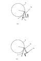
FIG. 7 is a view showing an embodiment of the positional relationship of the fulcrum with respect to the tangent of the blade of the photoconductor cleaner. As shown in FIG. 7A, the
[0043]
Next, control for replenishing toner from the
[0044]
In the
[0045]
When the
[0046]
As described above, since the
[0047]
Similarly, when the image formation of the second color is started, the contact portion with the
[0048]
When image formation of the fourth color is started, the images of all colors are overlaid on the
[0049]
In addition, this invention is not limited to the said embodiment, A various deformation | transformation is possible. For example, in the above embodiment, it has been described as solving the problem during the development color switching operation of the rotary type four-color full-color image forming apparatus. However, during standby, the developing roller is held away from the photoconductor to form an image. As long as the developing roller is brought into contact with the photosensitive member in accordance with the execution of the job, whether the developing rotary unit is installed or not, whether the developing rotary unit is installed or not. Needless to say, the present invention can be applied to the mono black image forming apparatus in the same manner and can solve the same problems. Further, when the countermeasure image is reversely transferred from the intermediate transfer belt onto the photoconductor, not only a reverse bias is applied, but also the primary transfer bias is lowered to reduce the potential difference or to turn it off. The secondary transfer bias may be controlled, the primary transfer speed may be changed, or the pressure of the primary transfer roller may be changed. The countermeasure image is not only formed with the first color or black K toner image, but may be formed with, for example, a low-visibility yellow Y toner image, or only immediately before the first color image formation. First, it is performed when setting the position to the standby state when replacing the cartridge or unit, or when starting the image forming operation from the standby state, and after that, it is formed on the intermediate transfer belt on a constant basis according to the number of job executions. You may make it leave.
[0050]
【The invention's effect】
As is apparent from the above description, according to the present invention, an image carrier on which an electrostatic latent image is formed, a latent image forming unit for forming a latent image on the image carrier, and a contact with the image carrier. A developing means having a developing roller for developing; a first transfer means for transferring a toner image developed on the image carrier onto the intermediate transfer medium; and a toner image transferred on the intermediate transfer medium on the recording medium. A second transfer means for transferring the toner onto the image carrier, a first cleaning means for contacting the image carrier to remove residual toner after transfer, and abutting or separating on the intermediate transfer medium. And a second cleaning unit that removes toner on the intermediate transfer medium, and a developing roller is separated from the image carrier by the developing unit to perform a development switching operation . Remove the cleaning blade. The toner transferred onto the intermediate transfer medium is transported without being removed, and the toner transported by the first transfer means is reversely transferred onto the image carrier, and at least the latent image forming means is started by the latent image forming means. The toner carrying means for replenishing the toner so that the toner is present on the image carrying body facing the blade of the first cleaning means at the time, the image carrying body facing the blade of the cleaning means at the start of latent image formation It is possible to eliminate the state where the toner is not supplied on the upper surface, and to smoothly slide the cleaning means in contact with the image carrier, thereby reducing the speed unevenness of the image carrier. Therefore, the speed unevenness of the image carrier due to frictional sliding with the cleaning member is eliminated, and in particular, the speed unevenness of the image carrier during the formation of the electrostatic latent image of the image forming apparatus equipped with the developing rotary unit and performing the development switching operation. Can be eliminated.
[Brief description of the drawings]
FIG. 1 is a diagram showing an embodiment of an image forming apparatus according to the present invention.
FIG. 2 is a diagram showing measurement data in which speed irregularities of a photoreceptor are observed.
FIG. 3 is a diagram for explaining a speed unevenness generation region of a photoconductor by an operation sequence.
FIG. 4 is a diagram illustrating an operation sequence of an embodiment for forming a countermeasure image.
FIG. 5 is a diagram showing an embodiment in which a lubricant applying device is used as a lubricant applying means disposed around a photoreceptor.
FIG. 6 is a diagram showing an embodiment in which a rotating brush is used as a lubricant application unit disposed around a photoconductor.
FIG. 7 is a diagram showing an embodiment of a positional relationship of a fulcrum with respect to a tangent of a blade of a photoconductor cleaner.
FIG. 8 is a diagram for explaining how a countermeasure image is formed on a photoconductor.
FIG. 9 is a diagram for explaining a state in which a countermeasure image is transferred from the photosensitive member to an intermediate transfer belt, and a print image is continuously formed on the photosensitive member.
FIG. 10 is a diagram for explaining a state in which the formation of a print image is completed and transferred to an intermediate transfer belt.
FIG. 11 is a diagram for explaining a state where toner is reversely transferred from the intermediate transfer belt to the photosensitive member at the same time when the developing rotary unit starts the developing color switching operation;
FIG. 12 is a diagram for explaining a state in which image formation of the next toner color is started.
FIG. 13 is a diagram for illustrating a state during image formation of a final color.
FIG. 14 is a diagram for explaining a state in which an image in which all colors are superimposed is secondarily transferred.
FIG. 15 is a view for explaining a state at the timing of starting the cleaning of the transfer belt cleaner.
[Explanation of symbols]
DESCRIPTION OF
Claims (1)
Priority Applications (2)
| Application Number | Priority Date | Filing Date | Title |
|---|---|---|---|
| JP2003147797A JP3835552B2 (en) | 2003-05-26 | 2003-05-26 | Image forming apparatus |
| US10/854,024 US7092660B2 (en) | 2003-05-26 | 2004-05-26 | Image forming apparatus |
Applications Claiming Priority (1)
| Application Number | Priority Date | Filing Date | Title |
|---|---|---|---|
| JP2003147797A JP3835552B2 (en) | 2003-05-26 | 2003-05-26 | Image forming apparatus |
Publications (2)
| Publication Number | Publication Date |
|---|---|
| JP2004348065A JP2004348065A (en) | 2004-12-09 |
| JP3835552B2 true JP3835552B2 (en) | 2006-10-18 |
Family
ID=33534230
Family Applications (1)
| Application Number | Title | Priority Date | Filing Date |
|---|---|---|---|
| JP2003147797A Expired - Fee Related JP3835552B2 (en) | 2003-05-26 | 2003-05-26 | Image forming apparatus |
Country Status (1)
| Country | Link |
|---|---|
| JP (1) | JP3835552B2 (en) |
-
2003
- 2003-05-26 JP JP2003147797A patent/JP3835552B2/en not_active Expired - Fee Related
Also Published As
| Publication number | Publication date |
|---|---|
| JP2004348065A (en) | 2004-12-09 |
Similar Documents
| Publication | Publication Date | Title |
|---|---|---|
| JP3772032B2 (en) | Image forming apparatus | |
| JP3748074B2 (en) | Image forming apparatus | |
| JP3832588B2 (en) | Image forming apparatus | |
| JP3832589B2 (en) | Image forming apparatus | |
| JP3835552B2 (en) | Image forming apparatus | |
| JP3844078B2 (en) | Image forming apparatus | |
| JP4371203B2 (en) | Image forming apparatus | |
| JP2007248559A (en) | Image forming apparatus | |
| JP4371204B2 (en) | Image forming apparatus | |
| JP4386914B2 (en) | Image forming apparatus | |
| JP2007108589A (en) | Image forming apparatus | |
| JP2005070584A (en) | Image forming apparatus | |
| JP2007248547A (en) | Image forming apparatus | |
| JP3877258B2 (en) | Image forming apparatus | |
| JP2010176154A (en) | Image forming apparatus | |
| JP2005070585A (en) | Image forming apparatus | |
| JP4442188B2 (en) | Image forming apparatus | |
| JP4386168B2 (en) | Image forming apparatus | |
| JP4386167B2 (en) | Image forming apparatus | |
| JP4633176B2 (en) | Image forming apparatus | |
| JP2005266448A (en) | Image forming apparatus | |
| JP4356401B2 (en) | Image forming apparatus | |
| JP2006091314A (en) | Image forming apparatus | |
| JP2005292296A (en) | Image forming apparatus | |
| JP2005128230A (en) | Image forming apparatus |
Legal Events
| Date | Code | Title | Description |
|---|---|---|---|
| A621 | Written request for application examination |
Free format text: JAPANESE INTERMEDIATE CODE: A621 Effective date: 20030526 |
|
| A977 | Report on retrieval |
Free format text: JAPANESE INTERMEDIATE CODE: A971007 Effective date: 20050715 |
|
| A131 | Notification of reasons for refusal |
Free format text: JAPANESE INTERMEDIATE CODE: A131 Effective date: 20050720 |
|
| A521 | Written amendment |
Free format text: JAPANESE INTERMEDIATE CODE: A523 Effective date: 20050912 |
|
| A521 | Written amendment |
Free format text: JAPANESE INTERMEDIATE CODE: A523 Effective date: 20050912 |
|
| A131 | Notification of reasons for refusal |
Free format text: JAPANESE INTERMEDIATE CODE: A131 Effective date: 20051026 |
|
| A521 | Written amendment |
Free format text: JAPANESE INTERMEDIATE CODE: A523 Effective date: 20051209 |
|
| A131 | Notification of reasons for refusal |
Free format text: JAPANESE INTERMEDIATE CODE: A131 Effective date: 20060322 |
|
| A521 | Written amendment |
Free format text: JAPANESE INTERMEDIATE CODE: A523 Effective date: 20060403 |
|
| TRDD | Decision of grant or rejection written | ||
| A01 | Written decision to grant a patent or to grant a registration (utility model) |
Free format text: JAPANESE INTERMEDIATE CODE: A01 Effective date: 20060705 |
|
| A61 | First payment of annual fees (during grant procedure) |
Free format text: JAPANESE INTERMEDIATE CODE: A61 Effective date: 20060718 |
|
| R150 | Certificate of patent or registration of utility model |
Free format text: JAPANESE INTERMEDIATE CODE: R150 |
|
| FPAY | Renewal fee payment (event date is renewal date of database) |
Free format text: PAYMENT UNTIL: 20090804 Year of fee payment: 3 |
|
| FPAY | Renewal fee payment (event date is renewal date of database) |
Free format text: PAYMENT UNTIL: 20100804 Year of fee payment: 4 |
|
| FPAY | Renewal fee payment (event date is renewal date of database) |
Free format text: PAYMENT UNTIL: 20110804 Year of fee payment: 5 |
|
| FPAY | Renewal fee payment (event date is renewal date of database) |
Free format text: PAYMENT UNTIL: 20120804 Year of fee payment: 6 |
|
| LAPS | Cancellation because of no payment of annual fees |