JP3832516B2 - Channel selection method and channel selection apparatus - Google Patents
Channel selection method and channel selection apparatus Download PDFInfo
- Publication number
- JP3832516B2 JP3832516B2 JP31862495A JP31862495A JP3832516B2 JP 3832516 B2 JP3832516 B2 JP 3832516B2 JP 31862495 A JP31862495 A JP 31862495A JP 31862495 A JP31862495 A JP 31862495A JP 3832516 B2 JP3832516 B2 JP 3832516B2
- Authority
- JP
- Japan
- Prior art keywords
- channel
- program
- channel selection
- screen
- user
- Prior art date
- Legal status (The legal status is an assumption and is not a legal conclusion. Google has not performed a legal analysis and makes no representation as to the accuracy of the status listed.)
- Expired - Fee Related
Links
Images


Description
【0001】
【発明の属する技術分野】
この発明は、例えば、テレビ受信機やラジオ受信機において、受信可能な多数のプログラム対応チャンネルの中から受信者が高頻度で視聴する番組を容易に選局することができるようにする選局方法および選局装置に関する。
【0002】
ここで、この明細書において、プログラム対応チャンネルというときには、放送局に割り当てられたチャンネル番号を示し、放送波の伝送帯域を分割した周波数帯ごとに番号が付与された伝送チャンネルと区別することとする。ちなみに、例えば現在の日本における地上波によるテレビ放送においては、通常、伝送チャンネルの番号とプログラム対応チャンネルの番号とは一致しているが、北米で放送が開始されたデジタルテレビ放送では、一つの伝送チャンネルに同時に複数の放送局の番組が伝送されたり、異なる伝送チャンネルで、一つの放送局の番組が放送されるような形式となっている。
【0003】
【従来の技術】
テレビ放送やラジオ放送のプログラム対応チャンネルは多数個存在する。例えば前述したデジタルテレビ放送では、150個のプログラム対応チャンネルの放送が可能である。しかしながら、高頻度に視聴するプログラム対応チャンネルは、使用者によって異なるが、特定の複数のプログラム対応チャンネルに限定されることが多い。
【0004】
そこで、例えばテレビ放送の選局に関して、多数個のすべての視聴可能プログラム対応チャンネルの中から選局を行うのではなく、使用者が予め設定した、選局する率の高い好みの複数チャンネルの中から選局を行えるようにした、いわゆるフェイバリット選局機能と呼ばれる選局方法が提案されている。
【0005】
すなわち、この選局方法が採用されているテレビ受信機は、好みのプログラム対応チャンネル(以下、フェイバリットチャンネルという)の設定画面を備えており、使用者は、予め、この設定画面において、自分が高頻度に視聴すると思われるフェイバリットチャンネルを任意に1〜複数個選択しておく。すると、テレビ受信機は内蔵メモリに、設定されたフェイバリットチャンネルを記憶する。
【0006】
そして、リモコンなどにより、この選局方法の機能を選択するキー操作を行うと、当該テレビ受信機は、内蔵メモリから、設定されている1〜複数のフェイバリットチャンネルを読み出し、例えば、その時点における、その読み出したフェイバリットチャンネルの放送内容を、例えば特開昭56−136089号公報に示されているような技術を用いて、画面において複数個の小画面としてチャンネル番号とともに、表示するようにする。
【0007】
そして、使用者は、この画面に表示された複数個の小画面を参照し、その中から、自分が視聴したいプログラム対応チャンネルを選択するようにできる。
【0008】
【発明が解決しようとする課題】
しかしながら、上記のフェイバリット選局機能による選局方法は、使用者が前記フェイバリットチャンネルの設定画面を例えばメニューから選択して呼び出し、1〜複数のフェイバリットチャンネルを設定した後でないと有効に活用することができない。すなわち、この選局方法による選局機能の存在を認識しており、フェイバリットチャンネルの設定をしている使用者のみしか当該選局機能を活用できず、フェイバリットチャンネルが未設定のテレビ受信機の場合には、その選局機能の存在ないしは有効性を使用者に認識させることすらできない場合がある。
【0009】
また、使用者によっては、フェイバリットチャンネルを設定することが煩わしいという者もある。
【0010】
この発明は、以上の点にかんがみ、使用者によるフェイバリットチャンネルの設定、未設定を問わずに、使用者により、選局される可能性の高い1〜複数のプログラム対応チャンネルを識別可能に表示画面に表示して、選局対象とすることができるようにした選局方法および選局装置を提供することを目的とする。
【0011】
【課題を解決するための手段】
前記課題を解決するため、この発明においては、
使用者により予め設定された1〜複数の好みのプログラム対応チャンネルを設定チャンネル第1の記憶部に記憶しておき、所定のキー入力に応じて、前記第1の記憶部から前記好みのプログラム対応チャンネルを読み出し、前記好みのプログラム対応チャンネルを前記使用者が識別可能なように、複数の小画面を用いた表示によって、前記使用者が選局していたプログラム対応チャンネルの番組の主画像と共に表示画面に表示し、この表示画面において、前記使用者が選局操作を行うことにより、前記1〜複数の好みのプログラム対応チャンネルの中から選局を行うようにする選局方法において、
選局チャンネル履歴記憶用の第2の記憶部を設けて、この第2の記憶部に過去の前記プログラム対応チャンネルの選択状態を記憶するようにすると共に、
前記所定のキー入力を受け付けたときに、前記第1の記憶部に前記好みのプログラム対応チャンネルが予め設定されているか否かを判別し、前記好みのプログラム対応チャンネルが未設定であったときには、前記第2の記憶部に記憶されている過去の選局チャンネル履歴に基づくプログラム対応チャンネルを、前記選局チャンネル履歴に基づいた順番で前記複数個の小画面に表示し、この表示画面において、前記使用者の選局操作を受け付けるようにした
ことを特徴とする。
【0012】
また、この発明による選局装置は、
選局制御信号に応じて、放送波から希望するプログラム対応チャンネルの信号を選択する選局手段と、
使用者の選局操作に応じて前記選局制御信号を発生する選局制御信号発生手段と、
使用者により設定された1〜複数のプログラム対応チャンネルを記憶する設定チャンネル記憶手段と、
前記選局手段による過去の前記プログラム対応チャンネルの選択状態を記憶するチャンネル履歴記憶手段と、
所定のキー入力があったときに、前記設定チャンネル記憶手段に、使用者により設定されたプログラム対応チャンネルがあるか否かを判断し、設定されたプログラム対応チャンネルがあるときには、前記設定チャンネル記憶手段に記憶されているプログラム対応チャンネルを前記使用者に識別可能なように、複数の小画面を用いた表示によって、前記使用者が選局していたプログラム対応チャンネルの番組の主画像と共に表示画面に表示し、前記設定されたプログラム対応チャンネルがないときには、前記チャンネル履歴記憶手段に記憶されている過去の選局チャンネル履歴に基づくプログラム対応チャンネルを、前記選局チャンネル履歴に基づいた順番で前記複数個の小画面に表示する制御手段と
を備え、前記使用者の選局操作が前記表示画面の表示からのプログラム対応チャンネルの選択操作を含むことを特徴とする。
【0014】
上記のように構成したこの発明によれば、使用者により、フェイバリットチャンネルが設定されていないときにも、チャンネル履歴記憶手段から読み出された過去に選局されたプログラム対応チャンネルが表示画面に表示される。したがって、使用者により、好みの複数のプログラム対応チャンネルが設定されていないときにも、当該使用者により選局される可能性の高い複数のプログラム対応チャンネルの中から選局を行うようにするフェイバリット選局機能を有効に働かせることができる。
【0015】
【発明の実施の形態】
以下、この発明による選局装置の一実施の形態を、地上波を用いたアナログテレビ放送波の受信用のテレビ受信機の場合を例にとって図を参照しながら説明する。
【0016】
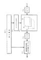
図1は、この実施の形態のテレビ受信機のブロック図である。このテレビ受信機は、表示画面の一部の小領域に子画面を表示することができる、いわゆるピクチャー・イン・ピクチャー(以下、PinPと称する)の機能を有すると共に、1〜複数のフェイバリットチャンネルの中から選局するフェイバリット選局機能を実現するために、表示画面の一部に複数個の小画面を表示できる機能(この機能を、以下マルチ小画面機能という)を有する構成とされている。
【0017】
図1おいて、アンテナ1で受信された放送電波は分配され、第1および第2のチューナ2Mおよび2Sに供給される。これらチューナ2Mおよび2Sでは、後述するマイクロコンピュータによって構成される制御回路100からの選局制御信号によって、所定のプログラム対応チャンネルの選局が行われる。この場合、選局制御信号は、PLLシンセサイザ方式の選局方式であれば、可変分周器の分周比を設定するデータとされる。
【0018】
この場合、選局制御信号は、リモコン信号の送信機(以下リモートコマンダという)などを通じたユーザの選択操作に応じて制御回路100で生成される場合と、後述するフェイバリット選局機能の起動時の場合のように、ユーザの選択操作に関係なく、制御回路100自身において生成される場合とがある。
【0019】
これらチューナ2Mおよび2Sは、選局したプログラム対応チャンネルの放送波信号を、映像中間周波信号に変換して、それぞれ映像中間周波増幅および検波回路3Mおよび3Sに供給する。そして、これら回路3Mおよび3Sにおいて、中間周波信号が増幅されると共に、ビデオ信号およびオーディオ信号が復調される。なお、図1では、説明の簡単のため、復調された後のオーディオ信号系については省略した。
【0020】
映像中間周波および検波回路3Mおよび3Sからの復調されたビデオ信号は、信号切り換え回路4にそれぞれ供給される。この信号切り換え回路4は、制御回路100からの切り換え信号によって切り換えられて、回路3Mおよび3Sの一方からのビデオ信号が主画面用の映像信号処理回路5に供給され、回路3Mおよび3Sの他方からの復調ビデオ信号は子画面用の映像信号処理回路6に供給される。
【0021】
映像信号処理回路5では、制御回路100からの、例えばユーザの画質調整操作に応じた画質調整用信号により、ユーザの好みに応じた画質になるように主画面の画質調整等が行われる。
【0022】
映像信号処理回路6では、PinPの子画面として表示するように、その入力ビデオ信号の画サイズを圧縮する処理等を行なう。
【0023】
子画面用の映像信号処理回路6への入力となるビデオ信号は、また、マルチ小画面処理回路7に供給される。この実施の形態においては、マルチ小画面処理回路7は、図2に示すように構成される。
【0024】
すなわち、マルチ小画面処理回路7は、この回路7に供給されたビデオ信号をデジタル信号に変換するA/Dコンバータ71と、マルチ小画面記憶部72と、この記憶部72へのビデオ信号の書き込み、記憶部72からのビデオ信号の読み出しを制御するメモリコントローラ73と、記憶部72から読み出されたデジタルビデオ信号をアナログビデオ信号に戻すためのD/Aコンバータ74と、チャンネル番号および放送局名重畳回路75とを備える。
【0025】
この実施の形態の場合、マルチ小画面機能においては、異なる5個のプログラム対応チャンネルの放送番組の小画面を、図3の画面表示において小画面P1,P2,P3,P4,P5として示すように、主画面MPに重畳して、ディスプレイ画面10Dに表示できるようにしており、このため、記憶部72は、5個の小画面用メモリ721,722…725を備える。
【0026】
メモリコントローラ73は、メモリ721〜725のうちのいずれのメモリについて書き込みあるいは読み出しを行うかを制御するとともに、その書き込みあるいは読み出しアドレスの制御を行う。
【0027】
チャンネル番号および放送局名重畳回路75は、小画面用メモリ721〜725から読み出され、また、D/Aコンバータ74によりアナログビデオ信号に変換されたそれぞれの小画面データが、いずれのプログラム対応チャンネルの放送番組のものであるかを小画面ごとに識別するためのチャンネル番号とその放送局名を、その小画面データに重畳する。チャンネル番号とその放送局名は、後述のするように、制御回路100から供給される。
【0028】
そして、図3に示すように、小画面P1〜P5内に、各小画面に映出されている番組のプログラム対応チャンネルの番号および放送局名が表示される。
【0029】
制御回路100は、次のようにして、この実施の形態の場合には、5個の小画面P1〜P5を画面10Dに表示するようにする。すなわち、この実施の形態では、フェイバリット選局機能が起動されると、制御回路100は、後述するようにして定められる5個のフェイバリットチャンネルの選局制御信号を、所定の時間間隔、例えば200msec間隔で、チューナ2Mおよび2Sのうちの子画面用とされている方のチューナに、順次にサイクリックに供給する。
【0030】
すると、当該チューナでは、前記200msec毎の間は、その時に与えられる選局制御信号によるフェイバリットチャンネルの選局状態となる。このとき、制御回路100は、チューナに供給する選局制御信号の変更に同期して、マルチ小画面処理回路7のメモリコントローラ73に画像取り込み信号を送る。
【0031】
メモリコントローラ73は、200msec毎の画像取り込み信号を受けて、選局制御信号の変更に同期して、200msec毎に、5個の小画面用メモリ721〜725の一つを順次に切り換え選択する。そして、前記200msecの期間の1つのフェイバリットチャンネルの所定の1フレーム(あるいは1フィールド)分からなる1枚の画像を小画面に対応する小画像の画像データに変換し、その小画像のデータを小画面用メモリ721〜725のうちの選択した一つに書き込む。
【0032】
選局の変更に同期して、5個のメモリ721〜725のうちの書き込みが行われる小画面用メモリが変更されるので、1つのフェイバリットチャンネルの画像は、同じ小画面用メモリに、200msec×5=1秒毎に更新されて書き込まれることになる。この場合、小画面用メモリ721〜725のそれぞれに書き込まれるのは、200msec内の1フレーム分に対応する1毎の小画面(静止画)であり、それが1秒毎に書き替えられるので、小画面P1〜P5の小画像は、いわゆる駒落としの画像となる。
【0033】
そして、メモリコントローラ73は、フェイバリット選局機能が選択されている間、各小画面用メモリ721〜725に書き込んだ小画像を、それぞれ繰り返し読み出す。この場合、小画面用メモリ721〜725からの画像データの読み出しは、主画面のビデオ信号の水平同期信号および垂直同期信号に同期したクロックにより行われ、例えば、メモリ721からの小画像は図3の小画面P1の領域において、メモリ722からの小画像は図3の小画面P2の領域において、……メモリ725からの小画像は図3の小画面P5の領域において、それぞれ読み出されて表示される。この場合、1フレームの間に、前記各領域の区間において5個のメモリ721〜725のすべてから小画像のデータを読み出す。
【0034】
小画面用メモリ721〜725から読み出された画像データは、D/Aコンバータ74でアナログ信号に変換された後、チャンネル番号および放送局名重畳回路75に供給される。この重畳回路75には、制御回路100からメモリ721〜725の読み出しに同期して、対応するプログラム対応チャンネルのチャンネル番号および放送局名を表示する信号が供給されており、各小画面P1〜P5に重畳される。そして、合成回路8を通じてディスプレイ10の画面に、図3に示すようにして5個の小画面P1〜P5内に番号および放送局名が表示される。
【0035】
以上のようにしてマルチ小画面P1〜P5は表示されるものであるので、画面10Dの各小画面P1,P2,…,P5に表示されるのは、1秒毎に画面が変化する、いわゆる駒落しの画像となる。しかし、この程度であっても、画像内容は十分に把握することができるものである。なお、選局変更周期をより短くすれば、各小画面は、より見易い画像となることはもちろんである。
【0036】
そして、図3の各小画面P1〜P5には、チャンネル番号および放送局名が重畳されるので、それぞれの小画面の画像がいずれのプログラム対応チャンネルおよび放送局名の番組であるかを使用者は容易に理解できる。
【0037】
合成回路8は、主画面用の映像信号処理回路5、PinPの子画面用の映像信号処理回路6およびマルチ小画面処理回路7からの信号を受け、制御回路100からの合成制御信号に応じて、CRTディスプレイ10に表示する画面10Dを構成する画像信号を形成する。
【0038】
合成回路8は、例えば、PinP機能や、フェイバリット選局機能が起動されていないときには、主画面用の映像信号処理回路5からのビデオ信号のみを取り出し、重畳表示処理回路9を通じてCRTディスプレイ10に供給する。
【0039】
PinP機能が起動されているときには、制御回路100からの合成信号により、画面上の子画面が表示される領域において、主画面用の映像信号処理回路5からのビデオ信号が、子画面用の映像信号処理回路6からの子画面のビデオ信号に切り換えられて合成される。これにより、CRTディスプレイ10の画面10Dには、いわゆる親子画面が表示される。
【0040】
また、フェイバリット選局機能が起動されているときには、制御回路100からの合成信号により、図3に示したように、画面上のマルチ小画面が表示される領域において、主画面用の映像信号処理回路5からのビデオ信号が、マルチ小画面処理回路6からのマルチ小画面のビデオ信号に切り換えられて合成される。これにより、CRTディスプレイ10の画面10Dには、前述の図3に示したように、主画面中にマルチ小画面P1〜P5が表示される。
【0041】
重畳表示処理回路9は、後述するように、これに供給される後述する文字、図形等の重畳表示すべき信号に基づいて、文字、図形、記号などを画面10Dに例えばスーパーインポーズやオーバーレイ表示などの状態で重畳表示する処理を行う。この重畳処理は、重畳表示処理回路9に制御回路100から供給される制御信号によって、適宜行われる。重畳表示すべき信号は、後述するように、制御回路100の制御に従って発生するものである。
【0042】
次に、制御回路100について説明する。なお、この例のテレビ受信機は、ACコンセントに接続された状態で、いわゆる主電源スイッチがオンとされると、リモートコマンダによる電源のオン・オフが可能になり、主電源スイッチが投入された状態では、この制御回路100は、常に動作状態になっている。
【0043】
前述もしたように、この制御回路100は、マイクロコンピュータを備える構成となっており、システムバス102に対して、CPU101と、ROM103と、DRAM104と、SRAM105とが接続されている。また、このシステムバス102に対して、I/Oポート111〜120が接続され、種々の信号が入出力されるようにされている。
【0044】
ROM103には、各種プログラムが記憶されているとともに、後述するように、重畳表示する文字、図形、記号等の表示データが保存されている。
【0045】
DRAM104は、主として演算などのワークエリアとして使用される。電源スイッチのオン、オフによるチャンネルや音量のラストメモリ機能や、後述するチャンネル履歴情報の保持のための記録領域としては、SRAM105が使用される。この例の場合、SRAM105は、いわゆる電池による電源バックアップとされた不揮発性メモリの構成とされている。したがって、テレビ受信機が電源オフの状態でも、このSRAM105の内容はバックアップされており、消えてしまうことがない。
【0046】
そして、例えば、チューナ2Mおよびチューナ2Sに対しては、I/Oポート111および112をそれぞれ介して、この制御回路100から選局制御信号が供給される。
【0047】
また、11は時計回路であって、これは現在時刻を刻むと共に、この例では、後述するように、所定の処理プログラムを割り込みで起動するときの、その割り込みタイミング信号を生成するタイマーの役割をもしているものである。この例では、図示しないが、時計回路11は、1次電池や2次電池などの別電源からその電源電圧が投入され、テレビ受信機の電源スイッチがオフであっても電源電圧が投入されている。この時計回路11からの時刻情報およびタイマー情報はI/Oポート113を介してシステムバス102に取り込まれる。
【0048】
また、CPU101によるプログラムの実行によって、時計回路11の時刻修正などが行われる。この時計回路11は、時、分、秒だけではなく、年、月、日、曜日までも情報として有するものである。もっとも、この実施例の場合、曜日と時刻の情報さえあれば、後述するチャンネル履歴情報と対応させる時間パラメータとしては充分である。
【0049】
なお、この明細書において、チャンネル履歴情報とは、曜日と時刻とに対応付けられて、メモリ(SRAM105)に記憶される主画面として視聴されている方のチューナでのプログラム対応チャンネルの選択状況の情報(つまり、例えば過去のある曜日のある時刻には主画面でいずれのプログラム対応チャンネルを視聴していたかの情報)であり、この例では、複数週間分の情報である。
【0050】
信号切り換え回路4には、I/Oポート114を介して、後述するリモートコマンダでの使用者のキー操作に応じた切り換え制御信号が供給される。
【0051】
主画面用の映像信号処理回路5には、制御回路100からI/Oポート115を介して、後述するリモートコマンダでの使用者のキー操作に応じた画質制御信号等が供給される。
【0052】
子画面用の映像信号処理回路6には、制御回路100から子画面の選局チャンネル情報等がI/Oポート116を通じて供給される。これにより、PinPの際の子画面の選局プログラム対応チャンネルが当該子画面内に表示される。
【0053】
マルチ小画面処理回路7には、前述したように、小画面用メモリのコントロール用信号や、各小画面の選局チャンネル情報がI/Oポート117を通じて供給される。
【0054】
合成回路8には、使用者のリモートコマンダ操作に応じた合成制御信号がI/Oポート118を通じて供給され、前述したような主画面単独画面、PinPの親子画面、マルチ小画面が、適宜、ディスプレイ10の画面に表示されるように合成回路8が制御される。
【0055】
また、重畳表示処理回路9に対して、重畳表示を行うか否かの制御信号はI/Oポート119を介して供給される。この、重畳表示の例としては、チャンネル切り換え時に、何チャンネルに切り替わったかをチャンネル番号で示す表示や、現在の受信チャンネルの表示、音量がどの程度大きくなったかをバー表示で知らせる場合の表示のほか、後述するようなメニュー表示が挙げられる。
【0056】
この重畳表示のため、システムバス102に対しては、ビデオRAM12が接続されている。このビデオRAM12には、ROM103に記録されているキャラクター情報を用いて制御回路100で形成された文字情報や、記号情報などが一旦蓄えられ、それが画面への重畳表示用として、CPU101のプログラム制御に従って、ディスプレイコントローラ13を介して重畳表示処理回路9に供給される。
【0057】
この場合、ROM103には重畳表示に必要な文字や記号のフォントデータや、イメージデータが蓄えられており、CPU101によって、プログラムに従って、必要な文字や記号のフォントデータやイメージデータが読み出され、ビデオRAM12の任意のアドレスに転送され、ディスプレイコントローラ13を介して、重畳表示処理回路9に供給されることによって、このビデオRAM12のイメージデータがビデオ信号と合成され、CRTディスプレイ10の画面10Dに適宜の時間にわたって表示されることになる。
【0058】
重畳表示としては、いわゆるスーパーインポーズ等のオーバーレイ処理を施し、CRTディスプレイ10に表示するようにする。
【0059】
また、この例のテレビ受信機は、リモートコマンダ14によって各種の制御が、いわゆるワイヤレスで行われるようにされており、このリモートコマンダ14から、例えば赤外線によるリモコン信号が発生すると、これがテレビ受信機側のリモコン信号受信/デコード部15で受光され、その受光されたリモコン信号がデコードされ、そのデコード信号がI/Oポート120を介してシステムバス102に供給されるようになっている。
【0060】
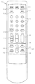
図4は、リモートコマンダ14の外観の例を示すもので、この例のリモートコマンダ14は、操作キーとして、電源キー21、ミューティングキー22、PinPキー23、親子入替キー24、テンキー25、チャンネル番号や放送局名を画面に表示するか否かを切り換えるチャンネル表示キー26、フェイバリット選局キー27、主画面(親画面)用チャンネル順次選択キー28、音量キー29、種々の設定画面を読み出すメニューキー31、アップ/ダウンキー32、エンターキー33、リターンキー34、リセットキー35、その他を備えている。
【0061】
アップ/ダウンキー32は、メニューキー31が押下されて、ディスプレイ6の画面に種々の設定画面が読み出されたときには、その設定画面で選択操作等を行うための操作キーとして働く。また、メニューキー31の押下によるメニューモード以外の通常時は、PinPの子画面用チャンネル順次選択キーとしても働く。
【0062】
CPU101は、このI/Oポート120を介して取り込まれたリモコン信号を解釈し、使用者操作に応じたプログラム対応チャンネルの選局制御、音量制御、PinP合成制御、マルチ小画面表示制御、メニュー等各種重畳表示制御などを行うようにしている。
【0063】
例えば、PinPキー23によりPinP機能が選択されていなければ、切り換え回路4で選択されているチューナ2Mまたはチューナ2Sの一方、例えばチューナ2Mで選局されているプログラム対応チャンネルの番組が単独でディスプレイ10の画面10Dに表示される。
【0064】
そして、このときには、テンキー25を用いてチャンネル番号を直接的に入力操作したり、テンキー25のそれぞれに特定のプログラム対応チャンネルを割り当てている場合に、その対応するテンキーを操作して選局(以下、この選局方法ダイレクト選局という)したり、主画面用(親画面用)チャンネル順次選択キー28を操作することにより、チューナ2Mの選局状態が変わり、ディスプレイ10の画面10Dに表示される番組を他のチャンネルに変更することができるように構成されている。
【0065】
この状態からPinPキー23によりPinP機能が選択されると、チューナ2Mで選局されている番組の画像が主(親)画面として、また、第2のチューナ1Sで選局されている番組の画像が子画面として、それぞれディスプレイ10の画面に表示される。
【0066】
この場合、親画面として表示されている放送番組のチャンネル変更は、テンキー25でダイレクト選局したり、主画面用チャンネル順次選択キー28を操作することにより行え、子画面として表示されている放送番組のチャンネル変更は、アップ/ダウンキー32を操作することより行うことができるように構成されている。
【0067】
この状態から、さらに、親子入替キー24が押下されると、信号切り換え回路4がI/Oポート114からの切り換え制御信号より切り換えられて、チューナ2Sで選局されている番組の画像が親画面として、また、チューナ2Mで選局されている番組の画像が子画面として、それぞれディスプレイ10の画面に表示され、親画面と子画面とが入れ替わる。
【0068】
そして、使用者がフェイバリット選局キー27を押下したときには、前述したようにして、マルチ小画面処理回路7において、5個のプログラム対応チャンネルの小画面P1〜P5の小画像が生成され、図3に示したように、主画面(親画面)に、当該5個の小画面P1〜P5が合成された画像が表示される。
【0069】
この実施の形態の場合、フェイバリット選局キー27を押下することにより起動されるフェイバリット選局機能において選局される5個のマルチ小画像としては、予め使用者がフェイバリットチャンネルを設定しているときには、その設定されたプログラム対応チャンネルの番組の小画像が表示される。そして、使用者によりフェイバリットチャンネルが設定されていないときには、後述のようにしてSRAM105のチャンネル履歴記憶エリアに記憶されている選局チャンネル履歴に基づいて決定された5個のプログラム対応チャンネルがフェイバリットチャンネルとされ、その番組の小画像が、マルチ小画像として表示される。
【0070】
使用者による好みのプログラム対応チャンネルの設定は、メニュー画面から選択されたフェイバリットチャンネルの設定画面において行うことができる。すなわち、リモートコマンダ14のメニューキー31を押下すると、フェイバリットチャンネル設定、その他の設定機能の一覧メニューが表示される。使用者が、その一覧メニューから「フェイバリットチャンネル設定」を選択すると、フェイバリットチャンネル設定画面がディスプレイ10の画面10Dに表示される。
【0071】
すなわち、制御回路100は、ROM103とビデオRAM12を用いて、フェイバリットチャンネル設定画面の表示情報を生成し、ディスプレイコントローラ13を介し、重畳表示処理回路9を通じてディスプレイ10の画面10Dに、当該フェイバリットチャンネルの設定画面を表示する。
【0072】
そこで、使用者は、このフェイバリットチャンネル設定画面において、例えば自分が頻繁に選局すると思われる好みのプログラム対応チャンネルを、リモートコマンダ14を操作して、この実施の形態の場合には、5個選択して設定する。すると、制御回路100は、その設定を受付け、設定された5個のプログラム対応チャンネルの情報を、フェイバリットチャンネルとしてSRAM105に記憶する。この場合、SRAM105に記憶する情報としては、当該チャンネルの選局制御信号であっても良いし、また、対応するリモートコマンダ14からの選局操作情報(ダイレクト選局操作情報)であっても良い。
【0073】
SRAM105には、前記の情報のほか、設定されたプログラム対応チャンネルのチャンネル番号および放送局名も記憶される。
【0074】
さらに、SRAM105には、フェイバリットチャンネルが設定されているか否かの情報、例えば1ビットのフラグFGを記憶する。この場合、フェイバリット選局チャンネルが設定されている場合には、フラグFGは、例えば「1」にして、SRAM1052記憶する。したがって、制御回路100では、このフラグFGが「1」か「0」かで、使用者によりフェイバリットチャンネルが設定されているか否かを判別することができる。
【0075】
使用者によりフェイバリットチャンネルが設定されていないときに、フェイバリット選局キー27が押下されたときには、この実施の形態では、そのキー27の押下の時点よりも前に選局された最近の5個のプログラム対応チャンネルをフェイバリットチャンネルとし、その5個のプログラム対応チャンネルのマルチ小画像を図3に示すように、ディスプレイ10の画面10Dに表示する。このため、SRAM105には、その時点よりも前の少なくとも5個の選局プログラム対応チャンネルの情報が、常に記憶されるように構成されている。この5個のプログラム対応チャンネルに対しても、チャンネル番号および放送局名をもSRAM105に記憶しておく。
【0076】
SRAM105に記憶されたチャンネル番号および放送局名の情報は、マルチ小画面の表示の際に、その各小画面のチャンネル番号、および放送局名を表示するための使用される。なお、このようにチャンネル番号や放送局名をメモリ105に記憶しておかなくても、SRAM105に記憶されているプログラム対応チャンネルに関する選局制御情報や選局操作情報から、リモートコマンダ14の選局操作のときと同様にして、当該チャンネル番号や放送局名を表示する信号を生成して、各小画面に表示させるようにすることもできる。
【0077】
次に、この実施の形態の場合の制御回路100におけるリモートコマンダ14からのリモコン信号の処理ルーチンを、フェイバリット選局機能に関する処理を中心として示すと図5のフローチャートに示すようなものとなる。
【0078】
すなわち、通常、制御回路100は、ステップ201および202において、リモートコマンダ14からのリモコンコマンドの入力待ちの状態にある。そして、ステップ202において、リモコンコマンド入力有りと判別されると、ステップ203に進み、そのリモコンコマンドは、選局に関するキー操作によるものであるか否か判断する。選局に関するキー操作であれば、ステップ204に進んで、そのキー操作がチャンネル番号数値の直接的な選局操作であるダイレクト選局であるか否か判断する。
【0079】
ステップ204での判断の結果、ダイレクト選局でなく、チャンネル順次選択キー28のアップ/ダウン操作による順次選局であるときには、ステップ207に進んで、選局動作を実行し、その後、ステップ201の待ち受け状態に戻る。
【0080】
ステップ204での判断の結果、ダイレクト選局であると判断したときには、ステップ205に進んで、その選局したプログラム対応チャンネルに関する情報(前述したように、選局制御情報あるいは選局操作信号など)をSRAM105に記憶したか否か判断する。
【0081】
ステップ205で、未だ、ダイレクト選局したプログラム対応チャンネルの情報をSRAM105に記憶していないと判断したときには、ステップ206に進み、その選局したプログラム対応チャンネルに関する情報をSRAM105のチャンネル履歴記憶エリアに記憶する。その後、ステップ207に進む。
【0082】
ステップ205でダイレクト選局したプログラム対応チャンネルの情報をSRAM105に記憶したと判断したときには、ステップ207にジャンプする。
【0083】
ステップ207では、前述したように、選局動作を実行し、その後、ステップ201の待ち受け状態に戻る。
【0084】
ステップ204〜206でダイレクト選局したプログラム対応チャンネルのみをチャンネル履歴記憶エリアに記憶するようにしたのは、チャンネル順次選択キー28による選局操作は、使用者が意識して、好みのプログラム対応チャンネルを選択する操作であることは少なく、視聴目的のチャンネルが定まっていないときの操作であることが多いことと、視聴目的のチャンネルが定まっているときには、一般には、ダイレクト選局することが多いことによる。また、チャンネル順次選択キー28による選局操作中のプログラム対応チャンネルには、選局して視聴することを目的としないチャンネルも含まれることも考慮したものである。
【0085】
次に、ステップ203において、リモコンコマンドが選局に関するキー操作のものでないと判断されたときには、ステップ208に進み、フェイバリット選局キー27の押下であるか否か判断する。そして、フェイバリット選局キー27の押下ではないと判断したときには、その他のキー操作によるコマンドであると判断し、ステップ209に進んで、その他のキー操作に応じた処理を行った後、ステップ201の待ち受け状態に戻る。
【0086】
また、ステップ208でフェイバリット選局キー27の押下があったと判断したときには、ステップ210に進んで、フェイバリット選局機能の処理ルーチンが実行される。そして、この処理ルーチンが終了すると、ステップ201に戻り、コマンド待ち受けの状態になる。
【0087】
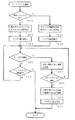
図6は、ステップ210のフェイバリット選局機能の処理ルーチンの一例のフローチャートである。すなわち、まず、このフェイバリット選局機能が起動されると、ステップ301において、使用者によりフェイバリットチャンネルが設定されているか否か、SRAM105のフラグFGにより判断する。
【0088】
ステップ301において、フラグFGにより、使用者によりフェイバリットチャンネルが設定されていると判断したときには、ステップ302に進み、SRAM105から、使用者により設定されている5個あるいはそれ以下の数のフェイバリットチャンネルの情報を読み出す。そして、ステップ303に進み、子画面となる方のチューナの選局状態を、その読み出した1〜複数個のフェイバリットチャンネルを、前述したようにして、200msecの時間毎に順次に変更してサイクリックに選択する状態にする。
【0089】
この結果、図3に示したようなマルチ小画面P1〜P5が、主画面に重畳されて表示される。このとき、前述もしたように、各小画面P1〜P5のそれぞれには、SRAM105に記憶されているチャンネル番号および放送局名も表示されるものである。
【0090】
一方、ステップ301でフェイバリットチャンネルが設定されていないと判断されたときには、ステップ304に進み、SRAM105から、最近、ダイレクト選局した5個のプログラム対応チャンネルの情報を読み出す。そして、ステップ305に進み、子画面となる方のチューナの選局状態を、その読み出した5個のプログラム対応チャンネルを、前述したようにして、200msecの時間毎に順次に変更してサイクリックに選択する状態にする。
【0091】
ステップ303あるいはステップ305の後には、ステップ306に進む。この実施の形態の場合、このフェイバリット選局機能の画面においては、小画面P1〜P5のうちのいづれか一つの小画面を選択することにより、選局ができるように構成されている。すなわち、選択状態にある小画面は図3に示すように、太枠FLで囲われて示され、使用者に通知される。使用者は、リモートコマンダ14のアップ/ダウンキー32を操作することにより、太枠FLにより囲われる小画面を変更することができる。
【0092】
そして、希望するプログラム対応チャンネルの小画面が太枠FLで囲まれている状態で、この実施の形態ではリターンキー34を押下すると、制御回路100では、その太枠FLで囲まれた小画面のプログラム対応チャンネルを主画面として選局するように制御する。つまり、主画面を提供しているチューナに、その選択された小画面のプログラム対応チャンネルの選局制御信号が供給される。
【0093】
ステップ306では、アップ/ダウンキー32が押下されたか否か判断する。そして、アップ/ダウンキー32が押下されたと判断されたときには、ステップ307に進んで、その操作に応じて、選択中のプログラム対応チャンネルの小画面に太枠FLを移動させる。
【0094】
次に、ステップ308に進んで、リターンキー34が押下されたか否か判断する。リターンキー34が押下されていないと判断したときには、ステップ306に戻り、アップ/ダウンキー32が押下されたか否か判断する。リターンキー34が押下されたと判断したときには、ステップ309に進み、太枠FLで選択中の小画面のプログラム対応チャンネルの選局制御信号を、主画面を提供しているチューナに供給する。そして、次のステップ310で、マルチ小画面P1〜P5を消去して、このフェイバリット選局機能を終了する。
【0095】
また、ステップ306でアップ/ダウンキー32の操作ではないと判断したときは、ステップ311に進み、フェイバリット選局機能の強制終了を意味するキー操作、例えばリセットキー35が押下されたか否か判断する。そして、リセットキー35が押下されたと判断したときには、ステップ310に進んで、マルチ小画面P1〜P5を消去し、フェイバリット選局機能を強制終了する。また、ステップ311でリセットキー35が押下されていないと判断したときには、ステップ306に戻る。
【0096】
以上のようにして、フェイバリット選局機能が実現される。図7は、以上のフェイバリット選局機能を表示画面を参照して説明するための図である。この図7の例は、使用者により
▲1▼チャンネル番号38、放送局名「ESPN」
▲2▼チャンネル番号4、放送局名「NBC」
▲3▼チャンネル番号30、放送局名「CNN」
▲4▼チャンネル番号16、放送局名「HBO」
▲5▼チャンネル番号52、放送局名「PBS」
の5個のプログラム対応チャンネルがフェイバリットチャンネルとして設定されている場合である。
【0097】
すなわち、図7Aは、主画面のみにより、チャンネル番号「2」、放送局名「CBS」のテレビ番組を視聴中のディスプレイ10の画面(以下、通常画面という)を示している。
【0098】
この通常画面において、リモートコマンダ14のフェイバリット選局キー27を使用者が押下すると、使用者により予め設定されていた前記▲1▼〜▲5▼のプログラム対応チャンネルの選局に関する情報が、SRAM105から読み出され、前述したようにして、マルチ小画面処理が行われ、ディスプレイ10の画面10Dには、図7Bに示すようなマルチ小画面P1〜P5が、それまでの主画面に重畳されて表示される。
【0099】
このマルチ小画面P1〜P5の表示画面においては、図7Bに示すように、5個の小画面のうちの一つが太枠FLで囲まれている。そして、この状態でリモートコマンダ14で、リターンキー34を押下すると、太枠FLで囲まれた小画面のプログラム対応チャンネルを、主画面として選局する処理を制御回路100は行う。そして、マルチ小画面が消去され、選択された小画面の番組が図7Cに示すように、単独の主画面として画面10Dに表示されるものである。
【0100】
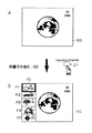
また、使用者によりフェイバリット選局のためのプログラム対応チャンネルが設定されていない場合には、図8に示すようになる。
【0101】
すなわち、図8Aに示す通常画面の状態において、リモートコマンダ14のフェイバリット選局キー27を使用者が押下すると、図8Bに示すようなマルチ小画面がディスプレイ10の画面に表示される。
【0102】
すなわち、マルチ小画面P1〜P5のうち、小画面P1は、現在、主画面で視聴しているプログラム対応チャンネルの放送番組の小画像である。また、小画像P2は、SRAM105のチャンネル履歴記憶エリアに記憶されている、現在より一つ前に選局されていたプログラム対応チャンネルの放送番組の小画像である。同様に、小画像P3、P4、P5は、SRAM105のチャンネル履歴記憶エリアに記憶されている、現在より二つ前、三つ前、四つ前に選局されていたプログラム対応チャンネルの放送番組の小画像である。
【0103】
そして、前述のフェイバリットチャンネルが設定されている場合と同様に、このマルチ小画面の重畳画面において、使用者がアップ/ダウンキー32と、リターンキー34との操作により、希望するプログラム対応チャンネルの小画面を選択すると、そのプログラム対応チャンネルを主画面として選局する状態になる。
【0104】
このように、フェイバリット選局機能の存在を使用者が知らない場合においても、フェイバリット選局キー27が使用者により押下されたときには、SRAM105のチャンネル履歴記憶エリアから、最近、ダイレクト選局された5個のプログラム対応チャンネルが読み出されて、そのときの5個のプログラム対応チャンネルの放送番組内容が小画面P1〜P5としてディスプレイ10の画面に表示される。
【0105】
したがって、フェイバリット選局機能の存在を知らない使用者にも、フェイバリット選局機能の存在を認知させることができる。
【0106】
[他の実施の形態]
以上の実施の形態では、使用者によりフェイバリットチャンネルが設定されていない場合には、最近、ダイレクト選局した5個のプログラム対応チャンネルをフェイバリットチャンネルとして小画面P1〜P5に表示するようにしたが、曜日、時間帯別に、選局状態の継続時間の長い5つのプログラム対応チャンネルを、過去の選局チャンネル履歴からフェイバリットチャンネルを選択して小画面P1〜P5として表示するようにすることもできる。
【0107】
この実施の形態では、チャンネル履歴情報は、一定時間おきにチューナ2Mあるいはチューナ2Sのうちの主画面を提供している方のチューナの選局状態をサンプリングし、その時に選局されているプログラム対応チャンネルをSRAM105のチャンネル履歴記憶エリアに書き込んで記憶するようにする。
【0108】
この実施の形態の場合には、時計回路11からのタイマー情報により、一定間隔毎に割り込み処理として、プログラム対応チャンネルの選局状態をサーチする処理を主画面を提供している方のチューナに対して行い、その時点における当該チューナのプログラム対応チャンネルの選局状態をSRAM105に記憶する。
【0109】
この例のチャンネル履歴情報の作成方法においては、CPU101は、一定時間間隔毎の割り込みであるので、絶対時間情報として開始の時点のみ知れば、それからの時間経過として各サンプリング点の時間を知ることができるので、それぞれのサンプリング時点の時間情報は、SRAM105にそのまま記憶しておく必要はない。
【0110】
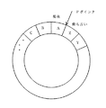
図9および図10は、この場合のチャンネル履歴情報の管理方法のイメージ図を示すもので、SRAM105のチャンネル履歴記憶エリアをイメージ化したものである。図9A、図9Bおよび図10において、矢印で示す位置は、ポインタPの位置である。このポインタPは、現在、記憶エリアのどの時点であるかを示すものであって、図10に示すように、イメージ的にはSRAM105のチャンネル履歴記憶エリアはチャンネル履歴データとしては、リング構造の管理を行うものである。
【0111】
この例においては、現時点よりも以前のn(nは2以上の整数)週間のチャンネル履歴情報をSRAM105に常に記憶するようにするもので、n週間前よりも古い情報を捨てながら、順次に新しいチャンネル履歴情報を逐次に蓄積するようにするものである。
【0112】
すなわち、この例においては、例えば10分毎に主画面を提供している方のチューナに対してチャンネル履歴取得のための走査を行い、その結果得られたチャンネル履歴の情報は、図9に示すように、10分間隔で連続したアドレス空間によって管理される。そして、図10に示すようなリング構造の記憶エリアがいっぱいになったとき、図9Bに示すように、最も古いチャンネル履歴データを破棄し、新規に取り込んだ現在のチャンネル履歴データを、記憶エリアに格納していくような記憶方法を取る。
【0113】
この実施の形態の場合、このSRAM105に記憶されるチャンネル履歴データは、前述したように少なくとも複数週間分にわたって記憶される。そして、CPU101は、SRAM105のこのチャンネル履歴データを、曜日毎に管理できるようになっている。これは、10分間隔であれば、その144倍が1日分であり、その7倍が一週間であることから、チャンネル履歴データの個数を計数するだけで簡単に管理することができるからである。
【0114】
この場合、前述した割り込み処理によるチャンネル履歴データの取り込みは、××時01分、××時11分、××時21分、××時31分などのように、実際に番組が始まった時間に起動される。
【0115】
SRAM105のチャンネル履歴データの記憶エリアへのチャンネル履歴データの記憶に先立ち、このエリアは初期化される。つまりクリアされる。これと同時に履歴記憶用の前記ポインタ位置も、初期化されることになる。この初期化によって、過去の履歴情報はクリアされるので、この初期化の設定は、例えばテレビ受信機において、リモコンデータとプログラム対応チャンネルとの割り付けや、時計回路11への現在時刻の登録などの契機に行われるものである。
【0116】
ここで、リモコンデータとプログラム対応チャンネルとの割り付けとは、例えば、ユーザがリモートコマンダ14によるダイレクト選局のための数字キーを、いずれかのプログラム対応チャンネル(放送局)に割り付けるような操作のことである。一般に、このダイレクトチャンネル設定などはテレビ受信機の購入時に行われるが、適宜、ユーザによって行われる場合もある。
【0117】
次に、この例の場合のチャンネル履歴の記録動作について、図11のフローチャートを参照しながら説明する。
すなわち、この例の場合、前述したような実際に放送が行なわれていると考えられる10分おきの時間で割り込みがかかると(ステップS0)、このチャンネル履歴データの取り込み処理ルーチンが起動される。
【0118】
そして、次のステップS1において、SRAM105のチャンネル履歴記憶エリアにおいてポインタを更新する。このポインタの更新は、新しいデータエリアの確保になり、このステップS1では、当該新たに確保されたデータエリアをヌルクリア(0にする)する処理も同時に行なう。この例の場合、SRAM105のチャンネル履歴記憶エリアは、前述したようにリング状の管理が行われているので、リング状のチャンネル履歴データエリアがいっぱいになった後には、ポインタの更新の処理には、最も古いチャンネル履歴データの破棄を伴うことになる。
【0119】
そして、この場合、ポインタの更新による新しいデータエリアのアドレスが、リング状メモリエリアの最終アドレスを越えてしまう場合には、ポインタを先頭アドレスにリセットする。
【0120】
この場合、テレビ受信機の主電源スイッチがオンである間は、ステップS0を通じての、この例の場合には、10分毎に起動がかかるが、テレビ受信機の主電源スイッチがオフである間は、この図11の処理ルーチンへの割り込み処理は起動されない。そこで、この例では、時計回路11は別電源で動作しているので、その時間情報を用いて、このステップS1においては、次の主電源オンの後の最初の割り込みタイミングで、主電源オフである間に行なわれるべきチャンネル履歴記憶エリアの更新処理が行なわれる。
【0121】
すなわち、この例では、SRAM105に主電源スイッチがオフされる直前に行なわれた割り込みタイミングの時間を保持するようにしておく。そして、その後、テレビ受信機の主電源スイッチがオンとされ、割り込みタイミングとなったときには、SRAM105の前記主電源スイッチがオフされる直前に行なわれた割り込みタイミングの時間を参照して、その間に行なわれるべき割り込み回数を検知し、その割り込み回数分のポインタの更新と、更新される個数分の各データエリアのすべてをヌルクリアするようにする。そして、現時点における割り込みタイミングに対応するデータエリアまでの更新を行なう。
【0122】
こうして、ポインタの更新と新しいデータエリアの確保が行われると、ステップS2に進み、現在、放送を視聴中か否かをチェックする。この処理は、図1には図示しなかったが、テレビ受信機が外部入力端子を備えており、例えばVTR等からの外部ビデオ信号を視聴している状態を放送の視聴としないようにするために行う。
【0123】
そして、放送波の視聴が行われている場合には、ステップS2からステップS3に進み、そのときに主画面とされている方のチューナで選択されているプログラム対応チャンネルの情報を新しく確保したデータエリアに記憶する。この記憶するプログラム対応チャンネルの情報内容としては、チャンネル番号でも良いし、あるいは前記チューナに供給された選局制御データであっても良い。
【0124】
一方、放送波の視聴が行なわれていないとステップS2で判断されたときには、ステップS4に進み、新しく確保されたデータエリアに「0」をセットする。なお、この例では、前述のステップS1でのテレビ受信機の主電源オフの間に対する処理により、テレビ受信機に主電源が投入されていない場合も、同様にしてチャネル履歴のデータエリアには「0」が保持されており、この状態も、テレビ放送の視聴が行われていない状態とされることになる。
【0125】
ステップS3あるいはステップS4の処理を終了した後には、ステップS5からこのルーチンを終了する。
【0126】
こうして、この例では、SRAM105の複数週間分のチャンネル履歴記憶エリアに、10分毎に、その時点で視聴されている放送波のプログラム対応チャンネルの情報が、新しい履歴として残されていく。そして、前述もしたように、この複数週間分のチャンネル履歴エリアがいっぱいであるときには、古い履歴を捨てながら、新しいチャンネル履歴情報が逐次書き込まれてゆく。
【0127】
図12は、1日分のチャンネル履歴情報を、テーブルの形式で表した例を示すものであり、各チャンネル履歴データエリアDchには、この例ではプログラム対応チャンネル番号の情報が記憶されている。なお、図12でチャンネル履歴データエリアDchの左横に示した時刻は、各チャンネル履歴データの取り込み時刻であって、この例の場合には、これらの時刻は、前述したように、データエリアDchに記憶する必要はない。
【0128】
この実施の形態の場合には、10分単位でチャンネル履歴が更新されるので、1日では6×24=144個の履歴データが格納される。したがって、一週間では144×7=1008個の履歴データが記録されることになる。この場合に、1つのチャンネル履歴データを1バイト長とすると、1週間で1008バイトとなる。前述したように、複数週間分の履歴を取る必要があるので、1008バイトの整数倍分のメモリエリアが、SRAM105にチャンネル履歴記憶エリアとして設定されることになる。
【0129】
前述もしたように、この例の場合には、チャンネル履歴データのテーブルは、図12に示すようなものであり、1日および1週間当たりの履歴データ数が定まっているので、現時点から1週間前、2週間前のように相対的な時間関係にあるデータエリアがわかれば、過去の同一時刻のチャンネル履歴データを容易に得ることができる。したがって、SRAM105に記憶するチャンネル履歴情報としては、前述したように、各履歴データの取り込み時刻の絶対時間の情報は必要ではない。
【0130】
なお、以上の例では、時間経過に伴ってポインタを一定量ずつ更新するようにしたので、テレビ受信機の主電源がオフである間は、前述したように、ポインタの更新とデータエリアのヌルクリアが繰り返されることになる。そこで、テレビ受信機の主電源スイッチがオフからの、次の主電源オン時に、この主電源オフのの間に行なわれるべき割り込み回数を検知し、チャンネル履歴メモリエリアに記録するデータとしては、その回数分のヌルデータの連続を表すコード、例えば16進表示で[FF**](**はヌルデータの個数を表す)を記録するようにして、メモリエリアの節約を計るようにすることもできる。
【0131】
なお、以上の例では、10分間隔で、チャンネル履歴情報の取り込みを行なうようにしたが、15分毎、30分毎でもよく、また、チャンネル履歴情報のメモリエリアが十分に大きい場合には、1分毎や5分毎でもよい。ただし、番組の放送時間が30分または60分単位であることから、この例のように周期的にチャンネル履歴情報の取り込みを行なう場合には、8分毎や9分毎などの単位外れが生じるようなタイミングでないほうがよい。
【0132】
また、常に一定の時間間隔で、チャンネル履歴情報の取り込みを行なうのではなく、一般に視聴率の高いプライムタイムと呼ばれる時間帯は細かく分けるようにしてもよい。
【0133】
この実施の形態では、以上のようにしてSRAM105に記憶した過去のチャンネル履歴の情報から、曜日および時間帯別に、ユーザー選局して視聴している時間の長いフェイバリット選局チャンネルを、この例では5個決定し、それをSRAM105に、各曜日ごとにテーブルとして記憶しておくようにする。
【0134】
すなわち、図13は、この各曜日毎のテーブルのうちの例えば月曜日の、例えば30分ごとの時間帯別のフェイバリット選局チャンネルの例を示すテーブルである。この図13のテーブルは、例えば同曜日、この場合には月曜日の1日が経過すると、当該曜日の各時間帯の5個のフェイバリット選局チャンネルが更新される。
【0135】
今、例えば、SRAM105の月曜日の午前6時から午前6時30分の時間帯の5個のフェイバリット選局チャンネルが、図13に示すように、
▲1▼チャンネル番号87、放送局名「WEA」
▲2▼チャンネル番号27、放送局名「TRF」
▲3▼チャンネル番号2、放送局名「CBS」
▲4▼チャンネル番号6、放送局名「ABC」
▲5▼チャンネル番号28、放送局名「TBS」
と決定されており、また、ユーザーによりフェイバリット選局チャンネルが設定されていない場合を想定する。
【0136】
この場合に、図14Aに示すような通常画面の状態において、ユーザーが午前6時にリモートコマンダ14のフェイバリット選局キー27を押下した場合には、図14Bに示すようなマルチ小画面P1〜P5がディスプレイ10の画面10Dに表示され、同時間帯で過去に良く視聴している5個の放送番組がユーザーに通知される。
【0137】
したがって、ユーザーはフェイバリット選局機能の存在を知るとともに、過去に良く視聴している番組の中から、その時間帯で視聴したい番組を選局をすることができる。このため、連続ドラマや朝の天気予報、交通情報などを見逃しなく、視聴することができるようになる。そして、この実施の形態の場合には、それぞれの時間帯、曜日でのフェイバリット選局チャンネルの記憶内容は、それまでのチャンネル履歴によって更新されるので、シーズンごとに新番組に変更になっても、その変更に自動的に合致したフェイバリット選局チャンネルとなる。
【0138】
なお、この実施の形態では、特定の曜日毎の時間帯毎によって小画面P1〜P5として表示するフェイバリットチャンネルを決定したが、各曜日毎にフェイバリットチャンネルを決定したり、また、曜日に関係なく、時間帯毎のみにより、フェイバリットチャンネルを決定するようにしてもよい。
【0139】
[小画面表示の他の例]
主画面に小画面を重畳させて表示するのではなく、図15に示すように、ディスプレイ10の画面10Dの全部を使用して、小画面を表示するようにすれば、フェイバリットチャンネルとして表示できるチャンネル数を増加することができるとともに、各小画面の大きさを大きくすることができる。小画面の大きさを大きくすることができるので、これらの小画面の中からユーザーが選局をするときに、番組内容を十分に把握して、選局を行うことが容易になる。
【0140】
また、小画面に番組内容の画像を表示するのではなく、図16に示すように、プログラム対応チャンネルのチャンネル番号と、放送局名のみを表示するようにすれば、主画面に小画面を重畳する場合においても、さらにより多くのプログラム対応チャンネルをフェイバリットチャンネルとして画面に表示することが可能になる。
【0141】
[他の実施の形態]
以上の例は、フェイバリット選局チャンネルがユーザーにより設定されていないときにフェイバリット選局キー27がユーザーに操作されたときに、過去のチャンネル選局履歴からテレビ受信機がフェイバリットチャンネルを自動的に設定して、それをマルチ小画面としてディスプレイ画面に表示するようにしたが、この実施の形態では、図17に示すように、リモートコマンダ14のフェイバリット選局キーをシーソー型のキー41として、マニュアルと、自動(オート)との両方を選択できるようにする。
【0142】
そして、キー41により、マニュアルが選択されたときには、ユーザーにより設定されたフェイバリット選局チャンネルをメモリから読み出し、当該読み出されたチャンネルの小画面を前述の実施の形態の場合と同様にして形成してディスプレイ画面に表示するようにする。
【0143】
また、キー41により、自動が選択されたときには、前述したように、チャンネル選局履歴から制御回路100でフェイバリットチャンネルを自動的に決定し、その決定されたチャンネルの小画面を前述の実施の形態の場合と同様にして形成してディスプレイ画面に表示するようにする。
【0144】
この実施の形態の場合には、キー41によりマニュアルを選択した場合、チャンネル設定が無ければマルチ小画面が表示されないが、キー41には、自動のポジションもあるので、この自動のポジションの使用者の選択により、フェイバリット選局機能の存在を認識することができる。そして、フェイバリット選局機能を認識した後には、マニュアルと自動とを適宜選択してフェイバリット選局機能を利用することにより、ユーザーのフェイバリット選局機能のさらなる有効利用を計ることができる。
【0145】
なお、一つのシーソーキー41ではなく、マニュアルのフェイバリット選局キーと、自動のフェイバリット選局キーを、リモートコマンダ14にそれぞれ設けるようにしても、もちろん良い。
【0146】
[放送受信装置の他の例]
以上の例は、地上放送波のテレビ受信機の場合であるが、以下に説明する例は、米国で放送が開始されたデジタル衛星放送に、この発明を適用した場合である。上述したアナログ地上放送では、日本の場合、例えば6MHz毎に周波数帯域が分割され、各分割周波数帯域を放送伝送チャンネルとして、1つの放送伝送チャンネルに1つの放送局、つまり、プログラム対応チャンネルが1対1に対応するようにされていたので、1つの放送伝送チャンネルを選択することで、特定の放送局(プログラム対応チャンネル)の番組を選択受信することができる。
【0147】
これに対して、この例のデジタル衛星放送においては、伝送チャンネルと、プログラム対応チャンネル(この例では放送局に対応、以下同じ)とは一致せず、チャンネルは特定の周波数帯域を示すものとはならない。これは、放送周波数帯域を有効利用するためである。
【0148】
すなわち、デジタル衛星放送では、映像や音声は、MPEG1あるいはMPEG2などの方式によって、データ圧縮して放送するものであり、画面の動きの少ない番組であれば、放送する情報量は少なてよく、一方、スポーツ番組などの動きの激しい映像の場合には、これを画質を落とさずに放送するためには、情報量が多く必要である。そこで、ある番組を放送するとき、放送する情報量に応じて使用する放送周波数あるいは周波数群を変更することにより、放送周波数帯域を有効利用するようにしているのである。つまり、情報量が少ない場合には、複数の番組を、1つの周波数あるいは1つの周波数群で放送が可能であり、情報量が多量である場合には、1つの番組であっても複数の周波数あるいは複数の周波数群を使用して放送する必要がある場合もある。
【0149】
デジタル衛星放送では、このように、プログラム対応チャンネルに対して、放送波の使用状況が固定的でないので、ある特定の周波数群の放送信号として、他の放送波周波数あるいは周波数群が、プログラム対応チャンネルに対してどのように使用されているかについての情報を放送するようにしている。この明細書では、これをインデックスチャンネルと呼ぶ。
【0150】
このインデックスチャンネルの情報には、番組タイトルなども含む放送番組予定表の情報も含まれる。このため、デジタル衛星放送では、プログラム対応チャンネルと時間が分かれば、その放送番組のタイトルなどもインデックスチャンネルから得ることができる。そこで、この番組タイトル情報をSRAM105にチャンネル履歴情報に共に記憶しておけば、受信者に対して、プログラム対応チャンネルや放送局名だけでなく、その番組タイトルを、小画面に番組の情報として報知することができる。
【0151】
なお、デジタルテレビ放送の場合、チューナは2個設ける必要がなく、1個のプログラムセレクタと2個のデコーダでこれを置き換えることができる。そして放送波の伝送チャンネルと、番組を表すプログラム対応チャンネルとは一致しないので、この場合には選局情報としては、プログラム対応チャンネルをチャンネル履歴情報として記憶することになる。
【0152】
なお、以上の例は、いずれもテレビ放送波を受信する装置に、この発明による選局方法および装置を適用した場合であるが、この発明は、ケーブルテレビ放送や、ラジオ放送を受信する場合にも適用できることはいうまでもない。
【0153】
【発明の効果】
以上説明したように、この発明によれば、フェイバリットチャンネルを設定して、フェイバリット選局機能を愛用している使用者には、その機能を保証することができるとともに、フェイバリット選局機能の存在を知らずに、フェイバリットチャンネルの設定を行っていないユーザーにも、その機能の存在を認知させることができる。
【0154】
また、マニュアル/自動のフェイバリット選局機能をキーにより選択できるようにした場合には、フェイバリットチャンネルをユーザーが設定せずともフェイバリット選局機能を利用することができる。
【0155】
したがって、この発明によるテレビ受信機によれば、ユーザーは、フェイバリット選局機能を確実に認知して、有効に活用するようになるため、テレビ受信機の総体的な使い勝手を向上させることができる。
【図面の簡単な説明】
【図1】この発明による選局装置の一実施の形態のブロック図である。
【図2】この発明による選局装置の一実施の形態の要部のブロック図である。
【図3】この発明による選局方法および選局装置の実施の形態におけるフェイバリット選局機能の画面表示の例を示す図である。
【図4】この発明による選局装置の一実施の形態に用いられるリモートコマンダの例を示す図である。
【図5】この発明による選局方法および選局装置の実施の形態における要部の処理ルーチンの例を示す図である。
【図6】この発明による選局方法および選局装置の実施の形態におけるフェイバリット選局機能の処理ルーチンの例を示す図である。
【図7】この発明による選局方法および選局装置の実施の形態におけるフェイバリット選局機能を説明するための図である。
【図8】この発明による選局方法および選局装置の実施の形態におけるフェイバリット選局機能を説明するための図である。
【図9】この発明による選局装置の一実施の形態に用いられるチャンネル履歴データの管理方法を説明するための図である。
【図10】この発明による選局装置の一実施の形態に用いられるチャンネル履歴データの管理方法を説明するための図である。
【図11】この発明による選局装置の一実施の形態に用いられるチャンネル履歴データの記憶手順を示すフローチャートである。
【図12】この発明による選局装置の一実施の形態に用いられるチャンネル履歴データの1日分を説明するための図である。
【図13】この発明による選局装置の一実施の形態においてチャンネル履歴から決定される特定の曜日のフェイバリットチャンネルを説明するための図である。
【図14】この発明による選局方法および選局装置の実施の形態におけるフェイバリット選局機能を説明するための図である。
【図15】この発明による選局方法および選局装置の実施の形態におけるフェイバリットチャンネルの画面表示の他の例を示す図である。
【図16】この発明による選局方法および選局装置の実施の形態におけるフェイバリットチャンネルの画面表示の他の例を示す図である。
【図17】この発明による選局装置の他の実施の形態で使用するリモートコマンダの例を示す図である。
【符号の説明】
2M チューナ
2S チューナ
11 時計回路
14 リモートコマンダ
27 フェイバリット選局キー
28 チャンネル順次選択キー
31 メニューキー
32 アップ/ダウンキー
34 リターンキー
41 シーソー型のフェイバリット選局キー
100 制御回路
101 CPU
103 ROM
105 チャンネル履歴情報記憶用のSRAM[0001]
BACKGROUND OF THE INVENTION
The present invention, for example, in a television receiver or radio receiver, allows a receiver to easily select a program that is frequently viewed from a large number of program-compatible channels that can be received. And a channel selection device.
[0002]
Here, in this specification, a program-compatible channel indicates a channel number assigned to a broadcasting station, and is distinguished from a transmission channel assigned a number for each frequency band obtained by dividing a transmission band of a broadcast wave. . By the way, for example, in the current terrestrial television broadcasting in Japan, the number of the transmission channel and the number of the channel corresponding to the program usually match, but in the digital television broadcasting started broadcasting in North America, one transmission A program of a plurality of broadcast stations is transmitted to a channel at the same time, or a program of one broadcast station is broadcast on different transmission channels.
[0003]
[Prior art]
There are many program-compatible channels for TV and radio broadcasts. For example, in the digital television broadcast described above, 150 program-compatible channels can be broadcast. However, the program-compatible channels that are frequently viewed vary depending on the user, but are often limited to a specific plurality of program-compatible channels.
[0004]
Therefore, for example, when selecting a channel for television broadcasting, it is not necessary to select a channel from among all the channels that can be viewed, but among a plurality of favorite channels that are preset by the user and have a high channel selection rate. A channel selection method called a so-called favorite channel selection function has been proposed, which enables channel selection from the beginning.
[0005]
That is, a television receiver adopting this channel selection method has a setting screen for a favorite program-corresponding channel (hereinafter referred to as “favorite channel”). Select one or more favorite channels that you expect to watch frequently. Then, the television receiver stores the set favorite channel in the built-in memory.
[0006]
Then, when a key operation for selecting the function of this channel selection method is performed with a remote controller or the like, the television receiver reads one to a plurality of set favorite channels from the built-in memory, for example, at that time point, The broadcast content of the read favorite channel is displayed together with the channel number as a plurality of small screens on the screen by using a technique as disclosed in, for example, Japanese Patent Laid-Open No. 56-136089.
[0007]
The user can refer to a plurality of small screens displayed on this screen and select a program-corresponding channel that he / she wants to view from among them.
[0008]
[Problems to be solved by the invention]
However, the channel selection method using the above-described favorite channel selection function can be used effectively only after the user selects and calls the favorite channel setting screen from, for example, a menu and sets one or more favorite channels. Can not. In other words, it is recognized that there is a channel selection function based on this channel selection method, and only a user who has set a favorite channel can use the channel selection function. May not even allow the user to recognize the existence or effectiveness of the channel selection function.
[0009]
Some users find it troublesome to set a favorite channel.
[0010]
In view of the above points, the present invention is capable of identifying one to a plurality of program-corresponding channels that are likely to be selected by the user regardless of whether the user has set a favorite channel or not. It is an object of the present invention to provide a channel selection method and a channel selection apparatus that are displayed on the screen and can be selected.
[0011]
[Means for Solving the Problems]
In order to solve the above problems, in the present invention,
One to a plurality of favorite program-corresponding channels set in advance by the user are stored in the set channel first storage unit, and the favorite program correspondence is stored from the first storage unit in response to a predetermined key input. The channel is read and the user can identify the channel corresponding to the favorite program. As described above, the display using a plurality of small screens together with the main image of the program corresponding to the channel corresponding to the program selected by the user In the channel selection method for displaying on the display screen, the user selects a channel from among the one or more favorite program-compatible channels by performing a channel selection operation on the display screen.
A second storage unit for channel selection channel history storage is provided, and the past selection state of the program-corresponding channel is stored in the second storage unit.
When the predetermined key input is accepted, it is determined whether or not the favorite program-corresponding channel is preset in the first storage unit, and when the favorite program-corresponding channel is not set, A channel corresponding to the program based on the past channel selection channel history stored in the second storage unit The plurality of small screens in the order based on the channel selection channel history. And on this display screen, the user's tuning operation is accepted.
It is characterized by that.
[0012]
The channel selection device according to the present invention is
Depending on the tuning control signal, From broadcast waves A channel selection means for selecting a signal of a desired channel corresponding to a program;
A channel selection control signal generating means for generating the channel selection control signal in response to a user channel selection operation;
Setting channel storage means for storing one to a plurality of program-corresponding channels set by the user;
Channel history storage means for storing past selection states of the program-compatible channels by the channel selection means;
When there is a predetermined key input, it is determined whether or not there is a program-corresponding channel set by the user in the setting channel storage means, and when there is a set program-corresponding channel, the setting channel storage means The user can identify the program-compatible channel stored in As described above, the display using a plurality of small screens together with the main image of the program corresponding to the channel corresponding to the program selected by the user When there is no set program-corresponding channel displayed on the display screen, the program-corresponding channel based on the past channel selection channel history stored in the channel history storage means is displayed. The plurality of small screens in the order based on the channel selection channel history. Control means to display and
The channel selection operation of the user includes an operation of selecting a program-compatible channel from the display on the display screen.
[0014]
According to the present invention configured as described above, even when a user does not set a favorite channel, the channel corresponding to the program selected in the past read from the channel history storage unit is displayed on the display screen. Is done. Therefore, even if the user does not set the desired channel for multiple programs, the user can select the channel from among the multiple channels that are likely to be selected by the user. The tuning function can work effectively.
[0015]
DETAILED DESCRIPTION OF THE INVENTION
Hereinafter, an embodiment of a channel selection apparatus according to the present invention will be described with reference to the drawings, taking as an example a television receiver for receiving analog television broadcast waves using terrestrial waves.
[0016]
FIG. 1 is a block diagram of the television receiver of this embodiment. This television receiver has a so-called picture-in-picture (hereinafter referred to as PinP) function that can display a sub-screen in a small area of a part of the display screen, and includes one to a plurality of favorite channels. In order to realize a favorite channel selection function for selecting a channel from the inside, a function of displaying a plurality of small screens on a part of the display screen (this function is hereinafter referred to as a multi-small screen function) is adopted.
[0017]
In FIG. 1, broadcast radio waves received by an
[0018]
In this case, the channel selection control signal is generated by the
[0019]
These tuners 2M and 2S convert the broadcast wave signal of the selected program-corresponding channel into a video intermediate frequency signal and supply it to the video intermediate frequency amplification and detection circuits 3M and 3S, respectively. In these circuits 3M and 3S, the intermediate frequency signal is amplified and the video signal and the audio signal are demodulated. In FIG. 1, for simplicity of explanation, the audio signal system after demodulation is omitted.
[0020]
The demodulated video signals from the video intermediate frequency and detection circuits 3M and 3S are supplied to the
[0021]
In the video
[0022]
The video
[0023]
The video signal to be input to the video
[0024]
That is, the multi-small
[0025]
In the case of this embodiment, in the multi-small screen function, the small screens of broadcast programs of five different program-corresponding channels are shown as small screens P1, P2, P3, P4, and P5 in the screen display of FIG. The main screen MP can be displayed on the
[0026]
The
[0027]
The channel number and broadcast station
[0028]
Then, as shown in FIG. 3, the program-corresponding channel numbers and broadcast station names of the programs shown on each small screen are displayed in the small screens P1 to P5.
[0029]
In the case of this embodiment, the
[0030]
Then, the tuner is in the channel selection state of the favorite channel by the channel selection control signal given at that time for every 200 msec. At this time, the
[0031]
The
[0032]
In synchronization with the change of channel selection, the small screen memory to be written out of the five
[0033]
The
[0034]
The image data read from the
[0035]
Since the multi-small screens P1 to P5 are displayed as described above, what is displayed on each of the small screens P1, P2,..., P5 of the
[0036]
And since the channel number and the broadcast station name are superimposed on each of the small screens P1 to P5 in FIG. 3, the user can determine which program-corresponding channel and broadcast station name the image of each small screen is. Is easy to understand.
[0037]
The
[0038]
For example, when the PinP function or the favorite channel selection function is not activated, the
[0039]
When the PinP function is activated, the video signal from the video
[0040]
Further, when the favorite channel selection function is activated, the video signal processing for the main screen is performed in the area where the multi-small screen is displayed on the screen by the composite signal from the
[0041]
As will be described later, the superimposing
[0042]
Next, the
[0043]
As described above, the
[0044]
Various programs are stored in the
[0045]
The
[0046]
For example, a tuning control signal is supplied from the
[0047]
[0048]
Further, the time of the
[0049]
In this specification, the channel history information refers to the selection status of the channel corresponding to the program in the tuner viewed as the main screen stored in the memory (SRAM 105) in association with the day of the week and the time. Information (that is, information indicating which program-compatible channel was viewed on the main screen at a certain time on a certain day in the past, for example, information for a plurality of weeks in this example).
[0050]
The
[0051]
The video
[0052]
The sub-screen video
[0053]
As described above, the multi-small
[0054]
The
[0055]
Further, a control signal indicating whether or not to perform superimposed display is supplied to the superimposed
[0056]
For this superimposed display, a
[0057]
In this case, font data and image data of characters and symbols necessary for superimposed display are stored in the
[0058]
As the superimposed display, an overlay process such as so-called superimpose is performed and displayed on the
[0059]
In the television receiver of this example, various controls are performed by the
[0060]
FIG. 4 shows an example of the external appearance of the
[0061]
When the
[0062]
The
[0063]
For example, if the PinP function is not selected by the
[0064]
At this time, when the channel number is directly input using the
[0065]
In this state, when the PinP function is selected by the
[0066]
In this case, the channel of the broadcast program displayed as the main screen can be changed by directly selecting a channel with the
[0067]
From this state, when the parent-
[0068]
Then, when the user presses the favorite
[0069]
In the case of this embodiment, five multi-small images selected by the favorite channel selection function activated by pressing the favorite
[0070]
The user can set a favorite channel corresponding to a program on the favorite channel setting screen selected from the menu screen. That is, when the
[0071]
That is, the
[0072]
Therefore, in this embodiment, the user operates the
[0073]
In addition to the above information, the
[0074]
Further, the
[0075]
When the favorite
[0076]
The channel number and broadcast station name information stored in the
[0077]
Next, the processing routine of the remote control signal from the
[0078]
That is, normally, the
[0079]
As a result of the determination in
[0080]
As a result of the determination in
[0081]
If it is determined in
[0082]
If it is determined in
[0083]
In
[0084]
Only the channel corresponding to the program directly selected in
[0085]
Next, when it is determined in
[0086]
If it is determined in
[0087]
FIG. 6 is a flowchart of an example of a processing routine of the favorite channel selection function in
[0088]
In
[0089]
As a result, multi-small screens P1 to P5 as shown in FIG. 3 are displayed superimposed on the main screen. At this time, as described above, the channel numbers and the broadcasting station names stored in the
[0090]
On the other hand, when it is determined in
[0091]
After
[0092]
In this embodiment, when the
[0093]
In
[0094]
Next, the process proceeds to step 308 to determine whether or not the
[0095]
If it is determined in
[0096]
The favorite channel selection function is realized as described above. FIG. 7 is a diagram for explaining the above-described favorite channel selection function with reference to the display screen. This example of FIG.
(1)
(2)
(3)
(4)
(5)
This is a case where the five program-corresponding channels are set as favorite channels.
[0097]
That is, FIG. 7A shows a screen (hereinafter, referred to as a normal screen) of the
[0098]
When the user depresses the favorite
[0099]
In the display screens of the multi-small screens P1 to P5, as shown in FIG. 7B, one of the five small screens is surrounded by a thick frame FL. When the
[0100]
Further, when the user does not set a program-corresponding channel for favorite channel selection, it becomes as shown in FIG.
[0101]
That is, when the user presses the favorite
[0102]
That is, among the multi-small screens P1 to P5, the small screen P1 is a small image of the broadcast program of the channel corresponding to the program currently viewed on the main screen. Further, the small image P2 is a small image of a broadcast program of a channel corresponding to a program that has been selected immediately before the current time stored in the channel history storage area of the
[0103]
As in the case where the favorite channel is set, the user can operate the up / down key 32 and the
[0104]
As described above, even when the user does not know the existence of the favorite channel selection function, when the favorite
[0105]
Therefore, a user who does not know the existence of the favorite channel selection function can recognize the existence of the favorite channel selection function.
[0106]
[Other embodiments]
In the above embodiment, when the favorite channel is not set by the user, the five program-corresponding channels selected directly recently are displayed as the favorite channels on the small screens P1 to P5. Depending on the day of the week and the time zone, five program-corresponding channels having a long tuning duration can be displayed as small screens P1 to P5 by selecting a favorite channel from the past channel selection history.
[0107]
In this embodiment, the channel history information samples the tuning status of the tuner that provides the main screen of the tuner 2M or tuner 2S at regular intervals, and corresponds to the program selected at that time. The channel is written and stored in the channel history storage area of the
[0108]
In the case of this embodiment, the process of searching for the channel selection state of the program-compatible channel is performed as an interrupt process at regular intervals based on the timer information from the
[0109]
In the channel history information creation method of this example, since the
[0110]
FIG. 9 and FIG. 10 show an image diagram of the management method of the channel history information in this case. The channel history storage area of the
[0111]
In this example, channel history information for n weeks (n is an integer of 2 or more) weeks before the current time is always stored in the
[0112]
That is, in this example, for example, the tuner that provides the main screen is scanned every 10 minutes to acquire the channel history, and the channel history information obtained as a result is shown in FIG. Thus, it is managed by an address space continuous at 10-minute intervals. When the storage area of the ring structure as shown in FIG. 10 is full, as shown in FIG. 9B, the oldest channel history data is discarded, and the newly acquired current channel history data is stored in the storage area. Take a storage method like storing.
[0113]
In this embodiment, the channel history data stored in the
[0114]
In this case, the acquisition of the channel history data by the interrupt processing described above is the time when the program actually started, such as XX hour 01 minute,
[0115]
Prior to storing the channel history data in the channel history data storage area of the
[0116]
Here, the assignment of the remote control data and the program-corresponding channel is, for example, an operation in which the user assigns a numeric key for direct channel selection by the
[0117]
Next, the channel history recording operation in this example will be described with reference to the flowchart of FIG.
That is, in the case of this example, when an interruption occurs every 10 minutes that is considered to be actually broadcast as described above (step S0), this channel history data capturing process routine is started.
[0118]
In the next step S1, the pointer is updated in the channel history storage area of the
[0119]
In this case, if the address of the new data area by updating the pointer exceeds the final address of the ring-shaped memory area, the pointer is reset to the head address.
[0120]
In this case, while the main power switch of the television receiver is on, it starts up every 10 minutes through the step S0 in this example, while the main power switch of the television receiver is off. The interrupt processing to the processing routine of FIG. 11 is not activated. Therefore, in this example, since the
[0121]
In other words, in this example, the
[0122]
When the pointer is updated and the new data area is secured in this way, the process proceeds to step S2 to check whether the broadcast is currently being viewed. Although this process is not shown in FIG. 1, the television receiver has an external input terminal so that, for example, viewing of an external video signal from a VTR or the like is not viewed in broadcasting. To do.
[0123]
Then, when the broadcast wave is being viewed, the process proceeds from step S2 to step S3, in which data for the program-corresponding channel selected by the tuner that is the main screen at that time is newly secured data. Remember in the area. The information content of the program-corresponding channel to be stored may be a channel number or channel selection control data supplied to the tuner.
[0124]
On the other hand, if it is determined in step S2 that the broadcast wave is not being viewed, the process proceeds to step S4, where “0” is set in the newly secured data area. In this example, even when the main power is not turned on by the processing during the main power-off of the television receiver in the above-described step S1, the data area of the channel history is similarly “ “0” is held, and this state is also a state in which the television broadcast is not viewed.
[0125]
After finishing the process of step S3 or step S4, this routine is complete | finished from step S5.
[0126]
In this way, in this example, the program history channel information of the broadcast wave being viewed at that time is left as a new history every 10 minutes in the channel history storage area of the
[0127]
FIG. 12 shows an example in which the channel history information for one day is expressed in the form of a table. In this example, information on the channel number corresponding to the program is stored in each channel history data area Dch. Note that the time shown on the left side of the channel history data area Dch in FIG. 12 is the fetch time of each channel history data. In this example, these times are the data area Dch as described above. There is no need to remember.
[0128]
In this embodiment, since the channel history is updated every 10 minutes, 6 × 24 = 144 history data are stored in one day. Therefore, 144 × 7 = 1008 history data is recorded in one week. In this case, if one channel history data is 1 byte long, it becomes 1008 bytes per week. As described above, since it is necessary to take a history for a plurality of weeks, a memory area for an integer multiple of 1008 bytes is set in the
[0129]
As described above, in this example, the channel history data table is as shown in FIG. 12, and the number of history data per day and week is fixed. If a data area having a relative time relationship as in the previous two weeks is known, channel history data at the same time in the past can be easily obtained. Therefore, the channel history information stored in the
[0130]
In the above example, since the pointer is updated by a certain amount as time passes, as described above, while the main power of the television receiver is off, the pointer is updated and the data area is null-cleared. Will be repeated. Therefore, when the main power switch of the TV receiver is turned off, when the main power is turned on next time, the number of interruptions to be performed during the main power off is detected, and the data recorded in the channel history memory area is It is also possible to save a memory area by recording a code representing the continuation of null data corresponding to the number of times, for example, [FF **] (** represents the number of null data) in hexadecimal display.
[0131]
In the above example, the channel history information is fetched at intervals of 10 minutes, but may be every 15 minutes or every 30 minutes, and when the memory area of the channel history information is sufficiently large, It may be every 1 minute or every 5 minutes. However, since the broadcast time of the program is in units of 30 minutes or 60 minutes, when the channel history information is periodically fetched as in this example, a unit deviation such as every 8 minutes or every 9 minutes occurs. It is better not to have such timing.
[0132]
In addition, the channel history information is not always taken in at regular time intervals, but a time zone generally called a prime time with a high audience rating may be divided finely.
[0133]
In this embodiment, from this past channel history information stored in the
[0134]
That is, FIG. 13 is a table showing an example of a favorite channel selected for each time zone, for example, every 30 minutes on Monday, for example, among the tables for each day of the week. In the table of FIG. 13, for example, when one day of the same day, in this case, Monday, elapses, five favorite channel selection channels for each time zone of the day are updated.
[0135]
Now, for example, five favorite channel selections from 6am to 6:30 am on Monday of the
(1)
(2)
(3)
(4)
(5)
It is also assumed that the favorite channel is not set by the user.
[0136]
In this case, when the user presses the favorite
[0137]
Therefore, the user can know the existence of the favorite channel selection function, and can select a program that the user wants to view in the time zone from among programs that have been viewed frequently in the past. Therefore, it is possible to watch a series of dramas, morning weather forecasts, traffic information, etc. without missing them. In the case of this embodiment, the stored contents of the favorite channel in each time zone and day of the week are updated by the channel history so far, so even if it is changed to a new program every season , It becomes a favorite channel that automatically matches the change.
[0138]
In this embodiment, the favorite channel to be displayed as the small screens P1 to P5 is determined for each specific day of the week, but the favorite channel is determined for each day of the week. You may make it determine a favorite channel only for every time slot | zone.
[0139]
[Other examples of small screen display]
A channel that can be displayed as a favorite channel if a small screen is displayed by using the
[0140]
Also, instead of displaying an image of the program content on the small screen, as shown in FIG. 16, if only the channel number of the program-compatible channel and the name of the broadcasting station are displayed, the small screen is superimposed on the main screen. Even in this case, it becomes possible to display more program-compatible channels on the screen as favorite channels.
[0141]
[Other embodiments]
In the above example, when the favorite
[0142]
When the manual is selected by the key 41, the favorite channel selected by the user is read from the memory, and the small screen of the read channel is formed in the same manner as in the above-described embodiment. To display on the display screen.
[0143]
When automatic is selected by the key 41, as described above, the favorite channel is automatically determined by the
[0144]
In the case of this embodiment, when manual is selected with the key 41, the multi-small screen is not displayed unless the channel is set. However, since the key 41 also has an automatic position, the user of this automatic position By selecting this, the existence of the favorite channel selection function can be recognized. Then, after recognizing the favorite channel selection function, the user can further effectively use the favorite channel selection function by appropriately selecting manual and automatic and using the favorite channel selection function.
[0145]
Of course, instead of a
[0146]
[Other examples of broadcast receiving devices]
The above example is a case of a terrestrial broadcast wave television receiver, but the example described below is a case where the present invention is applied to a digital satellite broadcast started broadcasting in the United States. In the above-described analog terrestrial broadcasting, in Japan, for example, a frequency band is divided every 6 MHz, and each divided frequency band is used as a broadcast transmission channel, and one broadcast station, that is, a program-compatible channel is paired with one broadcast transmission channel. Therefore, by selecting one broadcast transmission channel, it is possible to selectively receive a program of a specific broadcast station (program-corresponding channel).
[0147]
On the other hand, in the digital satellite broadcasting of this example, the transmission channel and the program-compatible channel (corresponding to the broadcasting station in this example, the same applies hereinafter) do not match, and the channel indicates a specific frequency band. Don't be. This is to effectively use the broadcast frequency band.
[0148]
That is, in digital satellite broadcasting, video and audio are data-compressed and broadcast by a method such as MPEG1 or MPEG2, and if the program has little screen movement, the amount of information to be broadcast may be small. In the case of a fast moving video such as a sports program, a large amount of information is required to broadcast the video without reducing the image quality. Therefore, when a certain program is broadcast, the broadcast frequency band is effectively used by changing the broadcast frequency or frequency group used according to the amount of information to be broadcast. That is, when the amount of information is small, it is possible to broadcast a plurality of programs at one frequency or one frequency group, and when the amount of information is large, even a single program has a plurality of frequencies. Alternatively, it may be necessary to broadcast using a plurality of frequency groups.
[0149]
In digital satellite broadcasting, the use of broadcast waves is not fixed with respect to program-compatible channels in this way. Therefore, other broadcast wave frequencies or frequency groups are used as program-specific channels as broadcast signals of a specific frequency group. Information on how it is used is broadcast. In this specification, this is called an index channel.
[0150]
This index channel information includes broadcast program schedule information including program titles. For this reason, in digital satellite broadcasting, if the program-compatible channel and time are known, the title of the broadcast program can be obtained from the index channel. Therefore, if this program title information is stored together with the channel history information in the
[0151]
In the case of digital television broadcasting, it is not necessary to provide two tuners, and this can be replaced with one program selector and two decoders. Since the broadcast wave transmission channel does not match the program-corresponding channel representing the program, in this case, the program-corresponding channel is stored as channel history information.
[0152]
The above examples are cases where the channel selection method and apparatus according to the present invention are applied to apparatuses that receive television broadcast waves. However, the present invention is applicable to cases where cable television broadcasts and radio broadcasts are received. It goes without saying that is also applicable.
[0153]
【The invention's effect】
As described above, according to the present invention, a user who uses a favorite channel selection function by setting a favorite channel can be assured and the presence of the favorite channel selection function. Unknowingly, users who haven't set a favorite channel can also recognize the existence of the function.
[0154]
Further, when the manual / automatic favorite channel selection function can be selected by the key, the user can use the favorite channel selection function without setting the favorite channel.
[0155]
Therefore, according to the television receiver of the present invention, the user can surely recognize and effectively use the favorite channel selection function, so that the overall usability of the television receiver can be improved.
[Brief description of the drawings]
FIG. 1 is a block diagram of an embodiment of a channel selection device according to the present invention.
FIG. 2 is a block diagram of a main part of an embodiment of a channel selection device according to the present invention.
FIG. 3 is a diagram showing an example of a screen display of a favorite channel selection function in the embodiment of the channel selection method and the channel selection device according to the present invention.
FIG. 4 is a diagram showing an example of a remote commander used in an embodiment of a channel selection device according to the present invention.
FIG. 5 is a diagram showing an example of a main part processing routine in an embodiment of a channel selection method and a channel selection apparatus according to the present invention;
FIG. 6 is a diagram showing an example of a processing routine of a favorite channel selection function in the embodiment of the channel selection method and the channel selection device according to the present invention.
FIG. 7 is a diagram for explaining a favorite channel selection function in the embodiment of the channel selection method and the channel selection device according to the present invention.
FIG. 8 is a diagram for explaining a favorite channel selection function in an embodiment of a channel selection method and a channel selection device according to the present invention.
FIG. 9 is a diagram for explaining a channel history data management method used in an embodiment of a channel selection device according to the present invention;
FIG. 10 is a diagram for explaining a channel history data management method used in an embodiment of a channel selection device according to the present invention;
FIG. 11 is a flowchart showing a procedure for storing channel history data used in an embodiment of a channel selection device according to the present invention.
FIG. 12 is a diagram for explaining one day of channel history data used in an embodiment of a channel selection device according to the present invention.
FIG. 13 is a diagram for explaining a favorite channel for a specific day of the week determined from the channel history in the embodiment of the channel selection device according to the present invention.
FIG. 14 is a diagram for explaining a favorite channel selection function in an embodiment of a channel selection method and a channel selection device according to the present invention.
FIG. 15 is a diagram showing another example of a favorite channel screen display in the embodiment of the channel selection method and the channel selection apparatus according to the present invention.
FIG. 16 is a diagram showing another example of a favorite channel screen display in the embodiment of the channel selection method and the channel selection device according to the present invention;
FIG. 17 is a diagram showing an example of a remote commander used in another embodiment of the channel selection device according to the present invention.
[Explanation of symbols]
2M tuner
2S tuner
11 Clock circuit
14 Remote Commander
27 Favorite tuning key
28 Channel sequential selection key
31 Menu key
32 Up / Down key
34 Return key
41 Seesaw-type favorite channel selection key
100 Control circuit
101 CPU
103 ROM
105 SRAM for channel history information storage
Claims (10)
選局チャンネル履歴記憶用の第2の記憶部を設けて、この第2の記憶部に過去の前記プログラム対応チャンネルの選択状態を記憶するようにすると共に、
前記所定のキー入力を受け付けたときに、前記第1の記憶部に前記好みのプログラム対応チャンネルが予め設定されているか否かを判別し、前記好みのプログラム対応チャンネルが未設定であったときには、前記第2の記憶部に記憶されている過去の選局チャンネル履歴に基づくプログラム対応チャンネルを、前記選局チャンネル履歴に基づいた順番で前記複数個の小画面に表示し、この表示画面において、前記使用者の選局操作を受け付けるようにした
ことを特徴とする選局方法。One to a plurality of favorite program-corresponding channels set in advance by the user are stored in the set channel first storage unit, and the favorite program correspondence is stored from the first storage unit in response to a predetermined key input. The channel is read out and displayed together with the main image of the program corresponding to the channel selected by the user by display using a plurality of small screens so that the user can identify the channel corresponding to the favorite program. In the channel selection method of displaying on the screen and selecting the channel from among the one or more favorite program channels by the user performing a channel selection operation on the display screen,
A second storage unit for channel selection channel history storage is provided, and the past selection state of the program-corresponding channel is stored in the second storage unit.
When the predetermined key input is accepted, it is determined whether or not the favorite program-corresponding channel is preset in the first storage unit, and when the favorite program-corresponding channel is not set, The program corresponding channel based on the past channel selection channel history stored in the second storage unit is displayed on the plurality of small screens in the order based on the channel selection channel history. A channel selection method characterized by accepting a user's channel selection operation.
使用者の選局操作に応じて前記選局制御信号を発生する選局制御信号発生手段と、
使用者により設定された1〜複数のプログラム対応チャンネルを記憶する設定チャンネル記憶手段と、
前記選局手段による過去の前記プログラム対応チャンネルの選択状態を記憶するチャンネル履歴記憶手段と、
所定のキー入力があったときに、前記設定チャンネル記憶手段に、使用者により設定されたプログラム対応チャンネルがあるか否かを判断し、設定されたプログラム対応チャンネルがあるときには、前記設定チャンネル記憶手段に記憶されているプログラム対応チャンネルを前記使用者に識別可能なように、複数の小画面を用いた表示によって、前記使用者が選局していたプログラム対応チャンネルの番組の主画像と共に表示画面に表示し、前記設定されたプログラム対応チャンネルがないときには、前記チャンネル履歴記憶手段に記憶されている過去の選局チャンネル履歴に基づくプログラム対応チャンネルを、前記選局チャンネル履歴に基づいた順番で前記複数個の小画面に表示する制御手段と
を備え、前記使用者の選局操作が前記表示画面の表示からのプログラム対応チャンネルの選択操作を含むことを特徴とする選局装置。In accordance with the channel selection control signal, a channel selection means for selecting a desired program-compatible channel signal from the broadcast wave ,
A channel selection control signal generating means for generating the channel selection control signal in response to a user channel selection operation;
Setting channel storage means for storing one to a plurality of program-corresponding channels set by the user;
Channel history storage means for storing past selection states of the program-compatible channels by the channel selection means;
When there is a predetermined key input, it is determined whether or not there is a program-corresponding channel set by the user in the setting channel storage means, and when there is a set program-corresponding channel, the setting channel storage means So that the user can identify the program-corresponding channel stored on the display screen together with the main image of the program-corresponding channel program selected by the user on the display screen. When there is no set program-corresponding channel, the plurality of program-corresponding channels based on the past channel selection history stored in the channel history storage means are selected in the order based on the channel selection history. Control means for displaying on the small screen of the user, and the channel selection operation of the user is the display A channel selection apparatus comprising a selection operation of a channel corresponding to a program from a screen display.
Priority Applications (1)
| Application Number | Priority Date | Filing Date | Title |
|---|---|---|---|
| JP31862495A JP3832516B2 (en) | 1995-11-13 | 1995-11-13 | Channel selection method and channel selection apparatus |
Applications Claiming Priority (1)
| Application Number | Priority Date | Filing Date | Title |
|---|---|---|---|
| JP31862495A JP3832516B2 (en) | 1995-11-13 | 1995-11-13 | Channel selection method and channel selection apparatus |
Publications (2)
| Publication Number | Publication Date |
|---|---|
| JPH09139655A JPH09139655A (en) | 1997-05-27 |
| JP3832516B2 true JP3832516B2 (en) | 2006-10-11 |
Family
ID=18101220
Family Applications (1)
| Application Number | Title | Priority Date | Filing Date |
|---|---|---|---|
| JP31862495A Expired - Fee Related JP3832516B2 (en) | 1995-11-13 | 1995-11-13 | Channel selection method and channel selection apparatus |
Country Status (1)
| Country | Link |
|---|---|
| JP (1) | JP3832516B2 (en) |
Families Citing this family (16)
| Publication number | Priority date | Publication date | Assignee | Title |
|---|---|---|---|---|
| JP3494555B2 (en) | 1997-07-14 | 2004-02-09 | 株式会社日立製作所 | Display device and display method |
| US6020930A (en) * | 1997-08-28 | 2000-02-01 | Sony Corporation | Method and apparatus for generating and displaying a broadcast system program guide |
| JPH11355675A (en) * | 1998-06-08 | 1999-12-24 | Sanyo Electric Co Ltd | Digital television broadcasting receiver |
| US20020056098A1 (en) * | 1998-06-29 | 2002-05-09 | Christopher M. White | Web browser system for displaying recently viewed television channels |
| DE19841298A1 (en) * | 1998-09-10 | 2000-03-16 | Thomson Brandt Gmbh | Storing channels in television set by determining length of time channel is received and setting as channel of interest accordingly |
| AU7963100A (en) * | 1999-10-29 | 2001-05-08 | Hitachi Maxell, Ltd. | Magnetic recording medium, method for producing the same, and magnetic recorder |
| JP4761661B2 (en) * | 2001-07-16 | 2011-08-31 | シャープ株式会社 | Video selection device |
| JP4047267B2 (en) | 2003-11-21 | 2008-02-13 | キヤノン株式会社 | Program selection method and program selection control apparatus |
| JP4504066B2 (en) * | 2004-03-31 | 2010-07-14 | 株式会社インデックス | User individual program guide providing apparatus and method |
| JP4828812B2 (en) * | 2004-09-27 | 2011-11-30 | 株式会社東芝 | Television broadcast receiver |
| JP4405375B2 (en) | 2004-12-07 | 2010-01-27 | 三菱電機株式会社 | Digital broadcast receiver |
| JPWO2006103990A1 (en) * | 2005-03-25 | 2008-09-04 | パイオニア株式会社 | Broadcast recording / reproducing apparatus and method, broadcast recording apparatus and method, broadcast reproducing apparatus and method, and computer program |
| JP4612455B2 (en) * | 2005-04-08 | 2011-01-12 | 日本放送協会 | Tuning remote control device and channel tuning program |
| JP4770380B2 (en) * | 2005-10-13 | 2011-09-14 | 船井電機株式会社 | Television equipment |
| JP2008199124A (en) * | 2007-02-08 | 2008-08-28 | Oki Electric Ind Co Ltd | Video image distribution system performing related information distribution corresponding to view history in combination |
| JP4500844B2 (en) * | 2007-10-17 | 2010-07-14 | キヤノン株式会社 | Program selection method and program selection control apparatus |
-
1995
- 1995-11-13 JP JP31862495A patent/JP3832516B2/en not_active Expired - Fee Related
Also Published As
| Publication number | Publication date |
|---|---|
| JPH09139655A (en) | 1997-05-27 |
Similar Documents
| Publication | Publication Date | Title |
|---|---|---|
| US5818541A (en) | Television receiver and tuning control method including a program-scanning mode | |
| JP4018144B2 (en) | Improved television tuning system | |
| JP3832516B2 (en) | Channel selection method and channel selection apparatus | |
| US6057890A (en) | User interface for television schedule system in which the future events are paged in time | |
| US6665017B1 (en) | Television receiver receiving a plurality of channels carrying a data signal representing pages of information | |
| JPH10510691A (en) | Apparatus and method for scanning channels according to theme | |
| KR19990077889A (en) | A EPG receiving apparatus and method and a provision medium | |
| JP2003018487A (en) | Program guide display device and display method | |
| US20080104636A1 (en) | Digital broadcast channel selection apparatus, digital broadcast receiving apparatus, and digital broadcast channel selection method | |
| US7788691B2 (en) | Terrestrial digital TV broadcast signal receiver | |
| JP2006197492A (en) | Digital broadcast receiver | |
| JP2005278179A (en) | Method for embodying digital electronic program guide | |
| JP4522885B2 (en) | Broadcast receiving apparatus, electronic program guide display method, program, and recording medium | |
| JPH09182035A (en) | Electronic equipment | |
| JPWO2008090610A1 (en) | Broadcast receiving apparatus and program selection method | |
| JPH1023344A (en) | Broadcast receiver | |
| EP1936966A2 (en) | Broadcast receiving apparatus | |
| KR100382519B1 (en) | Method for reserved watching using program guide information | |
| JP4371506B2 (en) | Information processing apparatus and method | |
| JP2001309253A (en) | Tv receiver | |
| JP3609727B2 (en) | Digital / analog broadcast receiver | |
| KR100599158B1 (en) | Broadcasting receive apparatus having quick search function and method thereof | |
| JP3384708B2 (en) | Television receiver | |
| KR20000034372A (en) | Method for executing reservation mode for digital televisions | |
| JP3389447B2 (en) | Television receiver |
Legal Events
| Date | Code | Title | Description |
|---|---|---|---|
| A977 | Report on retrieval |
Free format text: JAPANESE INTERMEDIATE CODE: A971007 Effective date: 20040114 |
|
| A131 | Notification of reasons for refusal |
Free format text: JAPANESE INTERMEDIATE CODE: A131 Effective date: 20040121 |
|
| A521 | Written amendment |
Free format text: JAPANESE INTERMEDIATE CODE: A523 Effective date: 20040322 |
|
| A02 | Decision of refusal |
Free format text: JAPANESE INTERMEDIATE CODE: A02 Effective date: 20050406 |
|
| A521 | Written amendment |
Free format text: JAPANESE INTERMEDIATE CODE: A523 Effective date: 20050603 |
|
| A911 | Transfer of reconsideration by examiner before appeal (zenchi) |
Free format text: JAPANESE INTERMEDIATE CODE: A911 Effective date: 20050617 |
|
| TRDD | Decision of grant or rejection written | ||
| A01 | Written decision to grant a patent or to grant a registration (utility model) |
Free format text: JAPANESE INTERMEDIATE CODE: A01 Effective date: 20060628 |
|
| A61 | First payment of annual fees (during grant procedure) |
Free format text: JAPANESE INTERMEDIATE CODE: A61 Effective date: 20060711 |
|
| FPAY | Renewal fee payment (event date is renewal date of database) |
Free format text: PAYMENT UNTIL: 20090728 Year of fee payment: 3 |
|
| FPAY | Renewal fee payment (event date is renewal date of database) |
Free format text: PAYMENT UNTIL: 20100728 Year of fee payment: 4 |
|
| FPAY | Renewal fee payment (event date is renewal date of database) |
Free format text: PAYMENT UNTIL: 20100728 Year of fee payment: 4 |
|
| FPAY | Renewal fee payment (event date is renewal date of database) |
Free format text: PAYMENT UNTIL: 20110728 Year of fee payment: 5 |
|
| FPAY | Renewal fee payment (event date is renewal date of database) |
Free format text: PAYMENT UNTIL: 20120728 Year of fee payment: 6 |
|
| FPAY | Renewal fee payment (event date is renewal date of database) |
Free format text: PAYMENT UNTIL: 20130728 Year of fee payment: 7 |
|
| R250 | Receipt of annual fees |
Free format text: JAPANESE INTERMEDIATE CODE: R250 |
|
| R250 | Receipt of annual fees |
Free format text: JAPANESE INTERMEDIATE CODE: R250 |
|
| LAPS | Cancellation because of no payment of annual fees |