JP3832514B2 - Speaker device - Google Patents
Speaker device Download PDFInfo
- Publication number
- JP3832514B2 JP3832514B2 JP24668995A JP24668995A JP3832514B2 JP 3832514 B2 JP3832514 B2 JP 3832514B2 JP 24668995 A JP24668995 A JP 24668995A JP 24668995 A JP24668995 A JP 24668995A JP 3832514 B2 JP3832514 B2 JP 3832514B2
- Authority
- JP
- Japan
- Prior art keywords
- speaker
- cover
- opening
- front panel
- sound
- Prior art date
- Legal status (The legal status is an assumption and is not a legal conclusion. Google has not performed a legal analysis and makes no representation as to the accuracy of the status listed.)
- Expired - Fee Related
Links
Images


Landscapes
- Details Of Audible-Bandwidth Transducers (AREA)
Description
【0001】
【発明の属する技術分野】
本発明はスピーカ装置に係り、とくにスピーカボックス内にスピーカを収納して成るスピーカ装置に関する。
【0002】
【従来の技術】
一般にスピーカ装置は、ダイナミックスピーカから構成されるスピーカ本体をスピーカボックス内に収納するようにしている。この場合において、スピーカボックスの前面板に形成されている開口の部分にスピーカの前面側の振動板の部分が臨むようにしてこの前面板の内側にスピーカが取付けられるようになっている。そして上記前面板の放音口を構成する開口を覆うようにグリルを取付けるようにしている。
【0003】
【発明が解決しようとする課題】
従来のこのような構成によれば、スピーカの前面板の開口を覆うようにグリルを取付けなければならず、固定手段を介して前面板の外側にグリルを装着するようにしている。このようなグリルは外力に対して比較的弱いために、異物等がグリルを破ってスピーカの振動板に接触し、スピーカを損傷させる可能性がある。また従来のグリルは音の広がりを任意に調整することができない。
【0004】
本発明はこのような問題点に鑑みてなされたものであって、放音口を覆うようにグリルを装着することを必要とせず、スピーカを安全に保護することが可能なスピーカボックスを有するスピーカ装置を提供することを目的とするものである。
【0005】
【課題を解決するための手段】
本願の主要な発明は、スピーカボックス内にスピーカを収納して成るスピーカ装置において、
前記スピーカの取付け板を兼用する前記スピーカボックスのフロントパネルと、
前記フロントパネルに形成されている放音口と、
前記フロントパネルに設けられているダクトと、
前記放音口と前記ダクトの前面側の開口を覆うように取付けられているカバーと、
を具備し、前記カバーは前記放音口よりも大きく形成され、前記放音口に隣接して配される前記ダクトの前面側の開口の前方に延出され、前記カバーの側端と前記フロントパネルとの間に放音用の隙間が形成され、しかも前記カバーが前記スピーカボックスの取手を兼用するようにしたものである。
【0007】
フロントパネルを合成樹によって一体に成形されている成形体から構成するとともに、この成形体に形成されている縦長の開口によって放音口を構成してよい。
【0008】
前記カバーが前記放音口の長さ方向の端部側にそれぞれ一対の脚部を備え、該脚部が前記フロントパネルの前記ダクトの前面側の開口の両側の脚部挿通孔に挿通され、内側から止着手段によって止着されるようにしてよい。
【0010】
【発明の実施の形態】
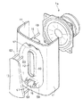
図1が本発明の一実施の形態に係るスピーカボックスの全体の外観形状を示している。このスピーカボックス10はハイインパクトポリスチレン樹脂の通常の射出成形体から構成されており、その前面側が開口になっている。そしてこの開口を塞ぐようにスピーカボックス10はフロントパネル11と組合わされるようになっている。フロントパネル11の表面であってその中間位置よりもやや下方位置には、図2および図3に示すように縦長の開口12から成る放音口が形成されるとともに、この開口12を覆うようにフロントパネル11にカバー13が結合されるようになっている。カバー13は合成樹脂、例えばハイインパクトポリスチレンの射出成形体によって一体に成形されたほぼ板状の形状をなす部材で、取手を兼用するようになっている。
【0011】
上記カバー13によって覆われる開口12の内側において、フロントパネル11には図2、図3、図5および図6に示すようにスピーカ14が取付けられるようになっている。そしてこのようなスピーカ14の上下にそれぞれ位置するようにダクト15、16がフロントパネル11の内側に突設されるようになっている。これらのダクト15、16はそれぞれ低域側の再生音を放出するためのものである。
【0012】
開口12によって形成される放音口はフロントパネル11に形成されている凹部59内に設けられており、しかもこの開口12の周縁部にはリブ60が形成され、縦長の放音口12が形成されるようになっている。そして凹部59の上下の部分には図5および図6に示すように、それぞれ取付け座61が形成されるとともに、これらの取付け座61の部分には上記カバー13の上下の端部が固定されるようになっている。なお放音口12のリブ60の前端部とカバー13の内表面との間には隙間が形成され、この隙間を通してスピーカ14の再生音が凹部59から前方に放音される。
【0013】
上下の取付け座61にはそれぞれ左右一対ずつの脚部挿通孔62が形成されるとともに、これらの脚部挿通孔62には、上記カバー13の内側であってその上下の部分にそれぞれ形成されている左右一対ずつの脚部63が挿通されるようになっている。このような脚部63は脚部挿通孔62を挿通した状態において、図6に示すようにフロントパネル11の内側から固定用ビス64によってダクト15、16の両側の部分に固定されるようになっている。
【0014】
上記フロントパネル11の内側であって放音口を構成する縦長の開口12の周囲の部分には図6および図7に示すようにリング状リブ66が形成されている。そしてこのようなリブ66に当接するように、スピーカ14が取付けられている。すなわちこのフロントパネル11のリング状リブ66の部分がスピーカ14の取付け座を構成しており、フロントパネル11がスピーカ14の取付け板を兼用するようになっている。
【0015】
フロントパネル11の上端側には図1および図2に示すように、傾斜面から成るコントロールパネル面18が形成されており、このようなコントロールパネル面18はに調整つまみ19、20、切換えつまみ21、押釦22等がそれぞれ設けられている。
【0016】
これらの調整つまみ19、20および切換えつまみ21、押釦22によって調整されるボリューム25やスイッチ等の可変素子が、このフロントパネル11のコントロールパネル面18の内側において該コントロールパネル面18と直角をなすように斜めに配されているプリント基板26の前端部にマウントされている。そしてこのプリント基板26と連結されるように別のプリント基板27が水平に配されている。これらのプリント基板26、27上にはそれぞれ電子部品28がマウントされ、ブラケット29および円柱状ボス30を介してプリント基板26、27の接合部がフロントパネル11によって支持されるようになっている。なお水平に配されているプリント基板27の後端部は保持爪31を介してスピーカボックス10の背面側の部分に支持されている。プリント基板27の下面には電子部品28とともにヒートシンク32がマウントされるようになっている。
【0017】
スピーカボックス10の背面側であってその上部側の部分には開口34、35がそれぞれ形成されている。これらの開口34、35はスピーカボックス10の内部空間の上側の部分の換気を図るようにし、あるいはまた外部の装置との接続のためのジャックを挿入するためのものである。そしてこのような開口34、35を備えるスピーカボックス10の上側の空間は仕切り板36によってスピーカ14が収納されている下側の空間と区画されるようになっている。仕切り板36は図3に示すように、この内部を横切るように設けられている。そしてこの仕切り板36の前端側の両側の部分がそれぞれフロントパネル11の両側に形成されているガイドリブ37によって挟着保持されるようになっている。
【0018】
スピーカボックス10の仕切り板36の下側の空間には上述の如くスピーカ14が収納されるようになっている。またこのスピーカ14の背面側であってスピーカボックス10の背面部の内側には図2に示すようにマウント座40が設けられており、このマウント座40にトランス41がマウントされている。
【0019】
次にこのようなスピーカボックス10の制振構造について説明する。図2および図3に示すように、スピーカボックス10内には、背面側から前方へ突出するように、仕切り板36の上側に左右一対の円筒状ボス45が突設されている。また仕切り板36の下側には、上下2段に左右一対ずつ合計4本の円筒状ボス46がマウントされるようになっている。上側の円筒状ボス45は図2に示すようにフロントパネル11の内側に突設されている円柱状ボス44と結合されるようになっている。これに対して仕切り板36の下側の4本の円筒状ボス46は制振部材47およびフロントパネル11の内側に突設されている円柱状ボス49と結合されるようになっている。
【0020】
図4および図5に示すように制振部材47はこのスピーカボックス10の内部空間を横方向に横切るように配されている。そしてこの制振部材47に設けられている一対の保持筒48によって円筒状ボス46の先端部を受入れるようにしている。保持筒48の先端部はフロントパネル11の内側に突設されている円柱状ボス49と当接されるようになっている。そして円筒状ボス46の背面側から内部を通して挿入されるビス51をこの円筒状ボス46の前端側のビス挿通孔50を挿通させ、先端部を円柱状ボス49にねじ込むことによって、円筒状ボス46と制振部材47の保持筒48と、そして円柱状ボス49とが互いに結合されるようにしている。なお円筒状ボス46はとくに図4に示すように、リブ52によってその側面であって根元側の部分が左右の側板部55に一体に連結されるようになっている。
【0021】
上記制振部材47はその長さ方向の両端がこのスピーカボックス10の左右の側板部55と当接するようになっている。しかも制振部材47の左右の端部と側板部55との間には不織布から成る緩衝材54が介在されるようになっており、このような緩衝材54を介して制振部材47が両側の側板部55を外側に押し広げるように押圧している。このような制振部材47の制振作用によって側板部55の振動に伴う箱鳴りをより確実に防止するようにしている。
【0022】
以上のような構成において、スピーカボックス10内に収納されるとともに、フロントパネル11に取付け固定されているスピーカ14のボイスコイルに駆動電流を流すと、ボイスコイルの軸線方向の振動によって振動板が振動し、再生音が縦長の開口から成る放音口12を通して前方に放出される。また低域側の再生音は上下のダクト15、16を通して放出されることになる。
【0023】
このようなスピーカ装置によれば、とくにフロントパネル11の放音口12の外側からこの放音口12を覆うようにカバー13が取付けられているために、開口12をグリル等によって覆う必要がなく、このためにグリルを必要としなくなる。そしてハイインパクトポリスチレン等の合成樹脂成形体から成るカバー13に一体に形成されている脚部63を脚部挿通孔62内に挿通させ、内側から固定用ビス64で固定するだけでカバー13が取付け固定されるために、放音口12を覆うカバー13の構造を簡潔にすることが可能になる。またこのようなカバー13によって放音口12の穴が外部に露出することがなくなる。また異物等に接触しても、カバー13によって異物がスピーカ14の振動板に接触することがなく、スピーカ14を安全に保護できるようになる。
【0024】
またこのような放音口12はその周囲にリブ60が形成されるとともに、この放音口12を覆うようにカバー13が装着されるようになっているために、このような放音口12および放音口12を形成した凹部59の形状やリブ60の高さ、あるいはまたカバー13の形状やその配置の位置等によって音の広がりを調整することが可能になり、従来のグリルを装着した放音口に比べて音の広がりの調整が容易に行ない得るようになる。
【0025】
またカバー13と放音口12のリブ60の前端との間に隙間が形成されており、凹部59によってカバー13の内側に手を挿入し、カバー13を取手としてスピーカボックス10を保持できるようになる。よって取扱いおよび持運びが便利なスピーカ装置を提供することが可能になる。
【発明の効果】
以上のように本願の主要な発明は、スピーカボックス内にスピーカを収納して成るスピーカ装置において、スピーカの取付け板を兼用する前記スピーカボックスのフロントパネルと、フロントパネルに形成されている放音口と、フロントパネルに設けられているダクトと、放音口とダクトの前面側の開口を覆うように取付けられているカバーと、を具備し、カバーは放音口よりも大きく形成され、放音口に隣接して配されるダクトの前面側の開口の前方に延出され、カバーの側端とフロントパネルとの間に放音用の隙間が形成され、しかもカバーがスピーカボックスの取手を兼用するようにしたものである。
【0026】
従ってカバーによって放音口を外側から覆うことが可能になり、放音口にグリルを装着する必要がなくなる。またカバーがスピーカボックスの取手を兼用するようになっているために、カバーを兼ねる取手によってスピーカボックスを容易に持運ぶことができ、取扱いが容易なスピーカボックスを有するスピーカ装置が提供される。
【0027】
フロントパネルを合成樹脂によって一体に成形されている成形体から構成するとともに、この成形体に形成されている縦長の開口によって放音口を構成すると、構造が簡潔で組立てが容易なスピーカボックスを備えるスピーカ装置を提供することが可能になる。
【0029】
カバーが放音口の長さ方向の端部側にそれぞれ一対の脚部を備え、該脚部がフロントパネルのダクトの前面側の開口の両側の脚部挿通孔に挿通され、内側から止着手段によって止着されるようにした構成によれば、カバーがフロントパネル上に容易かつ確実に取付けられるようになる。
【図面の簡単な説明】
【図1】本発明の一実施の形態に係るスピーカ装置の外観斜視図である。
【図2】同スピーカ装置の縦断面図である。
【図3】別の角度から見たスピーカ装置の縦断面図である。
【図4】スピーカ装置の横断面図である。
【図5】フロントパネルの構造を示す要部分解斜視図である。
【図6】同要部縦断面図である。
【図7】同要部横断面図である。
【符号の説明】
10 スピーカボックス
11 フロントパネル
12 開口(放音口)
13 カバー
14 スピーカ
15 ダクト(上)
16 ダクト(下)
18 コントロールパネル面(傾斜面)
19、20 調整つまみ
21 切換えつまみ
22 押釦
25 ボリューム
26、27 プリント基板
28 電子部品
29 ブラケット
30 円柱状ボス
31 保持爪
32 ヒートシンク
34、35 開口
36 仕切り板
37 ガイドリブ
40 マウント座
41 トランス
44 円柱状ボス
45、46 円筒状ボス
47 制振部材
48 保持筒
49 円柱状ボス
50 ビス挿通孔
51 ビス
52 リブ
54 緩衝材(不織布)
55 側板部
59 凹部
60 リブ
61 取付け座
62 脚部挿通孔
63 脚部
64 固定用ビス
66 リング状リブ[0001]
BACKGROUND OF THE INVENTION
The present invention relates to a speaker device, and more particularly to a speaker device in which a speaker is housed in a speaker box.
[0002]
[Prior art]
In general, a speaker device is configured such that a speaker body composed of dynamic speakers is housed in a speaker box. In this case, the speaker is attached to the inside of the front plate so that the diaphragm on the front side of the speaker faces the opening formed in the front plate of the speaker box. The grill is attached so as to cover the opening constituting the sound emission opening of the front plate.
[0003]
[Problems to be solved by the invention]
According to such a conventional configuration, the grill must be attached so as to cover the opening of the front plate of the speaker, and the grill is attached to the outside of the front plate via the fixing means. Since such a grill is relatively weak against external force, foreign matter or the like may break the grill and come into contact with the diaphragm of the speaker, possibly damaging the speaker. Also, the conventional grill cannot adjust the sound spread arbitrarily.
[0004]
The present invention has been made in view of such a problem, and does not require mounting a grille so as to cover the sound emission port, and has a speaker box that can safely protect the speaker. The object is to provide an apparatus.
[0005]
[Means for Solving the Problems]
Main invention of this cancer, in the speaker device formed by housing the speakers in the speaker box,
A front panel of the loudspeaker box also serves as a mounting plate of the speaker,
A sound emitting port is formed in the front panel,
A duct provided in the front panel;
A cover attached so as to cover the sound outlet and the opening on the front side of the duct ;
The cover is formed to be larger than the sound emission port, and extends in front of an opening on the front side of the duct arranged adjacent to the sound emission port, and the side end of the cover and the front the gap for sound is formed between the panels, yet in which the cover is double as the handle of the speaker box.
[0007]
The front panel may be formed of a molded body that is integrally formed of a synthetic tree, and the sound emission port may be configured by a vertically long opening formed in the molded body.
[0008]
The cover is provided with a pair of leg portions on the end side in the length direction of the sound emission port, and the leg portions are inserted into leg insertion holes on both sides of the front side opening of the duct of the front panel, It may be fastened by fastening means from the inside .
[0010]
DETAILED DESCRIPTION OF THE INVENTION
FIG. 1 shows the overall appearance of a speaker box according to an embodiment of the present invention. The
[0011]
Inside the
[0012]
The sound emission opening formed by the
[0013]
A pair of left and right
[0014]
A ring-
[0015]
As shown in FIGS. 1 and 2, a
[0016]
Variable elements such as a
[0017]
[0018]
The
[0019]
Next, the vibration damping structure of the
[0020]
As shown in FIGS. 4 and 5, the damping
[0021]
The
[0022]
In the configuration as described above, when a drive current is passed through the voice coil of the
[0023]
According to such a speaker device, since the
[0024]
In addition, since the
[0025]
Further, a gap is formed between the
【The invention's effect】
Sound or main invention of this gun is as described above, in the speaker device formed by housing the speakers in the speaker box, which is formed with the front panel of the loudspeaker box also serves as a mounting plate of the speaker, the front panel An opening, a duct provided in the front panel, and a cover that is attached to cover the sound emission opening and the opening on the front side of the duct . The cover is formed larger than the sound emission opening, and It extends in front of the opening on the front side of the duct arranged adjacent to the sound outlet, and a gap for sound emission is formed between the side edge of the cover and the front panel, and the cover serves as a handle for the speaker box. It is intended to be used for both purposes.
[0026]
Therefore, the sound outlet can be covered from the outside by the cover, and it is not necessary to attach a grill to the sound outlet. Since the cover also serves as a handle for the speaker box, the speaker box can be easily carried by the handle also serving as the cover, and a speaker device having a speaker box that is easy to handle is provided.
[0027]
When the front panel is composed of a molded body integrally formed of synthetic resin, and a sound emission port is configured by a vertically long opening formed in the molded body, a speaker box having a simple structure and easy assembly is provided. A speaker device can be provided.
[0029]
The cover has a pair of legs on the end side in the length direction of the sound outlet, and the legs are inserted into the leg insertion holes on both sides of the opening on the front side of the duct of the front panel and fixed from the inside. According to the configuration to be fastened by means cover ing to be mounted easily and reliably on the front panel.
[Brief description of the drawings]
FIG. 1 is an external perspective view of a speaker device according to an embodiment of the present invention.
FIG. 2 is a longitudinal sectional view of the speaker device.
FIG. 3 is a longitudinal sectional view of the speaker device viewed from another angle.
FIG. 4 is a cross-sectional view of the speaker device.
FIG. 5 is an exploded perspective view of the main part showing the structure of the front panel.
FIG. 6 is a longitudinal sectional view of the main part.
FIG. 7 is a cross-sectional view of the relevant part.
[Explanation of symbols]
10
13
16 Duct (bottom)
18 Control panel surface (inclined surface)
19, 20
55
Claims (3)
前記スピーカの取付け板を兼用する前記スピーカボックスのフロントパネルと、
前記フロントパネルに形成されている放音口と、
前記フロントパネルに設けられているダクトと、
前記放音口と前記ダクトの前面側の開口を覆うように取付けられているカバーと、
を具備し、前記カバーは前記放音口よりも大きく形成され、前記放音口に隣接して配される前記ダクトの前面側の開口の前方に延出され、前記カバーの側端と前記フロントパネルとの間に放音用の隙間が形成され、しかも前記カバーが前記スピーカボックスの取手を兼用することを特徴とするスピーカ装置。In a speaker device comprising a speaker housed in a speaker box,
A front panel of the speaker box that also serves as a mounting plate for the speaker;
A sound outlet formed in the front panel;
A duct provided in the front panel;
A cover attached so as to cover the sound outlet and the opening on the front side of the duct ;
The cover is formed to be larger than the sound emission port, and extends in front of an opening on the front side of the duct arranged adjacent to the sound emission port, and the side end of the cover and the front A speaker device characterized in that a sound emitting gap is formed between the panel and the cover also serves as a handle of the speaker box.
Priority Applications (1)
| Application Number | Priority Date | Filing Date | Title |
|---|---|---|---|
| JP24668995A JP3832514B2 (en) | 1995-08-31 | 1995-08-31 | Speaker device |
Applications Claiming Priority (1)
| Application Number | Priority Date | Filing Date | Title |
|---|---|---|---|
| JP24668995A JP3832514B2 (en) | 1995-08-31 | 1995-08-31 | Speaker device |
Publications (2)
| Publication Number | Publication Date |
|---|---|
| JPH0970088A JPH0970088A (en) | 1997-03-11 |
| JP3832514B2 true JP3832514B2 (en) | 2006-10-11 |
Family
ID=17152170
Family Applications (1)
| Application Number | Title | Priority Date | Filing Date |
|---|---|---|---|
| JP24668995A Expired - Fee Related JP3832514B2 (en) | 1995-08-31 | 1995-08-31 | Speaker device |
Country Status (1)
| Country | Link |
|---|---|
| JP (1) | JP3832514B2 (en) |
Families Citing this family (5)
| Publication number | Priority date | Publication date | Assignee | Title |
|---|---|---|---|---|
| JP4691287B2 (en) * | 2001-09-27 | 2011-06-01 | 株式会社ニューギン | Game machine |
| JP4691288B2 (en) * | 2001-09-27 | 2011-06-01 | 株式会社ニューギン | Game machine |
| JP5499911B2 (en) * | 2010-06-01 | 2014-05-21 | アンデン株式会社 | Vehicle alarm |
| JP5712965B2 (en) * | 2011-06-22 | 2015-05-07 | アンデン株式会社 | Vehicle sound generator |
| CN103096193A (en) * | 2013-01-16 | 2013-05-08 | 刘骏涛 | Voice box |
-
1995
- 1995-08-31 JP JP24668995A patent/JP3832514B2/en not_active Expired - Fee Related
Also Published As
| Publication number | Publication date |
|---|---|
| JPH0970088A (en) | 1997-03-11 |
Similar Documents
| Publication | Publication Date | Title |
|---|---|---|
| KR100882303B1 (en) | Speaker device | |
| JP3832514B2 (en) | Speaker device | |
| JP3063297U (en) | Speaker mounting structure | |
| JPH1066179A (en) | Speaker-attaching facility | |
| JP3674641B2 (en) | Speaker box | |
| JP2541017B2 (en) | Electronic musical instrument speaker box | |
| JP2001145186A (en) | Television receiver | |
| JP4487797B2 (en) | Arrangement structure of speaker device in bathroom | |
| KR20000004269A (en) | Apparatus for preventing a vibration of a television speaker | |
| JP3737109B2 (en) | Apparatus having speaker unit, speaker unit and speaker housing | |
| US4177873A (en) | Loudspeaker equipment | |
| KR100287431B1 (en) | Framed Speaker | |
| KR960006261Y1 (en) | Speaker apparatus for middle and low tone of tv set | |
| JP2001268478A (en) | Television stand with built-in speaker | |
| JP3318191B2 (en) | Parts holder | |
| KR200319127Y1 (en) | A speaker device for televisions | |
| KR200374905Y1 (en) | Horn Type Tweeter Speaker | |
| JP3059695U (en) | Speaker mounting structure | |
| KR100374362B1 (en) | Small built-in speaker system | |
| KR200146719Y1 (en) | Anti-vibration unit of speaker | |
| KR0117238Y1 (en) | Equalizer device for a guitar | |
| KR100238988B1 (en) | speaker of automobile | |
| JPS6336774Y2 (en) | ||
| KR19990041565U (en) | Stereo TV speakers | |
| JP2005057718A (en) | Speaker device |
Legal Events
| Date | Code | Title | Description |
|---|---|---|---|
| A977 | Report on retrieval |
Free format text: JAPANESE INTERMEDIATE CODE: A971007 Effective date: 20040927 |
|
| A131 | Notification of reasons for refusal |
Free format text: JAPANESE INTERMEDIATE CODE: A131 Effective date: 20040929 |
|
| A521 | Written amendment |
Free format text: JAPANESE INTERMEDIATE CODE: A523 Effective date: 20041122 |
|
| A131 | Notification of reasons for refusal |
Free format text: JAPANESE INTERMEDIATE CODE: A131 Effective date: 20051102 |
|
| A521 | Written amendment |
Free format text: JAPANESE INTERMEDIATE CODE: A523 Effective date: 20060104 |
|
| TRDD | Decision of grant or rejection written | ||
| A01 | Written decision to grant a patent or to grant a registration (utility model) |
Free format text: JAPANESE INTERMEDIATE CODE: A01 Effective date: 20060628 |
|
| A61 | First payment of annual fees (during grant procedure) |
Free format text: JAPANESE INTERMEDIATE CODE: A61 Effective date: 20060711 |
|
| LAPS | Cancellation because of no payment of annual fees |