JP3831924B2 - Capsule type latent heat storage system - Google Patents
Capsule type latent heat storage system Download PDFInfo
- Publication number
- JP3831924B2 JP3831924B2 JP2003208240A JP2003208240A JP3831924B2 JP 3831924 B2 JP3831924 B2 JP 3831924B2 JP 2003208240 A JP2003208240 A JP 2003208240A JP 2003208240 A JP2003208240 A JP 2003208240A JP 3831924 B2 JP3831924 B2 JP 3831924B2
- Authority
- JP
- Japan
- Prior art keywords
- heat
- heat storage
- storage tank
- load
- transfer fluid
- Prior art date
- Legal status (The legal status is an assumption and is not a legal conclusion. Google has not performed a legal analysis and makes no representation as to the accuracy of the status listed.)
- Expired - Fee Related
Links
Images


Description
【0001】
【発明の属する技術分野】
本発明は、例えば建屋内を冷、暖房する空調システムや冷却、加熱を必要とするプロセスに適用し、電気料金の割安な夜間電力で熱源機を運転して蓄熱し、昼間の時間帯に放熱するカプセル式潜熱蓄熱システムに関する。
【0002】
【従来の技術】
従来の熱源設備としての夜間負荷対応システムでは、図10(A)に示すように熱源機320、蓄熱槽301及び冷熱使用機器326側と熱交換する熱交換器328等をそれぞれバイパス管を介して循環管路325、327に直列に配置した夜間蓄熱ラインとは別に、図10(B)に示す夜間負荷対応専用ラインとして、夜間負荷に対応するための専用の熱源機322、ポンプP302、配管系326等を必要としており、このため変動負荷に対しては熱源機のON、OFF、あるいは容量制御動作で対応せざるを得ないことから熱源機のCOP(成績係数)が低い不安定な運転となり、ランニングコストが増加する部分負荷運転で対応していた。
【0003】
また、蓄熱運転時における熱の一部を、夜間負荷に対応させることは従来から実施されているが、夜間負荷が昼間の負荷に比べて小さいことが多く、このため昼間の通常運転用の配管では口径が大き過ぎて温度計測が不安定になるなどの理由で、図11に示すように昼間の通常放熱運転用配管および放熱用熱交換器とは別に専用の小口径の配管及び制御弁V5’,V6’を含む制御系と夜間負荷対応専用の熱交換器28’などを設置せざるを得なかった。
【0004】
この種の、従来の熱源設備として直膨式蓄熱槽、すなわちフロン冷媒をコイルチューブ等に流すことにより、コイルチューブ等の外回りにある蓄熱材と熱交換する蓄熱槽(特許文献1参照)や、フロン回路に2種類の膨張弁を設けて製氷用と冷房用の2種類の温度を作り出すもの(特許文献2参照)が提案されている。
【0005】
【特許文献1】
特開平9−152225号公報(段落0056、段落0066
図1)
【特許文献2】
特開2001−330279号公報(段落0031、図7)
【0006】
【発明が解決しようとする課題】
そこで、本発明者等は、例えば氷蓄熱の夜間時における製氷運転温度(例えば−5℃)と昼間の空調温度(例えば+5℃)の両者の温度差に着目し鋭意研究の結果、夜間の製氷温度(例えば−5℃)は製氷に用いられた後も冷房空調用として使用するのに十分低い温度(例えば−2℃)が保たれていることを見出し、本発明を完成させた。
【0007】
従って、本発明の目的とするところは、夜間の蓄熱運転時に於ける熱エネルギーをそのまま熱負荷対応運転に適用することにより、蓄熱・熱負荷対応同時運転を達成することができるカプセル式潜熱蓄熱システムを提供することである。
また、本発明のもう一つの目的は、夜間負荷対応専用の配管や熱源機及び熱交換器等の設置を不要とし、通常放熱運転時における配管および熱源機及び熱交換器等の兼用を可能とすることで設備の簡素化を図ることができるカプセル式潜熱蓄熱システムを提供することである。
【0008】
【課題を解決する為の手段】
上記目的を達成するために、本発明は次の技術的手段を有する。即ち、実施の形態に対応する添付図面に使用した符号を用いて説明すると、熱源機20、蓄熱槽1、熱交換器28、及び該各機器を結んで配管した伝熱流体循環管路25a,25b,25cを備え、蓄熱運転として上記熱源機20と蓄熱槽1との間で伝熱流体を循環して熱源機20の生成熱を蓄熱槽1に蓄熱し、放熱運転として上記蓄熱槽1と熱交換器28との間で伝熱流体を循環して蓄熱槽1に貯えた熱量を上記熱交換器28に放熱付与するカプセル式潜熱蓄熱システムに於いて、熱源機20を出た伝熱流体を循環管路25a,25b,25cを介して蓄熱槽1に通して蓄熱し、該蓄熱槽1を出た伝熱流体を、夜間の熱負荷に対応するようその一部または全量を制御された流量として熱使用機器26側の熱交換器28に導き、該熱交換器28入口側の制御弁V5あるいは該熱交換器28の上、下流の間に接続されたバイパス管の制御弁V6を通した伝熱流体を循環管路25cを介して再び蓄熱槽1に戻るように構成し、蓄熱動作をするための夜間の蓄熱運転時には、上記制御弁V5を全閉とすると共に上記制御弁V6を全開とし、夜間の熱負荷対応時には制御弁V5及びV6の開度を上記熱負荷に応じて制御することで蓄熱・熱負荷対応同時運転を行なうようにしたことを特徴とするカプセル式潜熱蓄熱システムである。
従って、夜間の熱負荷対応時には制御弁V5およびV6の開度を上記熱負荷に応じて制御し、蓄熱・熱負荷対応同時運転を行なうようにすることで、夜間の熱負荷対応専用の熱源システムの設置が不要となる。
【0009】
また本発明は、上記蓄熱槽1の出口側と上記熱使用機器26側の熱交換器28の入口間に接続された循環管路25bの途中に、該循環管路25bの管径より小径の伝熱管24aを平行に接続し、夜間の熱負荷対応時には上記伝熱流体を小径伝熱管24aに切替え小径伝熱管24aでの伝熱流体温度を適切に制御するようにした潜熱利用蓄熱装置である。
従って、通常放熱運転時における配管および熱交換器28を夜間の熱負荷対応運転時との兼用を可能とすることで設備の簡素化を図ることができる。
【0010】
【発明の実施の形態】
以下、本発明の実施形態を添付図面に基づき詳細に説明する。
【0011】
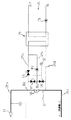
図1〜図5は本発明のカプセル式潜熱蓄熱システムに係る第1実施形態を示しており、図1は本発明の夜間の蓄熱運転時において夜間の熱負荷に対応する蓄熱・熱負荷対応同時運転時における説明図、図2は蓄熱槽の放熱ピーク時に熱源機を併用運転している放熱運転時の説明図、図3は蓄熱槽単独運転における放熱運転時の説明図、図4は熱源機単独運転における熱負荷対応運転時の説明図、図5は夜間の蓄熱運転時、夜間負荷がない場合における説明図である。
【0012】
最初に熱使用機器として、冷房,冷凍装置に適用した例に付き図9を参照して説明する。
【0013】
図9の(A)〜(C)における符号1は、本発明のカプセル式蓄熱槽であって、このカプセル式蓄熱槽1(以下蓄熱槽1と称する)は、円筒形あるいは矩形の胴体2と、円筒形の場合では上下あるいは左右両端に取着された胴体蓋4,5とを有している。
【0014】
円筒形の場合では、上下あるいは左右両端の胴体蓋4,5中央には夫々上下の接続口6,8が設けられており、これら上下の接続口6,8には図示しない伝熱管が接続されている。上記胴体蓋4,5の内部には、上下の接続口6,8に対向して配設された伝熱媒体の分散器10,12が設置されており、これら分散器10,12には、胴体内部16に伝熱媒体を拡散流通させる多数の小孔が形成されている。
【0015】
上記分散器10,12によって仕切られる胴体2の内部には、周知の小球状蓄熱体18(例えば特公平5−81832号公報)が多数、密に充填されており、これら小球状蓄熱体18は、相変化温度で液相から固相に変わる時に固化の潜熱として冷熱を蓄熱し、固相から液相に相変化する時に先に蓄熱した冷熱を放出する蓄熱材を球状のシェル内に封入したものであり、好適な蓄熱材としては、例えば、H2O(水)に発核剤を微量添加した組成物を主液としている。
【0016】
勿論、温熱を対象とする場合には、小球状蓄熱体18内に封入された蓄熱媒材は、相変化温度で融解した時に蓄熱し、凝固した時に凝固潜熱を放出する。
【0017】
次に、図1〜図5に従い本発明の好適な第1実施形態に付き詳述する。
【0018】
先ず、図1〜図5に示される共通の装置に付き説明する。以下に説明する全図において、開閉弁のバルブ記号は黒塗りが閉弁状態、白塗りが開弁状態、片側黒塗り、片側白塗りが開度調節(制御)状態を示している。図1〜図5に示す20は冷熱源機であって、22は冷熱を発生する冷凍機などの冷凍装置を示し、28は冷熱使用機器26側の熱交換器である。
【0019】
図1に示すように、循環管路25cと25a間には、冷熱源機20側の冷凍装置22が接続されると共に、開閉弁V1を備えたバイパス管が接続されている。また、循環管路25aと25b間には、蓄熱槽1が接続されると共に制御弁V3を備えたバイパス管が接続されている。そして、蓄熱槽1と制御弁V3を備えたバイパス管の合流点B1の下流側には、ブラインポンプP1が接続されている。
【0020】
ブラインポンプP1に接続された循環管路25bの下流には、冷熱使用機器26側の熱交換器28に接続されていて、この熱交換器28の上流と下流の間にはバイパス管27が接続されている。
【0021】
冷熱使用機器26は、例えば冷房装置などの空調機であって、この空調機は、熱交換器28で冷やされた伝熱流体をポンプP3によってIN側からOUT側に循環させる過程で放冷されるようになっている。
【0022】
また、熱負荷対応時冷熱使用機器26は、使用機器側の伝熱流体の温度を検知する温度センサ30の検知温度によって流量を制御するため、熱交換器28の入口側には制御弁V5が、バイパス管27には制御弁V6がそれぞれ接続されており、熱交換器28の出口に接続された循環管路25cは冷凍装置22に接続されている。
【0023】
次に、上記のように構成された第1実施形態に係る一連の動作に付き図1を参照して説明する。
【0024】
図1に示す夜間の冷熱蓄熱運転時における夜間の熱負荷に対応する蓄熱・熱負荷対応同時運転時では、開閉弁V1の閉塞によって、冷熱源機20の冷凍装置22から循環管路25aに出た伝熱媒体は、図中太線で示す管路を移動する。
【0025】
冷熱蓄熱運転時間は、例えば、午後の10時から翌朝8時までの10時間運転であって、蓄熱・熱負荷対応同時運転時に於いては、冷熱源機20の冷凍装置22から出た低温の伝熱媒体は、図中太線で示すように循環管路25a下流の制御弁V3の閉鎖により、制御弁V4を介して蓄熱槽1に通して蓄熱し、この蓄熱槽1を出た伝熱媒体は、ブラインポンプP1上流側の分岐点B1に至る。
【0026】
ここで標準時における冷凍装置22の入口温度約−2℃に対し、出口温度は約−5℃であり、蓄熱完了時における冷凍装置22の入口温度約−4℃に対し、出口温度は−5〜−7℃となる。
【0027】
循環管路25a下流側の分岐点B1に合流した低温の伝熱媒体は、ブラインポンプP1の起動により循環管路25bから制御弁V5を介して熱交換器28を通過して放熱すると共に、バイパス管27の制御弁V6を通過した伝熱媒体と共に循環管路25cから再び冷凍装置22に戻る。
【0028】
従って、夜間の冷熱蓄熱運転時における夜間の熱負荷に対応する蓄熱・熱負荷対応同時運転時においては、夜間の冷熱負荷対応時には制御弁V5およびV6の開度を熱負荷である温度センサ30の検知温度に応じて制御し、蓄熱・熱負荷対応同時運転を行なうようにすることで、夜間負荷対応専用の配管や熱源機及び熱交換器等の設置を不要とすることができる。
【0029】
次に、図5に示す夜間の冷熱蓄熱運転時では、図1と同様に冷熱源機20の冷凍装置22から循環管路25aに出た伝熱媒体は、図中太線で示す管路を移動する。
【0030】
ここで、同じ管路は同じ符号を付して重複する説明を省略するが、ブラインポンプP1を出た伝熱媒体は、制御弁V5を閉じることで冷熱使用機器26側の制御弁V6を介してバイパス管27を通り、循環管路25cから再び冷凍装置22に戻る。
【0031】
従って、上記のように夜間の冷熱蓄熱運転時では、通常放熱運転時における循環管路25bおよび熱交換器28を夜間の冷熱負荷対応運転時との兼用を可能とすることで設備の簡素化を図ることができる。
【0032】
次に図2は、熱負荷のピーク期に蓄熱槽と冷凍機を併用運転している放熱運転を示している。この場合の放熱運転時間は、例えば、朝の8時から22時までの14時間運転であって、冷熱源機20の冷凍装置22を出た伝熱媒体は、図中太線で示す管路を移動する。
【0033】
ここで、ピーク期における冷凍装置22の入口温度約13℃に対し出口温度は8℃で蓄熱槽1の出口温度は4℃に設定される。
【0034】
開閉弁V1の閉塞によって、冷熱源機20の冷凍装置22から循環管路25aに出た伝熱媒体は、温度センサー31の検知温度に応じて制御される制御弁V3およびV4を分流通過し、合流点B1に至る。
【0035】
循環管路25a下流の分岐点B1に合流した伝熱媒体は、ブラインポンプP1の起動により循環管路25bから制御弁V5を介して熱交換器28を通過して放熱すると共に、バイパス管27の制御弁V6を通過した伝熱媒体と共に循環管路25cから再び冷凍装置22に戻る。
【0036】
次に図3は、蓄熱槽単独運転における放熱運転を示している。この蓄熱槽1の単独運転は、例えば、昼間の午後13時から午後の16時迄の3時間運転であって、蓄熱槽1を出た伝熱媒体は、図中太線で示す管路を移動する。ここで、蓄熱槽1の入口温度が約13℃に対し出口温度が4℃に設定される。
【0037】
蓄熱槽1を出た伝熱媒体は、分岐点B1で蓄熱槽1をバイパスした伝熱媒体と合流したのち、ブラインポンプP1の起動により循環管路25bから制御弁V5を介して熱交換器28を通過して放熱すると共に、バイパス管27の制御弁V6を通過した伝熱媒体と共に循環管路25cから冷熱源機20、及びバイパスの開閉弁V1を通過し、再び蓄熱槽1に戻る。
【0038】
次に図4は冷凍装置単独運転における冷房運転を示している。この冷凍装置の単独運転は、例えば、非常時または昼間、夜間時に運転され、開閉弁V1の閉塞によって、冷熱源機20の冷凍装置22から循環管路25aに出た伝熱媒体は、図中太線で示す管路を移動する。
【0039】
冷熱源機20の冷凍装置22から循環管路25aに出た低温の伝熱媒体は、図中太線で示すように制御弁V3、分岐点B1を介してブラインポンプP1の起動により循環管路25bから制御弁V5を介して熱交換器28を通過して放熱すると共に、バイパス管27の制御弁V6を通過した伝熱媒体と共に循環管路25cから再び冷凍装置22に戻る。
【0040】
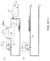
次に、図6〜図8は本発明のカプセル式潜熱蓄熱システムに係る第2実施形態を示しており、図6は本発明の夜間の蓄熱運転時において夜間の熱負荷に対応するため蓄熱・熱負荷対応同時運転とし、且つ熱交換器への供給温度を小径管部にて制御する場合の説明図、図7は昼間の冷房あるいは放熱運転時の小径配管部回りの説明図であり、図8は夜間負荷がない場合の夜間蓄熱運転時の小径配管部回りの説明図である。
【0041】
先ず、夜間の熱負荷対応時における冷熱負荷使用機器26側の熱交換器28への供給温度は、後述する小径伝熱管24aの温度計指示値に基き、制御弁V7およびV8の開度調節によって制御されるようになっている。従って、蓄熱運転時には、ブラインポンプP1が起動し、夜間負荷対応時にはポンプP2も起動することで、蓄熱槽1出口側における冷熱の一部が夜間負荷に適用されることになる。
【0042】
すなわち、夜間の冷熱蓄熱運転時における夜間の熱負荷に対応する蓄熱・熱負荷対応同時運転では、図6に示すように蓄熱槽1から流出した伝熱流は、ブラインポンプP1によって熱交換器28側の分岐点B2に至る。伝熱流体の一部は、その分岐点B2から循環ポンプP2を介し小径配管24aを通って熱交換器28へ供給される。
【0043】
この熱交換器28で夜間負荷に供した伝熱流体は、循環管路25dを通り、バイパス管27からの伝熱流体と合流した後、循環管路25cに至り、熱源機側へ戻る。循環管路25dの伝熱流体の一部は制御弁V8側へ流れて、制御弁V7側からの伝熱流体と分岐点B3にて合流し、循環ポンプP2へ循環される。
【0044】
更に、図7に示す昼間の冷房あるいは放熱運転時における昼間の熱負荷に対応する冷房あるいは放熱運転では、図2、図3に示すように蓄熱槽1あるいは熱源機20から流出した伝熱媒体は、ブラインポンプP1によって熱交換器28側の分岐点B2に至る。
【0045】
ここで、伝熱流体の全量は、制御弁V5を介し熱交換器28で昼間に熱負荷に供した後、循環管路25d,25cを介して熱源機側へ戻るが、図7に示すA部の伝熱流体の流れとしては、図2,図3,図4で説明した熱源機・蓄熱槽併用運転時、蓄熱槽単独運転時、熱源機単独運転時のいずれの場合も同様の流れとなる。この場合は、熱負荷が夜間負荷と比較して大きいために小径配管ではなく、大径配管25bを介して運転される。
【0046】
そして、図8に示す夜間負荷がない場合の夜間蓄熱運転では、制御弁V5,V7,V8の閉止、制御弁V6の全開によって伝熱流体全量は、バイパス管27を介して循環管路25cへ至り、熱源機側へ戻ることになる。
【0047】
従って、上記の実施形態においては、この装置を冷房、冷凍装置に適用した例を示し、熱使用機器における熱交換器へ冷熱を伝える場合を示したが、本発明のカプセル式潜熱蓄熱システムは、これに限定されることなく、他の冷熱利用装置にも適用できる他、熱使用機器を太陽熱装置や、暖房熱源供給装置として、そこから熱使用機器に於ける熱交換器へ温熱を伝えるような装置にも、このカプセル式潜熱蓄熱システムを適用でき、蓄熱時には、蓄熱槽内に潜熱が蓄熱され、放熱時には熱使用機器の熱交換器へ温熱が放熱される。
【0048】
勿論、温熱を対象とする場合には、小球状蓄熱体18内に封入された蓄熱材は、相変化温度で融解した時に蓄熱し、凝固した時に凝固潜熱を放出する。
【0049】
【発明の効果】
以上詳述した如く、本発明によると次の様な効果を奏する。
【0050】
即ち、請求項1によると、夜間の熱負荷対応時には制御弁の開度を上記熱負荷に応じて制御し、蓄熱・熱負荷対応同時運転を行なうようにすることで、夜間負荷対応専用の配管や熱源機及び熱交換器等の設置が不要となる。
【0051】
また請求項2によると、夜間負荷のような小負荷に対応するための小径配管を併設することにより、安定で適切な夜間負荷供給温度制御が可能となる。このことにより、例えば、冷熱供給の場合では、氷点下温度の供給を避けることができ、即ち,熱交換器での2次側冷水のリスクの軽減が図れるなどの効果を奏する。
【図面の簡単な説明】
【図1】本発明の第1実施形態に係る夜間の蓄熱運転時において夜間の熱負荷に対応する蓄熱・熱負荷対応同時運転時における説明図である。
【図2】同じく、熱負荷のピーク期に蓄熱槽と熱源機を併用運転している放熱運転時の説明図である。
【図3】同じく、蓄熱槽単独運転における放熱運転時の説明図である。
【図4】同じく、熱源機単独運転における冷房運転時の説明図である。
【図5】同じく、夜間の蓄熱運転時、夜間負荷がない場合における説明図である。
【図6】本発明の第2実施形態に係る夜間の蓄熱運転時において夜間の熱負荷に対応するため蓄熱・熱負荷対応同時運転とし、且つ熱交換器への供給温度を小径管部にて制御する場合の説明図である。
【図7】同じく、昼間の冷房あるいは放熱運転時の小径配管部回りの説明図である。
【図8】同じく、夜間負荷がない場合の夜間蓄熱運転時の小径配管部回りの説明図である。
【図9】本発明に係るカプセル式蓄熱槽の実施例であって、(A)、(B)は円筒形胴体のカプセル式蓄熱槽の一部断面を示す側面図、(C)は矩形胴体のカプセル式蓄熱槽の斜視図である。
【図10】(A),(B)は、夜間負荷に対応するための従来の蓄熱システムの説明図である。
【図11】(A),(B)は、夜間負荷に対応するための従来の蓄熱システムの説明図である。
【符号の説明】
1 蓄熱槽(カプセル式蓄熱槽)
2 胴体
4,5 胴体蓋
6,8 接続口
10,12 分散器
16 胴体内部
18 小球状蓄熱体
20 冷熱源機
22 冷凍装置
24a 小径管路(小径伝熱管)
25a〜25d 循環管路
26 冷熱使用機器
27 バイパス管
28 熱交換器
30,31,32 温度センサ
B1,B2,B3 分岐点
P1,P2 ブラインポンプ
P3 ポンプ
V1,V2 開閉弁
V3,V4,V5 制御弁
V6,V7,V8 制御弁[0001]
BACKGROUND OF THE INVENTION
The present invention is applied to, for example, an air conditioning system that cools and heats a building or a process that requires cooling and heating, and heat is stored by operating a heat source device at night electricity with a low electricity charge, and is dissipated during daytime hours. The present invention relates to a capsule-type latent heat storage system.
[0002]
[Prior art]
In a night load system as a conventional heat source facility, as shown in FIG. 10 (A), a
[0003]
In addition, it has been practiced that some of the heat during the heat storage operation corresponds to the night load, but the night load is often smaller than the day load. Then, because the diameter is too large and the temperature measurement becomes unstable, as shown in FIG. 11, a dedicated small-diameter pipe and control valve V5 separate from the normal heat-dissipating operation pipe and heat-dissipating heat exchanger as shown in FIG. A control system including ', V6' and a heat exchanger 28 'dedicated to night loads must be installed.
[0004]
As this type of conventional heat source equipment, a direct expansion type heat storage tank, that is, a heat storage tank (see Patent Document 1) for exchanging heat with a heat storage material around the coil tube or the like by flowing a CFC refrigerant to the coil tube or the like, There has been proposed a type in which two types of expansion valves are provided in a freon circuit to produce two types of temperatures for ice making and cooling (see Patent Document 2).
[0005]
[Patent Document 1]
JP-A-9-152225 (paragraph 0056, paragraph 0066
(Fig. 1)
[Patent Document 2]
JP 2001-330279 A (paragraph 0031, FIG. 7)
[0006]
[Problems to be solved by the invention]
Therefore, the present inventors, for example, focused on the temperature difference between the ice-making operation temperature (for example, −5 ° C.) and the daytime air-conditioning temperature (for example + 5 ° C.) during ice storage, and as a result of earnest research, It was found that the temperature (for example, −5 ° C.) was sufficiently low (for example, −2 ° C.) to be used for cooling air conditioning even after being used for ice making, and the present invention was completed.
[0007]
Accordingly, an object of the present invention is to provide a capsule-type latent heat storage system capable of achieving simultaneous operation corresponding to heat storage and heat load by directly applying heat energy at the time of heat storage operation at night to operation corresponding to heat load. Is to provide.
Another object of the present invention is that it is not necessary to install pipes, heat source units, heat exchangers, etc. dedicated to night loads, and can be used as pipes, heat source units, heat exchangers, etc. during normal heat radiation operation. This is to provide a capsule-type latent heat storage system capable of simplifying equipment.
[0008]
[Means for solving the problems]
In order to achieve the above object, the present invention has the following technical means. That is, when described using the reference numerals used in the accompanying drawings corresponding to the embodiment, the
Therefore, when the nighttime heat load is supported, the opening degree of the control valves V5 and V6 is controlled according to the heat load, and the simultaneous operation corresponding to the heat storage / heat load is performed. Installation is not required.
[0009]
In the present invention, the diameter of the
Therefore, it is possible to simplify the equipment by allowing the piping and the
[0010]
DETAILED DESCRIPTION OF THE INVENTION
Embodiments of the present invention will be described below in detail with reference to the accompanying drawings.
[0011]
1 to 5 show a first embodiment of the capsule-type latent heat storage system of the present invention. FIG. 1 shows the simultaneous heat storage and heat load corresponding to the night heat load during the night heat storage operation of the present invention. 2 is an explanatory diagram at the time of heat dissipation operation, FIG. 2 is an explanatory diagram at the time of heat dissipation operation in which the heat source unit is operated together at the heat dissipation peak of the heat storage tank, FIG. FIG. 5 is an explanatory diagram at the time of the heat load operation in the single operation, and FIG. 5 is an explanatory diagram in the case of no night load at the night heat storage operation.
[0012]
First, an example of application to a cooling and freezing apparatus as a heat-using device will be described with reference to FIG.
[0013]
[0014]
In the case of the cylindrical shape, upper and
[0015]
A large number of well-known small spherical heat accumulators 18 (for example, Japanese Patent Publication No. 5-81832) are closely packed in the
[0016]
Of course, when heat is the target, the heat storage medium material enclosed in the small spherical
[0017]
Next, a preferred first embodiment of the present invention will be described in detail with reference to FIGS.
[0018]
First, the common apparatus shown in FIGS. 1 to 5 will be described. In all the drawings described below, the valve symbols of the on-off valves indicate that the black paint is in the closed state, the white paint is in the open valve state, the one-side black paint, and the one-side white paint is the opening adjustment (control) state. 1 to 5,
[0019]
As shown in FIG. 1, between the
[0020]
Downstream of the
[0021]
The cold
[0022]
In addition, since the cooling /
[0023]
Next, a series of operations according to the first embodiment configured as described above will be described with reference to FIG.
[0024]
In the simultaneous heat storage / heat load correspondence operation corresponding to the nighttime heat load during the nighttime cold energy storage operation shown in FIG. 1, the on-off valve V1 closes and the refrigerant is discharged from the
[0025]
The cold heat storage operation time is, for example, a 10 hour operation from 10:00 in the afternoon to 8:00 in the next morning, and in the simultaneous operation corresponding to heat storage and heat load, the low temperature output from the
[0026]
Here, the outlet temperature is about −5 ° C. with respect to the inlet temperature of the
[0027]
The low-temperature heat transfer medium that has joined the branch point B1 downstream of the
[0028]
Accordingly, during simultaneous storage and heat load handling corresponding to the nighttime heat load during nighttime cold energy storage operation, the opening degree of the control valves V5 and V6 of the
[0029]
Next, during the nighttime cold energy storage operation shown in FIG. 5, the heat transfer medium that has flowed out of the
[0030]
Here, the same pipes are denoted by the same reference numerals, and redundant description is omitted. However, the heat transfer medium that has exited the brine pump P1 is closed via the control valve V6 on the side of the
[0031]
Therefore, during the nighttime cold heat storage operation as described above, the
[0032]
Next, FIG. 2 shows the heat radiation operation in which the heat storage tank and the refrigerator are operated in combination during the peak period of the heat load. The heat radiation operation time in this case is, for example, a 14-hour operation from 8:00 to 22:00 in the morning, and the heat transfer medium that exits the
[0033]
Here, the outlet temperature is set to 8 ° C. and the outlet temperature of the
[0034]
Due to the closure of the on-off valve V1, the heat transfer medium that has flowed from the
[0035]
The heat transfer medium that has joined the branch point B1 downstream of the
[0036]
Next, FIG. 3 shows the heat radiation operation in the heat storage tank single operation. The single operation of the
[0037]
The heat transfer medium that has exited the
[0038]
Next, FIG. 4 shows the cooling operation in the independent operation of the refrigeration apparatus. The refrigeration apparatus is operated alone, for example, in an emergency, daytime, or nighttime. The heat transfer medium that has flowed from the
[0039]
The low-temperature heat transfer medium that has flowed from the
[0040]
Next, FIGS. 6 to 8 show a second embodiment of the capsule latent heat storage system of the present invention, and FIG. 6 shows the heat storage / FIG. 7 is an explanatory diagram of the case where the simultaneous operation corresponding to the heat load is performed and the supply temperature to the heat exchanger is controlled by the small-diameter pipe portion, and FIG. 7 is an explanatory diagram around the small-diameter pipe portion during the daytime cooling or heat radiation operation. 8 is an explanatory view around the small-diameter piping section during night heat storage operation when there is no night load.
[0041]
First, the supply temperature to the
[0042]
That is, in the heat storage / heat load compatible simultaneous operation corresponding to the nighttime heat load during the cold heat storage operation at night, as shown in FIG. 6, the heat transfer flow flowing out of the
[0043]
The heat transfer fluid supplied to the night load by the
[0044]
Further, in the cooling or heat radiation operation corresponding to the daytime cooling or heat radiation operation shown in FIG. 7, the heat transfer medium flowing out from the
[0045]
Here, the total amount of the heat transfer fluid is supplied to the heat source in the daytime by the
[0046]
In the nighttime heat storage operation when there is no night load shown in FIG. 8, the total amount of the heat transfer fluid is transferred to the
[0047]
Therefore, in the above embodiment, an example in which this apparatus is applied to a cooling and refrigeration apparatus is shown, and a case where cold heat is transmitted to a heat exchanger in a heat-using device has been shown, but the capsule latent heat storage system of the present invention is It is not limited to this, but can be applied to other cold energy utilization devices, and the heat use device can be used as a solar heat device or a heating heat source supply device, from which heat is transmitted to the heat exchanger in the heat use device. This capsule-type latent heat storage system can also be applied to the apparatus. During heat storage, latent heat is stored in the heat storage tank, and during heat dissipation, heat is radiated to the heat exchanger of the heat-using device.
[0048]
Of course, when heat is the target, the heat storage material enclosed in the small spherical
[0049]
【The invention's effect】
As described in detail above, the present invention has the following effects.
[0050]
That is, according to the first aspect, when the nighttime heat load is supported, the opening degree of the control valve is controlled according to the heat load, and the simultaneous operation corresponding to the heat storage / heat load is performed. Installation of a heat source machine and a heat exchanger becomes unnecessary.
[0051]
According to
[Brief description of the drawings]
FIG. 1 is an explanatory diagram of a simultaneous heat storage / heat load corresponding operation corresponding to a night heat load during a night heat storage operation according to the first embodiment of the present invention.
FIG. 2 is also an explanatory view of a heat radiation operation in which a heat storage tank and a heat source device are operated in combination during a peak period of heat load.
FIG. 3 is also an explanatory view at the time of heat radiation operation in a single heat storage tank operation.
FIG. 4 is also an explanatory diagram at the time of cooling operation in heat source machine single operation.
FIG. 5 is also an explanatory diagram when there is no night load during a heat storage operation at night.
FIG. 6 shows simultaneous heat storage and heat load operation in order to cope with nighttime heat load during nighttime heat storage operation according to the second embodiment of the present invention, and the supply temperature to the heat exchanger is set at a small diameter pipe portion. It is explanatory drawing in the case of controlling.
FIG. 7 is also an explanatory view around a small-diameter pipe section during daytime cooling or heat radiation operation.
FIG. 8 is also an explanatory diagram around a small-diameter pipe section during night heat storage operation when there is no night load.
FIG. 9 is an embodiment of a capsule heat storage tank according to the present invention, wherein (A) and (B) are side views showing a partial cross section of the capsule heat storage tank of a cylindrical body, and (C) is a rectangular body. It is a perspective view of a capsule type heat storage tank.
FIGS. 10A and 10B are explanatory diagrams of a conventional heat storage system for dealing with night loads. FIGS.
FIGS. 11A and 11B are explanatory diagrams of a conventional heat storage system for dealing with a night load. FIGS.
[Explanation of symbols]
1 Thermal storage tank (capsule thermal storage tank)
2
25a to
Claims (2)
熱源機20を出た伝熱流体を循環管路25a,25b,25cを介して蓄熱槽1に通して蓄熱し、該蓄熱槽1を出た伝熱流体を、夜間の熱負荷に対応するようその一部または全量を制御された流量として熱使用機器26側の熱交換器28に導き、該熱交換器28入口側の制御弁V5あるいは該熱交換器28の上、下流の間に接続されたバイパス管の制御弁V6を通した伝熱流体を循環管路25cを介して再び蓄熱槽1に戻るように構成し、蓄熱動作をするための夜間の蓄熱運転時には、上記制御弁V5を全閉とすると共に上記制御弁V6を全開とし、夜間の熱負荷対応時には上記制御弁V5及びV6の開度を上記熱負荷に応じて制御することで蓄熱・熱負荷対応同時運転を行なうにしたことを特徴とするカプセル式潜熱蓄熱システム。A heat source unit 20, a heat storage tank 1, a heat exchanger 28, and heat transfer fluid circulation pipes 25a, 25b, and 25c that connect and connect the devices are provided between the heat source unit 20 and the heat storage tank 1 as a heat storage operation. The heat transfer fluid is circulated to store the generated heat of the heat source unit 20 in the heat storage tank 1, and the heat transfer fluid is circulated between the heat storage tank 1 and the heat exchanger 28 and stored in the heat storage tank 1 as a heat radiation operation. In a capsule-type latent heat storage system that gives heat to the heat exchanger 28,
The heat transfer fluid that has exited the heat source device 20 is passed through the heat storage tank 1 via the circulation lines 25a, 25b, and 25c to store heat, and the heat transfer fluid that has exited the heat storage tank 1 corresponds to the nighttime heat load. A part or all of the flow is led to the heat exchanger 28 on the heat using device 26 side as a controlled flow rate, and is connected between the control valve V5 on the inlet side of the heat exchanger 28 or the heat exchanger 28 and downstream. The heat transfer fluid that has passed through the control valve V6 of the bypass pipe is configured to return to the heat storage tank 1 again via the circulation line 25c, and the control valve V5 is fully turned on during nighttime heat storage operation for heat storage operation. The valve is closed and the control valve V6 is fully opened, and at the time of dealing with a nighttime heat load, the opening of the control valves V5 and V6 is controlled according to the heat load to perform simultaneous operation corresponding to heat storage and heat load. Capsule type latent heat storage system.
Priority Applications (1)
| Application Number | Priority Date | Filing Date | Title |
|---|---|---|---|
| JP2003208240A JP3831924B2 (en) | 2003-08-21 | 2003-08-21 | Capsule type latent heat storage system |
Applications Claiming Priority (1)
| Application Number | Priority Date | Filing Date | Title |
|---|---|---|---|
| JP2003208240A JP3831924B2 (en) | 2003-08-21 | 2003-08-21 | Capsule type latent heat storage system |
Publications (2)
| Publication Number | Publication Date |
|---|---|
| JP2005069494A JP2005069494A (en) | 2005-03-17 |
| JP3831924B2 true JP3831924B2 (en) | 2006-10-11 |
Family
ID=34401603
Family Applications (1)
| Application Number | Title | Priority Date | Filing Date |
|---|---|---|---|
| JP2003208240A Expired - Fee Related JP3831924B2 (en) | 2003-08-21 | 2003-08-21 | Capsule type latent heat storage system |
Country Status (1)
| Country | Link |
|---|---|
| JP (1) | JP3831924B2 (en) |
Cited By (1)
| Publication number | Priority date | Publication date | Assignee | Title |
|---|---|---|---|---|
| KR101750410B1 (en) * | 2016-11-30 | 2017-06-23 | 주식회사 티이애플리케이션 | Ice thermal storage system |
Families Citing this family (1)
| Publication number | Priority date | Publication date | Assignee | Title |
|---|---|---|---|---|
| JP2008298390A (en) * | 2007-06-01 | 2008-12-11 | Kobelco Eco-Solutions Co Ltd | Heat effective use system |
-
2003
- 2003-08-21 JP JP2003208240A patent/JP3831924B2/en not_active Expired - Fee Related
Cited By (1)
| Publication number | Priority date | Publication date | Assignee | Title |
|---|---|---|---|---|
| KR101750410B1 (en) * | 2016-11-30 | 2017-06-23 | 주식회사 티이애플리케이션 | Ice thermal storage system |
Also Published As
| Publication number | Publication date |
|---|---|
| JP2005069494A (en) | 2005-03-17 |
Similar Documents
| Publication | Publication Date | Title |
|---|---|---|
| JP5604190B2 (en) | Heat storage system | |
| US9765977B2 (en) | Heat-accumulating hot-water-supplying air conditioner | |
| EP3098541B1 (en) | Co2 water heater | |
| JP3831924B2 (en) | Capsule type latent heat storage system | |
| JP3831923B2 (en) | Latent heat storage device | |
| JP2000507683A (en) | Refrigeration capacity accumulator | |
| JP3733119B2 (en) | Heat pump water heater / heater | |
| JP2004324995A (en) | Heat accumulator utilizing latent heat | |
| JP3359495B2 (en) | Thermal storage air conditioning system | |
| JP2000055408A (en) | Method and apparatus for making ice sharbet | |
| JPH0621694B2 (en) | Air conditioner | |
| JP4427971B2 (en) | Ice heat storage method | |
| JP3272146B2 (en) | Ice storage system | |
| JP3231983B2 (en) | Ice storage refrigerator unit | |
| JPH04131663A (en) | Heat pump system with cold latent heat accumulator | |
| JPH08145437A (en) | Storage type cooler/heater, and controlling method therefor | |
| JP3308141B2 (en) | Ice storage air conditioning equipment | |
| JP3322544B2 (en) | Dynamic ice thermal storage device | |
| JP3143251B2 (en) | Absorption refrigerator | |
| JP3788391B2 (en) | Ice heat storage device | |
| JP3252209B2 (en) | Ice storage type cooling equipment | |
| JP4017100B2 (en) | Regenerative heat refrigeration system | |
| JP2002031377A (en) | Ice storage method and ice storage apparatus using cold sensible heat | |
| JPH0618107A (en) | Ice and hot-water double heat accumulation system | |
| JPH11316075A (en) | Cooler for machine |
Legal Events
| Date | Code | Title | Description |
|---|---|---|---|
| TRDD | Decision of grant or rejection written | ||
| A01 | Written decision to grant a patent or to grant a registration (utility model) |
Free format text: JAPANESE INTERMEDIATE CODE: A01 Effective date: 20060606 |
|
| A61 | First payment of annual fees (during grant procedure) |
Free format text: JAPANESE INTERMEDIATE CODE: A61 Effective date: 20060707 |
|
| R150 | Certificate of patent or registration of utility model |
Free format text: JAPANESE INTERMEDIATE CODE: R150 |
|
| FPAY | Renewal fee payment (event date is renewal date of database) |
Free format text: PAYMENT UNTIL: 20090728 Year of fee payment: 3 |
|
| FPAY | Renewal fee payment (event date is renewal date of database) |
Free format text: PAYMENT UNTIL: 20100728 Year of fee payment: 4 |
|
| LAPS | Cancellation because of no payment of annual fees |