JP3830251B2 - Fluid detection device and hot water supply device - Google Patents
Fluid detection device and hot water supply device Download PDFInfo
- Publication number
- JP3830251B2 JP3830251B2 JP31024397A JP31024397A JP3830251B2 JP 3830251 B2 JP3830251 B2 JP 3830251B2 JP 31024397 A JP31024397 A JP 31024397A JP 31024397 A JP31024397 A JP 31024397A JP 3830251 B2 JP3830251 B2 JP 3830251B2
- Authority
- JP
- Japan
- Prior art keywords
- flow rate
- temperature
- fluid
- detection
- hot water
- Prior art date
- Legal status (The legal status is an assumption and is not a legal conclusion. Google has not performed a legal analysis and makes no representation as to the accuracy of the status listed.)
- Expired - Fee Related
Links
- XLYOFNOQVPJJNP-UHFFFAOYSA-N water Substances O XLYOFNOQVPJJNP-UHFFFAOYSA-N 0.000 title claims description 161
- 238000001514 detection method Methods 0.000 title claims description 147
- 239000012530 fluid Substances 0.000 title claims description 52
- 238000002485 combustion reaction Methods 0.000 claims description 51
- 238000010438 heat treatment Methods 0.000 claims description 49
- 230000008859 change Effects 0.000 claims description 30
- 230000002159 abnormal effect Effects 0.000 claims description 26
- 230000005856 abnormality Effects 0.000 claims description 13
- 238000006243 chemical reaction Methods 0.000 claims description 13
- 238000005259 measurement Methods 0.000 description 8
- 230000001681 protective effect Effects 0.000 description 7
- 238000010586 diagram Methods 0.000 description 5
- 238000009423 ventilation Methods 0.000 description 4
- 239000000446 fuel Substances 0.000 description 3
- 238000012423 maintenance Methods 0.000 description 3
- 230000005855 radiation Effects 0.000 description 3
- 230000008439 repair process Effects 0.000 description 3
- 230000007423 decrease Effects 0.000 description 2
- 238000002474 experimental method Methods 0.000 description 2
- 230000004888 barrier function Effects 0.000 description 1
- 230000008901 benefit Effects 0.000 description 1
- 239000003990 capacitor Substances 0.000 description 1
- 238000007599 discharging Methods 0.000 description 1
- 230000006870 function Effects 0.000 description 1
- 230000017525 heat dissipation Effects 0.000 description 1
- 230000006872 improvement Effects 0.000 description 1
- 239000012535 impurity Substances 0.000 description 1
- 230000007774 longterm Effects 0.000 description 1
- 230000002093 peripheral effect Effects 0.000 description 1
- 238000003303 reheating Methods 0.000 description 1
- 239000007787 solid Substances 0.000 description 1
- 239000000126 substance Substances 0.000 description 1
- 239000008399 tap water Substances 0.000 description 1
- 235000020679 tap water Nutrition 0.000 description 1
Images


Landscapes
- Measuring Volume Flow (AREA)
Description
【0001】
【発明の属する技術分野】
本発明は、流体の流動量を検出するための流体検知装置及びそれを用いた給湯装置に関する。
【0002】
【従来の技術】
従来、例えば、給湯装置等において、流体の一例としての水の通流量を検知するために使用される流体検知装置としては、通水路内の水の流動に伴ってその流動量に応じた回転数で回転するように設けられた回転羽根等、水の流動に伴って機械的に作動する作動体が設けられるとともに、その作動体(回転羽根)の作動状態(回転数)に応じた信号を出力するホール素子等の出力手段が備えられる構成としたものがあった。
【0003】
【発明が解決しようとする課題】
上記したような従来構成の流体検知装置においては、流体の流動状態に応じて機械的に作動する作動体の状態に基づいて流量を検知するものであるから、流動量の変化に対しても精度よく検出することができる利点があるが、次のような点で未だ改善の余地があった。
【0004】
給湯装置の通水路中を流動する流体(湯水)には、例えば髪の毛等の夾雑物やその他の様々な異物を含んでいることがある。そして、このような夾雑物が誤って作動体に絡み付いたり、あるいは、流体中の異物が長期間の使用によって作動体の表面に堆積して、作動体が流動量に対応した適正な作動状態とならず、流動量検出動作が適正に行えなくなる等の不都合が生じるおそれがあった。
そうすると、流体の流動量を適正に検出することが出来なくなって、例えば、給湯装置のように検出される流動量に基づいてバーナの燃焼状態を切り換え制御する場合等、検出流動量に基づいて他の制御を行うような構成においては、そのような他の制御動作が適正に実行されなくなるが、このような他の制御動作が適正に実行できない状態が生じた場合に、その原因が流体検知装置の動作異常であるか否について使用者がすぐに判断することができず、その後の処理を迅速に行えないといった不利がある。
【0005】
本発明はかかる点に着目してなされたものであり、請求項1〜4の目的は、流体の流動量を精度よく検出できるとともに、流体検知動作が異常である場合にその後の処理を迅速に行うことが可能となる流体検知装置を提供する点にある。
【0006】
請求項5、6の目的は、上記流体検知装置を用いて、通水量の検出情報に基づくバーナの燃焼状態の制御を、適正な状態で実行することが可能となる給湯装置を提供する点にある。
【0007】
【課題を解決するための手段】
請求項1に記載の流体検知装置の特徴構成によれば、流体の流動状態に伴って機械的に作動する作動体の作動状態に基づいて流体の流動量を検出する機械式流量検出手段と、電気抵抗値が温度によって変化する可変抵抗素子が前記流体の流動対象箇所に設けられ、この可変抵抗素子の抵抗値の変化に基づいて、前記流体の流動量を検出する電気式流量検出手段と、前記機械式流量検出手段による検出流動量と前記電気式流量検出手段による検出流動量との偏差に基づいて、前記機械式流量検出手段が動作異常状態であるか否かを判別する異常判別手段とが設けられている。
【0008】
従って、動作が正常に行われているときは、機械式流量検出手段を用いて流体の流動量を精度よく検出することができる。又、電気式流量検出手段によって、流体の流動対象箇所に設けられた可変抵抗素子の抵抗値の変化に基づいて流動量を検出するようにして、何らかの要因により機械式流量検出手段の検出作動が適正に行えない状態であっても、この電気式流量検出手段により流動量を検出することができ、それらの検出流動量の偏差に基づいて、例えば、機械式流量検出手段による検出流動量が電気式流量検出手段による検出流動量に較べて設定値以上少なくなると、機械式流量検出手段が動作異常状態であると判別できることになる。
【0009】
その結果、機械式流量検出手段を用いて流体の流動量を精度よく検出できるとともに、流体検知動作が異常である場合に、動作異常状態であることを判別してその後の処理を迅速に行うことが可能となる流体検知装置を提供できるに至った。
【0010】
請求項2に記載の流体検知装置の特徴構成によれば、請求項1において、前記異常判別手段が前記動作異常状態であることを判別すると、警報を発生する警報手段が備えられているので、使用者は機械式流量検出手段が動作異常状態であることを認識することができ、機械式流量検出手段の修理や交換等のメンテナンス処理を迅速に対応できることになる。
【0011】
請求項3に記載の流体検知装置の特徴構成によれば、請求項1又は2において、前記電気式流量検出手段は、前記可変抵抗素子を加熱する加熱手段と、前記可変抵抗素子の抵抗値の変化に基づいて前記可変抵抗素子の個体温度を検出する温度検出手段とが備えられ、この温度検出手段の検出情報に基づいて、前記個体温度が設定温度になるまで前記可変抵抗素子を加熱するとともに、前記設定温度にまで加熱された後における前記可変抵抗素子の個体温度の変化状態に基づいて流体の流動量を判別するように構成されている。
【0012】
つまり、電気抵抗値が温度によって変化する可変抵抗素子を加熱手段にて設定温度になるまで加熱した後、その後の放熱による温度変化状態が、可変抵抗素子が存在する領域(雰囲気)における流体の流動量に応じて変化することを利用して、温度検出手段にて検出される可変抵抗素子の個体温度の変化状態に基づいて流体の流動量を判別することができるのである。
【0013】
請求項4に記載の流体検知装置の特徴構成によれば、請求項1〜3のいずれかにおいて、前記電気式流量検出手段は、前記可変抵抗素子の抵抗値の変化情報、及び、予め設定されている換算情報に基づいて、前記流体の流動量を求める流量判別手段を備えて構成され、前記流動判別手段は、その求めた前記流体の流動量が、前記機械式流量検出手段による検出流動量に対応するように、前記換算情報を補正するように構成されている。
【0014】
前記電気式流量検出手段は、可変抵抗素子の抵抗値の変化情報を予め設定されている換算情報に照らして流体の流動量に換算することになるが、このような構成の流量検出手段は機械式流量検出手段に較べて、雰囲気温度の差異や可変抵抗素子の熱定数の個体差等に起因して検出精度のバラツキが大きい。そこで、精度よく検出できる機械式流量検出手段による検出流動量に対応するように前記換算情報を補正することで、電気式流量検出手段の検出精度が向上し、その結果、機械式流量検出手段が動作異常状態であるか否かを精度よく判別できることになる。
【0015】
請求項5に記載の給湯装置の特徴構成によれば、請求項1〜4のいずれか1項に記載の流体検知装置を備えて、入力路から供給される水をバーナにより加熱されて出湯路から出湯する熱交換器が備えられ、前記機械式流量検出手段及び前記電気式流量検出手段が前記熱交換器に対する通水量を検出するように構成され、前記熱交換器に対する通水量の検出情報に基づいて、前記バーナの燃焼状態を制御する燃焼制御手段が備えられている。
【0016】
熱交換器に対する通水量の検出情報に基づいてバーナの燃焼状態が制御されることになるが、機械式流量検出手段を用いて通水量を精度よく検出できるとともに、機械式流量検出手段が異常である場合に動作異常状態であることを判別してその後の処理を迅速に行うことが可能であるから、動作異常状態のままで燃焼制御を長く継続する等の不利を回避して、通水量の検出情報に基づくバーナの燃焼状態の制御を適正な状態で実行することが可能となる給湯装置を提供できるに至った。
【0017】
請求項6に記載の給湯装置の特徴構成によれば、請求項5において、前記燃焼制御手段は、前記異常判別手段にて動作異常状態であることが判別されていない正常動作時において、機械式流量検出手段の検出情報に基づいて、バーナの燃焼状態を制御するように構成され、燃焼制御手段は、異常判別手段にて動作異常状態であることが判別されると、機械式流量検出手段に代えて、電気式流量検出手段の検出情報に基づいてバーナの燃焼状態を制御するように構成されている。
【0018】
正常動作時には機械式流量検出手段にて精度よく検出される通水量の検出情報に基づいてバーナの燃焼状態を制御するので、適正な燃焼制御を実行できる。そして、機械式流量検出手段が動作異常状態であることが判別されると、機械式流量検出手段に代えて、電気式流量検出手段の検出情報を利用してバーナの燃焼状態を制御するので、動作異常が生じて信頼性の低下した機械式流量検出手段に基づいて制御を継続するといった不都合を回避しながら、適正な燃焼制御を実行することが可能となる。
【0019】
【発明の実施の形態】
以下、本発明に係る流体検知装置とそれを用いた給湯装置について説明する。給湯装置は、図1に示すように、供給される水を加熱して給湯する給湯部K、この給湯部Kの動作を制御する制御部H、制御部Hに動作指令を与えるリモコン操作部Rを備えて構成されている。
前記給湯部Kは、燃焼室1の内部に、水加熱用の熱交換器2と、この熱交換器2を加熱するガス燃焼式バーナ3と、このバーナ3に燃焼用空気を通流するモータ駆動式の通風ファン4とが備えられ、前記熱交換器2に入水路5と出湯路6とが夫々接続されて入水路5から供給される水を加熱して出湯路6から図示しない出湯栓に向けて出湯するように構成されている。前記入水路5には、この入水路5内を通流する通水量を計測する通水量センサ7と、入水温度を計測する入水温サーミスタ8とが備えられ、前記出湯路6には熱交換器2から出湯される湯の温度を検出する出湯温サーミスタ9が備えられている。又、前記バーナ3に対する燃料供給路10には開閉弁11と燃料供給量を変更調節自在な電磁比例弁12とが備えられ、バーナ3の近くには、バーナ3に点火するために点火イグナイタ13、及び、着火状態を検出するフレームロッド14が備えられている。
【0020】
前記通水量センサ7は、図示はしないが、入水路5中にて水流に伴って回転作動する回転羽根と、この回転羽根の回転数に対応するパルス信号を出力するホール素子とを備えて構成され、回転羽根の回転数が通水量の変化に対応することから、設定単位時間内に出力されるパルス信号のパルス数をカウントすることで通水量を精度よく検出できる周知構造の流量センサであり機械式流量検出手段に相当する。
【0021】
前記リモコン操作部Rには、給湯運転のON/OFFを指令する運転スイッチ15、目標出湯温度を変更設定するための湯温設定スイッチ16、給湯温度を表示する温度表示部17、後述するように異常状態を警報する警報手段としての警報ランプ18等が備えられている。
【0022】
前記制御部Hは、マイクロコンピュータ19を備えて構成され、リモコン操作部Rの操作指令に基づいて出湯温度が目標給湯温度になるように給湯部Kの動作を制御する燃焼制御手段Ha、及び、前記入水温サーミスタ8を用いて熱交換器2に対する通水量を検出する電気式流量検出手段Hb、通水量センサ7による検出流動量と前記電気式流量検出手段による検出流動量との偏差に基づいて、通水量センサ7が動作異常状態であるか否かを判別する異常判別手段Hcの夫々を備えて構成されている。
【0023】
次に、電気式流量検出手段Hbについて説明する。
入水温サーミスタ8は、電気抵抗値が温度によって変化する可変抵抗素子である点を利用して、制御部Hが、前記入水温サーミスタ8に対して自己加熱させるべく加熱用の電力を供給するとともに、入水温サーミスタ8の温度変化による可変抵抗値に基づいて、その周囲の温度を検出するようにして、更に、入水温サーミスタ8の個体温度を設定温度まで上昇させて、設定時間が経過する間その設定温度に維持した後に電力供給を停止した後において、入水温サーミスタ8の個体温度の時間経過に伴う変化状態を測定し、その測定結果に基づいて、入水温サーミスタ8が存在している領域(入水路の内部)における水の流量を判別するように構成されている。つまり、入水温サーミスタ8の放熱量は水の流量に応じて異なることから温度の変化状態に基づいて流量を求めることができるのである。
【0024】
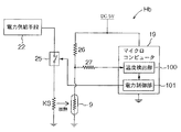
詳述すると、前記制御部Hは、図2に示すように、マイクロコンピュータ19及びその周辺回路を備えて構成され、入水温サーミスタ8に対して、加熱用直流電源20(約30V)からの自己加熱用の電力をスイッチングトランジスタ21を介して間欠的に供給する電力供給手段としての電力供給部22と、自己加熱用の電力が供給されていない状態で加熱用電力における電圧よりも低い測定用直流電源23(約5V)が印加された状態で入水温サーミスタ8の抵抗値(温度により変化する)に対応する出力電圧を検出するための温度検出用回路24とが、マイクロコンピュータ19の外付け回路として備えられている。
そして、マイクロコンピュータ19には、前記出力電圧に基づいて入水温サーミスタ8が存在する領域、つまり、出湯路6の内部の温度を検出する温度検出部100、この温度検出部100の検出情報に基づいて、入水温サーミスタ8の個体温度を設定温度まで上昇させて、設定時間が経過する間その設定温度に維持させる定温加熱制御を実行し、且つ、前記設定時間が経過すると前記定温加熱制御による電力供給を停止すべく、前記電力供給部22による電力供給状態を制御する制御手段としての電力制御部101、前記定温加熱制御による前記電力供給が停止された後において、入水温サーミスタ8の個体温度の時間経過に伴う変化状態を測定する温度変化状態測定手段としての温度変化測定部102、この温度変化測定部102の測定結果に基づいて、入水路5における流量を判別する流量判別手段としての流量判別部103の夫々が備えられて、前記電気式流量検出手段Hbが構成されている。
【0025】
前記電力供給部22は、加熱用直流電源20からの電力を、制御部Hからのパルス信号に基づいて間欠的にON/OFFするスイッチングトランジスタ21を介して入水温サーミスタ8に供給するように構成され、パルス信号のデューティ比を変更調節することで加熱用電力を変更調節するように構成されている。尚、図中25は、マイクロコンピュータ19からのパルス信号にて断続する保護抵抗付きのトランジスタを含むスイッチング回路である。
【0026】
前記温度検出用回路24は、温度検出時に入水温サーミスタ8の抵抗値を検出するための電流を測定用直流電源23から供給するための負荷抵抗26が備えられ、この負荷抵抗26と入水温サーミスタ8との接続点N1における測定電圧が入力されるマイクロコンピュータ19の入力端子N2に対して、加熱用直流電源20からの高電圧が印加されることを保護するための保護抵抗27及び保護ダイオード28,29が備えられている。
つまり、スイッチングトランジスタ21がONしている時は、入水温サーミスタ8に加熱用直流電源20の電力が供給される同時に前記接続点N1に高電圧が印加され、測定用直流電源23との間に、負荷抵抗26を経由するものと、保護抵抗27及び一方の保護ダイオード28を経由する二つの電流経路が形成される。この保護ダイオード28の順方向の抵抗値が保護抵抗27に比べて充分低く且つ接触電位の低いショットキーバリアダイオードを使用しているので、マイクロコンピュータ19に対する入力端子N2は約5V近い電位に維持されて保護回路として機能するように構成されている。尚、図中30はノイズ除去用のコンデンサである。
又、スイッチングトランジスタ21がOFFしている時には、前記負荷抵抗26と入水温サーミスタ8で分圧された出力電圧が前記接続点N1に出力されるが、この出力電圧は5V以下であるため、保護ダイオード28は逆バイアス状態であり保護ダイオード28にはマイクロコンピュータ19の入力端子N2の入力リーク電流相当の微小電流が流れるだけで接続点N1と入力端子N2の電圧レベルはほぼ等しくなる。
【0027】
前記温度検出部100は、温度検出時(スイッチングトランジスタ21がOFFしている時)に、前記入力端子N2の電圧値をアナログ・ディジタル(A/D)変換して、変換後の電圧値に基づいて入水温サーミスタ8の個体温度を演算するように構成され、この温度検出部100と前記温度検出用回路24により、入水温サーミスタ8の抵抗値の変化に基づいて入水温サーミスタ8の個体温度を検出する前記温度検出手段TDを構成する。
従って、入水温サーミスタ8への加熱用電力の供給と、入水温サーミスタ8の個体温度検出とを、時分割された互いに異なるタイミングで実行するように構成されている。
【0028】
前記電力制御部101は、スイッチング回路25を断続的にON/OFFさせる一定周期の制御パルス信号を出力し、電力供給部22から入水温サーミスタ8への電力供給量を調節するように構成され、前記温度検出部100の検出情報に基づいて、入水温サーミスタ8の個体温度を加熱目標温度(設定温度)まで上昇させて、設定時間(約3秒間)が経過する間その設定温度に維持させる定温加熱制御を実行し、且つ、前記設定時間が経過すると前記定温加熱制御による電力供給を停止すべく、電力供給部22による電力供給状態を制御するように構成されている。具体的には、温度検出部100の検出情報に基づいて、制御パルス信号のデューティ比をフィードバック制御することで、前記定温加熱制御を実行するように構成されている。従って、電力供給部22が入水温サーミスタ8を自己加熱させる加熱手段に対応することになる。
【0029】
前記温度変化測定部102は、前記定温加熱制御による前記電力供給が停止された後において、入水温サーミスタ8の個体温度の時間経過に伴う変化状態、具体的には、前記温度検出部100の検出値が設定温度未満になった時点から設定経過時間(約4秒間)が経過した時点における温度検出部100の検出値(入水温サーミスタ8の個体温度)を測定するように構成されている。
【0030】
又、前記流量判別部103は、前記温度変化測定部102による検出情報(温度検出部100の検出値)と、予め実験等によって計測して例えば不揮発性メモリ等の記憶手段に設定記憶されている換算データ、つまり、温度検出値と流量との換算表とを用いて、流量を求めるように構成されている。
【0031】
以下、電気式流量検出手段Hbによる流量検出制御の動作について、図3に示すフローチャートに基づいて説明する。
運転スイッチ15がONされると、流量判別用の初期設定を行う(ステップ1,2)。つまり、温度検出部100によりそのときの検出温度を初期温度Toとして設定するとともに、その初期温度Toに40°Cを加算した温度を加熱目標温度Tsとして設定する。又、加熱目標温度Tsでの保持時間ts(設定時間)を設定し、前記設定経過時間を計時するための検出用タイマーをリセットする。ここで、前記加熱目標温度Tsでの保持時間tsは、初期温度Toの違いに応じて、初期温度Toが高いほど短くなるように変更設定するように構成されている。この設定値は、入水温サーミスタ8の熱分布が均一になるような最短の所要時間になるように、初期温度To(サーミスタの雰囲気温度に対応)と保持時間tsとの変化特性が、実験等に基づいて予め決定されて設定記憶されており、そのときの初期温度Toと変化特性から保持時間tsが決定されることになる。
【0032】
次に、前記温度検出部100による検出値Txが加熱目標温度Tsに上昇するまで、電力供給部22による入水温サーミスタ8に対する設定量の加熱用電力の供給が行われる(ステップ3)。つまり、制御パルス信号のデューティ比を設定値に維持して、サーミスタ9を加熱する。そして、温度検出値Txが加熱目標温度Tsを越えると、その時点から保持時間tsが経過するまでの間、温度検出部100の検出値Txが加熱目標温度Tsに維持されるように、電力供給部22の供給電力量を調整する定温加熱制御を実行する(ステップ5)。具体的には、スイッチング回路25に対する制御パルス信号のデューティ比を変更調節するフィードバック制御を実行する。前記保持時間tsが経過し、且つ、温度検出値Txが加熱目標温度Tsを越えていれば、入水温サーミスタ8に対する加熱を停止する(ステップ6,7)。
【0033】
尚、温度検出部100による温度検出動作は、スイッチング回路25(スイッチングトランジスタ21)がOFF状態になっているときに、つまり、測定直流電源からの電圧だけが入水温サーミスタ8に印加されているときに実行するようになっている。
【0034】
加熱停止後、放熱によって入水温サーミスタ8の個体温度が低下し始めて温度検出部100の検出値Txが加熱目標温度Ts以下になった時点から検出用タイマーによるカウントを開始し(ステップ8,9)、検出用タイマーがカウントアップして設定経過時間tmが経過すると、その時の温度検出部100の検出値Txと、前記換算表とを用いて、流量を求める(ステップ10,11)。
つまり、図4に示すように、通水量が大であれば、入水温サーミスタ8の放熱量が大になり、検出値Txが低い温度にまで低下するが、通水量が小であれば放熱量が少なく、比較的高い温度になるのである。
【0035】
このような電気式流量検出手段Hbによる流量検出制御は、設定タイミング毎に繰り返して実行されるように構成されている。
【0036】
前記燃焼制御手段Haは、各部が正常に動作している場合には、次のような通常燃焼制御を実行するように構成されている。
運転スイッチ15がON操作されている状態で、給湯栓が開かれることによって通水量センサ7が設定量以上の通水量を検出するに伴って、ファン4の通風を開始させるとともに、開閉弁11及び電磁比例弁12を開弁操作させてバーナ3に燃料を供給し、且つ、点火イグナイタ13によりバーナ3に点火させてバーナ3の燃焼による加熱動作を開始させる。フレームロッド14により着火が確認されると点火動作を停止して、出湯温度が目標給湯温度になるようにガス燃焼量とファン4の通風量を変更調節する。つまり、入水温サーミスタ8の検出値と目標給湯温度との偏差、並びに、通水量センサ7により検出される通水量との基づいてバーナ3の必要燃焼量を求めて、その燃焼量になるようにバーナ3の燃焼量(具体的には電磁比例弁12の弁開度)とファン通風量(具体的にはファンモータの回転数)とをフィードフォワード制御するとともに、入水温サーミスタ8の検出値が目標給湯温度になるように、バーナ3の燃焼量とファン通風量とをフィードバック制御する。
その後、給湯栓が閉じられて通水量センサ7により検出される通水量が設定水量以下になると、電磁比例弁12及び開閉弁11を閉弁してバーナ3の燃焼を停止するとともに、ファン4の通風を停止させる。
【0037】
前記異常判別手段Hcは、上記電気式流量検出手段Hbの検出結果を用いて、その検出流量と、通水量センサ7の検出流量との偏差の絶対値が設定量を越えているか否かに基づいて、通水量センサ7が動作異常状態であるか否かを判別するように構成されている。そして、この異常判別手段にて動作異常状態であることが判別されると、前記燃焼制御手段Haは、通水量センサ7に代えて、前記電気式流量検出手段Hbの検出情報に基づいて、バーナ3の燃焼状態を制御する代替燃焼制御を実行するように構成されている。
【0038】
次に、燃焼制御手段Ha及び異常判別手段Hcの制御動作について、図5の制御フローチャートに基づいて説明する。
運転スイッチ15がONしている状態で通水量センサ7により水流が検知されると、その検出値Fw1を読み込み、水流が検知されなければ通水量センサ7の検出値Fw1を「0」とする(ステップ21〜24)。又、電気式流量検出手段Hbにより水流が検知されると、その検出値Fw2を読み込み、水流が検知されなければ電気式流量検出手段Hbの検出値Fw2を「0」とする(ステップ25〜27)。
【0039】
次に、通水量センサ7の検出値Fw1と電気式流量検出手段Hbの検出値Fw2との偏差の絶対値が設定量(例えば2.5リットル)より小さいか否かを判断する(ステップ28)。この偏差が小さい場合は通水量センサ7が正常に作動しているものとして、通水量センサ7の検出値Fw1を、通水量データFwとして設定する(ステップ29)。このとき、通水量センサ7の検出値Fw1と電気式流量検出手段Hbの検出値Fw2との間に誤差があれば、通水量センサ7の検出値Fw1に基づいて、電気式流量検出手段Hbにおいて流量を求めるときの、温度検出値と流量との換算表を書換え補正して、記憶手段に記憶させる(ステップ30)。
そして、その後は上記したような通常燃焼制御に移行する(ステップ31)。つまり、通水量データが設定水量を越えていればバーナ3を燃焼して目標給湯温度での給湯を実行する。通水量データFwが設定水量Qsを下回るか、又は、運転スイッチ15がOFFすると、バーナ3の燃焼を停止して通常燃焼制御を終了して次の給湯に備える。
【0040】
そして、ステップ28の判断が否であり、前記偏差が設定量より大きい場合には、通水量センサ7の検出値Fe1がほぼ零に近い異常な状態であるから、警報ランプ18を作動させて異常を報知するとともに、通水量センサ7の検出値に代えて電気式流量検出手段Hbの検出値Fw2を通水量データFwとして用いて、その通水量データFwに基づいて代替燃焼制御を実行し、このときも、通常燃焼制御と同様に、通水量データFwが設定水量Qsを下回るか、又は、運転スイッチ15がOFFすると、バーナ3の燃焼を停止して代替燃焼制御を終了することになる(ステップ37〜42)。そして、この代替燃焼制御を実行する時間の積算値T(タイマーカウンターのカウント値)が設定時間(例えば、24時間)に対応する値nを越えた場合には、バーナ3を燃焼停止するとともに、警報ランプ18を作動させた状態でインターロックする(ステップ35,36,43,44)。つまり、動作異常となった通水量センサ7の修理交換等のメンテナンス作業が行われて図示しないリセットスイッチにてリセットされるまでリモコン操作部Rのいずれの操作スイッチを操作しても動作しないようにしている。又、電気式流量検出手段Hbに基づく代替燃焼制御は、通水量センサ7の修理交換等のメンテナンス作業が行われるまでの間、燃焼作動を可能とするための補助的な制御であり、長時間継続して実行しないようにしている。
【0041】
〔別実施形態〕
(1)上記実施形態では、前記流量判別手段は、前記定温加熱制御による電力供給が停止された後において、温度検出部100の検出値Txが設定温度未満になった時点から設定経過時間(約4秒間)が経過した時点における温度検出部100の検出値Tx(入水温サーミスタ8の個体温度)と、換算表とに基づいて、流量を求めるように構成したが、このような構成に代えて、次のように構成してもよい。
【0042】
例えば、前記定温加熱制御による電力供給が停止された後に、温度検出部100の検出値Txが判定用の閾値に低下するのに要する所要時間、あるいは、前記定温加熱制御による電力供給が停止された後に、温度検出部100の検出値Txの単位時間当たりの下降量(微分値)等に基づいて、上記換算表に対応する流量との換算情報に基づいて、流量を求める構成等、各種の形態で実施することができる。
【0043】
(2)上記実施形態では、前記電力制御部101がスイッチング回路25を間欠的にON/OFFさせる制御パルス信号を出力し、入水温サーミスタ8への電力供給量を調整するようにしたが、この構成に代えて、次のように構成してもよい。
【0044】
例えば、図6に示すように、電力供給手段22がマイクロコンピュータ19で出力電圧値を制御される定電圧電源であり、サーミスタ9と第1抵抗R1が直列接続されるとともに、別の2つの第2、第3抵抗R2,R3が直列接続され、夫々が並列に電力供給手段22から電流が供給される構成とし、サーミスタ9と第1抵抗R1の中点N3と第2抵抗R2と第3抵抗R3との中点N4の各電圧値をマイクロコンピュータ19が読み取る構成とする。そして、中点N4の電圧値より電力供給手段22の電源電圧値が第2抵抗R2と第3抵抗R3との分圧比より検出でき、中点N3の電圧値と第1抵抗R1の抵抗値よりサーミスタ9に供給される電流値、及び、中点N3の電圧値と検出された電力供給手段22の電源電圧値よりサーミスタ9の両端電位差が検出でき、サーミスタ9に供給される電力量と抵抗値つまり、個体温度が同時に検出できる。
【0045】
(3)上記実施形態では、加熱目標温度(設定温度)に維持する保持時間ts(設定時間)を、初期温度(雰囲気温度)が高いほど短く時間になるように自動で変更設定するようにしたが、実験等に基づいて決定された一定時間に設定する構成としてもよく、あるいは、雰囲気温度に応じて人為的に変更設定するような構成としてもよい。
【0046】
(4)上記実施形態では、可変抵抗素子としてのサーミスタを直接的に自己加熱するようにしたが、図7に示すように、電力供給手段22から電力供給される加熱用素子KSを設け、サーミスタ9が加熱用素子により間接的に加熱されるように構成してもよい。
尚、電力供給手段22からスイッチング回路25を介して加熱用素子KSに電力が供給され、電力制御部101がスイッチング回路25に対して供給する制御パルス信号を温度検出部100の検出情報に基づいてフィードバック制御する構成等、その他の構成は点は上記実施形態と同様である。このような構成によれば、サーミスタの加熱と温度検出とを同時に実行されるため、電力供給量の調整構成に対する設定自由度が高く、スイッチング回路25を使用したデューティ比制御以外の制御手段を用いても構わない。
【0047】
(5)上記実施形態では、給湯装置における入水温サーミスタを加熱して温度変化状態を測定するようにしたが、入水温サーミスタに代えて出湯温サーミスタを利用してもよく、このような一般給湯用湯路中のサーミスタに限らず、例えば、浴槽の追焚き用の循環路内に設けられたサーミスタを利用して温度変化状態を測定して、流動量の測定を行うようにしてもよい。
【0048】
(6)上記実施形態では、制御部Hにマイクロコンピュータ19を用いたが、論理回路及び記憶回路等を組み合わせて構成するものでもよい。
【図面の簡単な説明】
【図1】給湯装置の概略構成図
【図2】制御部の回路構成図
【図3】制御動作のフローチャート
【図4】温度変化状態を示す図
【図5】制御動作のフローチャート
【図6】別実施形態の回路構成図
【図7】別実施形態の回路構成図
【符号の説明】
2 熱交換器
3 バーナ
5 入水路
6 出湯路
9 可変抵抗素子
18 警報手段
22 加熱手段
103 流量判別手段
Ha 燃焼制御手段
Hb 電気式流量検出手段
Hc 異常判別手段
TD 温度検出手段[0001]
BACKGROUND OF THE INVENTION
The present invention relates to a fluid detection device for detecting the amount of fluid flow and a hot water supply device using the fluid detection device.
[0002]
[Prior art]
Conventionally, for example, in a hot water supply device or the like, as a fluid detection device used to detect the flow rate of water as an example of a fluid, the number of rotations according to the flow rate of water in the flow channel Actuators that are mechanically actuated with the flow of water, such as rotating blades provided to rotate at the same time, are provided, and signals corresponding to the operating state (rotation speed) of the actuating body (rotating blades) are output. Some output means such as a Hall element are provided.
[0003]
[Problems to be solved by the invention]
In the conventional fluid detection device as described above, the flow rate is detected based on the state of the operating body that is mechanically operated according to the flow state of the fluid. There is an advantage that it can be detected well, but there is still room for improvement in the following points.
[0004]
The fluid (hot water) flowing in the water passage of the hot water supply apparatus may contain foreign matters such as hair and other various foreign substances. And, such impurities are entangled with the operating body by mistake, or foreign matter in the fluid accumulates on the surface of the operating body after long-term use, and the operating body is in an appropriate operating state corresponding to the flow amount. In other words, there is a possibility that inconveniences such as failure to properly perform the flow amount detection operation may occur.
Then, the flow amount of the fluid cannot be detected properly. For example, when the burner combustion state is switched and controlled based on the detected flow amount as in the case of a hot water supply device, the flow amount of the fluid can be detected based on the detected flow amount. In such a configuration in which the above control is performed, such other control operations are not properly executed, but when such other control operations cannot be properly executed, the cause is the fluid detection device. There is a disadvantage that the user cannot immediately determine whether or not the operation is abnormal and the subsequent processing cannot be performed quickly.
[0005]
The present invention has been made paying attention to such a point, and an object of
[0006]
The purpose of
[0007]
[Means for Solving the Problems]
According to the characteristic configuration of the fluid detection device according to
[0008]
Therefore, when the operation is performed normally, the flow rate of the fluid can be detected with high accuracy using the mechanical flow rate detection means. In addition, the flow rate is detected based on the change in the resistance value of the variable resistance element provided at the fluid flow target location by the electric flow rate detection means, and the detection operation of the mechanical flow rate detection means is caused by some factor. Even in a state where it cannot be properly performed, the flow rate can be detected by the electric flow rate detection means. Based on the deviation of the detected flow rate, for example, the flow rate detected by the mechanical flow rate detection means When the flow rate detected by the flow rate detection means is smaller than the set value, it can be determined that the mechanical flow rate detection means is in an abnormal operation state.
[0009]
As a result, the flow rate of the fluid can be accurately detected using the mechanical flow rate detection means, and when the fluid detection operation is abnormal, it is determined that the operation is abnormal, and the subsequent processing is quickly performed. Thus, it has become possible to provide a fluid detection device that can achieve the above.
[0010]
According to the characteristic configuration of the fluid detection device according to
[0011]
According to the characteristic configuration of the fluid detection device according to claim 3, in
[0012]
That is, after the variable resistance element whose electric resistance value changes with temperature is heated by the heating means until the set temperature is reached, the temperature change state due to the subsequent heat radiation is the flow of fluid in the region (atmosphere) where the variable resistance element exists. By utilizing the change according to the amount, the flow amount of the fluid can be determined based on the change state of the individual temperature of the variable resistance element detected by the temperature detecting means.
[0013]
According to the characteristic configuration of the fluid detection device according to
[0014]
The electric flow rate detecting means converts the change information of the resistance value of the variable resistance element into the flow amount of the fluid in light of preset conversion information. Compared with the type flow rate detection means, the variation in detection accuracy is large due to differences in ambient temperature, individual differences in thermal constants of variable resistance elements, and the like. Therefore, by correcting the conversion information so as to correspond to the flow rate detected by the mechanical flow rate detection means that can be detected with high accuracy, the detection accuracy of the electrical flow rate detection means is improved. As a result, the mechanical flow rate detection means It is possible to accurately determine whether or not the operation is abnormal.
[0015]
According to the characteristic configuration of the hot water supply device according to
[0016]
The combustion state of the burner is controlled based on the detection information of the water flow rate to the heat exchanger, but the water flow rate can be accurately detected using the mechanical flow rate detection means, and the mechanical flow rate detection means is abnormal. In some cases, it can be determined that the operation is abnormal and the subsequent processing can be performed quickly.Therefore, avoiding the disadvantage of continuing the combustion control for a long time in the operation abnormal state, It has become possible to provide a hot water supply apparatus capable of executing the control of the combustion state of the burner based on the detection information in an appropriate state.
[0017]
According to the characteristic configuration of the hot water supply apparatus according to
[0018]
Since the combustion state of the burner is controlled based on the detection information of the water flow rate accurately detected by the mechanical flow rate detection means during normal operation, appropriate combustion control can be executed. And, when it is determined that the mechanical flow rate detection means is in an abnormal operation state, instead of the mechanical flow rate detection means, the combustion state of the burner is controlled using the detection information of the electrical flow rate detection means. Appropriate combustion control can be executed while avoiding the inconvenience of continuing the control based on the mechanical flow rate detecting means whose operation is abnormal and the reliability is lowered.
[0019]
DETAILED DESCRIPTION OF THE INVENTION
Hereinafter, a fluid detection device according to the present invention and a hot water supply device using the fluid detection device will be described. As shown in FIG. 1, the hot water supply apparatus includes a hot water supply section K that heats supplied water to supply hot water, a control section H that controls the operation of the hot water supply section K, and a remote control operation section R that provides an operation command to the control section H. It is configured with.
The hot water supply section K includes a
[0020]
Although not shown, the water
[0021]
The remote control operation unit R includes an
[0022]
The control unit H is configured to include a
[0023]
Next, the electric flow rate detection means Hb will be described.
Utilizing the fact that the incoming
[0024]
More specifically, as shown in FIG. 2, the control unit H is configured to include a
Then, the
[0025]
The
[0026]
The
That is, when the switching
Further, when the switching
[0027]
The
Accordingly, the heating power supply to the incoming
[0028]
The
[0029]
The temperature
[0030]
In addition, the flow
[0031]
Hereinafter, the operation of flow rate detection control by the electrical flow rate detection means Hb will be described based on the flowchart shown in FIG.
When the
[0032]
Next, the set amount of heating power is supplied to the incoming
[0033]
The temperature detection operation by the
[0034]
After the heating is stopped, counting by the detection timer is started when the individual temperature of the incoming
That is, as shown in FIG. 4, if the amount of water flow is large, the heat dissipation amount of the incoming
[0035]
Such flow rate detection control by the electric flow rate detection means Hb is configured to be repeatedly executed at each set timing.
[0036]
The combustion control means Ha is configured to execute the following normal combustion control when each part is operating normally.
When the hot water tap is opened while the
Thereafter, when the hot water tap is closed and the water flow detected by the
[0037]
The abnormality determination unit Hc uses the detection result of the electric flow rate detection unit Hb to determine whether the absolute value of the deviation between the detected flow rate and the detected flow rate of the water
[0038]
Next, control operations of the combustion control means Ha and the abnormality determination means Hc will be described based on the control flowchart of FIG.
When the water flow is detected by the
[0039]
Next, it is determined whether or not the absolute value of the deviation between the detected value Fw1 of the
Thereafter, the routine shifts to the normal combustion control as described above (step 31). That is, if the water flow amount data exceeds the set water amount, the burner 3 is burned and hot water supply at the target hot water supply temperature is executed. When the water flow amount data Fw falls below the set water amount Qs or the
[0040]
If the determination in
[0041]
[Another embodiment]
(1) In the above-described embodiment, the flow rate determination unit is configured to perform a set elapsed time (about approximately 1 hour) after the detection value Tx of the
[0042]
For example, after the power supply by the constant temperature heating control is stopped, the time required for the detection value Tx of the
[0043]
(2) In the above embodiment, the
[0044]
For example, as shown in FIG. 6, the power supply means 22 is a constant voltage power source whose output voltage value is controlled by the
[0045]
(3) In the above embodiment, the holding time ts (set time) maintained at the heating target temperature (set temperature) is automatically changed and set so that the shorter the time is, the higher the initial temperature (atmosphere temperature) is. However, it may be configured to be set to a certain time determined based on experiments or the like, or may be configured to be artificially changed according to the ambient temperature.
[0046]
(4) In the above embodiment, the thermistor as the variable resistance element is directly self-heated. However, as shown in FIG. 7, a heating element KS supplied with power from the power supply means 22 is provided, and the thermistor is provided. You may comprise so that 9 may be heated indirectly by the element for a heating.
In addition, power is supplied from the power supply means 22 to the heating element KS via the switching
[0047]
(5) In the above-described embodiment, the temperature change state is measured by heating the incoming water temperature thermistor in the hot water supply device, but an outgoing hot water temperature thermistor may be used instead of the incoming water temperature thermistor. For example, the flow rate may be measured by measuring the temperature change state using a thermistor provided in a circulation path for reheating the bathtub, without being limited to the thermistor in the hot water channel.
[0048]
(6) In the above embodiment, the
[Brief description of the drawings]
FIG. 1 is a schematic configuration diagram of a hot water supply apparatus.
FIG. 2 is a circuit configuration diagram of a control unit.
FIG. 3 is a flowchart of the control operation.
FIG. 4 is a diagram showing a temperature change state
FIG. 5 is a flowchart of the control operation.
FIG. 6 is a circuit configuration diagram of another embodiment.
FIG. 7 is a circuit configuration diagram of another embodiment.
[Explanation of symbols]
2 Heat exchanger
3 Burner
5 waterway
6 Hot springs
9 Variable resistance elements
18 Alarm means
22 Heating means
103 Flow rate discrimination means
Ha combustion control means
Hb Electric flow rate detection means
Hc abnormality determination means
TD temperature detection means
Claims (6)
電気抵抗値が温度によって変化する可変抵抗素子が前記流体の流動対象箇所に設けられ、この可変抵抗素子の抵抗値の変化に基づいて、前記流体の流動量を検出する電気式流量検出手段と、
前記機械式流量検出手段による検出流動量と前記電気式流量検出手段による検出流動量との偏差に基づいて、前記機械式流量検出手段が動作異常状態であるか否かを判別する異常判別手段とが設けられている流体検知装置。Mechanical flow rate detecting means for detecting the flow amount of the fluid based on the operating state of the operating body that mechanically operates according to the fluid flow state;
A variable resistance element whose electrical resistance value varies with temperature is provided at a location where the fluid flows, and an electric flow rate detecting means for detecting the flow amount of the fluid based on a change in the resistance value of the variable resistance element;
An abnormality determining means for determining whether or not the mechanical flow rate detecting means is in an abnormal operation state based on a deviation between the detected flow amount detected by the mechanical flow rate detecting means and the detected flow amount detected by the electric flow rate detecting means; A fluid detection device provided with
前記可変抵抗素子を加熱する加熱手段と、前記可変抵抗素子の抵抗値の変化に基づいて前記可変抵抗素子の個体温度を検出する温度検出手段とが備えられ、
この温度検出手段の検出情報に基づいて、前記個体温度が設定温度になるまで前記可変抵抗素子を加熱するとともに、前記設定温度にまで加熱された後における前記可変抵抗素子の個体温度の変化状態に基づいて流体の流動量を判別するように構成されている請求項1又は2記載の流体検知装置。The electric flow rate detecting means is
Heating means for heating the variable resistance element; and temperature detection means for detecting an individual temperature of the variable resistance element based on a change in the resistance value of the variable resistance element.
Based on the detection information of the temperature detection means, the variable resistance element is heated until the individual temperature reaches a set temperature, and the change state of the individual temperature of the variable resistance element after being heated to the set temperature. The fluid detection device according to claim 1, wherein the fluid detection device is configured to determine a flow amount of the fluid based on the flow rate.
前記可変抵抗素子の抵抗値の変化情報、及び、予め設定されている換算情報に基づいて、前記流体の流動量を求める流量判別手段を備えて構成され、
前記流動判別手段は、その求めた前記流体の流動量が、前記機械式流量検出手段による検出流動量に対応するように、前記換算情報を補正するように構成されている請求項1〜3のいずれか1項に記載の流体検知装置。The electric flow rate detecting means is
Based on change information of the resistance value of the variable resistance element and preset conversion information, the flow rate determining means for determining the fluid flow rate is provided.
The flow determination means is configured to correct the conversion information so that the obtained flow amount of the fluid corresponds to a detected flow amount by the mechanical flow rate detection means. The fluid detection device according to claim 1.
入力路から供給される水をバーナにより加熱されて出湯路から出湯する熱交換器が備えられ、
前記機械式流量検出手段及び前記電気式流量検出手段が前記熱交換器に対する通水量を検出するように構成され、
前記熱交換器に対する通水量の検出情報に基づいて、前記バーナの燃焼状態を制御する燃焼制御手段が備えられている給湯装置。A hot water supply device comprising the fluid detection device according to any one of claims 1 to 4,
A heat exchanger that heats water supplied from the input path by a burner and discharges from the hot water path is provided.
The mechanical flow rate detection means and the electrical flow rate detection means are configured to detect a water flow rate to the heat exchanger,
A hot water supply apparatus provided with combustion control means for controlling a combustion state of the burner based on detection information of a water flow rate with respect to the heat exchanger.
前記燃焼制御手段は、前記異常判別手段にて動作異常状態であることが判別されると、前記機械式流量検出手段に代えて、前記電気式流量検出手段の検出情報に基づいて、前記バーナの燃焼状態を制御するように構成されている請求項5に記載の給湯装置。The combustion control means controls the combustion state of the burner based on detection information of the mechanical flow rate detection means during a normal operation in which it is not determined that the abnormality determination means is in an abnormal operation state. Composed of
When it is determined by the abnormality determining means that the combustion control means is in an abnormal operation state, instead of the mechanical flow rate detecting means, the combustion control means is based on detection information of the electric flow rate detecting means. The hot water supply apparatus according to claim 5, wherein the hot water supply apparatus is configured to control a combustion state.
Priority Applications (1)
| Application Number | Priority Date | Filing Date | Title |
|---|---|---|---|
| JP31024397A JP3830251B2 (en) | 1997-11-12 | 1997-11-12 | Fluid detection device and hot water supply device |
Applications Claiming Priority (1)
| Application Number | Priority Date | Filing Date | Title |
|---|---|---|---|
| JP31024397A JP3830251B2 (en) | 1997-11-12 | 1997-11-12 | Fluid detection device and hot water supply device |
Publications (2)
| Publication Number | Publication Date |
|---|---|
| JPH11142194A JPH11142194A (en) | 1999-05-28 |
| JP3830251B2 true JP3830251B2 (en) | 2006-10-04 |
Family
ID=18002908
Family Applications (1)
| Application Number | Title | Priority Date | Filing Date |
|---|---|---|---|
| JP31024397A Expired - Fee Related JP3830251B2 (en) | 1997-11-12 | 1997-11-12 | Fluid detection device and hot water supply device |
Country Status (1)
| Country | Link |
|---|---|
| JP (1) | JP3830251B2 (en) |
Families Citing this family (5)
| Publication number | Priority date | Publication date | Assignee | Title |
|---|---|---|---|---|
| JP4670293B2 (en) * | 2004-09-27 | 2011-04-13 | パナソニック電工株式会社 | Gas flow sensor device |
| FR2951266B1 (en) * | 2009-10-14 | 2011-11-11 | Suez Environnement | DEVICE FOR DETECTING THE LATCHING OF A MECHANICAL FLUID COUNTER, AND COUNTER WITH LOCK DETECTION |
| JP5297504B2 (en) * | 2011-02-21 | 2013-09-25 | Ckd株式会社 | Thermal flow meter and flow rate detector protection device for thermal flow meter |
| JP2017103194A (en) * | 2015-12-02 | 2017-06-08 | 株式会社三興ネーム | Temperature control method for conductive film heater |
| CN117537877B (en) * | 2024-01-09 | 2024-03-22 | 河北天辰仪器设备有限公司 | A plane water flux intelligent detection device for drainage material |
-
1997
- 1997-11-12 JP JP31024397A patent/JP3830251B2/en not_active Expired - Fee Related
Also Published As
| Publication number | Publication date |
|---|---|
| JPH11142194A (en) | 1999-05-28 |
Similar Documents
| Publication | Publication Date | Title |
|---|---|---|
| JP3830251B2 (en) | Fluid detection device and hot water supply device | |
| JP2000304255A (en) | Supply and exhaust cylinder clogging detecting device for forced supply exhaust type combustion device | |
| JPS6327619B2 (en) | ||
| JPH0421101B2 (en) | ||
| JP3054337B2 (en) | Combustion equipment | |
| JPH0244122A (en) | Combustion controller | |
| JP3731990B2 (en) | Fluid detector | |
| JP3182101B2 (en) | Fan control device for combustion equipment | |
| JP2000009518A (en) | Gas/liquid decision device | |
| JP3841553B2 (en) | Hot water supply device for bath | |
| JP2006250498A (en) | Combustion device | |
| JP3871810B2 (en) | Water heater with thermal insulation function | |
| JP2939124B2 (en) | Blower | |
| KR100234054B1 (en) | A controlling method for a fan of a heater | |
| KR930002800B1 (en) | Control apparatus for electric type the quantity of water control valve | |
| JP3884873B2 (en) | Incomplete combustion detector for combustion equipment | |
| JPS61225548A (en) | Hot air flow space heater | |
| JPH01118061A (en) | Hot water supplying device | |
| JP2636153B2 (en) | Incomplete combustion detector for combustion equipment | |
| KR930000632B1 (en) | Water-flow detection driving apparatus | |
| JP3841552B2 (en) | Hot water supply device for bath | |
| JP3877884B2 (en) | CO sensor device | |
| JP2857326B2 (en) | Blower | |
| JPH05223346A (en) | Air supply device | |
| JPH0252917A (en) | Gas exhausting device for hot water supply apparatus |
Legal Events
| Date | Code | Title | Description |
|---|---|---|---|
| A625 | Written request for application examination (by other person) |
Free format text: JAPANESE INTERMEDIATE CODE: A625 Effective date: 20040412 |
|
| A711 | Notification of change in applicant |
Free format text: JAPANESE INTERMEDIATE CODE: A712 Effective date: 20040413 |
|
| A977 | Report on retrieval |
Free format text: JAPANESE INTERMEDIATE CODE: A971007 Effective date: 20060623 |
|
| TRDD | Decision of grant or rejection written | ||
| A01 | Written decision to grant a patent or to grant a registration (utility model) |
Free format text: JAPANESE INTERMEDIATE CODE: A01 Effective date: 20060629 |
|
| A61 | First payment of annual fees (during grant procedure) |
Free format text: JAPANESE INTERMEDIATE CODE: A61 Effective date: 20060711 |
|
| R150 | Certificate of patent or registration of utility model |
Free format text: JAPANESE INTERMEDIATE CODE: R150 |
|
| LAPS | Cancellation because of no payment of annual fees |