JP3825801B2 - Network board that responds to changes in the status of installed peripherals by generating test pages - Google Patents
Network board that responds to changes in the status of installed peripherals by generating test pages Download PDFInfo
- Publication number
- JP3825801B2 JP3825801B2 JP50326497A JP50326497A JP3825801B2 JP 3825801 B2 JP3825801 B2 JP 3825801B2 JP 50326497 A JP50326497 A JP 50326497A JP 50326497 A JP50326497 A JP 50326497A JP 3825801 B2 JP3825801 B2 JP 3825801B2
- Authority
- JP
- Japan
- Prior art keywords
- network
- information
- printer
- interface
- peripheral device
- Prior art date
- Legal status (The legal status is an assumption and is not a legal conclusion. Google has not performed a legal analysis and makes no representation as to the accuracy of the status listed.)
- Expired - Fee Related
Links
Images


Classifications
-
- H—ELECTRICITY
- H04—ELECTRIC COMMUNICATION TECHNIQUE
- H04L—TRANSMISSION OF DIGITAL INFORMATION, e.g. TELEGRAPHIC COMMUNICATION
- H04L41/00—Arrangements for maintenance, administration or management of data switching networks, e.g. of packet switching networks
- H04L41/24—Arrangements for maintenance, administration or management of data switching networks, e.g. of packet switching networks using dedicated network management hardware
-
- G—PHYSICS
- G06—COMPUTING; CALCULATING OR COUNTING
- G06F—ELECTRIC DIGITAL DATA PROCESSING
- G06F11/00—Error detection; Error correction; Monitoring
- G06F11/30—Monitoring
- G06F11/3003—Monitoring arrangements specially adapted to the computing system or computing system component being monitored
- G06F11/3006—Monitoring arrangements specially adapted to the computing system or computing system component being monitored where the computing system is distributed, e.g. networked systems, clusters, multiprocessor systems
-
- G—PHYSICS
- G06—COMPUTING; CALCULATING OR COUNTING
- G06F—ELECTRIC DIGITAL DATA PROCESSING
- G06F11/00—Error detection; Error correction; Monitoring
- G06F11/30—Monitoring
- G06F11/3003—Monitoring arrangements specially adapted to the computing system or computing system component being monitored
- G06F11/3041—Monitoring arrangements specially adapted to the computing system or computing system component being monitored where the computing system component is an input/output interface
-
- G—PHYSICS
- G06—COMPUTING; CALCULATING OR COUNTING
- G06F—ELECTRIC DIGITAL DATA PROCESSING
- G06F11/00—Error detection; Error correction; Monitoring
- G06F11/30—Monitoring
- G06F11/3055—Monitoring arrangements for monitoring the status of the computing system or of the computing system component, e.g. monitoring if the computing system is on, off, available, not available
-
- G—PHYSICS
- G06—COMPUTING; CALCULATING OR COUNTING
- G06F—ELECTRIC DIGITAL DATA PROCESSING
- G06F11/00—Error detection; Error correction; Monitoring
- G06F11/30—Monitoring
- G06F11/34—Recording or statistical evaluation of computer activity, e.g. of down time, of input/output operation ; Recording or statistical evaluation of user activity, e.g. usability assessment
- G06F11/3466—Performance evaluation by tracing or monitoring
- G06F11/3485—Performance evaluation by tracing or monitoring for I/O devices
-
- G—PHYSICS
- G06—COMPUTING; CALCULATING OR COUNTING
- G06F—ELECTRIC DIGITAL DATA PROCESSING
- G06F13/00—Interconnection of, or transfer of information or other signals between, memories, input/output devices or central processing units
- G06F13/10—Program control for peripheral devices
- G06F13/12—Program control for peripheral devices using hardware independent of the central processor, e.g. channel or peripheral processor
- G06F13/124—Program control for peripheral devices using hardware independent of the central processor, e.g. channel or peripheral processor where hardware is a sequential transfer control unit, e.g. microprocessor, peripheral processor or state-machine
- G06F13/128—Program control for peripheral devices using hardware independent of the central processor, e.g. channel or peripheral processor where hardware is a sequential transfer control unit, e.g. microprocessor, peripheral processor or state-machine for dedicated transfers to a network
-
- G—PHYSICS
- G06—COMPUTING; CALCULATING OR COUNTING
- G06F—ELECTRIC DIGITAL DATA PROCESSING
- G06F3/00—Input arrangements for transferring data to be processed into a form capable of being handled by the computer; Output arrangements for transferring data from processing unit to output unit, e.g. interface arrangements
- G06F3/12—Digital output to print unit, e.g. line printer, chain printer
- G06F3/1201—Dedicated interfaces to print systems
- G06F3/1223—Dedicated interfaces to print systems specifically adapted to use a particular technique
- G06F3/1229—Printer resources management or printer maintenance, e.g. device status, power levels
-
- G—PHYSICS
- G06—COMPUTING; CALCULATING OR COUNTING
- G06F—ELECTRIC DIGITAL DATA PROCESSING
- G06F3/00—Input arrangements for transferring data to be processed into a form capable of being handled by the computer; Output arrangements for transferring data from processing unit to output unit, e.g. interface arrangements
- G06F3/12—Digital output to print unit, e.g. line printer, chain printer
- G06F3/1201—Dedicated interfaces to print systems
- G06F3/1278—Dedicated interfaces to print systems specifically adapted to adopt a particular infrastructure
- G06F3/1285—Remote printer device, e.g. being remote from client or server
- G06F3/1286—Remote printer device, e.g. being remote from client or server via local network
-
- G—PHYSICS
- G06—COMPUTING; CALCULATING OR COUNTING
- G06F—ELECTRIC DIGITAL DATA PROCESSING
- G06F11/00—Error detection; Error correction; Monitoring
- G06F11/30—Monitoring
- G06F11/32—Monitoring with visual or acoustical indication of the functioning of the machine
-
- G—PHYSICS
- G06—COMPUTING; CALCULATING OR COUNTING
- G06F—ELECTRIC DIGITAL DATA PROCESSING
- G06F11/00—Error detection; Error correction; Monitoring
- G06F11/30—Monitoring
- G06F11/32—Monitoring with visual or acoustical indication of the functioning of the machine
- G06F11/324—Display of status information
- G06F11/325—Display of status information by lamps or LED's
Abstract
Description
発明の背景
発明の属する分野
本発明は周辺機器とネットワークとのインタフェースとなり、その周辺機器からの周辺機器状態データを受信し、その状態データに応答して、ネットワーク情報及び/或はネットワーク機器情報を含む(プリンタ情報を含んでも良い)テストページを生成し出力するネットワーク装置に関するものである。
参考文献による組込み
米国特許第5,323,393号「ネットワーク周辺機器の状態を取得・制御する方法及び装置」、米国特許出願第08/336,062号「ネットワークプロトコルセンサ」、及び、米国特許出願第08/336,043号「スマートフラッシュ」はここで参照によって本願に組み込まれる。
関連技術の説明
現在利用可能なプリンタにはしばしば、ユーザ操作が可能なボタンを持つフロントパネルが備えられている。これらのボタンの中には、プリンタについての状態や解析情報を含むページを生成しプリントさせるボタンがある。
そのようなプリンタはコンピュータ化されたローカルエリアネットワーク(LAN)にネットワーク拡張ボードを用いて接続可能であり、このことは米国特許第5,323,393号に説明されている。しかしながら、そのボード(プリンタに対向するものとして)やフロントパネルを介してネットワークについてのテストページ情報を生成しプリントすることはできない。むしろ、そのような情報はネットワーク上のPC(パーソナルコンピュータ)からのみアクセスされ、プリントされる。しかしながら、ネットワークやネットワークインタフェース情報をプリントするこの方法は不便なものである。特に、ネットワーク周辺機器が物理的にネットワークPCから遠く離れている場合にはそう言える。
DEClasar5100▲R▼のような特殊なプリンタは、プリンタのフロントパネルのボタンを操作することにより、ネットワーク情報を含むテストページをプリント出力できる。しかしながら、これらのプリンタは、従来のプリンタにはないのはもちろんのこと、ファクシミリ装置やコピー機のような周辺機器にはなおさらない特別な“ネットワークテストページ”機能ボタンを持っている。さらにその上、DEClasar5100▲R▼のようなプリンタは、他のプリンタとの互換性がないのはもちろんのこと、他の周辺機器とはなおさら互換性のない特別なネットワークインタフェースを有している。それゆえに、従来のネットワーク周辺機器のフロントパネルを介してネットワーク情報やネットワークインタフェース情報をプリントすることに関連した一般的な問題は、これらの特別なプリンタに係るものではない。
従って、LANと従来のネットワーク周辺機器との間でインタフェースとなるインタフェースボードであって、ネットワーク周辺機器のフロントパネルを介して、ネットワーク情報やそのインタフェースボードに関連した情報が、プリント可能となるネットワークインタフェースボードの必要性が存在する。
発明の要約
前述の必要性は、従来のネットワーク周辺機器とLANとのインタフェースとなり、その周辺機器における所定順序の状態変化に応答して、ネットワーク情報とネットワークインタフェース情報とを含むテストページ情報を生成・出力するネットワーク機器である本発明によって扱われている。その周辺機器における所定順序の状態変化に応答して、そのネットワーク機器はテストページ情報を生成出力するので、そのテストページ情報は、ネットワーク周辺機器の状態を変化させるためにその周辺機器のフロントパネルの機能ボタンを操作することによって、従来のネットワーク周辺機器において、生成出力できる。
本発明における1つの特徴は、ユーザが周辺機器の状態に関与することができるように設けられたフロントパネルを含む周辺機器とネットワークとのインタフェースとなるインタラクティブネットワーク装置である。そのインタラクティブネットワーク装置は、前記ネットワークとのインタフェースとなり、前記ネットワークを介して周辺機器データを通信するためのネットワークインタフェースと、前記周辺機器とのインタフェースとなり、前記周辺機器と前記周辺機器データを通信し、前記周辺機器から前記周辺機器の状態を受信するための周辺機器インタフェースと、前記周辺機器インタフェースによって受信した前記周辺機器の状態を解析して、前記フロントパネルを介して発生する前記周辺機器における所定の順序での複数の状態変化を検出し、前記所定の順序での複数の状態変化の検出に応答して、(a)ネットワーク情報と前記インタラクティブネットワーク装置の情報との内の少なくとも1つを含むテストページ情報を生成し、(b)該生成されたテストページ情報を出力するよう制御するプロセッサとを有することを特徴とする。
前述のインタラクティブネットワーク装置が、周辺機器について所定の順序での状態変化に応答してテストページ情報を生成出力するので、その周辺機器のフロントパネルを介してインタラクティブネットワーク装置からネットワーク情報及び/或はネットワークインタフェース情報をプリントすることが可能である。
本発明のもう1つの特徴は、ネットワークとプリンタとのインタフェースとなり、テストページを生成し、前記プリンタによって前記テストページがプリント出力されるようにプリンタインタフェースを介して前記テストページを出力するインタラクティブネットワーク機器である。この機器は、前記ネットワークとのインタフェースとなり、プリントジョブが受信されるネットワークインタフェースと、前記プリンタとのインタフェースとなり、前記プリントジョブが送信され、プリンタの状態データが受信されるプリンタインタフェースと、前記ネットワークインタフェースを介して受信される前記プリントジョブを格納するプリントバッファと、少なくとも1つがプリントサーバモジュールである複数のソフトウェアモジュールを格納するメモリと、(a)前記プリントサーバモジュールを実行し、前記プリントバッファに格納されている少なくとも1つのプリントジョブを前記プリンタインタフェースを介して前記プリンタに送信し、(b)前記プリンタインタフェースを介して受信した前記状態データを解析し、前記状態データが示すプリンタの状態が前記プリンタのフロントパネルでの操作に従って所定の時間内に所定回数変化したかどうかを判断し、(c)前記状態データが示すプリンタの状態が、前記フロントパネルでの操作に従って所定の時間内に前記所定回数変化した場合、前記インタラクティブネットワーク機器の情報とネットワーク情報との内の少なくとも1つを含むテストページを生成し、(d)前記プリンタインタフェースを介して前記プリンタに前記テストページを出力するよう制御するプロセッサとを有することを特徴とする。
上記のような特徴によって、ネットワーク拡張機器がインストールされているプリンタのフロントパネルの機能ボタンを操作することにより、そのプリンタにテストページをプリント出力することが可能となる。
また、もう1つの特徴によれば、本発明はネットワークインタフェースによってネットワークに接続され、周辺機器インタフェースによって前記周辺機器に接続されたネットワーク機器から、前記ネットワーク機器の情報とネットワーク情報との内の少なくとも1つを含むテストページ情報を出力する情報出力方法である。その方法は、前記周辺機器のフロントパネルのボタンが所定時間内に所定回数操作されることにより、所定の順序で周辺機器を状態変化させる工程と、前記周辺機器インタフェースを介して前記ネットワーク機器と前記周辺機器との間で前記所定の順序での状態変化を通信する工程と、前記ネットワーク機器において、前記所定の順序での状態変化に応答して、前記ネットワーク機器の情報と前記ネットワーク情報との内の少なくとも1つを含むテストページ情報を生成する工程と、前記テストページ情報を、前記周辺機器インタフェースを介して前記周辺機器と前記ネットワーク機器との間で通信する工程と、前記周辺機器において、前記テストページ情報を出力する工程とを有することを特徴とする。
さらに別の特徴によれば、本発明はネットワークインタフェースによってネットワークに接続され、周辺機器インタフェースによって前記周辺機器に接続されたネットワーク機器から、前記ネットワーク機器の情報とネットワーク情報との内の少なくとも1つを含むテストページ情報を出力する情報出力方法である。その方法は、前記ネットワーク機器において、前記周辺機器インタフェースによって受信した前記周辺機器の状態を解析して、前記周辺機器のフロントパネルを介して発生する前記周辺機器における所定の順序での複数の状態変化を検出する工程と、前記ネットワーク機器において、前記ネットワーク機器の情報と前記ネットワーク情報との内の少なくとも1つを含むテストページ情報を生成する工程と、前記ネットワーク機器において、前記所定の順序での複数の状態変化の検出に応答して、前記テストページ情報を、前記周辺機器インタフェースを介して前記周辺機器に出力する工程とを有することを特徴とする。
さらに別の特徴によれば、本発明はネットワークインタフェースによってネットワークに接続され、周辺機器インタフェースによって前記周辺機器に接続されたネットワーク機器から、前記ネットワーク機器の情報とネットワーク情報との内の少なくとも1つを含むテストページ情報を出力する情報出力方法である。その方法は、前記ネットワーク機器において、前記周辺機器インタフェースによって受信した前記周辺機器の状態を解析して、前記周辺機器の状態が前記周辺機器のフロントパネルでの操作に従って所定の時間内に所定回数変化したことを検出する工程と、前記ネットワーク機器において、前記ネットワーク機器の情報と前記ネットワーク情報との内の少なくとも1つを含むテストページ情報を生成する工程と、前記ネットワーク機器において、前記周辺機器の状態が前記フロントパネルでの操作に従って前記所定の時間内に前記所定回数変化したことの検出に応答して、前記テストページ情報を、前記周辺機器インタフェースを介して前記周辺機器に出力する工程とを有することを特徴とする。
さらにまた別の特徴によれば、本発明はフロントパネルを含むプリンタとネットワークとのインタフェースとなり、テストページ情報を生成するネットワークボードである。そのネットワークボードは、前記ネットワークからのプリンタジョブと制御信号が受信され、前記ネットワークにプリンタの状態情報が送信されるネットワークインタフェースと、前記プリンタに対してプリントジョブと制御信号とが送信され、プリンタの状態情報が前記プリンタから受信されるプリンタインタフェースと、(a)前記プリンタの状態情報を受信し、前記プリンタの状態情報を解析し、所定の順序での複数の状態変化が前記プリンタのフロントパネルでの操作に従って発生したかどうかを判断し、(b)前記所定の順序での複数の状態変化が発生したことが判断された場合には、前記プリンタインタフェースを介して前記プリンタにプリンタの状態情報について問い合わせ、(c)前記プリンタインタフェースを介して前記プリンタの状態情報を受信し、(d)前記プリンタ状態の情報とネットワーク情報とネットワークボードの情報との内の少なくとも1つを含むテストページ情報を生成し、(e)該生成されたテストページ情報を出力するよう制御するプロセッサとを有することを特徴とする。
前述のプリンタインタフェースは双方向通信が可能であるので、前述のネットワークボードにより大容量のプリンタ状態情報をプリンタからそのネットワークボードに送信することが可能になる。従って、プロセッサはプリンタからのプリンタ状態情報を要求し、テストページ情報を生成する出力する際にはそのプリンタ状態情報を含めることができる。
さらにまた別の特徴によれば、本発明はネットワークとユーザが状態変化に関与できるように設けられたフロントパネルを含む周辺機器との間のインタフェースとなるネットワークボードである。そのネットワークボードは、前記ネットワークとのインタフェースとなり、周辺機器データと周辺機器情報が通信されるネットワークインタフェースと、前記周辺機器とのインタフェースとなり、前記周辺機器データが受信され、前記周辺機器情報の要求が通信され、前記周辺機器の状態情報が受信される周辺機器インタフェースと、前記周辺機器インタフェースを介して受信された状態情報を解析して、前記フロントパネルを介して発生する前記周辺機器における所定の順序での複数の状態変化を検出する検出手段と、ネットワーク情報とネットワークボード情報との内の少なくとも1つを含むテストページ情報を生成する生成手段と、前記所定の順序での複数の状態変化の検出に応じて、前記生成手段により生成されたテストページ情報を出力する出力手段とを有することを特徴とする。
さらにまた別の特徴によれば、本発明はユーザが周辺機器の状態に関与することが可能であるように設けられたフロントパネルを含む周辺機器とネットワークとの間のインタフェースとなるネットワーク装置である。その装置は、前記ネットワークとのインタフェースとなり、前記ネットワークを介して周辺機器データを通信するためのネットワークインタフェースと、前記周辺機器とのインタフェースとなり、前記周辺機器と前記周辺機器データを通信し、前記周辺機器から前記周辺機器の状態を受信するための周辺機器インタフェースと、前記周辺機器インタフェースによって受信した前記周辺機器の状態を解析して、前記フロントパネルを介して発生する前記周辺機器における所定の順序での複数の状態変化を検出する検出手段と、ネットワーク情報と前記ネットワーク装置の情報との内の少なくとも1つを含むテストページ情報を生成する生成手段と、前記所定の順序での複数の状態変化の検出に応じて、前記生成手段により生成されたテストページ情報を出力する出力手段とを有することを特徴とする。
さて、この簡単な要約は発明の性質を即座に理解できるように備えられている。しかし、本発明についてのより完全な理解は、添付図面を参照しながら次の詳細な実施形態の説明から得られる。
【図面の簡単な説明】
図1は、ネットワーク機器が接続されたローカルエリアネットワークとワイドエリアネットワークを示す図である。
図2Aは、キャノン製LBP1260レーザプリンタのようなレーザプリンタの正面図である。
図2Bは、そのパラレルポートにネットワーク機器がインストールされたプリンタの背面図である。
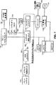
図3は、プリンタとローカルエリアネットワークとの間に接続されたネットワーク機器を示すブロック図である。
図4A及び図4Bは夫々、RJ−45コネクタをもつネットワーク機器上の各要素の物理的レイアウトを示す回路ボードの上面図と底面図である。
図5A及び図5Bは夫々、BNCコネクタをもつネットワーク機器上の各要素の物理的レイアウトを示す回路ボードの上面図と底面図である。
図6は、RJ−45コネクタをもつネットワーク機器の機能構成を示すブロック図である。
図7は、BNCコネクタをもつネットワーク機器の機能構成を示すブロック図である。
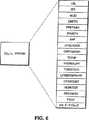
図8は、フラッシュEPROMに格納可能な幾つかのソフトウェアモジュールの例を示す図である。
図9は、CPSOCKETにおいて実行される自動ロギングを示すフローチャートである。
図10A及び図10Bは、異なる選択可能レベルのデータについて自動ロギングを示すフローチャートである。
図11は、ログファイルを出力するための処理を示すフローチャートである。
図12は、種々の条件に応答して契機となる条件を検出する処理を示すフローチャートである。
図13は、ログファイルの例を示す図である。
図14は、テストページ生成出力処理を示すフローチャートである。
図15は、XPLモジュール内でテストページモジュールの動作を示すフローチャートである。
図16は、テストページの例を示す図である。
図17は、デバッグ情報出力処理を示すフローチャートである。
図18は、種々の可能な条件について契機となる条件を検出する処理を示すフローチャートである。
図19は、受信画像形成データについてデバッグ情報出力処理を示すフローチャートである。
図20は、デバッグ情報出力のサンプルを示す図である。
図21は、ネットワークボードが接続されたローカルエリアネットワークとワイドエリアネットワークを示す図である。
図22は、キャノン製LBP1260レーザプリンタに組み込まれたネットワークボードを示す破断斜視図である。
図23は、プリンタとローカルエリアネットワークとの間に接続されたネットワークボードを示すブロック図である。
図24は、ネットワークボード上の種々の要素の物理的レイアウトを示すブロック図である。
図25は、ネットワークボードの前面プレートを示す図である。
図26は、ネットワークボードの機能を示すブロック図である。
図27は、CPSOCKETにおいて実行される自動ロギング処理を示すフローチャートである。
図28A及び図28Bは、異なる選択可能レベルのデータについての自動ロギングを示すフローチャートである。
図29は、ログファイルの例を示す図である。
図30は、プリンタ情報をプリンタに問い合わせし、テストページにプリンタ情報を含むようにしたXPLモジュール内のテストページモジュールの動作を示すフローチャートである。
好適な実施形態の詳細な説明
1つの実施形態として、本発明は、ハードウェア、ソフトウェア、及び、ファームウェアのソルーションを提供し、プリンタのようなネットワーク周辺機器を、ネットワークからデータを受信処理し、NED状態とNED機能情報と共にネットワークに限定した量の周辺機器状態情報とを送信することが可能なインテリジェント対話型ネットワーク構成要素にするネットワーク拡張機器(NED)に適用される。ファクシミリ装置、コピー機、他のネットワーク接続可能な周辺機器、特に、情報の出力可能な画像処理周辺機器のような他のネットワーク周辺機器において、NEDを用いることも可能である。周辺機器とともに、NEDハードウェア、ソフトウェア、ファームウェアとをインテグレーションすることによって、ネットワークパーソナルコンピュータを周辺機器サーバとして専従して動作させる必要性がなくなる。
[ネットワークアーキテクチュア]
図1は周辺機器インタフェースを介して片側がプリンタ102に結合されたNED1001に組み込まれた本発明を示すブロック図である。NED1001のもう1つの側はローカルエリアネットワーク(LAN)100にLANインタフェース、例えば、同軸(Coax)コネクタによる10Base−2イーサネットやRJ−45コネクタによる10Base−Tイーサネットを介して接続されている。
複数のパーソナルコンピュータ(PCs)、例えば、PC103、PC104もまた、ネットワークオペレーティングシステムの制御の下、LAN100に接続されており、これらのPCはNED1001と交信可能である。PCの1つ、例えば、PC103はネットワーク管理ワークステーションとして割り当てられる。PCはプリンタ105がPC104に接続されているように、接続されたプリンタをもつこともある。
また、LAN100に接続されたファイルサーバ106は、大容量(例えば、10ギガバイト)のネットワークディスク107に格納されたファイルへのアクセスを管理する。プリントサーバ108は、プリンタ105のようなリモートプリンタも含め、接続されたプリンタ109、110へのプリントサービス機能を備える。LAN100には他の不図示の周辺機器も接続可能である。
さらに詳細に言えば、図1で図示されているネットワークは、異種結合ネットワークである。異種結合ネットワークとは、種々のネットワーク機器の間での通信を可能とするために、Novell、UNIX、或は、AppleTalkのようなどんなネットワークソフトウェアでも利用できるネットワークのことを言う。この実施形態では、もちろん他のネットワークソフトウェアも利用可能であるが、NovellのNetware▲R▼を利用するLANについて説明する。このソフトウェアパッケージの詳細な説明は、ここで参照として本発明に組み込まれているM&T社(著作権保有)出版の1990年版“Netware▲R▼ユーザーズガイド”と“Netware▲R▼管理者(スーパバイザ)ガイド”にある。さらに、Novell社発行の1991年3月版、“Netware▲R▼プリントサーバ”、Novellパートナンバ100-000892-001も参照されたい。
簡単に言えば、ファイルサーバ106はネットワークに接続されたワークステーションについて、集中型ファイル記憶装置としての働きをする。PC103、104は、そのディスクがまるでこれらのPCに直接接続されているかのようにファイルサーバ106にデータファイルを格納できる。さらに、ファイルサーバ106は、受信、格納、照会、及び、プリンタファイルのネットワークプリンタへの送信を行うことによって、共有プリンタサービスを提供する。例えば、PC103、104によって夫々創成されたプリントファイルは、そのファイルを格納するファイルサーバ106を経由して、それから、プリントサーバ108からの命令によってプリンタ109にそのプリントファイルを転送する。
PC103と104は夫々、データファイルを生成し、それをLAN100に送信し、LAN100からファイルを受信し、そのようなファイルを表示及び/或は処理することが可能な標準的なパーソナルコンピュータ(PC)を含んでいる。しかしながら、パーソナルコンピュータの装置は図1に図示したようなものであるが、実行されるネットワークソフトウェアに適するように、他の構成のコンピュータ装置もまた含まれる。例えば、UNIXソフトウェア使用時には、ネットワークにUNIXワークステーションが含まれるし、それらのワークステーションが、適切な環境の下では、図示のPCと関連して用いられても良い。同様に、AppleTalkソフトウェア(例えば、イーサトーク(EtherTalk))使用時には、マッキントッシュワークステーションがネットワークに含まれていても良い。
LAN100のようなLANは通常、ビルディングの1つのフロア或は連続するフロアにいる一群のユーザのように、まさしく群れとなって存在するグループのユーザに種々の機能を提供する。ユーザが、例えば、異なったビルディングにいるとか或は異なった国にいるとか、互いにもっと遠く離れているようになると、広域ネットワーク(WAN)を創成しても良い。WANは本質的には高速統合化サービスデジタルネットワーク(ISDN)電話回線のような高速デジタル回線によって全てが接続された複数LANの集合体である。従って、図1に示されているように、LAN100、110、120が接続され、変調器/復調器(モデム)/トランスポンダ130と複数バス間の単なる電気接続であるバックボーン140とを介して、WANを形成する。必ずしも、必要なことではないが、各LANは夫々に自分のPCを有し、夫々に普通は自身のファイルサーバとプリントサーバとを有している。
従って、図1に示されているように、LAN110は、PC111と112、ファイルサーバ113、ネットワークディスク114、プリントサーバ115、プリンタ116、117とを含んでいる。一方、LAN120は、ただPC121と122とを含むのみである。WAN接続を介して、LAN100、110、120のいづれの装置も、他のLANの装置に対してアクセスすることができる。
PC104は、RPRINTERソフトウェアを実行することができる。RPRINTERプログラムは、MS−DOSのターミネイト−アンド−ステイ−レジデント(“TSR”)プログラムであり、これによって、ユーザがPC104に接続されたプリンタの共有が可能になり、一方、同時にPC104が他の非プリント系アプリケーションの実行が可能になる。RPRINTERは相対的にはインテリジェント能力のないプログラムであり、作業のためにプリンタキューを探す能力はもっていない。RPRINTERは、ネットワークのどこかで動作しているプリントサーバ108からその作業を得る。そのソフトウェアは、プリンタパラレルポートを介して接続されたプリンタと通信するので、RPRINTERを実行しているPC104は、プリンタ105から限定的な状態情報を得て、LAN100を介してプリントサーバ108にその状態情報を返すことができる。制御という観点からすれば、RPRINTERによって、例えば、プリンタが用紙切れであったり、オフラインにあったりするとき、プリントジョブを停止することが可能になる。あるプリンタでは、パーソナルコンピュータで実行するRPRINTERのTSRプログラムと同じ限定的な特徴を備える内部或は外部回路基板を設けることによってRPRINTERの特徴を含んでいる。
プリントサーバ108は、LAN周辺機器を介してより重要な制御を実行することが可能であるが、他のどんなタスクに対しても使用できない専用のPCを必要とする。それ自身がPCでも有り得るプリントサーバ108は、多数のユーザ定義のプリントキューをサービスする能力をもち、動的サーチキュー変更を実行し、例外(失敗)条件と状態についての定義された通知手順と制御能力とを備え、ローカルプリンタ109、110(即ち、プリントサーバ108に物理的に接続されたプリンタ)と、リモートプリンタとの両方を制御できる。ローカルプリンタ109、110は、シリアルポートかパラレルポートに接続可能であり、プリンタ105のようなリモートプリンタは、RPRINTERソフトウェアを通じてプリントサーバ108がサービスするシステムのどこかで動作しているプリンタである。
プリントサーバ108は、多くのローカル或はリモートプリンタを制御可能であり、多くのファイルサーバキューからのプリント情報を要求することが可能である。しかしながら、ネットワークプリントサービスを制御するのにプリントサーバ108に依存することにはいくつかの問題がある。最初の問題とは、多くのプリンタストリームが全て、1つのネットワークノードを通って送り込まなければならないことである。これによって、ボトルネックが発生し得る。2番目の問題とは、最適効率の運用を考えると、プリンタは、プリンタ109、110のように、そのプリントサーバにローカルに接続されるべきである。これはユーザにとって不便なことである。なぜなら、このことにはプリンタがプリントサーバ108の周辺に群をなして存在することが求められ、また、ユーザがその群をなしているプリンタの所にまで足を運ぶことが求められるからである。3番目の問題とは、もし、RPRINTERによってサービスされているプリンタ105の場合がそうであるように、制御されているプリンタがリモートであるなら、プリントデータは、いくつかの場所を経て移動しなければならない。具体的には、まず、ファイルサーバ106からプリントサーバ108へ、次に、プリントサーバ108からRPRINTERを動作させているプリンタへという具合である。これは非効率である。
[ネットワーク機器]
NED1001をプリンタ102にインストールすることによって、プリンタ102がインテリジェント機能を備えた、インタラクティブなネットワーク構成機器になるので、上述したように、ネットワーク周辺機器の制御エンティティにわたって、多くの利点が備えられる。
図2Aはプリンタ102の正面図である。プリンタ102には用紙トレイ1022とフロントパネル1021とが備えられている。図示されてるように、フロントパネル1021は、複数の機能ボタンを備え、その内の少なくとも1つが従来からのオンライン/オフラインボタンであり、他のいくつかのボタンはプリンタ102の状態を変更できるボタンである。
図2Bに示されているように、NED1001は周辺機器インタフェース、ここではプリンタ102のパラレルポートを介してプリンタ102に接続されている。そのパラレルポートは、キャノン社製LBP1260レーザプリンタのような市販のプリンタでは一般的な機能である。NED1001がインストール可能なパラレルポートは、制限されている訳ではないが、古典的なセントロニクスパラレルポートやIBM PCパラレルポートを含んでいる。なお、セントロニクスパラレルポートは、例えば、セントロニクス技術標準(Centronics Engineering Standard)No. 9, Revision B, Genicom Corp.1980年4月9日版(例えば、プリンタ102におけるAmphenol 57-40360或は、その相当品、及び、NED1001におけるAmphenol 57-40360或は、その相当品)に説明されている。また、IBM PCパラレルポートは、例えば、IBMパーソナルコンピュータ技術リファレンスオプション及びアダプタマニュアル(IBM Personal Computer Technical Reference Options and Adapters Manual)No. 6322509, IBM Corp.,1994年4月版に説明されている。これによって、NED1001が後述する処理とデータ格納機能を備えたネットワークノードになる。
NED1001のアーキテクチュアは、大規模なマルチエリアWANネットワークの管理運営についてのユニークな支援機能をもっているので、利点がある。これらの支援機能には、例えば、(ネットワーク管理者のオフィスからのような)プリンタ制御、ネットワークをまたがってアクセス可能であるNED1001によって生成されたプリンタの作業負荷を特徴づけまたトナーカートリッジ交換を計画するためのプリンタログ或は利用状況の統計が含まれている。さらに、NED1001はLANに限定された量のプリンタ状態情報を転送して戻すことができる。具体的には、“ビジー”、“用紙切れ”、“I/Oエラー”、“オンライン/オフライン”信号が、専用情報ラインを介して、前述のセントロニクスインタフェースで、プリンタ102からNED1001に送信可能である。これらはNED1001によって可能され、要求に応じてLAN100に転送される。
図3は、NED1001のプリンタ102への電気的接続を示すブロック図である。NED1001は、LANインタフェースを介してLAN100に、また、パラレルインタフェース1050を介してプリンタ102に直接接続される。本発明の好適な実施形態では、パラレルインタフェース1050は、上述したように、単方向の36ピンの古典的なセントロニクスインタフェースコネクタである。しかし、他の周辺機器インタフェースの使用も可能である。
[NEDの物理的レイアウト]
図4A及び図4Bは、NED1001の好適な実施形態の上面図と底面図を示し、その主要な構成要素の物理的なレイアウトを示している。NED1001は、長さが3.25インチ、幅が2.25インチ、厚さが1インチ、重さが約3オンスである。パラレルインタフェース1050のために、NED1001は、プリンタ102のパラレルポートにフィットする36ピンのパラレルポートコネクタを用いている。コネクタ301はLAN100を絶縁変圧器(Isolation Transformer)1790を介してNED1001に接続するが、好適には、10Base−Tを接続可能なRJ−45コネクタが良い。NED1001には、3つの状態発光ダイオード(LED)304〜306が含まれている。また、NED1001には、マイクロプロセッサ173、トランシーバ171、発振器172、フラッシュ消去可能プログラム可能な読み出し専用メモリ(EPROM)174、インタフェース変換ロジック900、動的ランダムアクセスメモリ(DRAM)175、静的ランダムアクセスメモリ(SRAM)176、ネットワーク及びネットワークインタフェース制御ロジック500、及び、シリアルポートコネクタ600が備えられている。これらの構成要素各々については後で詳述する。
LED304〜306に関して、NED1001において、状態LED304はNED1001がLAN100からのデータ受信時に点灯し、状態LED305はNED1001がLAN100に接続時に点灯し、状態LED306はNED1001の自己診断テストの間点灯する。
図5A及び図5Bは、NED1001の別の実施形態の上面図と底面図を示し、ここではNED1001はLAN100にコネクタ302を介して接続するが、コネクタ301と絶縁変圧器1790とは含んでいない。コネクタ302は、10Base−2接続が可能な単純な同軸(coax)コネクタである。この実施形態における他の構成要素は、構造的にも機能的にも、図4A及び図4Bに示したものと同一である。さらに別の実施形態では、両方のタイプのLANコネクタ、即ち、RJ−45とBNCコネクタとが1つのNEDに備えることができるようにしても良い。
[NEDアーキテクチュア]
NED1001のアーキテクチュアが図6に示されている。全ての回路に対する電力は、+5V電源177から5V電源レギュレータ1780を介してNED1001に供給される。
ネットワークとネットワークインタフェース制御ロジック500は好適には単一の144ピンのアプリケーション専用集積回路(ASIC)であり、ネットワークコントローラ510、インタフェース制御ロジック520、及び、SCSIコントローラ530とを含んでいる。ネットワークコントローラ510はナショナルDP83902A“ST−NIC”イーサネットコントローラと互換性のあるNCRマクロセルである。なお、ナショナルDP83902A“ST−NIC”イーサネットコントローラの詳細は、ナショナル半導体ローカルエリアネットワークデータブック、ナショナルセミコンダクタp/n400055、ナショナルセミコンダクタ、1993年版に述べられている。ネットワークコントローラ510は、CSMA/CD(Carrier Sense Multiple Access with Collision Detection)タイプのローカルエリアネットワークとインタフェースをもつために設計されている。SCSIコントローラ530は、NCR53C80SCSIコントローラチップマクロセルであり、その詳細は“NCR5380ファミリ”SCSIチップリファレンスマニュアル、NCRマイクロエレクトロニクスに述べられている。
この実施形態では、ネットワークコントローラ510は絶縁変圧器1790を介してRJ−45コネクタと接続されている。ネットワークコントローラ510はまた、イーサネットデータのために入出力パケットバッファとして用いられる8KBのSRAM176と結合されている。このメモリのアクセス時間は、約70nsec以下であることが好ましい。
図4A及び図4Bで示したRJ−45による接続ではなく同軸ネットワーク接続を用いる図5A及び図5Bに関連して上述した実施形態に関して、図7はトランシーバ171を介して同軸コネクタ302に接続するネットワークコントローラ510を示している。トランシーバ171は、好適にはナショナルセミコンダクタDP8392同軸トランシーバインタフェースであり、その詳細もまたナショナルローカルエリアネットワークデータブックに述べられている。
インタフェース制御ロジック520は、ネットワークコントローラ510とマイクロプロセッサ173とメモリデバイスEPROM174と、DRAM175との間のインタフェースを備える。EPROM174は、NED1001がインストールされるプリンタ102に電力が投入されている間、初期データ格納のために不揮発性記憶として用いられる256バイトを含んでいる。NED1001はEPROM174の個々の場所への書き換えができ、これによって、従来はNVRAMに格納されていた情報の格納をEPROM174で可能になるので、ディスクリートNVRAMチップはNED1001には必要がない。ネットワーク及びプリンタ構成のパラメータは、プリンタが最初にネットワークにインストールされ、NEDソフトウェアがプリンタ電源のオフ/オン後にそのインストールパラメータを回復できるようになったとき、EPROM174に書き込まれる。
インタフェース制御ロジック520はまた、いくつかのシリアルポートコネクタ600に接続している。そのコネクタは、夫々にデバックのためにシリアルデータストリームを受信、送信できる受信データピン601、送信データピン602を有している。インタフェース制御ロジック520は受信データラインに存在するデータを検知し、決まった間隔でそのシリアルビットをサンプルする。
インタフェース制御ロジック520はさらにSCSIコントローラ530とも結合される。そのコントローラは、ネットワークとネットワークインタフェース制御ロジック500からインタフェース変換ロジック900へのデータ転送を制御する。なお、SCSIコントローラ530とインタフェース変換ロジック900は本発明の動作には不可欠な要素ではない。むしろ、出願人は、発明の名称が“スマートフラッシュ”という米国特許出願第08/336,043号で説明されている回路を再利用するように、NED1001がSCSIコントローラ530を含むように構成している。
この点について、インタフェース変換ロジック900は、その詳細がアドバンストマイクロデバイスパブリケーション(Advanced Micro Devices Publication)、No.16751、1994年4月版に説明されているMACH215PALが好適であり、SCSIインタフェースコントローラ530から受信した制御信号をSCSIプロトコルからセントロニクスインタフェースのようなパラレルインタフェースを駆動するための制御信号に変換するために用いられる。従って、SCSIコントローラがパラレルインタフェース1050を制御するために用いられないNEDでは、インタフェース変換ロジック900もまた、用いられることはない。
NED1001の中央コントローラはマイクロプロセッサ173であり、好適にはインテル社製の8ビットプロセッサ80C188EA−20である。その詳細は、80C186EA/80188EAユーザーズマニュアル、インテル(Intel)p/n 270950-001、インテル社(Intel Corp.)に見ることができる。発振器172はマイクロプロセッサ173に40MHzのクロック信号を供給する。このプロセッサは、8ビットプロセッサであり、ダイレクトメモリアクセス(DMA)、インタラプト、タイマ、DRAMリフレッシュ制御の機能をもつ。AMD社製8ビットプロセッサ80C188−20のような他のマイクロプロセッサを代わりに使用することもできる。256KBのフラッシュEPROM174と512KBのDRAM175は、インタフェース制御ロジック520を介してマイクロプロセッサ173に結合される。
マイクロプロセッサ173は、制御ファームウェアとプリントアプリケーションソフトウェアを格納したフラッシュEPROM174にある命令を実行する。電源投入時の自己診断(POST)の後、コードは選択的により高性能の512KBDRAM175に移動させられる。実際の実行のためには、DRAM175のアクセス時間は約80nsecであることが好ましい。フラッシュEPROM174は、上述の米国特許出願第08/336,043号に説明されているように、LAN100から再プログラム可能、或は、“フラッシュ化”可能である。
図8は、フラッシュEPROM174に格納されたコードブロック或はソフトウェアモジュールのいくつかの例を示す。XPLモジュールはプリンタ102とNED1001との間の標準的なインタフェースを提供し、また、NED1001が後で詳述するがプリンタ102における所定順序での状態変化を検出するときテストページを生成するために用いられる。MLID(Multi Link Interface Driver)は、ネットワーク接続の最下位レベルである1群のカスタマイズされたコード(ハードウェア支援モジュール(Hardware Support Module)或はHSM)とともにリンクされる1群のNovellコード(メディア支援モジュール(Media Support Module)或はMSM)である。一方、LSL(Link Support Layer(リンク支援層))は、1群のNovellコードであり、下位レベルのMLIDとその上位にスタックするいくつかのプロトコルとの間のマルチプレクサとしてふるまう。CNTEXはカスタマイズされたコードであり、ローカルなDOSに似た機能呼び出しを、OPEN、READ、WRITE、CLOSEのようなファイル機能を備えるネットワーク機能呼び出しに換える。
PRETASKモジュールは、後に述べるが、どんなフレームタイプが種々の可能性のあるプロトコルスタックと関連しているのか識別する役目がある。NED1001は多数のプロトコルスタックをサポートするので、このモジュールはNED1001が動作している限り、NED1001に常駐する。
NovellのIPX/SPXプロトコルスタックはフラッシュEPROM174に含まれ、SAP或はサービス・アドバタイジング・プロトコル(Service Advertising Protocol)によってサポートされる。SAPは、デバイスがそれ自身を、アクティブなネットワークエンティティとインアクティブなネットワークエンティティとをリストしているファイルサーバのバインダリへ登録を可能にする概念である。キャノン社▲R▼のデバイスは特殊な種類のバインダリ項目となるので、SAPはCPSOCKETを介してNED1001に登録する。そして、NED1001がプリントサーバとして、即ち、標準的なバインダリ項目として構成されているなら、SAPはまた、そのプリントサーバをNetwareのバインダリに登録する。
CPSERVERはNovellのプリントサーバアプリケーションのカスタムインプリメンテーションである。このモジュールは、自己生成のプリントバーナ、完了及び例外状態のユーザ通知、プリンタへのプリントデータと状態コマンドの送信機能を備える。CPSERVERは、ローカルプリンタ(即ち、NED1001がインストールされたプリンタ102)を駆動する専用のものであり、他のリモートRPRINTERを駆動できないので、Novellのプリントサーバとは異なる。このプログラムは、プリントジョブの実行中、プリントデータ経路を所有する。CRPRINTERは、NovellのRPRINTERプリントアプリケーションのカスタムインプリメンテーションである。このモジュールは、Novellのプリントサーバアプリケーション、即ち、LAN100のどこかにあるPSERVERによってデータを送られるアプリケーションである。
TCP/IPプロトコルスタックは、その中に、ユーザデータグラムプロトコル(UDP(User Datagram Protocol))、リザーブアドレスレゾルーションプロトコル(RARP(Reserve Address Resolution Protocol))、ブートP(BootP)サポートを有する。INTERRUPTは、TCP/IPタスクについてのインタラプト・ハンドラであり、一方、TIMERTICKは、UNIXのTCP/IPネットワークタスクについてのタイマのしるしである。LPRINTSERVERは、TCP/IPプリントサーバアプリケーションであり、また、プリントジョブ実行中のプリントデータ経路を所有する。
CPSOCKETプログラムは、全てのプロトコルスタックについて実行する。そのプログラムは、接続要求、データのダウンロード要求、或は、リモートユーティリティからのサービス要求に応答し、内部プロセス通信を介して他のタスクへの状態制御を備える。CPSOCKETは、通常、NED1001とプリンタ102との間の状態制御経路を有しているので、ステータスラインを介してプリンタの状態を取得する能力を有する唯一のタスクである。CPSOCKETは、Novellに適応した状態と制御ユーティリティ(CPNET)との間、或は、UNIXに適応した状態と制御ユーティリティ(cputil)との間のネットワーク接続とパケット内容に責任をもつ。
MONITORは、タスク創成、タスク消去、マイクロプロセッサのディスパッチを実行するカスタマイズされたマルチタスクのモニタである。MONITORはまた、メモリ管理のサブモジュールMEMGETとMEMFREEとを有している。RESIDENTは、プリンタ102に電源が投入されている間、初期化データ格納のための不揮発性記憶として用いられる256バイトのフラッシュEPROM174への書き込みと読み出し、FLASHコード、ROMに基づくデバッガ、ハードウェアタイマによる印づけ、及び、他の基本的な機能のような一般的なサービスを提供する1群のルーチンである。POSTは電源投入時、NEDハードウェア及びソフトウェアの完全性をチェックする電源投入時の自己診断モジュールである。
フラッシュEPROM174はまた、すべてのネットワークボード、ハードウェア構成、ボード改訂番号等についてユニークな、つまり、回路ボードに不変の情報と、ソフトウェアのバージョン番号のように変化し得る情報とを格納するネットワーク認識ファイル(“NIF”)データブロックを格納する。NIFデータブロックにおける情報は、フラッシュEPROM174が互換性のないイメージで再プログラムされないことを保証するために用いられる。
具体的には、フラッシュEPROM174は、モデル番号、ファームウェアレベル、ボード改訂番号のような“ボード”情報と、どのネットワークボード、ボード名、ネットワークフレームタイプ、プライマリファイルサーバ識別、キューサービス、ネットワークプロトコル、サンプリング周波数、PSERVER名、ゾーン名等に関して唯一なメディアアクセス制御(“MAC”)アドレスのような“ネットワーク”情報を格納する。
[NEDの機能性]
広義に言えば、NED1001はプリンタ102をLAN100に結合し、プリンタ102を応答性に優れたインタラクティブなネットワークの構成要素とするインタラクティブネットワークデバイスである。NED1001はLAN100からプリントデータ及び状態要求を受信し、プリント102にそのプリントを送信してプリントを実行させる。NED1001とプリンタ102のインタフェースが古典的なセントロニクスインタフェースのような単方向パラレルインタフェースである場合には、プリンタ102からの限定された量の状態情報がNED1001によって受信される。具体的には、そのようなインタフェースは、4つの専用プリンタスタータスライン、つまり、“ビジー”ステータスライン、“用紙切れ”ステータスライン、“I/Oエラー”ステータスライン、“オンライン/オフライン”ステータスラインのみを含み、これらからマイクロプロセッサ173はプリンタ102からの状態情報を受信し、LAN100にその状態情報を送信できる。
従って、NED1001はRPRINTERリモートプリンタサービスとPSERVERプリントサーバ機能とを実行できるのみならず、ネットワーク構成要素に対して、周辺機器インタフェースから利用可能などんな状態制御機能も提供することができる。NED1001を介して、ネットワーク構成要素はNED1001によって生成され格納された、例えば、プリントジョブ数、ジョブ当りの時間などの状態情報とともに、オンライン/オフライン時間、用紙エラーのような限定的なプリンタ状態情報にアクセスできる。
全てのネットワークトラフィックは、絶縁変圧器1790を介してネットワークコントローラ510とインタフェースをもつRJ−45コネクタ(或は、トランシーバ171を介してネットワークコントローラ510とインタフェースをもつBNCコネクタ302)を通ってNED1001に入ったり、NED1001を離れたりする。ネットワーク通信は、コネクタ301と他のデバイスとの間で、ネットワークコントローラ510とコネクタ301のネットワークトラフィックとマイクロプロセッサ173のデータバスとの間のデータの流れを制御するインタフェース制御ロジック520とを用いて、転送される。
マイクロプロセッサ173によって実行される全てのソフトウェアモジュールは、フラッシュEPROM174に格納される。タイマによる印付けのようないつも必要となる下位レベルのモジュールは、EPROM174から直接外に呼び出して実行される。しかしながら、大部分については、マイクロプロセッサ173はフラッシュEPROM174から直接にソフトウェアモジュールを実行することはせず、むしろ、選択的に必要となるモジュールをDRAM175にロードして、DRAM175から実行する。このような構成によって、フラッシュEPROM174から取り出される特定のモジュールを選択し、DRAM175で実行し、NED1001を柔軟に構成することが可能になる。
例えば、多くの通信プロトコルタイプはLAN100に広まるので、NED1001はフラッシュEPROM174内に複数のプロトコルを支援するソフトウェアモジュールを含む。NED1001は、異種ネットワークの全てのネットワークトラフィックを監視して、使用中のプロトコルタイプ(1種或は複数種)を判断する。そして、検出したプロトコルに対応するプロトコルスタック(1種或は複数種)をDRAM175にロードする。
新しいプロトコルスタックを含んでいるかもしれない新しいイメージでフラッシュEPROM174を再プログラムすることは、また、DRAM175を介して実行される。ネットワークやシリアルポートコネクタ600を介して受信されるコマンドのような再プログラムするための新しいイメージと命令とが受信されると、ソフトウェア再プログラミングモジュールがEPROM174からDRAM175にロードされる。マイクロプロセッサ173はDRAM173からこのモジュールを実行し、その新しいファームウェアイメージがNED1001の構成と互換性があることを確認し、発明の名称を“スマートフラッシュ”という米国特許出願第08/336,043号に説明されているように、もし互換性が確認されるならEPROM174を再プログラムする。
マイクロプロセッサ173は、DRAM175からロードされたプロトコルスタックを実行して、そのプロトコルを用いて他のLAN構成要素に対して或はその構成要素からネットワーク通信の送受信を行うことができる。プリントジョブデータはネットワークコントローラ510によって受信され、インタフェース制御ロジック520を介してマイクロプロセッサ173に送られる。マイクロプロセッサ173は、そのプリントジョブデータをフォーマットし、パラレルインタフェース1050を介してプリンタ102にそのプリントジョブデータを送信する。
シリアルポートコネクタ600が設けられることによって、NED1001を外部コンピュータからデバックすることが可能になる。シリアルポートコネクタ600はインタフェース制御ロジック520に結合され、そのロジックはシリアルポートコネクタ600の受信データピン601からシリアルデータを受け、マイクロプロセッサ173とそのシリアルデータをビット毎に通信する。マイクロプロセッサ173はそのシリアルデータのスタートビットがマイクロプロセッサの非マスクインタラプトを起動するようにインタフェース制御ロジック520を適合させる。それから、マイクロプロセッサ173はシリアルデータのデータビットを8ビットワードに組み立てる。さらに、インタフェース制御ロジック520は、マイクロプロセッサ173のデータバスを監視し、そこに存在するデータのシリアルストリームを通過させ、シリアルポートコネクタ600のデータピン602に送信する。
[NEDアクセスと構成]
NED1001で利用可能な情報にアクセスするため、CPNETと呼ばれるプログラムはネットワーク(UNIX環境では、CPNETの代わりにcputilが動作する)に常駐し、通常は、パブリックディレクトリに存在する。そのディレクトリはネットワーク管理者によってアクセス可能であり、ネットワーク管理者はNED1001に含まれている情報を見ることができる。CPNETプログラムは、NED1001(及び他のネットワーク構成要素)とインタフェースをもつことが可能であり、そして、選択されたネットワーク機器についての現在の情報(インタフェース情報、制御情報、構成情報、統計情報)を表示するといった機能を実行することができる。CPNETはまたNED1001のアプリケーションを起動したり停止させたりすることができる。さらに、CPNETによって、PC103がログファイルを表示したり、そのログファイルを消去したり、そのログファイルをローカル或はファイルシステムディスクのようなメモリに書き込むことができるようになる。CPNETはまた、PC103上に、ジョブ数、ジョブ当りの時間、一日当りの総ジョブ数、前回の統計情報がリセットされてからの経過日数のようなプリンタ関連統計情報を表示できる。CPNETプログラムはまた、メディア関連及び非メディア関連情報のようなネットワーク関連情報をPC103に表示したり、そのようなネットワーク統計を消去することができる。
CPNETは付加的な制御へのアクセスとプリンタ102の機能監視を可能にしている。これらの特徴は、ネットワーク管理者であるPC103が離れた場所からプリンタ102を制御し、維持できるようにすることで、LAN100にまたがるプリントサービス管理を強化する。要約すると、CPNETはプリンタ制御機能をネットワーク管理者に提供するユーティリティであり、ネットワーク管理者がネットワーク及びプリンタ状態や、ジョブ統計や、以前に処理されたジョブやエラー状態のログを見ることができるようにしている。CPNETはNEDに組み込まれたソフトウェアプログラムモジュールCPSOCKETを交信することによって、要求された情報を収集する。
CPNETプログラムはまた、NED1001に装着されたプリンタ102を構成し、再構成し、初期化するために機能する。具体的には、CPNETプログラムは、CPSERVERやCRPRINTER(これらは一般的には上述したPSERVERとRPRINTERソフトウェアパッケージに類似している)のようなアプリケーション情報プリントサービスをセットアップし、これらのアプリケーションを適合させることができる。CPNETはまた、時間/日付/時間帯、バッファサイズ、ディスクサイズ、ロギングフラグ、ログ制限のような機器情報をセットしたり、或は/及び、表示することができる。CPNETはさらにまた、デフォルトサービス設定を回復したり、NED1001をリセットしたり、NED1001をリブートしたり、NEDの電源投入時自己診断(“POST”)エラーを表示したり、NED1001のファームウェアレベルを表示したり、現在のログファイルサイズなどを表示したりできる。
CPNETプログラムは、NED1001を構成し、接続プリンタとともにプリントサーバとしてふるまい、NED1001がどのキューにサービスを与えるかを決定するプライマリファイルサーバを特定する。CPNETは、LAN100上の全ての同様なカスタマイズされた機器(例えば、他のプリンタにインストールされたNEDなど)を監視するプログラムである。CPNETは、LAN100を介して他のネットワーク機器と交信することによって、このタスクを成し遂げている。CPNETは、CPSERVER或はCRPRINTERとしてNED1000を構成するように、適切な基本構成情報でNED1001を構成するために用いられる。CPNETはまた、NED1001についての(NED1001にロードされるファームウェアレベルのような)状態情報を表示し、そして、潜在するPOSTエラーを報告する。
CPNETプログラムはネットワーク全体をスキャンして、LAN100上で他のどんなカスタマイズされた機器が利用可能であるのかを調べる。NEDは、そのような識別番号、機器種別、構成状態をもった他のカスタマイズされた機器SAPと接続している。CPNETはまた、ネットワーク管理者に呈示されるNEDと機器の一覧を作り上げ、それらの構成や再構成を可能にしている。
NED1001のファームウェアは初めに構成されるが、PC103のようなネットワーク管理者PCでCPNETを実行することによって、後で、再構成することもできる。しかしながら、未構成状態であってさえも、NED1001それ自身は常に、LAN100との基本的な通信を実行するために必要なソフトウェアモジュールを起動する。CPNETを用いて、ネットワーク管理者は遠隔的にNED1001の現在の構成を決定でき、或は、管理者が望むようにその構成を変更できる。構成情報はNED1001のEPROM174に格納されているのであるから、その構成情報は、電源断となっても保持される。
初期化時には、CPNETはファイルサーバ106のバインダリをスキャンして、NED1001のカスタマイズされたソフトウェアを有する全てのネットワーク機器を探索する。それから、CPNETはカスタマイズされたクライアントソケットを用いてCPSOCKETとの特別な結合を確立する。CPSOCKETとの複数接続がサポートされている。CPSOCKETは、NED制御、機器情報、基本構成情報、アプリケーション情報、統計情報、ロギングなどのクライアント・サービス・トランザクションを備えている。例えば、CPNETは、アプリケーションが構成されることを要求できるし、構成済のアプリケーションの起動や停止を要求できる。CPSOCKETは、適切なオプション(プロトコルスタック)が利用可能であり、アプリケーション自身が構成可能となる前にアプリケーションのために構成されることを保証している。NED1001の中では、CPSOCKETの実行モジュールは常に起動されている。
上述のように、CPSOCKETは周辺機器の状態及び制御情報がLAN100と交信できるようにカスタマイズされ、NEDに組み込まれたソフトウェアである。CPSOCKETはNED1001上で実行され、NED1001とプリンタ102との両方に当てられた通信のためにLAN100を監視する。具体的には、CPSOCKETはCPNETが実行中にはCPNETと交信する。また、CPSOCKETはNED1001の構成を請け負う。さらに、CPSOCKETはCPNETの要求で、NED1001のアプリケーションを構成し、起動する。CPSOCKETはまた、正しいプロトコルスタックが構成されたアプリケーション各々について利用可能であることを保証する。CPSOCKETは、CPNETの要求で、NED1001の設定とプリンタの変数を取り扱う。最後に、ダウンロード機能(例えば、ネットワーク管理者のPC)はCPSOCKETと連絡し、必要とされるEPROM174をフラッシングするようなファームウェアダウンロードを実行する。
[自動ロギング機能]
バックグランドとして、いくつかのLAN周辺機器は、自分自身の統計情報を維持するが、NED1001は毎日零時にその時点の現在の状態と、プリンタ102の毎日の統計情報とをロギングする能力をもつ。これによって、ネットワーク管理者は、毎日のこのロギングを行うことを思い出す必要はなくなる。状態及び統計情報データは、例えば、NEDのDRAM175に格納される。格納されるログファイルのサイズとデータとは、各メモリの残存メモリ容量とネットワーク管理者によって選択されるロギングレベルによって必要とされる統計情報とに依存して、ネットワーク管理者によって選択される。もし、そのログファイルがいっぱいになれば、そのメモリ領域の周辺に新しいログデータは単純に蓄積され、これによって、旧いログデータを新しいログデータで置換する。
図9は、CPSOCKETによってNED1001で実行される処理の一部の概略を示すフローチャートである。ステップS901では、NED1001は、LAN100から現在時刻を受信する。例えば、NED1001は近くのファイルサーバに照会し、その時刻を要求できる。現在時刻受信後、処理はステップS902に進み、いまが午前零時であるかどうか、即ち、戻ってくる時刻が新しい日付を示しているかどうかを判断する。
ステップS902〜S904は、プリンタ102に関して、自動的にかつ体系的に状態情報を格納するために実行される所謂“自動ロギング”機能を含んでいる。ステップS902では、もし時刻が午前零時に達していないなら、その手順は他のタスクを続行する。しかしながら、時刻が午前零時に達すると、処理はステップS903に進み、マイクロプロセッサ173は一日当りのジョブ数のようなプリンタ統計を計算する。NED1001はプリンタ102に送られるジョブ数とその日付を追跡し続ける。その情報は、ログファイルに格納される。さらに、NED1001はプリンタ102のオンライン状態とともに、I/O状態、用紙切れ状態、プリンタビジー状態を監視する。NED1001はそのような情報を用いて、一日当りのジョブ数、プリンタ102がオフラインとなっている分などのような統計情報を計算する。さらに、各ジョブのジョブヘッダがそのジョブの頁数のようなデータを含むなら、その情報もまたログされる。しかしながら、NED1001とプリンタ102との間のインタフェースが単方向性であるので、NED1001はプリントされた実際の頁数、プリント時間、或は、プリンタ102についての詳細な状態とエラー情報のような情報をログすることができない。
ステップS904では、そのプリンタ統計情報がメモリに転送される。或は、ステップS903とS904をステップS902の前に実行して、統計情報が毎分格納されるようにしても良い。
ステップS902〜S904について要約すると、単方向性のインタフェースを介してLAN通信のためにNED1001に接続されるプリンタのシステム統計情報をロギングする方法には、NED1001で、プリントされるジョブ数をカウントすることを含む。それから、NED1001はそのジョブ数と他の状態情報とを用いて、毎日の統計情報を計算する。その毎日の統計情報は格納され、CPNETを用いて、PC103のようなネットワーク管理者のPCからアクセスされ、リモートに表示される。上述のように、“自動ロギング”の機能の付加的な特徴は、異なるレベルの統計情報が格納されるということである。例えば、基本レベルでは、ジョブ数のような統計情報がログされる。さらに高いレベルでは、統計情報とエラー情報とがログされる。これらには、ジョブ数、失敗条件(その失敗条件は用紙切れやオフライン状態に限定されるが)、ジョブ開始終了時刻が含まれる。そのロギングレベルはCPNETによって設定される。
CPNETの使用時、ネットワーク管理者に利用可能な1つのオプションは、表示履歴情報オプションを選択するオプションである。そのオプションによって、ネットワーク管理者はNED1001がコンパイルする一連のジョブ関連統計情報を表示することが可能になる。その表示される統計情報には、ジョブ平均、頁平均、性能データを含む。統計情報に加えて、NED1001は各プリントジョブについてのログエントリを創成できる。ネットワーク管理者はまた、CPNETによって構成されるように、その統計情報を初期化するオプションを選択したり、そのログエントリをワークステーションディスクに書き込んだり、そのログファイルを消去したりできる。
もし、ネットワーク管理者が表示オプションを選択するなら、CPNETは、LANインタフェースを介して、対象とするNEDへのログファイルLAN要求を指示する。その対象となるNEDにおいて、CPSOCKETはその要求を受信し、どこに格納されていてもログファイルを探し出し、LANインタフェースを介してネットワークにログファイルを提供し、CPNETで受信されるようにする。
そのログファイルには、3つのカテゴリ、即ち、日毎、累積、平均、に分割された統計情報についての値が含まれる。“日毎”は現在の日の値を示す。“累積”は最後にリセットされてからの全ての日、或は、ディスクドライブのないプリントの電源投入されてからの全ての日についてのトータルを示す。“平均”は、累積トータルを最後にリセットされてからの全ての日で割ったものである。これら3つのカテゴリ各々について(CPNETがロギングレベルを“NONE”に設定していないなら)、NEDは次の値についてのトータル値を保持する。即ち、日数(リセットされて以来の日数、或は、電源投入されて以来の日数)、処理されたプリントジョブ数、ジョブ情報、エラー情報、及び、オフライン情報である。
CPNETはまた、格納されたログファイルを見たり、プリントしたりするためにそのログファイルを画面上に取り出す。そのログファイルは、逆日付順となっており、次のレコードタイプを含んでいる。そのログファイルの正確な内容は、図1に要約されているように、CPNETによって設定されたロギングレベルに従って、変化する。なお、そのログファイルの各項目は、日付と時間のエントリとともに格納される。

ネットワーク管理者は、4つのロギングレベル、つまり、NONE、AUTO、ERROR、JOBを選択可能である。NONEレベルでは、ロギング統計情報は保持されない(しかし、その情報は毎分計算され、一時的にNEDのDRAM175に保存されることもある)。AUTOレベルでは、プリント日付、ジョブ、オフライン時間のようなプリンタの主要な情報については、日毎の統計情報が保持される。その統計情報はNED1001によって決定される。
ERROR(エラー)ロギングレベルは、上述したような日毎の統計情報と、また、プリンタ102のエラー状態と、アプリケーション(即ち、CPSERVER)で発生するエラーとを保持する。NED1001はプリンタ102を監視し、“オフライン”や“用紙切れ”のようなプリンタエラー状態を検出する。アプリケーションエラーには、ファイルサーバダウン、プライマリサーバ利用不可、CPSERVERが他の場所で実行されていること、プリントキューが見つからない等が含まれる。
JOB(ジョブ)ロギングレベルには日毎の統計情報と、上述のエラー状態とを保持し、またさらに、NED1001で判断されるジョブ開始と終了の情報とを保持する。もちろん、ロギングレベルの数と種類や、各ロギングレベルで保持されるデータはNED1001がインストールされる固有の周辺機器や固有のLANに応じて変化する。
図10A及び図10Bは、NED1001内の自動ロギング機能の動作概要を示すフローチャートを含んでいる。ここでは、図9や上述した表1を参照する。ステップS1001では、NED1001に電源が投入され、ステップS1002ではタイマモジュールが最も近接したサーバを見つけ、時刻を要求する。ステップS1003では、NONEロギングレベルが選択されているかどうかを判断する。もし、NONEロギングレベルが選択されているなら、処理はそのフローチャートの終了にスキップし、ロギングとは関係のない他の処理が続行される。
もし、NONEロギングレベルがステップS1003で選択されていないなら、ステップS1004ではAUTOロギングレベルが選択されているかどうかを判断する。AUTOロギングレベルが選択されているなら、処理はステップS1010に進み、午前零時まで待機する。しかしながら、AUTOロギングレベルが選択されていないなら、ステップS1005ではERRORロギングレベルが選択されているかどうかを判断する。そこで、ERRORロギングレベルが選択されているなら、処理はステップS1008にスキップし、1分のタイムアウトまで待機する。しかしながら、ERRORロギングレベルが選択されていないなら、ステップS1006で、JOBロギングレベルが選択されていると判断する。この場合、ステップS1007はジョブの開始及び終了時刻をログファイルに格納する。ステップS1008では、処理は1分間が経過するのを待ち合わせ、それから、ステップS1009で、プリンタにエラー状態を問い合わせる。単方向性インタフェースの場合には、実際の問い合わせからは何の応答を受信するすることができないので、オンラインや用紙切れラインのような状態ラインのみがただチェックされる。従って、ERROR或はJOBレベルについては、その処理では検出可能な限定的なエラーイベントについてプリンタをチェックし、その発生時にログファイルにそのようなエラーを記録することになる。
ステップS1010では午前零時を待ち合わせ、プリンタの日毎の統計情報を計算し、格納する。ステップS1010において、午前零時に達していないなら、その手順はステップS1004に戻り、どのロギングレベルが選択されているかを判断する。
ステップS1011では、日毎のプリンタ統計情報が計算される。その後、ステップS1012では、日毎の統計情報とそのエラーイベントとが格納される。なお、ネットワーク管理者は、いくつかのメモリを組み合わせて、ロギング統計情報とエラーイベントとを格納するように選択し、LAN100にいっそうの柔軟性を備えるようにできる。
上述した、ロギング機能はプリンタをLAN100のインタラクティブな応答性のある構成機器とするためにかなり重要である。
[ログファイル出力]
図11は、自動ロギング機能によって生成されたログファイルをNED1001から出力する処理を示すフローチャートである。そのログファイルには、選択されたロギングレベルに依存して、NED1001とプリンタ102との動きに関連した情報が含まれる。なお、その情報量は変化する。上述のように、ログされる情報量は、NED1001に利用可能なプリンタ102についての情報量に依存する。
図11の処理ステップでは、ローカルエリアネットワーク(LAN)と画像形成装置との間でインタフェースとなるネットワーク機器からのログファイルを出力する方法を図示している。保持されるログファイルは、LANから受信する少なくとも1つの画像形成ジョブと、画像形成装置と機器統計情報とエラー情報とへの出力とを記録する。ログファイルの出力を開始する契機となる条件を検出すると、そのログファイルは画像形成ジョブへとフォーマットされ、そのフォーマットされたログファイルが画像形成装置に出力される。
図11に示される処理はNED1001で実行しているXPLモジュールにインプリメントされている。ステップS1101では、契機となる条件が検出されたかどうかを判断する。ログファイルの出力の契機となるために用いられる条件の例については、後で検討する。
契機となる条件が検出されたなら、処理はステップS1102に進む。そうでなければ、処理は終了までスキップし、他の処理を続行する。ステップS1102では、ログファイルが取り出され、画像形成ジョブにフォーマットされる。このフォーマッティングは好適には、ページヘッダの追加、ロギングファイルデータをフォーマットしてプリントページを形式的に整えること、フォームフィードのような制御キャラクタのデータストリームへの追加のような動作を含むと良い。そのディフォルトモードでは、フォーマットされたログファイルデータが、大抵の画像形成装置を駆動している普通のACSIIキャラクタフォーマットとなる。もし、特定の画像形成装置がPostScriptフォーマットのような異なるフォーマットでのデータを要求することが知られているなら、NED1001はそのログファイルを適切なフォーマットへとフォーマット化するように構成できる。この構成は、例えば、CPNETを用いて実現される。その後、そのログファイルはプリンタへと送られる。
しかしながら、もし、LAN100から受信した画像形成ジョブがプリント中であるなら、そのログファイルはプリンタ102へはすぐには送られない。なぜなら、そのデータが動作中の画像形成ジョブと混合してしまうからである。それゆえに、ログファイルをフォーマットした後、処理はステップS1103に進み、プリンタ102がビジーであるかどうか、即ち、プリントジョブをプリント中であるかどうかを判断する。プリンタ102がビジーでなければ、その処理はステップS1105に進み、そのログファイルが画像形成装置へと出力される。これに対して、ステップS1103において、プリンタ102がビジーであると判断されたなら、処理はステップS1104に進む。
ステップS1104では、処理はメモリ内にフラグをセットし、ログファイルはプリント待機中であることを示す。そして、プリンタ102が利用可能になったとき、処理はステップS1105に進む。このようにして、ログファイルは、プリンタ102の使用についての次の順位を占める。或は、ラウンドロビンの手法を用いて、ログファイルを分離したプリントアプリケーションとして扱っても良い。この手法は、各プリントアプリケーションに、画像形成ジョブを送信する機会を備えるために用いられる。ログファイルがジョブを送信する次の機会が発生したとき、フラグはそのログファイルがプリント待ちであり、ログファイルが出力されることを示す。
ステップS1105では、そのログファイルはプリントチャネルをオープンすることによって、即ち、そのプリントチャネルを制御し、プリンタ102にログファイルの画像形成ジョブのブロックを送信することによって、出力される。そのログファイル出力後、他の処理が続行される。
上述の処理によって、ログファイルについての画像形成ジョブがNED1001で生成され、その結果、ただ契機となるイベントを発生させるようにするだけで、そのログファイルが所望のようにプリントされる。この機能は、画像を形成することが可能な機器、例えば、プリンタ、複写機、或は、ファクシミリのような機器に接続されるいづれのNEDについても選択される。
ログファイル出力機能は、種々の条件が出力を開始する契機となる状態として選択されるように、柔軟性をもたせている。選択された契機となる条件は、CPNETを用いて構成され、NED1001に格納される。1つのそのような契機となる条件は、ネットワーク管理者のPCからのリモートコマンドである。このコマンドは、CPNETのメニューオプションを選択することによって発行される。例えば、プリンタ102に接続されたNED1001についてのログファイルのコピーを望むが、PCを介してNED1001へのアクセスがないユーザは、ネットワーク管理者に電話をかけ、ユーザのプリンタ102についてログファイルのプリントコマンドを発行してくれるように依頼できる。それから、その命令に応答して、そのログファイルがそのユーザのいる場所にプリント出力され、そのログファイルがユーザにすぐに利用可能になる。
選択される他の契機となる条件は時刻条件である。即ち、ログファイルは所定の時刻にNED1001によって出力される。時刻を契機とする条件が選択されたとき、CPNETを用いて、所定の時刻が設定される。この時刻を契機とする条件は、特に、ロギングデータのAUTOレベルで有用である。そのロギングファイルは、午前零時に自動的に更新され、時刻を契機とする条件は、例えば、午前零時15分にそのログファイルを出力するように設定できる。
選択可能なさらに他の契機となる条件は、ログメモリがいっぱいになった(ログメモリフル)という条件である。ログファイルは通常、DRAM175のある部分のようなメモリ領域に格納されているので、ロギングに利用可能な空間は有限の量しかない。ネットワーク管理者によってログファイルのために割当てられたメモリ空間がフルになったとき、そのロギングファイルは片付け始められ、以前に記録されたデータは上書きされる。メモリ領域がフルであることが検出されたときにログファイルの出力を行うようにすることで、データが上書きされ失われてしまう前にログファイルのハードコピーの記録がとられる。
選択可能なさらに他の契機となる条件は、LANへのネットワークボードの接続に関連した例外の検出或は認識である。例えば、ファイルサーバとの接続が失われたり、或は、ネットワーク機器へのケーブル接続が切断されたとき、例外状態が検出されるかもしれない。もし、LAN接続が失われたなら、リモートPCはログファイルへのアクセスに使用できない。従って、例外状態が検出されたなら、接続されている周辺機器にログファイルを出力することが望ましい。
選択可能なさらに他の契機となる条件は、プリンタ102についての所定のパターンでの状態変化によって示される出力コマンドの認識である。例えば、4秒以内にオフライン状態からオンライン状態への3つの遷移状態が、契機となる条件として認識される。この種の契機となる条件はまた、後述するテストページの生成、或は、フォーマットされたデバッグデータの出力のために用いられるなら、ログファイルの出力シーケンスと、テストページの出力とフォーマットされたデバッグデータの出力シーケンスとを区別するために、備えが設けられねばならない。例えば、3つのオンライン状態の変化は、ログファイル出力が望まれていることを意味し、4つのオンライン状態の変化は、フォーマットされたデバッグデータ出力が望まれていることを意味し、5つのオンライン状態の変化は、フォーマットされたテストページ出力が望まれていることを意味するようにできる。
NED1001とCPSOCKETプログラムは、LAN100を介して受信する信号と、現在時間と、例外状態の発生とを監視するので、この情報は、契機となる条件に関する構成データを結合して用いられ、ログファイル出力を開始させる。図12は、異なる契機となる条件の処理を示すフローチャートである。ステップS1201では、ログファイル出力のコマンドが受信されたかどうかを判断する。もし、受信があれば、処理はステップS1206に進み、もし、そのコマンドの受信がなければ、処理はステップS1202に進み、ログファイルメモリ領域がフルであるかどうかを判断する。もし、そのメモリ領域がフルであれば、処理はステップS1206に進む。もし、そのメモリ領域がフルでなければ、処理はステップS1203に進む。
ステップS1203では、例外状態が検出されたかどうかを判断する。もし、例外状態が検出されたなら、処理はステップS1206に進む。そうでなければ、処理はステップS1204に進み、時刻条件モードが設定されているかどうかを判断するためのチェックがなされる。もし、そのモードが設定されているなら、処理はステップS1205に進む。もし、そのモードが設定されていないなら、処理は終了し、CPSOCKETは他の処理を続行する。
ステップS1205では、現在の時刻が、時刻条件モードでのログファイル出力のために設定さえた時刻と比較される。もし、これら2つの時刻が一致するなら、処理はステップS1206に進む。そうでなければ、処理は終了し、CPSOCKETは他の処理を続行する。ステップS1206では、ログファイル出力ルーチンが実行される。即ち、図11のステップS1102〜S1105が実行され、それから、CPSOCKETは他の処理を続行する。
図12に示す処理に従えば、ログファイル出力のコマンドが受信されたときはいつでも、ログファイルメモリ領域がフルであるときはいつでも、例外条件が検出されたときはいつでも、ログファイルが出力される。これに対して、例えば、CPNETを用いて、時刻条件が設定されたときだけは、特定の時刻にログファイルが出力される。しかしながら、この処理はコマンド、メモリフル、そして、例外状態を契機とする条件が利用できないように容易に変更可能である。ステップS1204に類似した処理が、ステップS1201、S1202、S1203各々の後に挿入され、上記いづれかの契機となる条件に応答してログファイルを出力する前に時刻条件モードが設定されているかどうかを判断する。
さらにその上、契機となる条件各々を順次処理することは必ずしも必要ではない。むしろ、前述の契機となる条件のいづれか1つが検出されたなら、それがステップS1201を挿入し、もし適切なら、ログファイル出力のルーチンへと分岐する適切な地点である。そのようなルーチンはステップS1102〜S1105に示されている。さらに、前述の自動ロギング機能は、時刻が午前零時であるかどうかを判断する時刻、即ち、統計情報を記録する時刻を得る。これは、ステップS1204とS1205を挿入し、もし適切なら、ログファイル出力のルーチンへと分岐する適切な地点である。
従って、ネットワークボードがログファイルのための画像形成ジョブを生成し、出力するようにさせる契機となる条件を設定したり処理することには大きな柔軟性がある。
図13は、ロギングのAUTOレベルが設定されたときNED1001のログファイルに格納されるプリント出力データが含まれ、プリンタ102へと出力される1枚の用紙13100の例である。ヘッダ13010はそのプリント出力がログファイルであることを識別し、プリンタ102の名前を識別する。欄13001は日付を示し、欄13002は時刻を示す。欄13003はレコードタイプを示し、それは表1に示したレコードタイプに対応する。欄13004〜13006は各々、日数、ジョブ数、プリンタ102がオフラインである時分数を示す。
その記録は逆時間順である。従って、そのファイルの最近の記録は生成されたものの第1レコードであり、それは電源投入の記録13007(タイプ POW、表1参照)である。POWレコードのデータは次の通りである。
E=Ethernet(イーサネット)
1.39=ファームウェアのバージョン
00680B=MAC(Media Access Controlメディアアクセスコントロール)アドレスの最後の数字
CMQA_LAB−A=プリンタ名
上述のように、ログファイルの内容は、選択されたロギングレベルに依存する。更にその上、異なるフォーマッティング或は/及びラベルが必要に応じて用いられることもある。
[テストページ生成]
図14はNED1001がどのようにしてNED1001がインストールされたプリンタ102の状態変化、特に、フロントパネル1021を通してなされる状態変化に基づいてテストページ情報を生成出力することができるのかを図示したフローチャートである。テストページ情報はボード情報とネットワーク情報との少なくとも1つを含み、周辺機器のフロントパネルを操作してその周辺機器の状態を変化させることによって生成される。その処理において、NED1001はLANにLANインタフェースによって接続され、周辺機器に周辺機器インタフェースによって接続される。その処理はネットワーク情報のためにLANインタフェースを監視することと、所定時間にわたり所定の回数だけ周辺機器のフロントパネルを操作してその周辺機器で所定の順番で状態の変化を起こすことを含んでいる。また、その処理には周辺機器インタフェースを介してネットワーク機器とその所定の順番での状態変化を交信する工程が含まれる。その所定の順番での状態変化に応答して、ネットワーク機器は、ボード情報とネットワーク情報との少なくとも1つを含むテストページ情報を生成する。そのテストページ情報は、周辺機器インタフェースを介して周辺機器と交信され、その周辺機器に出力される。
より具体的には、ステップS1401で開始するが、マイクロプロセッサ173はプリンタ102の状態変化についてパラレルインタフェース1050を監視する。この場合、既に示唆されているように、パラレルインタフェース1050は古典的なセントロニクスインタフェースのような単方向のパラレルインタフェースであり、これによって、“ビジー”、“用紙切れ”、“I/Oエラー”、“オンライン/オフライン”の信号のみをプリンタ102からNED1001に送信する。これらの状態変化は、NED1001と専用の状態ラインを介して交信される。ステップS1401では、これらの状態ラインの1つ或は全てがマイクロプロセッサ173によって監視され、プリンタ102の初期の状態変化を検出する。
初期の状態変化は、例えば、プリンタ102が初期的には“オンライン/オフライン”状態ラインがハイにあるオンライン状態にあり、それから、その状態ラインがローになってオフラインに設定された場合に検出される。同様にして、初期の状態変化が“I/Oエラー”ラインにおいても検出される。例えば、図2Aに示されている用紙トレイ1022を取り外すといった用紙エラーが発生した場合に、状態変化が検出される。この場合、マイクロプロセッサ173は“I/Oエラー”ラインがハイからローになったことを検出する。
マイクロプロセッサ173が、初期の状態変化として、“オンライン/オフライン”の状態ラインの状態変化、“I/Oエラー”状態ラインの状態変化、或は、他の2つの状態ラインのいづれか1つの状態変化のみを解析するように設定されていても良い。
本発明の好適な実施形態では、初期の状態変化は図2Aに示すフロントパネル1021の操作によって引き起こされる。具体的には、ユーザはフロントパネル1021の“オンライン/オフライン”機能ボタンを押下することによりプロセッサ102での初期の状態変化を生じさせる。この場合、その初期の状態変化はパラレルインタフェース1050の“オンライン/オフライン”の状態ラインを介してNED1001に送信される。しかしながら、既に示唆しているように、その初期の状態変化は、例えば、プリンタ1020から用紙トレイ1022を取り除くことによっても生じさせることができる。
一旦、マイクロプロセッサ173がプリンタ102の初期の状態変化を検出すると、マイクロプロセッサ173はステップS1402に示されているように、カウントダウンを開始する。もし、そのカウントダウンが終了する前に、マイクロプロセッサ173がプリンタ102について所定回数の状態変化を検出すると、マイクロプロセッサ173はその所定回数の状態変化を、テストページ情報の生成及び出力の要求として解釈する。
本発明の好適な実施形態では、所定回数の状態変化は3回に設定され、カウントダウン時間が12秒に設定される。これらの設定は、処理の実行を難しくすることなく、テストページ情報が偶然にプリント出力されることを防止するためには十分であると思われている。しかしながら、これらの設定は組み込まれたファームウェアに望むように設定できる。
さらに、初期の状態変化に関して上記の場合がそうであったように、所定回数の状態変化はフロントパネル1021の“オンライン/オフライン”機能ボタンを介して、或は、用紙トレイ1022を取り除くといった用紙エラーを生じさせることで、入力可能である。
図14に示すように、もし、ステップS1403での所定回数の状態変化(しばしば、“遷移”と言われる)がマイクロプロセッサ173によってカウントダウンの終了前に検出されないなら、テストページ情報は生成も出力もされない。その代わり、処理はステップS1401に進み、その後、どんな状態変化も初期の状態変化として解釈され、これによってカウントダウンを再スタートする。
しかしながら、もし、所定回数の状態変化が所定時間内に発生したなら、マイクロプロセッサ173はこれをテストページ情報の生成出力の要求と解釈する。従って、処理はステップS1404に進む。
本発明の好適な実施形態では、テストページモジュールはフラッシュEPROM174に格納されているXPLソフトウェアモジュールのサブタスクであり、テストページ情報を生成するために用いられる。
従って、ステップ1404では、所定の順番で状態変化(即ち、所定時間内での所定回数の状態変化)がプロセッサ102に発生したことが判断されると、マイクロプロセッサ173はXPLモジュールにあるテストページモジュールを実行し、テストページ情報を生成する。
図15はXPLモジュール内のテストページモジュールがどのようにテストページ情報を生成するのかを示すフローチャートである。即ち、ステップS1501では、テストページモジュールは、EPROM174からテストページについてのデータを読み出す。そのテストページについての情報は、モデル番号、ファームウェアレベル、ボード改訂数のような“ボード”情報とともに、MACアドレス、ボード名、ネットワークフレームタイプ、プライマリファイルサーバ識別、サービスされるキュー、ネットワークプロトコル、サンプリング周波数、PSERVER名、ゾーン名等のような“ネットワーク”情報を含んでいる。なお、これら全ては既に示唆されているように、EPROM174に格納されている。同様に、ネットワーク情報には“ネットワーク接続なし”含めても良い。この情報はマイクロプロセッサ173によって取得され、マイクロプロセッサ173ではLANインタフェースを監視し、NED1001がネットワークと接続されているかどうかを判断する。マイクロプロセッサ173はまた、ネットワークインタフェースを監視することにより、更新されたネットワーク情報を取得できる。前述の情報のどれがテストページを生成するために用いられるかは、まさしく、XPLモジュールのテストページモジュールに設定され、これは所望なら再設定できる。
ステップS1502では、テストページモジュールはステップS1501で読み出されたテストページ情報をフォーマットする。本発明の好適な実施形態では、そのテストページ情報は図16に示すように、フォーマットされる。図16は、NED1001によって生成され、シート1604に、例えば、キャノン製LBP1260レーザプリンタによってプリント出力されるテストページを図示している。図16に示されているように、そのテストページには、テストページを識別するヘッダ1601、ボード情報1602、ネットワーク情報1603が含まれる。図16に示されるフォーマットはXPLモジュール内のテストページモジュールで所望なように設定できる。さらに、既に示唆しているように、図16で示される情報に、例えば、“ネットワーク接続なし”などの付加情報をテストページに含むようにもできる。
テストページ情報が生成された後、処理は図14のステップS1405に戻り、テストページ情報はパラレルインタフェース1050を介してプリンタ102に送信される。ステップS1406では、プリンタ102はテストページとして、NED1001から受信したテストページ情報をプリント出力する。テストページの例は、既に示したように、図16に示されている。
また、図示はされていないが、テストページ情報はLAN100に出力できる。この場合、テストページ情報はファイルサーバ106に格納され、ネットワーク上の他のPCがプリンタ102に関連したテストページ情報にアクセスできる。
[フォーマットされたデバックデータ出力]
図17はフォーマットされたデバック情報をNED1001から出力する処理を示すフローチャートである。このデバック情報は画像形成機器が正しく動作していないときに問題の原因を判断するために有用である。特に、デバック情報は問題がネットワークボードの構成や動作にあるのか或は画像形成機器にあるのかを判断するために助けになる。一般的に言って、この実施形態では、デバック情報はNED1001のメモリ内容のダンプである。出力されるデバック情報は、例えば、ネットワークボードの構成に関連したEPROM174の内容と、LANからの画像形成ジョブの受信と接続された画像形成機器への画像形成ジョブの出力におけるネットワークボードの動作に関連したDRAM175の内容とを含んでいる。この情報はまた、衝突の回数と送受信のパケットの数のようなネットワーク統計情報とを含んでいる。
図17の処理ステップは、ロカールエリアネットワーク(LAN)とプリンタ102のような画像形成装置との間でインタフェースとなるネットワーク機器からのフォーマットされたデバック情報を出力する方法を図示している。デバック情報は、LANからの画像形成ジョブ受信時と、画像形成装置への画像形成ジョブの出力時に、ネットワーク機器の動作に関連したネットワーク機器に格納される。デバック情報の出力を開始させる契機となる条件を検出すると、そのデバック情報は画像形成ジョブにフォーマットされ、そのフォーマットされたデバック情報は画像形成装置に出力される。
図17の処理は、NED1001で実行されるCPSOCKETプログラムのセクション或はサブタスクにインプリメントされる。ステップS1701では、契機となる状態が検出されたかどうかが判断される。デバック情報をプリント出力する契機として用いられる条件の例が、この後、検討される。
その契機となる条件が検出されると、処理はステップS1702に進む。そうでなければ、処理は終了までスキップし、他の処理を続行する。ステップS1702では、デバック情報が取り出され、画像形成ジョブにフォーマットされる。このフォーマッティングは好適には、ページヘッダの追加、デバック情報が取り出されるメモリアドレスを示すデータの付加、デバック情報をフォーマットしてプリントページを特定の形成に整えること、フォームフィードのような制御キャラクタのデータストリームへの追加のような動作を含むと良い。
好適な実施形態では、LAN100から受信されるバイナリ形式でのデバック情報もまた、バイナリ形式から16進のACSIIキャラクタに変換される。この種のフォーマッティングによって、格納されたデータが画像形成装置の動作を制御したり、或は、影響を与えることのできることがないように、メモリの実際の内容を調べる方法が備えられる。例えば、格納されたバイトはプリンタの制御キャラクタに対応しているかもしれない。もし、これがプリンタに直接に送信されるなら、そのバイトがプリンタ制御動作、例えば、フォームフィード動作の原因となってしまう。従って、0CHのようなバイトは、夫々が33と43である16進ACSIIキャラクタ“0”と“C”とに対応したデータに変換される。このようにして、そのデータはプリンタの制御に影響を与えることなく、ACSIIキャラクタとしてプリント出力され、そして、実際の16進形式のメモリ内容を見ることができる。
デバック情報がフォーマットされた後、プリント準備完了となる。しかしながら、もし、LAN100から受信した画像形成ジョブがプリント中であるなら、そのデバック情報はプリンタ102へはすぐには送られない。なぜなら、そのデータが動作中の画像形成ジョブと混合してしまうからである。それゆえに、デバック情報をフォーマットした後、処理はステップS1703に進み、プリンタ102がビジーであるかどうか(例えば、プリンタ102はプリントジョブをプリント中であるかどうか)を判断する。もし、プリンタ102がビジーでなければ、その処理はステップS1705に進み、そのデバック情報が画像形成装置へと出力される。これに対して、ステップS1703において、プリンタ102がビジーであると判断されたなら、処理はステップS1704に進む。
ステップS1704では、処理はメモリ内にフラグをセットし、デバック情報はプリント待機中であることを示す。そして、プリンタ102のプリントチャネルが利用可能になったとき、処理はステップS1705に進む。このようにして、デバック情報は、プリンタ102の使用についての次の順位を占める。
ステップS1705では、そのデバック情報はプリントチャネルをオープンすることによって、即ち、そのプリントチャネルを制御し、プリンタ102にデバック情報の画像形成ジョブのブロックを送信することによって、出力される。そのデバック情報出力後、処理を続行する。
上述の処理によって、デバック情報についての画像形成ジョブがNED1001で生成され、その結果、コンピュータがNED1001にアクセスする必要なしに、NED1001に接続された機器を通して、そのデバック情報がアクセスされる。この機能は、画像を形成することが可能な機器、例えば、プリンタ、複写機、或は、ファクシミリのような機器に接続されるいづれのNEDについても選択される。
デバック情報出力機能は、種々の条件が出力を開始する契機となる状態として選択されるように、柔軟性をもたせている。選択された契機となる条件は、CPNETを用いて設定され、NED1001に格納される。1つのそのような契機となる条件は、ネットワーク管理者のPCからのリモートコマンドである。このコマンドは、CPNETのメニューオプションを選択することによって発行される。例えば、プリンタ102に接続されたNED1001についてのデバック情報のコピーを望むが、PCを介してNED1001へのアクセスがないユーザは、ネットワーク管理者に電話をかけ、ユーザのプリンタ102についてデバック情報をプリントするコマンドを発行してくれるように依頼できる。それから、その命令に応答して、そのデバック情報がそのユーザのいる場所にプリント出力され、そのデバック情報がユーザにすぐに利用可能になる。
選択可能な他の契機となる条件は、LAN100へのネットワーク機器の接続に関連した例外状態の検出である。例えば、ファイルサーバとの接続が失われたり、或は、ネットワーク機器へのケーブル接続が切断されたとき、例外状態が検出されるかもしれない。もし、LAN接続が失われたなら、リモートPCはデバック情報へのアクセスに使用できない。その情報は、その接続が失われた理由を示唆しているかもしれない。従って、例外状態が検出されたなら、接続されている周辺機器にデバック情報を出力することが望ましい。
選択可能なさらに他の契機となる条件は、プリンタ102についての所定のパターンでの状態変化によって示される出力コマンドの認識である。例えば、4秒以内にオフライン状態からオンライン状態への3つの遷移状態が、契機となる条件として認識される。この種の契機となる条件がまた、前述したログファイルの出力やテストページの出力のために用いられるなら、デバック情報の出力シーケンスと、ログファイル出力とテストページ出力シーケンスとを区別するために、備えが設けられねばならない。そのような備えの例は既に上述した通りであり、説明を簡潔にするために、ここでは繰り返さない。
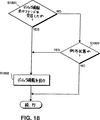
図18は、異なる契機となる条件の処理を示すフローチャートである。ステップS1801では、デバック情報出力のコマンドが受信されたかどうかを判断する。もし、受信があれば、処理はステップS1802に進む。もし、そのコマンドの受信がなければ、処理はステップS1803に進み、例外状態が検出されたかどうかを判断する。もし、例外状態が検出されたなら、処理はステップS1802に進む。そうでなければ、処理は終了し、他の処理が続行される。ステップS1802では、デバック情報出力ルーチンが実行される。即ち、ステップS1702〜S1705が実行され、それから、他の処理を続行する。
図18に示す処理に従えば、デバック情報を出力させる契機となる状態が受信されたときはいつでも、例外条件が検出されたときはいつでも、デバック情報が出力される。しかしながら、この処理はコマンド、或は/及び、例外状態を契機とする条件が利用できないように容易に変更可能である。ステップS1204に類似した処理が、ステップS1801とS1803各々の後に挿入され、上記いづれかの契機となる条件に応答してデバック情報を出力する前に時刻条件モードが設定されているかどうかを判断する。
さらにその上、契機となる条件各々を順次処理することは必ずしも必要ではない。その代わり、これらの条件がその処理を実行中の異なる場所で実行されるようにしても良く、図17のステップS1702〜S1705に示されているように、各々が独立に処理の契機となっても良い。例えば、1つのテストがCPSOCKETでなされ、デバック情報出力要求のようなコマンドがリモートワークステーションから受信されたかどうかを判断する。もし、これが発生したなら、フラグがセットされる。このフラグは、XPLが実行される中でステップS1801で検知される。これに対して、切断状態のような例外状態はMLIDのような別のソフトウェアモジュールによって監視される。もう一度、フラグがセットされる。このイベントはステップS1803で検知され、もし適切なら、またデバック情報が出力される。
従って、NEDがデバック情報のための画像形成ジョブを生成出力するようにさせる契機となる条件を設定したり処理することには大きな柔軟性がある。
図19は、図17に関して説明した処理についての変形例を示すフローチャートである。この変形例において、デバック情報源は、メモリに格納されたデータではなく、LAN100から受信される画像形成ジョブに関するデータである。
図19の処理ステップは、LANから受信したデバック情報をリフォーマッティングし、そのリフォーマットされたデバック情報をプリントする方法を図示している。図19に示す方法によれば、デバック情報はLANからバイナリコードとして受信されるが、NED1001でのリフォーマットモードを設定するコマンドがこれに先行する。リフォーマットモードでは、NED1001はデバック情報をリフォーマットし、バイナリコードをこれに相当する16進のACSIIキャラクタに変換する。リフォーマットされたデバック情報はその後、プリンタ102でのプリントのために出力される。
ステップS1901では、データをLAN100から受信する。ステップS1902では、デバックモード、即ち、データ変換モードがセットされているかどうかを判断する。このモードは、CPNETを用いてセットされる。例えば、CPNETはEPROM174に構成データを設定して、その後の全てのジョブに関してNED1001がデータ変換デバックモードになるようにする。また或は、NED1001が、その後の最初の画像形成ジョブだけについてデータ変換を実行するように構成することもできる。ステップS1902において、もし、データ変換モードが選択されるなら、処理はステップS1903に進む。そうでなければ、処理はその終了までスキップし、未変換データを画像形成装置に出力するといった他の処理を続行する。
ステップS1903では、上述のように、データはバイナリコードから対応する16進のASCIIコードに変換される。それから、処理はステップS1904に進み、デバック情報を構成する16進のASCIIキャラクタが出力される。このようにして、NED1001によってLAN100から受信した実際のデータが出力され、正しいデータが受信されているかどうか、プリンタが受信データに正しく応答しているかどうかが判断される。従って、NED1001によって受信データをフォーマットし出力することによって、NED1001に格納されたデータをフォーマットして出力することによってデバック情報が備えられるのと同様に、問題を分析診断する助けとなるデバック情報が備えられる。
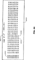
図20は、NED1001からの代表的なデバック情報がプリントされた1枚の用紙20100の例である。ヘッダ20010は16進表示(HEX)のダンプとしてのプリント出力であることを識別し、プリンタ102を識別するページヘッダである。欄20001は各行の最左端のバイトのメモリオフセットアドレスを示す。参照番号20002と20003とは夫々、16進データで、0DH、0AHを示し、これらは、キャリッジリターン命令と、ラインフィード命令とに対応ししている。そのデータはプリンタ102に送信されても、プリントされることはなく、その代わり、キャリッジリターン動作やラインフィード動作を引き起こす。しかしながら、プリンタ102への送信前に、バイナリデータが16進ASCIIキャラクタの“0”“D”と“0”“A”に変換されるので、格納された16進の値が0Dと0Aとして表示される。
もし、異なるフォーマットが望まれるなら、デバック情報に別のラベルを付したり、その配置の仕方を別のものに変えても良い。
[第2実施形態]
前述の実施形態に従えば、本発明は、NED1001が単方向インタフェースを介してNED1001と通信するので、プリンタ102に関して保持され出力される情報は限定されたものであった。ネットワーク機器によってロギングのために利用可能なプリンタ102に関する情報は、双方向周辺機器インタフェースを介してプリンタ102と通信を行うネットワーク機器を用いることよって、多くすることができる。そのようなネットワーク機器の例が、米国特許第5、323、393に説明されており、そこでは、双方向SCSIインタフェースをもつネットワーク機器と、双方向の共用メモリインタフェースを有したネットワーク機器を説明する“ネットワークプロトコルセンサ(Network Protocol Sensor)”という名称の米国特許出願第08/336,062号とについて説明している。
これに加えて、NEDのような外部的に装着されたネットワーク機器について、IEEE−1284パラレルインタフェースのような双方向パラレルインタフェースもまた、古典的なセントロニクスインタフェースの代わりに、周辺機器インタフェースとして利用できる。IEEE−1284インタフェースは、“パーソナルコンピュータ用双方向パラレル周辺機器インタフェースについての標準的信号処理方法(Standard Signalling Method For Bi-Directional Parallel Peripheral Interface For Personal Computers)”、IEEE−1284/D2、1993年9月版に説明されている。同様に、“赤外線データ協会:IrDAトランスポートプロトコルとしてISO8073の使用についての提案(Infrared Data Association: Proposal For The Use Of ISO 8073 As An IrDA Transport Protocol)”、ヒューレットパッカード、1994年4月22日版に説明されているようなIrDA(Infrared Data Accsociation)インタフェースが、周辺機器インタフェースとして利用できる。
双方向周辺機器インタフェースをもち、プリンタ102と共用メモリインタフェースをもつネットワーク機器という環境下で、第2実施形態を説明する。次の説明において、上述した構成要素と同等の要素については、同じ参照番号で参照することとする。
[ネットワークボード]
この実施形態において、本発明は、ハードウェア、ソフトウェア、及び、ファームウェアのソルーションを提供し、プリンタのようなネットワーク周辺機器を、ネットワークからデータを受信して処理するのみならず、詳細な状態情報と動作パラメータ等のような周辺機器についてのかなりの量のデータをネットワークに送信することが可能なインテリジェント対話型ネットワーク構成要素にするネットワークボード(NEB)に組み込まれる。また、ファクシミリ装置、コピー機、画像処理等のネットワーク周辺機器、特に、画像処理周辺機器のような他のネットワーク周辺機器において、本発明を用いることも可能である。周辺機器とともに、そのようなハードウェア、ソフトウェア、ファームウェアとをインテグレーションすることによって、パーソナルコンピュータを周辺機器サーバとして専従して動作させる必要性がなくなる。
図21は図1に示すNED1001の代わりにプリンタ102に結合されるネットワークボード(NEB)101に組み込まれた本発明を示すブロック図である。図21に示す他の構成要素は、図1に示す構成要素と構造及び機能の点で同一である。従って、この説明をここでは繰り返さない。
図22はNEB101をプリンタ102にインストールされた様子を示す破断斜視図である。図22に示されているように、NEB101は好適には、プリンタ102の内部拡張I/Oスロットに実装される。なお、プリンタ102は、本発明の好適な実施形態では、キャノン社製LBP1260レーザプリンタである。これによって、NEB101は以下に説明する処理とデータ格納についての特徴をもつ内蔵ネットワークノードになる。
NEB101のアーキテクチュアは、大規模なマルチエリアWANネットワークの管理運営についてのユニークな支援機能をもっているので、利点がある。これらの支援機能には、例えば、(ネットワーク管理者のオフィスからのような)ネットワーク上の離れた場所からのプリンタ制御と状態監視、ネットワークをまたがってアクセス可能である、プリンタの作業負荷を特徴づけまたトナーカートリッジ交換を計画するためのプリンタログ或は利用状況の統計が含まれている。
NED101の設計の重要な特徴は、双方向インタフェース、ここでは、共用メモリを介して、プリンタ102からプリンタ情報を受信する能力である。共用メモリインタフェースが用いられているが、SCSIインタフェース(例えば、米国特許第5,323,393号に開示されているように)のような他の双方向インタフェースもまた、NEB101とプリンタ102とのインタフェースとなるように用いることもできる。
上述のように、IEEE−1284のような双方向パラレルインタフェース、IrDAインタフェースをNEDに組み込むことも可能であり、その場合には、特に、プリンタ102からのデータ転送に関しては、NEDの機能性はNEB101と同等である。
上述した双方向インタフェースによって広範なプリンタ状態と制御情報とがNEB101に外部ネットワークノードに移出することが可能になり、従って、多くの有用な支援機能のプログラムが可能になる。例えば、NEB101の場合、プリント画像データと制御情報とのブロックとがNEB101上のマイクロプロセッサによって組み立てられ、共用メモリに書き込まれ、その後、プリンタ102によって読み出される。同様に、プリンタ状態情報はプリンタ102から共用メモリに転送され、そこからNEBのマイクロプロセッサによって読み出される。
プリンタ102からNEB101に送信されるプリンタ状態情報には、遷移状態、オンラインでプリント中、オフラインでプリント中ではない、エンジンテスト検出、保守プログラム実行中、スリープモードにある、用紙切れ、プリンタオープン、用紙詰まり、EPカートリッジなし、トナーが少ない、U−Lフィード、用紙積載、用紙供給、CaPSLオペレータコール、上部フィーダリジェクト、中間部フィーダリジェクト、下部フィーダリジェクト、上部にセット、中間部にセット、用紙流出、トレイがフル、ページフル、22ラインエラー、44ラインエラー、ダウンロードメモリがフル、作業メモリがフル、デッドロックメモリがフル、ジョブリジェクト、プリントチェック、フォントがフル、エンジンウォーミングアップ、外部オペレータコール、前面のカードが除去、NVRAMフル、ハードディスクがフル、メモリフル、低解像度なので低くできない、ハードティスクがクラッシュ、“電源切断せよ”、フルペイントリジェクト、スケールエラー、デュープレックスリジェクト、拡張I/Oエラー、トレイのトラブル、常駐ROMに悪いフォーマットあり、サポートされていないオプション、オプションフォントなし、メモリフルが回避不可能、サービスコールが起動中、立ち上がり状態、オフラインへ移行中、オンラインへ移行中、メニューでのオフラインでプリント中ではない、遷移状態にありメニューを終了してOFFLINEに戻る、パネルリセット要求、SWOFF検出(電源切断要求)、システムをリブート、パネルフォームフィード要求、パネルフォームフィードキャンセル、外部プログラムテストプリント、テストプリントキャンセル、保守プログラムが実行された等が含まれる。
図22に示されるように、ネットワークとの接続を可能にする前面プレート101bに装着されたプリント回路基板101aから構成されるNEB101はコネクタ170を介してプリンタインタフェースカード150に接続される。後述するように、プリンタインタフェースカード150は直接プリンタ102のプリンタエンジンを制御する。プリントデータとプリンタ状態コマンドとは、NEB101からコネクタ170を介してプリンタインタフェースカード150に供給され、プリンタ状態情報はコネクタ170を介してカード150から得られる。NEB101はこの情報を前面プレート101bのネットワークコネクタを介してLAN100に通信する。同時に、プリンタ102はまた、従来のシリアルポート102aとパラレルポート102bとからもプリントデータを受信できる。
図23は、NEB101のプリンタ102への電気的接続を示すブロック図である。NEB101は、LANインタフェースを介してLAN100に、また、プリンタインタフェースカード150を介してプリンタ102に直接接続される。本発明の好適な実施形態では、プリンタインタフェースカード150は、Peerless Systems Corp.から入手可能なPeerlessLBP−860/1260−外部標準I/Oボードインタフェースであり、その詳細は、Peerless標準I/Oインタフェース設計仕様、revision 2.07a、Peerless Systems Corp.1994年5月10日版にある。プリンタインタフェースカード150は、インテル社製80960KB−20マイクロプロセッサ151を含んでいる。それは、32ビットのマシンであるが、マイクロプロセッサ151はNEB101にまたNEB101からデータを2バイト幅(16ビット)でアクセスし、NEB101に配置された共用メモリ200を介して転送する。マイクロプロセッサ151はまた、実際にはプリント機構を駆動するプリントエンジン160と通信する。
[NEBの物理的レイアウト]
図24は、NEB101の好適な実施形態の大きさを示し、その主要な構成要素の物理的なレイアウトを示している。NEB101カードは、3.93インチ×5.60インチである。NEB101は、プリンタインタフェースカード150とLAN100への接続を可能にするコネクタ2301と2302とを有した前面プレート300とに接続されるプリントインタフェースカードコネクタ170(Peerlessプリンタインタフェースカードの場合、それは80ピンのコネクタである)を含んでいる。前面プレート300にはまた、4つの状態発行ダイオード(LED)303、2304〜2306が含まれている。また、NEBカードには、トランシーバ2171、水晶発振器2172、マイクロプロセッサ2173、動的ランダムアクセスメモリ(DRAM)2175、アービタ制御ロジック400、フラッシュ消去可能プログラム可能な読み出し専用メモリ(EPROM)2174、第1の静的ランダムアクセスメモリ(SRAM)2176、ネットワーク及びネットワークインタフェース制御ロジック2500、及び、シリアルポートコネクタ2600が備えられている。これらの構成要素各々については後で詳述する。
図25は、サイズが4.56インチ×1.28インチの前面プレート300の詳細を図示している。上述したように、NEB101はLAN100にコネクタ2301と2302を介して接続する。好適には、コネクタ2301は10Base−T接続が可能なRJ−45コネクタであり、一方、コネクタ2302は10Base−2接続が可能な単純な同軸(coax)コネクタでも良い。NEB101がデータをLAN100を介して送信中には状態LED303が点灯し、NEB101がLAN100からデータを受信中には状態LED2304が点灯する。状態LED2305はRJ−45コネクタがLAN100と接続されているときに点灯し、一方、状態LED2306はNEB101の自己診断テスト中に点灯する。マウント孔307はNEB101をプリンタ102に取り付けるためにスクリューを受容する。
[NEBアーキテクチュア]
NEB101のアーキテクチュアが図26に示されている。全ての回路に対する電力は、+5V電源2177からNEB101に供給される。+5V電源はまた、電力変換器178と179に供給される。電力変換器178は−9V電源をトランシーバ2171に与え、一方、電力変換器179は+12V電源を“フラッシング(即ち、EPROMの再プログラム化)”のためにフラッシュEPROM2174に供給する。
ネットワークとネットワークインタフェース制御ロジック2500は好適には単一の144ピンのアプリケーション専用集積回路(ASIC)であり、ネットワークコントローラ2510とインタフェース制御ロジック2520とを含んでいる。ネットワークコントローラ2510はナショナルDP83902A“ST−NIC”イーサネットコントローラと互換性のあるNCRマクロセルである。なお、ナショナルDP83902A“ST−NIC”イーサネットコントローラの詳細は、ナショナル半導体ローカルエリアネットデータハンドブック、ナショナルセミコンダクタp/n400055、ナショナルセミコンダクタ、1993年版に述べられている。ネットワークコントローラ2510は、CSMA/CD(Carrier Sense Multiple Access with Collision Detection)タイプのローカルエリアネットワークとインタフェースをもつために設計されている。
ネットワークコントローラ2510はRJ−45コネクタとは直接に、同軸コネクタ2302とは好適にはナショナル半導体製のDP8392同軸トランシーバインタフェースであるトランシーバ2171を介して接続されている。なお、そのトランシーバの詳細もまた、ナショナルのローカルエリアネットデータハンドブックに述べられている。ネットワークコントローラ2510はまた、イーサネットデータのために入出力パケットバッファとして用いられる8KBのSRAM176と結合されている。このメモリのアクセス時間は、約70nsec以下であることが好ましい。
インタフェース制御ロジック2520は、ネットワークコントローラ2510とマイクロプロセッサ2173とメモリデバイスEPROM2174と、DRAM2175との間のインタフェースを備える。また、インタフェース制御ロジック2520は、不揮発性ランダムアクセスメモリ(NVRAM)180とのインタフェースをもち、そのNVRAMはNEB101を内蔵するプリンタ102に電力が供給されている間、初期化データ格納のために用いられる256バイトの順次電気的消去/プログラム可能メモリである。ネットワーク及びプリンタ構成のパラメータは、プリンタが最初にネットワークにインストールされ、NEBソフトウェアがプリンタ電源のオフ/オン後にそのインストールパラメータを回復できるようになったとき、NVRAM180に書き込まれる。
インタフェース制御ロジック2520はまた、シリアルポートコネクタ2600に接続している。そのコネクタは、夫々にデバックのためにシリアルデータストリームを受信、送信できる受信データピン2601、送信データピン2602を有している。インタフェース制御ロジック2520は受信データラインに存在するデータを検知し、決まった間隔でそのシリアルビットをサンプルする。これについては後で詳細に述べる。
NEB101の中央コントローラはマイクロプロセッサ2173であり、好適にはインテル社製の8ビットプロセッサ80C188EA−20である。その詳細は、80C186EA/80188EAユーザーズマニュアル、インテル(Intel)p/n 270950-001、インテル社(Intel Corp.)に見ることができる。このプロセッサは、8ビットプロセッサであり、ダイレクトメモリアクセス(DMA)、インタラプト、タイマ、DRAMリフレッシュ制御の機能をもつ。AMD社製8ビットプロセッサ80C188−20のような他のマイクロプロセッサを代わりに使用することもできる。256KBのフラッシュEPROM2174と512KBのDRAM2175は、インタフェース制御ロジック2520を介してマイクロプロセッサ2173に結合され、一方、32KBのSRAM200(これはプリンタインタフェースカード150と共用される)はアービタ制御ロジック400を介してマイクロプロセッサ2173と結合される。40MHz、50ppmの水晶発振器2172はマイクロプロセッサ2173にクロック信号を供給する。このクロック信号は、プリンタインタフェースカード150のマイクロプロセッサ151に提供されるクロック信号とは完全に分離されており、非同期である。
マイクロプロセッサ2173は、制御ファームウェアとプリントアプリケーションソフトウェアを格納したフラッシュEPROM174にある命令を実行する。電源投入時の自己診断(POST)の後、コードは選択的により高性能の512KBDRAM2175に移動させられる。実際の実行のためには、DRAM175のアクセス時間は約80nsecであることが好ましい。フラッシュEPROM2174は、上述の発明の名称を“スマートフラッシュ”という米国特許出願第08/336,043号に説明されているように、LAN100から再プログラム可能、或は、“フラッシュ化”可能である。
NEB101のソフトウェアモジュールは、上述したNED1001のソフトウェアモジュールと同一であり、それはフラッシュEPROM2174に格納される。また、EPROM2174に格納されるものとして、NED1001のEPROM174に格納されたNIFデータブロックと同一のNIFデータブロックがある。従って、NED1001のEPROM174の内容を示す図8は、正確に、NEB102のEPROM2174の内容を図示している。この点について、NEB101とNED1001に格納されたソフトウェアモジュールとNIFデータブロックは同じであるので、上述したソフトウェアモジュールとNIFデータブロックの概略説明はここでは繰り返さない。
NEB101とプリンタインタフェースカード150との全ての通信は32KBの共用SRAM200を介して実行される。好適には、単一の100ピンのASICであるアービタ制御ロジック400は、プリンタインタフェースマイクロプロセッサ151の2バイト幅メモリアクセスとNEBマイクロプロセッサ2173の1バイト幅メモリアクセスとの間を調停する。ここで、マイクロプロセッサ151とマイクロプロセッサ2173とは各々互いに対して完全に独立である。
一般的に言って、NEB101にオンボードしたマイクロプロセッサ2173の8ビットデータバスはバス制御ロジック410と通信を行い、一方、プリンタインタフェースカード150にオンボードしたマイクロプロセッサ151の32ビットデータバスは、バス制御ロジック420と通信を行う。各々のバスからのメモリアクセスは共用メモリアービタ430を通るようにされ、そのアービタでは(後で説明するアービトレーション技術に従って)とのバスが優先権をもっているかを判断し、優先権をもっているバスがSRAMインタフェース440を介してSRAM200にアクセスできるようにする。インタラプト制御レジスタ450はまた、共用メモリアービタ430を介してアクセスされ、1つのマイクロプロセッサが他のマイクロプロセッサをインタラプトできるようにする。
[NEBの機能性]
広義に言えば、NEB101はプリンタ102をLAN100に結合し、プリンタ102を応答性に優れたインタラクティブなネットワークの構成要素とするインタラクティブネットワーク回路ボードである。NEB101はLAN100からプリントデータ、状態要求、及び、制御コマンドを受信し、プリント102にそのプリントデータ、状態要求、及び、制御コマンドを送信して実行させ、LAN100に状態情報を返信する。
従って、NEB101はRPRINTERリモートプリンタサービスとPSERVERプリントサーバ機能とを実行できるのみならず、ネットワーク構成要素に対して、周辺機器インタフェースから利用可能などんな状態制御機能も提供することができる。NEB101を介して、ネットワーク構成要素はNEBに格納された、例えば、プリントジョブ数、ジョブ当りのページ数、毎分のページ数、ジョブ当りの時間、一日当りの総ページ数、一日当りのジョブ数などの非常に多い状態情報にアクセスできる。これに加えて、例えば、ネットワークPCからプリンタのフロントパネルの機能を動作させて、非常に多くの制御情報もまた、ネットワークからプリンタ102に対して提供される。
全てのネットワークトラフィックは、トランシーバ2171を介してネットワークコントローラ2510とインタフェースをもつRJ−45コネクタ、或は、ネットワークコントローラ2510と直接インタフェースをもつBNCコネクタ2301を通ってNEB101に入ったり、NEB101を離れたりする。ユーザが物理的にスイッチの所にいるという必要をなくすために、NEB101は自動的に、2つのコネクタの内どちらがネットワークと接続されているのかを検出するハードウェアとソフトウェアとを含んでいる。このハードウェアとソフトウェアとは、“ネットワークプロトコルセンサ(Network Protocol Sensor)”という名称の米国特許出願第08/336,062号に開示されている。ネットワーク通信は、選択されたコネクタとボードの他の部分との間で、ネットワークコントローラ2510と選択されたコネクタのネットワークトラフィックとマイクロプロセッサ2173のデータバスとの間のデータの流れを制御するインタフェース制御ロジック2520とを用いて、転送される。
マイクロプロセッサ2173によって実行される全てのソフトウェアモジュールは、フラッシュEPROM2174に格納される。タイマによる印付けやNVRAM読み出しのようないつも必要となる下位レベルのモジュールは、EPROM2174から直接外に呼び出して実行される。しかしながら、大部分については、マイクロプロセッサ2173はフラッシュEPROM2174から直接にソフトウェアモジュールを実行することはせず、むしろ、選択的に必要となるモジュールをDRAM2175にロードして、DRAMから実行する。このような構成によって、フラッシュEPROM2174から取り出される特定のモジュールを選択し、DRAM2175で実行し、NEB101を柔軟に構成することが可能になる。
例えば、多くの通信プロトコルタイプはLAN100に広まるので、NEB101はフラッシュEPROM2174内に複数のプロトコルを支援するソフトウェアモジュールを含む。NEB101は、異種ネットワークの全てのネットワークトラフィックを監視して、使用中のプロトコルタイプ(1種或は複数種)を判断する。そして、検出したプロトコルに対応するプロトコルスタック(1種或は複数種)をDRAM2175にロードする。
新しいプロトコルスタックを含んでいるかもしれない新しいイメージでフラッシュEPROM2174を再プログラムすることはまた、DRAM2175を介して実行される。ネットワークやシリアルポートコネクタ2600を介して受信されるコマンドのような再プログラムするための新しいイメージと命令とが受信されると、ソフトウェア再プログラミングモジュールがEPROM2174からDRAM2175にロードされる。マイクロプロセッサ2173はDRAM2175からこのモジュールを実行し、その新しいファームウェアイメージがNEB101の構成と互換性があることを確認し、発明の名称を“スマートフラッシュ”という米国特許出願第08/336,043号に詳細に説明されているように、もし互換性が確認されるならEPROM2174を再プログラムする。
マイクロプロセッサ2173は、DRAM2175からロードされたプロトコルスタックを実行して、そのプロトコルを用いている他のLAN構成要素に対して或はその構成要素からネットワーク通信の送受信を行うことができる。プリントジョブデータはネットワークコントローラ2510によって受信され、インタフェース制御ロジック2520を介してマイクロプロセッサ2173に送られる。マイクロプロセッサ2173は、そのプリントジョブデータを共用メモリSRAM200に書込み、そのメモリからプリンタのマイクロプロセッサ151はデータを読み出し、そのデータに従ってプリンタエンジン160を動作させる。
上述したように、共用SRAM200へのアクセスは、アービトレーション優先権技術に従ってアービタ制御ロジック400によって調停される。アービタ制御ロジック400は、マイクロプロセッサの共用SRAM200へのアクセスをFCFS(first-come,first-served)方式に基づいて行なわせ、低い優先度のプロセッサに対しては待ち状態を呈示することによって、2つのマイクロプロセッサの同時的なアクセスを互いにインタリーブさせ、一方、高い優先度をもつプロセッサがアクセス順位を得るようにする。完全に同等な場合には、NEB101のマイクロプロセッサ2173に優先度が与えられるように調停される。
大部分の共用SRAM200はリングバッファとして構成され、NEBのマイクロプロセッサ2173はそのリングバッファにプリントデータを書込み、プリンタインタフェースのマイクロプロセッサ151をそのリングバッファからデータを読み出す。各プロセッサがブロックのデータを書き込んだり或は読み出したりするとき、そのプロセッサは夫々、SRAM200のどこかに格納されている“put”ポインタ或は“get”ポインタを更新し、プロセッサが次にアクセスすべき場所を示すようにする。
このような構成によって、“put”ポインタと“get”ポインタとを互いに比較することによって、書込みを行うプロセッサはメモリ内の書込みができる利用可能な空間があるかどうかを判断し、読み出しを行うプロセッサは読み出されるべきデータが残っているかどうかを判断する。2つのプロセッサ間の共用メモリの競合量を削減するために、NEBプロセッサ2173はメモリへの書込みを所定の間隔で停止し(従って、ポインタの読み出しと更新とを停止する)、プリンタインタフェースマイクロプロセッサ151だけが目的とするものを捉えるまでメモリにアクセスできるようにする。この点については後でもっと詳しく述べる。
シリアルポートコネクタ2600が設けられることによって、NEB101を外部コンピュータからデバックすることが可能になる。シリアルポートコネクタ2600はインタフェース制御ロジック2520に結合され、そのロジックはシリアルポートコネクタ2600の受信データピン2601からシリアルデータを受け、マイクロプロセッサ2173とそのシリアルデータをビット毎に通信する。マイクロプロセッサ2173はそのシリアルデータのスタートビットがマイクロプロセッサの非マスクインタラプトを起動するようにインタフェース制御ロジック2520を適合させる。それから、マイクロプロセッサ2173はシリアルデータのデータビットを8ビットワードに組み立てる。さらに、インタフェース制御ロジック2520は、マイクロプロセッサ2173のデータバスを監視し、そこに存在するデータのシリアルストリームを通過させ、そのデータをシリアルポートコネクタ2600のデータピン2602に送信する。
NVRAM180とフラッシュEPROM2174とはまたモデル番号、ファームウェアレベル、ボード改訂数のような“ボード”情報とともに、各ネットワークボートに対してユニークであるメディアアクセスコントロール(Media Access Control)(“MAC”)アドレス、ボード名、ネットワークフレームタイプ、プライマリファイルサーバ識別、サービスキュー、ネットワークプロトコル、サンプリング周波数、PSERVER名、ゾーン名等のような“ネットワーク”情報を格納する。
[NEBのアクセスと構成]
NED1001についての情報と同一であるNEB101についてのアクセス及び構成情報は、次のことのために保存する。NEB101はNED1001とは異なり、双方向周辺機器インタフェースを含んでいる。それゆえに、NEB101はネットワークに対して広範囲にわたる情報及び制御機能を備える能力を有している。上述したように、より具体的に言えば、大量の状態情報がプリンタ102からLAN100へと提供され、大量の制御情報がLAN100からプリンタ102へと提供される(例えば、プリンタに保持されたページカウントを取得したり、或は、PC103からオンライン/オフラインのようなプリンタのフロントパネルの機能を動作させて)。
従って、CPNETは、上述したように、NED1001の周辺機器インタフェースが単方向性であるという性質のために、NED1001では利用可能ではなかったプリンタからの情報にアクセスしたり、その情報を表示したりできる。そのような情報には、例えば、プリントジョブ当りのページ数が含まれる。
上述のように、NEB101のアクセス及び構成情報の残りは、NED1001での情報と同一である。従って、その説明についてここでは繰り返さない。
[自動ロギング機能]
NEB101は毎日午前零時にその時点の現在の状態と、プリンタ102の毎日の統計情報とをロギングする能力を含んでいる。これによって、ネットワーク管理者は、毎日のこのロギングを行うことを思い出す必要はなくなる。状態及び統計情報データは、例えば、NEBのDRAM2175、或は、NEBのNVRAM180に格納される。格納されるログファイルの場所と格納領域とは、各メモリの残存メモリ容量とネットワーク管理者によって選択されるロギングレベルによって必要とされる統計情報とに依存して、ネットワーク管理者によって選択される。もし、大容量のメモリ空間が利用可能であれば、ネットワーク管理者は、まさに詳細な“JOB”ロギングレベルを選択し、膨大な統計情報が維持される。これに対して、そのメモリ空間が制限されていれば、ネットワーク管理者は、それほど詳細ではない“ERROR”ロギングレベルを選択し、必要とされる記憶領域をより少なくできる。そのログファイルがいっぱいになれば、そのメモリの格納領域の周辺に新しいログデータは単純にくるんでおき、旧いログデータを新しいログデータで置換する。
ロギング機能は、第1実施形態において上述したNED1001について実行されたものと類似している。基本的な違いは、NEB101がプリンタとは双方向インタフェースをもっているが、NED1001はもっていないという事実からきている。従って、NEB101はNED1001と比較してより詳細な情報をプリンタから取得してログをとることができる。例えば、NEB101はプリンタの状態に関して、プリンタからまさしく詳細な情報を得ることができる。これに対して、NED1001は、オンライン状態とか用紙切れ状態といったプリンタ情報に関しては限定された情報しか得ることができない。そのログファイルで利用可能な異なる量の情報の他のものに関しては、ロギング機能の動作やログファイルやデバック情報の出力はNED1001についてもNEB101についても類似している。
図27は、CPSOCKETによってNEBで実行される処理の一部の概略を示すフローチャートである。ステップS2701では、LAN100から現在時刻が受信される。現在時刻受信後、処理はステップS2702に進み、いまが午前零時であるかどうか、即ち、戻ってくる時刻が新しい日付を示しているかどうかを判断する。
ステップS2702〜S2705は、プリンタ102からLAN100に、自動的にかつ体系的に状態情報を提供するために実行される所謂“自動ロギング”機能を含んでいる(自動ロギングについては後で詳細に説明する)。ステップS2702では、もし時刻が午前零時に達していないなら、その手順は他のタスクを続行する。しかしながら、時刻が午前零時に達すると、ステップS2703で、NEBのマイクロプロセッサ2173はプリンタ102に対してプリンタ102がNEB102に対して現在の状態を返答するように要求を送信する。例えば、プリンタ102は、累積されたプリントページ数をNEB101に返答するかもしれない。ステップS2704において、NEBのマイクロプロセッサ2173は、一日当りのジョブ数や一日当りのページ数のようなプリンタ統計を計算し、NEB101はプリンタに送られるジョブ数とその日付を追跡し続ける。ステップS2705において、そのプリンタ統計情報は、NEBのNVRAM180のような不揮発性メモリに転送される。あるいは、ステップS2703、S2704、S2705をステップS2702の前に実行し、統計情報が毎分格納されるようにしても良い。
ステップS2702〜S2705について要約すると、双方向インタフェースを介してLAN通信のためにインタラクティブネットワークボードに接続されるプリンタのシステム統計情報をロギングする方法には、プリンタ102でプリントされるページ数をカウントし、ボードでプリントジョブ数をカウントすることを含む。プリンタは毎日双方向インタフェースを介して、プリントページ数について調べられ、ボードはその後、そのページ数、ジョブ数、他の情報を用いて、毎日の統計情報を計算する。その毎日の統計情報は格納され、CPNETを用いて、PC103のようなネットワーク管理者のPCからアクセスされ、リモートに表示される。上述のように、“自動ロギング”の機能の付加的な特徴は、異なるレベルの統計情報がログされるということである。例えば、基本レベルでは、ジョブ当りのページ数のような統計情報がログされる。さらに高いレベルでは、統計情報とエラー情報とがログされる。そのような高いレベルでは、ジョブ当りのページ数に加えて、失敗条件のログをログしても良いし、或は、失敗条件やジョブ当りのページ数に加えて、ジョブ開始終了時刻をログしても良い。そのロギングレベルはCPNETによって設定される。
CPNETの使用時、ネットワーク管理者に利用可能な1つのオプションは、表示履歴情報オプションを選択するオプションである。そのオプションによって、ネットワーク管理者はNEB101がコンパイルする一群のジョブ関連統計情報を表示することが可能になる。その表示される統計情報には、ジョブ平均、頁平均、性能データを含む。統計情報に加えて、CPNETによって構成されるように、NEB101は各プリントジョブについてのログを創成し、そのログをワークステーションディスクに書き込んだり、そのログを消去したりできる。ネットワーク管理者はまた、その統計情報を初期化するオプションを選択できる。
もし、ネットワーク管理者が表示オプションを選択するなら、CPNETは、LANインタフェースを介して、対象とするNEBにログファイルLAN要求を指示する。NEB101において、CPSOCKETはその要求を受信し、どこに格納されていてもログファイルを取り出し、LANインタフェースを介してネットワークにそのファイルを提供し、CPNETで受信されるようにする。
そのログファイルには、3つのカテゴリ、即ち、日毎、累積、平均、に分割された統計情報についての値が含まれる。“日毎”は現在の日の値を示す。“累積”は最後にリセットされてからの全ての日、或は、ディスクドライブのないプリンタの電源投入されてからの全ての日についてのトータルを示す。“平均”は、累積トータルを最後にリセットされてからの全ての日で割ったものである。これら3つのカテゴリ各々について(CPNETがロギングレベルを“NONE”に設定していないなら)、NEB101は次の値についてのトータル値を保持する。即ち、日数(リセットされて以来の日数、或は、電源投入されて以来の日数)、プリントされたページ数、処理されたプリントジョブ数、オフライン時間、ジョブ情報、エラー情報、及び、プリント時間である。
CPNETはまた、格納されたログファイルを取り出し、画面上に表示して見れるようにしたり、或は、プリントしたりする。そのログファイルは、逆日付順となっており、次のレコードタイプを含んでいる。そのログファイルの正確な内容は表2に要約されているように、CPNETによって設定されたロギングレベルに従って変化する。なお、そのログファイルへの各エントリには、エントリの日付と時間が付される。
上述のように、ネットワーク管理者は、4つのロギングレベル、つまり、NONE、AUTO、ERROR、JOBを選択可能である。NONEレベルでは、ロギング統計情報は保持されない(しかし、その情報は毎分計算され、一時的にNEBのDRAM2175に保存されることもある)。AUTOレベルでは、プリント日付、ページ、ジョブ、オフライン時間、プリント時間のようなプリンタの主要な情報についての日毎の統計情報が保持される。プリント累積ページ数はプリンタによって決定されるが、他の統計情報はNEBによって決定される。
ERROR(エラー)ロギングレベルは、上述したような日毎の統計情報と、また、プリンタ102のエラー状態と、アプリケーション(即ち、CPSERVER)で発生するエラーとを保持する。NEB101はプリンタ102にそのようなエラー状態について問い合わせ、それらが発生したときそのエラー状態をログする。そのようなプリンタエラー状態には、オフライン、用紙切れ、プリンタがオープン、用紙詰まり、トナーカートリッジがない、トナーが少ない、プリンタフィード及びロードエラー、トレイが満載、ラインエラー、プリントジョブリジェクト、フォントフル、サービスコール等が含まれる。アプリケーションエラーには、ファイルサーバダウン、プライマリサーバ利用不可、CPSERVERが他の場所で実行中、プリントキューが見つからない等が含まれる。
JOB(ジョブ)ロギングレベルには上述の日毎の統計情報とエラー状態とを保持し、またさらに、NEB101で判断されるジョブ開始と終了の情報とを保持する。もちろん、ロギングレベルの数と種類や、各ロギングレベルで保持されるデータはNEB101がインストールされる固有の周辺機器や固有のLANに応じて変化する。
図28A及び図28Bは、NEB101内の自動ロギング機能の動作概要を示すフローチャートを含んでいる。ここでは、図27や上述した表2を参照する。ステップS2801では、NEB101に電源が投入され、ステップS2802ではタイマモジュールが最も近接したサーバを見つけ、時刻を要求する。ステップS2803では、NONEロギングレベルが選択されているかどうかを判断する。もし、NONEロギングレベルが選択されているなら、処理はそのフローチャートの終了にスキップし、メイン処理に戻る。
もし、NONEロギングレベルがステップS2803で選択されていないなら、ステップS2804ではAUTOロギングレベルが選択されているかどうかを判断する。AUTOロギングレベルが選択されているなら、処理はステップS2810に進み、午前零時まで待機する。しかしながら、AUTOロギングレベルが選択されていないなら、ステップS2805ではERRORロギングレベルが選択されているかどうかを判断する。そこで、ERRORロギングレベルが選択されているなら、処理はステップS2808にスキップし、1分のタイムアウトまで待機する。しかしながら、ERRORロギングレベルが選択されていないなら、ステップS2806で、JOBロギングレベルが選択されていると判断する。この場合、ステップS2807はジョブの開始及び終了時刻をログファイルに格納する。ステップS2808では、1分間が経過するのを待ち合わせ、それから、ステップS2809で、プリンタにエラー状態を問い合わせ、そのようなイベントをログファイルに格納する。従って、ERROR或はJOBロギングレベルが選択されたなら、そのボードはプリンタにエラー状態について問い合わせ、それが発生したときに、ログファイルにそのようなエラー状態を記録することになる。
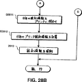
ステップS2810では午前零時を待ち合わせ、ステップS2810(図28B)では、その時刻にNEB101はプリンタに日毎の統計情報を問い合わせる。ステップS2810において、午前零時に達していないなら、その手順はステップS2804に戻り、どのロギングレベルが選択されているかを判断する。
ステップS2812では、ステップS2811で受信したプリンタ統計情報を用いて、日毎のプリンタ統計情報が計算される。その後、ステップS2813では、日毎の統計情報とそのエラーイベントとがNEBのNVRAM180に格納される。なお、ネットワーク管理者は、いくつかのメモリを組み合わせて、ロギング統計情報とエラーイベントとを格納するように選択し、LAN100にいっそうの柔軟性を備えるようにできる。
上述した、ロギング機能はプリンタ102をLAN100のインタラクティブな応答性のある構成機器とするためにかなり重要である。なぜなら、NEB101とプリンタ102との間の共用メモリ接続によって、プリンタ102から大量の特定データを抽出できるからである。
上述のように、NEB101は、プリンタ102と、SCSIインタフェースのような異なる種類の双方向インタフェースを用いるようにしても良い。例えば、上述した“ネットワーク周辺機器の状態を取得し制御する方法及び装置(Method And Apparatus For Obtaining And For Controlling The Status Of A Networked Peripheral)”という名称の米国特許第5,323,393号に説明されているNEBには、SCSIインタフェースが用いられている。そこで説明されているNEBは、プリンタとNEBとの通信により、大きな柔軟性を備えている。例えば、オプションとして、ログファイルが、NEBのメモリへと同様にプリンタのハードディスクにも格納される。もし、プリンタがハードディスクをもっているなら、ネットワーク管理者はまさしく詳細な“JOB”ロギングレベルを選択し、大量の統計情報を保持できる。これに対して、プリンタにハードディスクがないなら、ネットワーク管理者は、それほど詳細ではない“ERROR”ロギングレベルを選択して、必要とされる記憶空間をより少なくできる。
[ログファイル出力]
図11は、自動ロギング機能によって生成されたログファイルをNEB101から出力する処理を示すフローチャートである。そのログファイルには、選択されたロギングレベルに依存して、NEB101とプリンタ102との動きに関連した情報が含まれる。なお、その情報量は変化する。上述のように、ログされる情報量は、NEB101に利用可能なプリンタ102についての情報量に依存する。
図11の処理ステップでは、ローカルエリアネットワーク(LAN)と画像形成装置との間でインタフェースとなるネットワーク機器からのログファイルを出力する方法を図示している。保持されるログファイルは、LANから受信する画像形成ジョブとその画像形成装置への出力とを記録する。ログファイルの出力を開始する契機となる条件を検出すると、そのログファイルは画像形成ジョブへとフォーマットされ、そのフォーマットされたログファイルが画像形成装置に出力される。
上述のように、図11に示される処理はマイクロプロセッサ2173で実行しているCPSOCKETプログラムのセクション或はサブタスクにインプリメントされている。ステップS1101では、契機となる条件が検出されたかどうかを判断する。ログファイルの出力の契機となるために用いられる条件の例は、NED1001について上述されている。これらの契機となる条件がNEB101にも適用される。従って、その点についてはここで繰り返して説明しない。
契機となる条件が検出されたなら、処理はステップS1102に進む。そうでなければ、処理は終了までスキップし、他の処理を続行する。ステップS1102では、ログファイルが取り出され、画像形成ジョブにフォーマットされる。このフォーマッティングは好適には、ページヘッダの追加、ロギングファイルデータをフォーマットしてプリントページを形式的に整えること、フォームフィードのような制御キャラクタをデータストリームに追加することのような動作を含むと良い。そのディフォルトモードでは、フォーマットされたログファイルデータが、大抵の画像形成装置を駆動している普通のACSIIキャラクタフォーマットとなる。もし、特定の画像形成装置がPostScriptフォーマットのような異なるフォーマットでのデータを要求することが知られているなら、NEB101はそのログファイルを適切なフォーマットへとフォーマット化するように構成できる。この構成は、例えば、CPNETを用いて実現される。その上、NEB101は装着された周辺機器と双方向インタフェースをもつので、その周辺機器によって必要とされるデータフォーマットを判断するために周辺機器に問い合わせをすることができる。
NED1001に関連して上述した図11の残りの処理ステップは、NEB101からログファイルを出力するステップと同一である。従って、その説明についてはここでは繰り返さない。
NED1001に関して、図12に従って異なる契機となる条件の処理が上述されているが、この処理はNEB101でも全く同じように実行される。従って、その詳細な説明はここでは繰り返さない。
図29は、ロギングのAUTOレベルが設定されプリンタ102に出力されるときNEB101のログファイルに格納されるプリント出力データの出力例である1枚の用紙29100である。図29は図13(NED1001に格納されたプリント出力データの出力例を示す)とは、図29がNED1001の単方向周辺機器インタフェースを介してNED1001に送信できないプリンタ情報を含んでいるという点で異なる。
図29において、ヘッダ29010はそのプリント出力がログファイルであることを識別し、プリンタ102の名前を識別する。欄2901は日付を示し、欄2902は時刻を示す。欄2903はレコードタイプを示し、それは表2に示したレコードタイプに対応する。欄2904〜2908は各々、日数、ページ数(プリンタ102から受信する)、ジョブ数、プリンタ102がオフラインである時分数、プリンタ102がプリントしている時分数を示す。
その記録は逆時間順である。従って、そのファイルの最近の記録は生成されたものの第1レコードであり、それは電源投入の記録2907(タイプ POW、表2参照)である。POWレコードのデータは次の通りである。
E=Ethernet(イーサネット)
1.39=ファームウェアのバージョン
00680B=MAC(Media Access Controlメディアアクセスコントロール)アドレスの最後の数字
CMQA_LAB−A=プリンタ名
上述のように、ログファイルの内容は、選択されたロギングレベルに依存する。更にその上、異なるフォーマッティング或は/及びラベルが必要に応じて用いられることもある。
[テストページ生成]
図14はNEB101がどのようにしてNEB101がインストールされたプリンタ102の状態変化、特に、フロントパネル1021を通してなされる状態変化に基づいてテストページ情報を生成出力することができるのかを図示したフローチャートである。テストページ情報はボード情報とネットワーク情報との少なくとも1つを含み、周辺機器のフロントパネルを操作してその周辺機器の状態を変化させることによって生成される。NEB101はLANにLANインタフェースによって接続され、周辺機器に周辺機器インタフェースによって接続される。LANインタフェースはネットワーク情報のために監視され、周辺機器のフロントパネルは所定時間にわたり所定の回数だけ操作されてその周辺機器で所定の順番で状態の変化を発生させる。その所定の順番での状態変化は周辺機器インタフェースを介してネットワーク機器と通信され、その所定の順番での状態変化に応答して、ネットワーク機器は、ボード情報とネットワーク情報との少なくとも1つを含むテストページ情報を生成する。そのテストページ情報は、周辺機器インタフェースを介して周辺機器と交信され、その周辺機器に出力される。
より具体的には、ステップS1401で開始するが、マイクロプロセッサ2173は、図23に示す共用RAMやSCSIインタフェース等の双方向周辺機器インタフェースを介して、周辺機器状態データを受信する。この場合、双方向周辺機器インタフェースは共用RAMである。周辺機器状態データは、通常、状態変化を検出したときにはいつでも、その状態データを更新するプリンタインタフェースカード150から受信される。或は、その代わりに、NEB101がカード150からの状態データの伝送を要求することもできる。その受信した周辺機器状態データに基づいて、マイクロプロセッサ2173は周辺機器の状態の変化が発生したかどうかを判断する。
マイクロプロセッサ2173は、共用RAM200(或は、どんな双方向インタフェースでもよいが)を介して送信されるどんな状態変化でも、初期の状態変化として、解釈するように設定されていても良い。しかしながら、本発明の好適な実施形態では、初期の状態変化は図2Bに示すフロントパネル1021の操作によって引き起こされる。具体的には、ユーザはプリンタ102のフロントパネルの“オンライン/オフライン”機能ボタンを押下することによりプリンタ102での初期の状態変化を生じさせる。しかしながら、既に示唆しているように、その初期の状態変化は、双方向周辺機器を介して送信されるどんな状態変化によっても生じさせることができる。
一旦、マイクロプロセッサ2173がステップS1401においてプリンタ102の初期の状態変化を検出すると、処理はステップS1402へ、それからステップS1403へと進む。これら2つのステップの説明は、NED1001についての2つのステップの説明と同一である。従って、その説明はここでは省略する。
ステップS1404では、マイクロプロセッサ2173はXPLモジュールにあるテストページモジュールを実行する。図15は、XPLモジュールのテストページモジュールが構成され、“ネットワーク”情報と“ボード”情報のみを含むテストページ情報を生成する処理を示すフローチャートである。ステップS1501では、テストページモジュールは、テストページについてのデータをメモリから読み出す。NEB101の場合、NED1001とは異なり、情報はEPROM2147とNVRAM180とから読み出される。そのテストページについての情報は、モデル番号、ファームウェアレベル、ボード改訂数のような“ボード”情報とともに、MACアドレス、ボード名、ネットワークフレームタイプ、プライマリファイルサーバ識別、サービスされるキュー、ネットワークプロトコル、サンプリング周波数、PSERVER名、ゾーン名等のような“ネットワーク”情報を含んでいる。なお、これら全ては既に示唆されているように、EPROM2174とNVRAM180に格納されている。同様に、テストページモジュールは、“ネットワーク情報”という範疇の下に、“ネットワーク接続なし”という情報を含めることができる。上述したように、マイクロプロセッサ2173はLANインタフェースを監視し、この情報を得る。前述の情報のどれがテストページを生成するために用いられるかは、まさしく、XPLモジュールのテストページモジュールに設定される。
上述のように、ステップS1502では、テストページモジュールはステップS1501で読み出されたテストページ情報をフォーマットする。本発明の好適な実施形態では、そのテストページ情報は図16に示すように、フォーマットされる。その詳細な説明は、NED1001に関して、既になされている。
同様に、NED1001に関して上述されているように、テストページフォーマットはXPLモジュール内のテストページモジュールに設定でき、付加的な情報をテストページに含むようにできる。
テストページ情報が生成された後、処理は図14のステップS1405に戻り、テストページ情報は共用RAM200を介してプリンタ102に送信される。ステップS1406では、プリンタ102はテストページとして、NEB101から受信したテストページ情報をプリント出力する。
上述の場合のように、図示はされていないが、テストページ情報はLAN100に出力できる。この場合、テストページ情報はファイルサーバ106に格納され、ネットワーク上の他のPCがプリンタ102についてのテストページ情報にアクセスできる。
上述したように、上記の説明は、テストページ情報が“ボード”情報と“ネットワーク”情報とだけを含むNEB101の実施形態に適用される。しかしながら、共用RAM200(或はSCSIインタフェース)は双方向のインタフェースであるので、プリンタ情報は、NEB101によって生成出力されるテストページ情報にも含まれる。
プリンタ情報をテストページ情報に含ませるために、NEB101のXPLモジュールのテストページモジュールがプリンタ102に対して必要とするプリント情報を問い合わせ、これをプリンタ102から受信するために実行される。図30は、この場合のテストページモジュールの動作を示すフローチャートを示している。一旦、プリンタ情報が取得されたなら、図14はまさしく、NEB101によって生成出力されるテストページ情報(プリンタ情報を含む)の処理を説明することになる。
ステップS3001では、テストページモジュールは共用RAM200(或はSCSIインタフェース)を介してプリンタ102からの所定のプリンタ情報を要求する。この所定のプリンタ情報とは、テストページ出力の中に含まれることになる情報である。そのテストページモジュールは、望むなら、プリントページ数やフォント登録等のような共用RAM200(或はSCSIインタフェース)を介して送信されるどんな利用可能なプリンタ情報についても要求するように設定できる。
テストページに含むことができるプリンタ状態情報のより完全なリストには以下のものが含まれる。即ち、遷移状態、オンラインでプリント中、オフラインでプリント中ではない、エンジンテスト検出、保守プログラム実行中、スリープモードにある、用紙切れ、プリンタオープン、用紙詰まり、EPカートリッジなし、トナーが少ない、U−Lフィード、用紙積載、用紙供給、CaPSLオペレータコール、上部フィーダリジェクト、中間部フィーダリジェクト、下部フィーダリジェクト、上部にセット、中間部にセット、用紙流出、トレイがフル、ページフル、22ラインエラー、44ラインエラー、ダウンロードメモリがフル、作業メモリがフル、デッドロックメモリがフル、ジョブリジェクト、プリントチェック、フォントがフル、エンジンウォーミングアップ、外部オペレータコール、前面のカードが除去、NVRAMフル、ハードディスクがフル、メモリフル、低解像度なので低くできない、ハードディスクがクラッシュ、“電源切断せよ”、フルペイントリジェクト、スケールエラー、デュープレックスリジェクト、拡張I/Oエラー、トレイのトラブル、常駐ROMに悪いフォーマットあり、サポートされていないオプション、オプションフォントなし、メモリフルが回避不可能、サービスコールが起動中、立ち上がり状態、オフラインへ移行中、オンラインへ移行中、メニューでのオフラインでプリント中ではない、遷移状態にありメニューを終了してOFFLINEに戻る、パネルリセット要求、SWOFF検出(電源切断要求)、システムをリブート、パネルフォームフィード要求、パネルフォームフィードキャンセル、外部プログラムテストプリント、テストプリントキャンセル、及び、保守プログラムが実行完了である。
テストモジュールは、ステップS3002で、プリンタ102から要求したプリンタ状態情報を受信し、ステップS3003ではEPROM2174とNVRAM180から“ボード”及び“ネットワーク”情報を読み出す。ステップS3004では、テストページモジュールはそのプリンタ情報と“ボード”情報と“ネットワーク”情報とをテストページ情報とに結合し、上述のようにそのテストページ情報をフォーマット化する。一旦、そのテストページ情報がフォーマットされたなら、処理は図14に示されているように進行する。
[フォーマットされたデバックデータ出力]
図17はフォーマットされたデバック情報をNEB101から出力する処理を示すフローチャートである。このデバック情報は画像形成機器が正しく動作していないときに問題の原因を判断するために有用である。特に、デバック情報は問題がネットワークボードの構成や動作にあるのか或は画像形成機器にあるのかを判断するために助けになる。一般的に言って、デバック情報はNEB101のメモリ内容のダンプである。出力されるデバック情報は、例えば、ネットワークボードの構成に関連したEPROM2174とNVRAM180の内容と、LAN100からの画像形成ジョブの受信と接続された画像形成機器への画像形成ジョブの出力におけるネットワークボードの動作に関連したDRAM2175の内容とを含んでいる。この情報はまた、衝突の回数と送受信のパケットの数のようなネットワーク統計情報とを含んでいる。
図17の処理ステップは、ローカルエリアネットワーク(LAN)とプリンタ102のような画像形成装置との間でインタフェースとなるネットワーク機器からのフォーマットされたデバック情報を出力する方法を図示している。デバック情報は、LANからの画像形成ジョブ受信時と、画像形成装置への画像形成ジョブの出力時に、ネットワーク機器の動作に関連したネットワーク機器に格納される。デバック情報の出力を開始させる契機となる条件を検出すると、そのデバック情報は画像形成ジョブにフォーマットされ、そのフォーマットされたデバック情報は画像形成装置に出力される。
上述のように、図17の処理は、マイクロプロセッサ173で実行されるCPSOCKETプログラムのセクション或はサブタスクによって実行される。NED1001に関して上述した図17に従う処理は、NEB101に関する処理と同一である。従って、その詳細な説明はここでは行なわない。
図17において上述した処理によって、デバック情報についての画像形成ジョブがNEB101で生成されるので、その結果、そのデバック情報は、コンピュータがNEB101にアクセスする必要なしに、NEB101に装着された機器を通してアクセスされる。この機能は、例えば、プリンタ、複写機、或は、ファクシミリのような画像を形成することが可能な機器に接続されるどのNEDについても選択される。
デバック情報出力機能は、種々の条件が出力を開始する契機となる状態として選択されるようにすることで、柔軟性をもたせている。選択された契機となる条件は、CPNETを用いて構成され、NEB101に格納される。NEB101で用いられる可能性のある契機となる条件は、NED1001に関して上述したものと同一である。従って、その詳細な説明はここでは繰り返さない。
NED1001に関して上述したように、図18もまた上述したように、異なる契機となる条件の処理を示すフローチャートを示している。NED1001についての図18の説明は同様にNEB101にも適用するので、その詳細な説明はここでは繰り返さない。
図19は、図17に関して説明した処理についての変形例を示すフローチャートである。この変形例において、デバック情報源は、NEB101のメモリに格納されたデータではなく、LAN100から受信される画像形成ジョブに関するデータである。
図19の処理ステップは、LANから受信したデバック情報をリフォーマッティングし、そのリフォーマットされたデバック情報をプリントする方法を図示している。図19に示す方法によれば、デバック情報はLANから受信されるが、NEB101でのリフォーマットモードを設定するコマンドがこれに先行する。リフォーマットモードでは、NEB101はデバック情報をリフォーマットし、バイナリコードをこれに相当する16進のACSIIキャラクタに変換する。リフォーマットされたデバック情報はその後、プリンタ102でのプリントのために出力される。
ステップS1901では、データをLAN100から受信する。ステップS1902では、デバックモード、即ち、データ変換モードがセットされているかどうかを判断する。このモードは、CPNETを用いてセットされる。例えば、CPNETはNVRAM180に構成データを設定して、その後の全てのジョブに関してNEB101がデータ変換デバックモードになるようにする。このことはCPNETがフラッシュEPROM2174に構成データをセットするという点でNED1001とは異なる。また或は、NEB101が、その後の最初の画像形成ジョブだけについてデータ変換を実行するように構成することもできる。ステップS1902において、もし、データ変換モードが選択されるなら、処理はステップS1903に進む。そうでなければ、処理はその終了までスキップし、プリントアプリケーションは他の処理を続行する。
ステップS1903からは、処理はNED1001に関連して上述したものと同一である。従って、その詳細な説明はここでは繰り返さない。
図20は、NED1001に関して既に上述したが、この図はNEB101からのデバック情報のプリント出力がどのようなものかを例示している。これは、NED1001に関するものと同一である。図20は上述したので、その詳細な説明はここでは繰り返さない。
もし、異なるフォーマットが望まれるなら、デバック情報に別のラベルを付したり、その配置の仕方を別のものに変えても良い。
本発明の実施形態について説明したが、本発明は上述した実施形態に限定されるものではなく、本発明の概念や範囲を逸脱することなく、種々の変更や変形が当業者にとっては可能である。 Background of the Invention
Field of Invention
The present invention provides an interface between a peripheral device and a network, receives peripheral device status data from the peripheral device, and includes network information and / or network device information in response to the status data (including printer information). Good) relates to a network device that generates and outputs a test page.
Incorporation by reference
US Pat. No. 5,323,393, “Method and apparatus for obtaining and controlling the status of network peripherals”, US patent application Ser. No. 08 / 336,062, “Network protocol sensor”, and US patent application Ser. No. 08/336. No. 043, “Smart Flash” is hereby incorporated herein by reference.
Explanation of related technology
Currently available printers often have a front panel with buttons that can be operated by the user. Among these buttons, there is a button for generating and printing a page including the printer status and analysis information.
Such a printer can be connected to a computerized local area network (LAN) using a network expansion board, which is described in US Pat. No. 5,323,393. However, test page information about the network cannot be generated and printed via the board (as opposed to the printer) or the front panel. Rather, such information is accessed and printed only from a PC (personal computer) on the network. However, this method of printing network and network interface information is inconvenient. This is especially true when the network peripheral is physically far from the network PC.
A special printer such as the DEClasar 5100 <R> can print out a test page including network information by operating a button on the front panel of the printer. However, these printers have special “Network Test Page” function buttons that are not found in conventional printers, but which do not go beyond peripheral devices such as facsimile machines and copiers. Furthermore, printers such as DEClasar 5100® have special network interfaces that are not compatible with other printers as well as other peripheral devices. Therefore, the general problems associated with printing network information and network interface information via the front panel of conventional network peripherals are not related to these special printers.
Accordingly, an interface board serving as an interface between a LAN and a conventional network peripheral device, and network information and information related to the interface board can be printed via the front panel of the network peripheral device. There is a need for a board.
Summary of invention
The above-described necessity is an interface between a conventional network peripheral device and a LAN, and a network that generates and outputs test page information including network information and network interface information in response to a change in state in a predetermined order in the peripheral device. It is handled by the present invention as a device. In response to a change in state of the peripheral device in a predetermined order, the network device generates and outputs test page information, so that the test page information is displayed on the front panel of the peripheral device to change the state of the network peripheral device. By operating the function button, it can be generated and output in a conventional network peripheral device.
One feature of the present invention is an interactive network device serving as an interface between a peripheral device and a network including a front panel provided so that a user can participate in the state of the peripheral device. The interactive network device is an interface with the network, a network interface for communicating peripheral device data via the network, and an interface with the peripheral device, and communicates the peripheral device with the peripheral device data, Peripheral device interface for receiving the status of the peripheral device from the peripheral device, and analyzing the status of the peripheral device received by the peripheral device interface to generate a predetermined in the peripheral device generated through the front panel A test that detects a plurality of state changes in order and, in response to detecting the plurality of state changes in the predetermined order, includes (a) at least one of network information and information of the interactive network device; Generating page information, (b) Characterized by a processor for controlling to output a test page information.
Since the above-described interactive network device generates and outputs test page information in response to a change in state in a predetermined order with respect to the peripheral device, the network information and / or the network is transmitted from the interactive network device via the front panel of the peripheral device. Interface information can be printed.
Another feature of the present invention is an interactive network device that provides an interface between a network and a printer, generates a test page, and outputs the test page via a printer interface so that the test page is printed out by the printer. It is. This device serves as an interface with the network, receives a print job, and serves as an interface with the printer. A printer interface through which the print job is transmitted and printer status data is received, and the network interface. A print buffer for storing the print job received via the memory, a memory for storing a plurality of software modules, at least one of which is a print server module, and (a) executing the print server module and storing it in the print buffer Transmitting at least one print job to the printer via the printer interface, and (b) analyzing the status data received via the printer interface; It is determined whether or not the printer status indicated by the status data has changed a predetermined number of times within a predetermined time in accordance with an operation on the front panel of the printer, and (c) the printer status indicated by the status data is determined on the front panel. A test page including at least one of the interactive network device information and the network information is generated when the predetermined number of times changes within a predetermined time in accordance with the operation of (d), and (d) the printer via the printer interface And a processor for controlling to output the test page.
With the above-described features, it is possible to print out a test page to a printer by operating a function button on the front panel of the printer in which the network expansion device is installed.
According to another feature, the present invention is connected to a network by a network interface, and at least one of the network device information and the network information from a network device connected to the peripheral device by a peripheral device interface. Is an information output method for outputting test page information including two. The method includes a step of changing a state of a peripheral device in a predetermined order by operating a button on a front panel of the peripheral device a predetermined number of times within a predetermined time, and the network device and the network device via the peripheral device interface. Communicating status changes in a predetermined order with peripheral devices; and in the network device, in response to the status changes in the predetermined order, the network device information and the network information A step of generating test page information including at least one of: a step of communicating the test page information between the peripheral device and the network device via the peripheral device interface; and And a step of outputting test page information.
According to still another feature, the present invention is connected to a network by a network interface, and at least one of the network device information and the network information is obtained from a network device connected to the peripheral device by a peripheral device interface. This is an information output method for outputting test page information including the information. In the network device, the state of the peripheral device received by the peripheral device interface is analyzed in the network device, and a plurality of state changes in a predetermined order in the peripheral device are generated via the front panel of the peripheral device. Detecting in the network device, generating test page information including at least one of the network device information and the network information, and in the network device, And outputting the test page information to the peripheral device via the peripheral device interface in response to detection of the state change.
According to still another feature, the present invention is connected to a network by a network interface, and at least one of the network device information and the network information is obtained from a network device connected to the peripheral device by a peripheral device interface. This is an information output method for outputting test page information including the information. In the network device, the state of the peripheral device received by the peripheral device interface is analyzed in the network device, and the state of the peripheral device changes a predetermined number of times within a predetermined time according to an operation on the front panel of the peripheral device. Detecting in the network device, generating in the network device test page information including at least one of the network device information and the network information, and in the network device, the status of the peripheral device. Outputting the test page information to the peripheral device via the peripheral device interface in response to detecting that the predetermined number of times has changed within the predetermined time in accordance with an operation on the front panel. It is characterized by that.
According to still another aspect, the present invention is a network board that interfaces between a printer including a front panel and a network and generates test page information. The network board receives a printer job and a control signal from the network, transmits a printer status information to the network, and transmits a print job and a control signal to the printer. A printer interface in which status information is received from the printer; (a) receiving the status information of the printer, analyzing the status information of the printer, and performing a plurality of status changes in a predetermined order on the front panel of the printer; (B) if it is determined that a plurality of status changes have occurred in the predetermined order, printer status information is sent to the printer via the printer interface. (C) via the printer interface Receiving printer status information; (d) generating test page information including at least one of the printer status information, network information, and network board information; and (e) the generated test page information. And a processor for controlling to output the signal.
Since the above-described printer interface is capable of bidirectional communication, a large-capacity printer status information can be transmitted from the printer to the network board by the above-described network board. Thus, the processor can request printer status information from the printer and include the printer status information when generating and outputting test page information.
According to yet another aspect, the present invention is a network board that serves as an interface between a network and peripheral devices including a front panel provided to allow a user to participate in a state change. The network board is an interface with the network, and is a network interface through which peripheral device data and peripheral device information are communicated, and an interface with the peripheral device. The peripheral device data is received, and the peripheral device information is requested. A peripheral interface that communicates and receives status information of the peripheral device, and analyzes the status information received via the peripheral device interface and generates a predetermined sequence in the peripheral device that occurs via the front panel Detecting means for detecting a plurality of state changes in the network, generating means for generating test page information including at least one of network information and network board information, and detecting the plurality of state changes in the predetermined order According to the test page information generated by the generating means And an outputting means for outputting.
According to yet another aspect, the present invention is a network device that provides an interface between a peripheral device and a network including a front panel provided so that a user can participate in the status of the peripheral device. . The device serves as an interface with the network, serves as a network interface for communicating peripheral device data via the network, and as an interface with the peripheral device, and communicates the peripheral device data with the peripheral device. Peripheral device interface for receiving the status of the peripheral device from the device, and analyzing the status of the peripheral device received by the peripheral device interface, in a predetermined order in the peripheral device generated via the front panel Detecting means for detecting a plurality of state changes, generating means for generating test page information including at least one of network information and information on the network device, and a plurality of state changes in the predetermined order. In response to the detection, the test page generated by the generating means. And an outputting means for outputting information.
Now, this brief summary is provided so that the nature of the invention can be understood quickly. However, a more complete understanding of the present invention can be obtained from the following detailed description of embodiments with reference to the accompanying drawings.
[Brief description of the drawings]
FIG. 1 is a diagram showing a local area network and a wide area network to which network devices are connected.
FIG. 2A is a front view of a laser printer such as a Canon LBP1260 laser printer.
FIG. 2B is a rear view of the printer in which the network device is installed in the parallel port.
FIG. 3 is a block diagram showing network devices connected between the printer and the local area network.
4A and 4B are a top view and a bottom view, respectively, of a circuit board showing the physical layout of each element on a network device having an RJ-45 connector.
5A and 5B are a top view and a bottom view of a circuit board showing a physical layout of each element on a network device having a BNC connector, respectively.
FIG. 6 is a block diagram showing a functional configuration of a network device having an RJ-45 connector.
FIG. 7 is a block diagram showing a functional configuration of a network device having a BNC connector.
FIG. 8 is a diagram showing examples of several software modules that can be stored in the flash EPROM.
FIG. 9 is a flowchart showing automatic logging executed in CPSOCKET.
10A and 10B are flowcharts illustrating automatic logging for different selectable levels of data.
FIG. 11 is a flowchart showing a process for outputting a log file.
FIG. 12 is a flowchart illustrating a process for detecting a trigger condition in response to various conditions.
FIG. 13 is a diagram illustrating an example of a log file.
FIG. 14 is a flowchart showing test page generation / output processing.
FIG. 15 is a flowchart showing the operation of the test page module in the XPL module.
FIG. 16 is a diagram illustrating an example of a test page.
FIG. 17 is a flowchart showing debug information output processing.
FIG. 18 is a flowchart illustrating a process for detecting a condition that triggers various possible conditions.
FIG. 19 is a flowchart showing debug information output processing for received image formation data.
FIG. 20 is a diagram illustrating a sample of debug information output.
FIG. 21 is a diagram showing a local area network and a wide area network to which a network board is connected.
FIG. 22 is a cutaway perspective view showing a network board incorporated in a Canon LBP1260 laser printer.
FIG. 23 is a block diagram showing a network board connected between the printer and the local area network.
FIG. 24 is a block diagram showing the physical layout of various elements on the network board.
FIG. 25 is a diagram illustrating a front plate of a network board.
FIG. 26 is a block diagram illustrating functions of the network board.
FIG. 27 is a flowchart showing an automatic logging process executed in CPSOCKET.
28A and 28B are flowcharts showing automatic logging for different selectable levels of data.
FIG. 29 is a diagram illustrating an example of a log file.
FIG. 30 is a flowchart showing the operation of the test page module in the XPL module that inquires the printer for printer information and includes the printer information in the test page.
Detailed Description of the Preferred Embodiment
In one embodiment, the present invention provides hardware, software, and firmware solutions that allow network peripherals such as printers to receive and process data from the network and to enter the network with NED status and NED capability information. Applies to network expansion devices (NEDs) that make intelligent interactive network components capable of transmitting a limited amount of peripheral device status information. The NED can also be used in other network peripheral devices such as facsimile machines, copiers, and other network connectable peripheral devices, particularly image processing peripheral devices capable of outputting information. By integrating NED hardware, software, and firmware with peripheral devices, there is no need to operate the network personal computer exclusively as a peripheral device server.
[Network Architecture]
FIG. 1 is a block diagram illustrating the present invention incorporated into a
A plurality of personal computers (PCs) such as
In addition, the
More specifically, the network illustrated in FIG. 1 is a heterogeneous combined network. Heterogeneous network refers to a network that can use any network software such as Novell, UNIX, or AppleTalk to enable communication between various network devices. In this embodiment, of course, other network software can be used, but a LAN using Novell's Network® will be described. A detailed description of this software package can be found in the 1990 “Network® User's Guide” and “Network Administrator's (Supervisor) Guide” published by M & T, Inc. (copyrighted), incorporated herein by reference. "It is in. In addition, see also the March 1991 edition published by Novell, “Network® print server”, Novell part number 100-000892-001.
In brief, the
A LAN, such as
Therefore, as shown in FIG. 1, the
The
The
The
[Network equipment]
By installing the
FIG. 2A is a front view of the
As shown in FIG. 2B, the
The NED1001 architecture is advantageous because it has a unique support function for managing and managing large multi-area WAN networks. These support functions include, for example, printer control (such as from the network administrator's office), characterizing the printer workload generated by the
FIG. 3 is a block diagram showing the electrical connection of the
[Physical layout of NED]
4A and 4B show top and bottom views of a preferred embodiment of the
Regarding the
FIGS. 5A and 5B show top and bottom views of another embodiment of
[NED Architecture]
The architecture of
The network and network
In this embodiment, the
With respect to the embodiment described above in connection with FIGS. 5A and 5B using a coaxial network connection rather than the RJ-45 connection shown in FIGS. 4A and 4B, FIG. 7 illustrates a network connecting to the
The
In this regard, the
The central controller of the
The
FIG. 8 shows some examples of code blocks or software modules stored in
The PRETASK module is responsible for identifying what frame types are associated with the various possible protocol stacks, as will be described later. Since
Novell's IPX / SPX protocol stack is included in
CPSERVER is a custom implementation of Novell's print server application. This module includes self-generated print burners, user notification of completion and exception states, and the ability to send print data and status commands to the printer. CPSERVER is dedicated to driving a local printer (i.e., the
The TCP / IP protocol stack includes a user datagram protocol (UDP), a reserve address resolution protocol (RARP), and boot P support. INTERRUPT is an interrupt handler for TCP / IP tasks, while TIMERTICK is a timer indicator for UNIX TCP / IP network tasks. LPRINTSERVER is a TCP / IP print server application and owns a print data path during execution of a print job.
The CPSOCKET program is executed for all protocol stacks. The program responds to connection requests, data download requests, or service requests from remote utilities and provides state control to other tasks via internal process communication. Since CPSOCKET typically has a state control path between the
MONITOR is a customized multitasking monitor that performs task creation, task deletion, and microprocessor dispatch. MONITOR also has memory management sub-modules MEMGET and MEMFREE. RESIDENT is a 256-
Specifically, the
[NED functionality]
In a broad sense, the
Thus, the
All network traffic enters
All software modules executed by the
For example, since many communication protocol types are spread over the
Reprogramming
The
By providing the
[NED access and configuration]
In order to access information available in the
CPNET allows access to additional controls and function monitoring of the
The CPNET program also functions to configure, reconfigure, and initialize the
The CPNET program configures the
The CPNET program scans the entire network to see what other customized devices are available on the
The firmware of the
At initialization, CPNET scans the bindery of
As described above, CPSOCKET is software that is customized so that the status and control information of peripheral devices can communicate with the
[Automatic logging function]
As a background, some LAN peripherals maintain their own statistical information, but the
FIG. 9 is a flowchart showing an outline of a part of processing executed in the
Steps S902 to S904 include a so-called “automatic logging” function that is executed to automatically and systematically store status information for the
In step S904, the printer statistical information is transferred to the memory. Alternatively, steps S903 and S904 may be executed before step S902 so that statistical information is stored every minute.
Summarizing Steps S902 to S904, a method for logging system statistical information of a printer connected to the
One option available to the network administrator when using CPNET is an option to select a display history information option. The option allows the network administrator to display a series of job related statistical information compiled by the
If the network administrator selects the display option, CPNET directs a log file LAN request to the target NED via the LAN interface. In the target NED, CPSOCKET receives the request, finds the log file wherever it is stored, provides the log file to the network via the LAN interface, and receives it by CPNET.
The log file includes values for statistical information divided into three categories: daily, cumulative, and average. “Daily” indicates the value of the current day. “Cumulative” indicates the total for all days since the last reset, or for all days since the print without a disk drive was turned on. “Average” is the cumulative total divided by all days since the last reset. For each of these three categories (if CPNET does not set the logging level to “NONE”), the NED holds a total value for the next value. That is, the number of days (the number of days since the reset or the number of days since the power was turned on), the number of processed print jobs, job information, error information, and offline information.
CPNET also retrieves the stored log file on the screen for viewing and printing. The log file is in reverse date order and contains the following record types: The exact content of the log file varies according to the logging level set by CPNET, as summarized in FIG. Each item of the log file is stored together with a date and time entry.
The network administrator can select four logging levels: NONE, AUTO, ERROR, and JOB. At the NONE level, logging statistics information is not retained (although that information is calculated every minute and may be temporarily stored in the NED DRAM 175). At the AUTO level, statistical information for each day is held for the main information of the printer such as the print date, job, and offline time. The statistical information is determined by the
The ERROR logging level holds the daily statistical information as described above, the error status of the
The JOB (job) logging level holds daily statistical information and the error status described above, and further holds job start and end information determined by the
10A and 10B include a flowchart showing an outline of the operation of the automatic logging function in the
If the NONE logging level is not selected in step S1003, it is determined in step S1004 whether the AUTO logging level is selected. If the AUTO logging level is selected, the process proceeds to step S1010 and waits until midnight. However, if the AUTO logging level is not selected, it is determined in step S1005 whether the ERROR logging level is selected. Therefore, if the ERROR logging level is selected, the process skips to step S1008 and waits for a timeout of 1 minute. However, if the ERROR logging level is not selected, it is determined in step S1006 that the JOB logging level is selected. In this case, step S1007 stores the job start and end times in the log file. In step S1008, the process waits for one minute to elapse, and then in step S1009, the printer is inquired about an error state. In the case of a unidirectional interface, no response can be received from the actual query, so only status lines such as online or out-of-paper lines are checked. Therefore, for the ERROR or JOB level, the printer is checked for limited error events that can be detected in the process, and such an error is recorded in the log file when it occurs.
In step S1010, the printer waits for midnight and calculates and stores statistical information for each day of the printer. If it is determined in step S1010 that midnight has not been reached, the procedure returns to step S1004 to determine which logging level is selected.
In step S1011, daily printer statistical information is calculated. Thereafter, in step S1012, the daily statistical information and its error event are stored. Note that the network administrator can combine several memories and choose to store logging statistics and error events, making the
The logging function described above is quite important to make the printer an interactive responsive component of the
[Output log file]
FIG. 11 is a flowchart showing a process for outputting the log file generated by the automatic logging function from the
In the processing steps of FIG. 11, a method of outputting a log file from a network device serving as an interface between a local area network (LAN) and an image forming apparatus is illustrated. The retained log file records at least one image forming job received from the LAN, and output to the image forming apparatus, device statistical information, and error information. When a condition that triggers the start of log file output is detected, the log file is formatted into an image forming job, and the formatted log file is output to the image forming apparatus.
The processing shown in FIG. 11 is implemented in an XPL module running on the
If the trigger condition is detected, the process proceeds to step S1102. Otherwise, the process is skipped to the end and other processes are continued. In step S1102, the log file is extracted and formatted into an image forming job. This formatting preferably includes operations such as adding a page header, formatting logging file data to formally print the page, and adding control characters such as form feeds to the data stream. In the default mode, the formatted log file data is in the normal ACSII character format that drives most image forming devices. If a particular image forming device is known to request data in a different format such as the PostScript format, the
However, if the image forming job received from the
In step S1104, the process sets a flag in the memory to indicate that the log file is waiting for printing. Then, when the
In step S1105, the log file is output by opening the print channel, that is, by controlling the print channel and transmitting the log file image forming job block to the
Through the above-described processing, an image forming job for a log file is generated by the
The log file output function is flexible so that various conditions can be selected as a trigger for starting output. The selected condition that is the trigger is configured using CPNET and stored in the
Another triggering condition to be selected is a time condition. That is, the log file is output by the
Still another triggering condition that can be selected is that the log memory is full (log memory full). Since log files are typically stored in a memory area such as a portion of
Still another triggering condition that can be selected is the detection or recognition of an exception related to the connection of the network board to the LAN. For example, an exception condition may be detected when the connection to the file server is lost or the cable connection to the network device is disconnected. If the LAN connection is lost, the remote PC cannot be used to access the log file. Therefore, if an exceptional condition is detected, it is desirable to output a log file to the connected peripheral device.
Still another triggering condition that can be selected is recognition of an output command indicated by a state change in a predetermined pattern for the
Since the
In step S1203, it is determined whether an exceptional state is detected. If an exceptional state is detected, the process proceeds to step S1206. Otherwise, the process proceeds to step S1204, and a check is made to determine whether the time condition mode is set. If the mode is set, the process proceeds to step S1205. If the mode is not set, the process ends and CPSOCKET continues with other processes.
In step S1205, the current time is compared with the time set for log file output in the time condition mode. If these two times match, the process proceeds to step S1206. Otherwise, the process ends and CPSOCKET continues with other processes. In step S1206, a log file output routine is executed. That is, steps S1102 to S1105 of FIG. 11 are executed, and then CPSOCKET continues other processing.
According to the processing shown in FIG. 12, whenever a log file output command is received, whenever the log file memory area is full, and whenever an exception condition is detected, a log file is output. . In contrast, for example, a log file is output at a specific time only when a time condition is set using CPNET. However, this process can be easily changed so that conditions triggered by commands, memory full, and exceptional states cannot be used. A process similar to step S1204 is inserted after each of steps S1201, S1202, and S1203, and it is determined whether the time condition mode is set before outputting the log file in response to any of the above triggering conditions. .
Furthermore, it is not always necessary to sequentially process each of the trigger conditions. Rather, if any one of the aforementioned trigger conditions is detected, it is the appropriate point to insert step S1201 and, if appropriate, branch to the log file output routine. Such a routine is shown in steps S1102 to S1105. Further, the automatic logging function described above obtains a time for judging whether or not the time is midnight, that is, a time for recording statistical information. This is the appropriate point to insert steps S1204 and S1205 and, if appropriate, branch to the log file output routine.
Therefore, there is great flexibility in setting and processing conditions that trigger network boards to generate and output image forming jobs for log files.
FIG. 13 shows an example of one
The records are in reverse time order. Thus, the most recent record of the file is the first record generated, which is the power-on record 13007 (type POW, see Table 1). The data of the POW record is as follows.
E = Ethernet (Ethernet)
1.39 = Firmware version
[00680B] Last number of MAC (Media Access Control) address
CMQA_LAB-A = Printer name
As described above, the contents of the log file depend on the selected logging level. Furthermore, different formatting or / and labels may be used as needed.
[Generate test page]
FIG. 14 is a flowchart illustrating how the
More specifically, the processing starts in step S1401, but the
An initial state change is detected, for example, when the
The
In the preferred embodiment of the present invention, the initial state change is caused by operation of the
Once the
In a preferred embodiment of the present invention, the predetermined number of state changes is set to 3 and the countdown time is set to 12 seconds. These settings are believed to be sufficient to prevent test page information from being accidentally printed out without complicating the execution of the process. However, these settings can be set as desired for the embedded firmware.
In addition, as was the case with the initial state change described above, a predetermined number of state changes may occur through the “online / offline” function button on the
As shown in FIG. 14, if a predetermined number of state changes in step S1403 (often referred to as “transitions”) are not detected by the
However, if a predetermined number of state changes occur within a predetermined time, the
In the preferred embodiment of the present invention, the test page module is a subtask of the XPL software module stored in
Accordingly, in
FIG. 15 is a flowchart showing how the test page module in the XPL module generates test page information. That is, in step S1501, the test page module reads data about the test page from the
In step S1502, the test page module formats the test page information read in step S1501. In the preferred embodiment of the present invention, the test page information is formatted as shown in FIG. FIG. 16 illustrates a test page generated by the
After the test page information is generated, the process returns to step S1405 in FIG. 14, and the test page information is transmitted to the
Although not shown, the test page information can be output to the
[Format debug data output]
FIG. 17 is a flowchart showing a process for outputting formatted debug information from the
The processing steps in FIG. 17 illustrate a method of outputting formatted debug information from a network device that serves as an interface between a local area network (LAN) and an image forming apparatus such as the
The processing of FIG. 17 is implemented in a section or subtask of the CPSOCKET program executed by the
If the trigger condition is detected, the process proceeds to step S1702. Otherwise, the process is skipped to the end and other processes are continued. In step S1702, debug information is extracted and formatted into an image forming job. This formatting is preferably performed by adding a page header, adding data indicating the memory address from which debug information is extracted, formatting the debug information to arrange the print page to a specific format, and data for control characters such as form feeds. It is good to include operations such as adding to the stream.
In the preferred embodiment, debug information in binary format received from
After the debug information is formatted, the print preparation is completed. However, if the image forming job received from the
In step S1704, the process sets a flag in the memory, and the debug information indicates that printing is waiting. When the print channel of the
In step S1705, the debug information is output by opening the print channel, that is, by controlling the print channel and transmitting the block of the image forming job of the debug information to the
Through the above-described processing, an image forming job for debug information is generated by the
The debug information output function is flexible so that various conditions are selected as a trigger for starting output. The selected trigger condition is set using CPNET and stored in the
Another triggering condition that can be selected is detection of an exceptional state related to the connection of the network device to the
Still another triggering condition that can be selected is recognition of an output command indicated by a state change in a predetermined pattern for the
FIG. 18 is a flowchart showing processing of conditions that are different triggers. In step S1801, it is determined whether a debug information output command has been received. If there is reception, the process advances to step S1802. If no command is received, the process advances to step S1803 to determine whether an exceptional state has been detected. If an exceptional state is detected, the process proceeds to step S1802. Otherwise, the process ends and other processes continue. In step S1802, a debug information output routine is executed. That is, steps S1702 to S1705 are executed, and then other processing is continued.
According to the process shown in FIG. 18, debug information is output whenever a state that triggers output of debug information is received, and whenever an exceptional condition is detected. However, this process can be easily changed so that a command or / and a condition triggered by an exceptional state cannot be used. A process similar to step S1204 is inserted after each of steps S1801 and S1803, and it is determined whether the time condition mode has been set before outputting debug information in response to any of the above trigger conditions.
Furthermore, it is not always necessary to sequentially process each of the trigger conditions. Instead, these conditions may be executed at different places where the process is being executed. Each of these conditions is independently triggered as shown in steps S1702 to S1705 in FIG. Also good. For example, one test is performed with CPSOCKET to determine whether a command such as a debug information output request has been received from a remote workstation. If this happens, the flag is set. This flag is detected in step S1801 during execution of XPL. In contrast, exception conditions such as a disconnected state are monitored by another software module such as MLID. Again, the flag is set. This event is detected in step S1803, and debug information is output if appropriate.
Therefore, there is great flexibility in setting and processing conditions that trigger the NED to generate and output an image forming job for debug information.
FIG. 19 is a flowchart showing a modification of the processing described with reference to FIG. In this modification, the debug information source is not data stored in the memory but data related to an image forming job received from the
The processing steps of FIG. 19 illustrate a method of reformatting debug information received from the LAN and printing the reformatted debug information. According to the method shown in FIG. 19, the debug information is received as a binary code from the LAN, but this is preceded by a command for setting the reformat mode in the
In step S1901, data is received from the
In step S1903, as described above, the data is converted from the binary code to the corresponding hexadecimal ASCII code. Then, the process proceeds to step S1904, and the hexadecimal ASCII character constituting the debug information is output. In this way, the actual data received from the
FIG. 20 shows an example of one
If a different format is desired, another label may be attached to the debug information, or the arrangement may be changed to another one.
[Second Embodiment]
According to the above-described embodiment, according to the present invention, since the
In addition, for externally mounted network devices such as NED, a bi-directional parallel interface such as an IEEE-1284 parallel interface can also be used as a peripheral device interface instead of the classic Centronics interface. The IEEE-1284 interface is "Standard Signaling Method For Bi-Directional Parallel Peripheral Interface For Personal Computers",IEEE-1284 / D2,This is described in the September 1993 edition. Similarly, “Infrared Data Association: Proposal For The Use Of ISO 8073 As An IrDA Transport Protocol”, Hewlett-Packard, April 22, 1994 edition. An IrDA (Infrared Data Accsociation) interface as described can be used as a peripheral device interface.
The second embodiment will be described in an environment of a network device having a bidirectional peripheral device interface and a
[Network board]
In this embodiment, the present invention provides hardware, software, and firmware solutions that allow network peripherals such as printers to receive and process data from the network as well as detailed status information and Embedded in a network board (NEB) that makes an intelligent interactive network component capable of transmitting a significant amount of data about peripherals such as operating parameters to the network. The present invention can also be used in network peripheral devices such as facsimile machines, copiers, and image processing, in particular, other network peripheral devices such as image processing peripheral devices. By integrating such hardware, software, and firmware with peripheral devices, the need to operate a personal computer exclusively as a peripheral device server is eliminated.
FIG. 21 is a block diagram showing the present invention incorporated in a network board (NEB) 101 coupled to the
FIG. 22 is a cutaway perspective view showing a state where the
The
An important feature of the
As described above, a bi-directional parallel interface such as IEEE-1284 and an IrDA interface can be incorporated in the NED. In this case, particularly with regard to data transfer from the
The bi-directional interface described above allows a wide range of printer status and control information to be exported to the
The printer status information transmitted from the printer 102 to the NEB 101 includes transition status, online printing, offline printing, engine test detection, maintenance program execution, sleep mode, out of paper, printer open, paper Clogged, no EP cartridge, low toner, UL feed, paper stacking, paper supply, CaPSL operator call, upper feeder reject, middle feeder reject, lower feeder reject, set on top, set on middle, paper outflow, Tray full, page full, 22 line error, 44 line error, download memory full, working memory full, deadlock memory full, job reject, print check, font full, engine warming up, external Perator call, front card removed, NVRAM full, hard disk full, memory full, low resolution, can not be lowered, hard disk crash, "Turn off power", full paint reject, scale error, duplex reject, extended I / O error, tray trouble, bad format in resident ROM, unsupported option, no option font, memory full cannot be avoided, service call is running, rising state, going offline, going online, Off-line printing in the menu, transition state, exiting the menu and returning to OFFLINE, panel reset request, SWOFF detection (power off request), system reboot, panel form feed request, panel font Over-time feed canceled, external program test print, test print cancel, are included, such as the maintenance program has been executed.
As shown in FIG. 22, the
FIG. 23 is a block diagram showing an electrical connection of the
[Physical layout of NEB]
FIG. 24 shows the size of the preferred embodiment of the
FIG. 25 illustrates details of a
[NEB Architecture]
The architecture of
Network and network
The
The interface control logic 2520 includes an interface among the
Interface control logic 2520 is also connected to
The central controller of
The
The software module of the
All communication between the
Generally speaking, the 8-bit data bus of the
[Function of NEB]
In a broad sense, the
Thus, the
All network traffic enters and leaves
All software modules executed by the
For example, since many communication protocol types are spread over the
Reprogramming
The
As described above, access to shared
Most of the shared
With such a configuration, by comparing the “put” pointer and the “get” pointer with each other, the processor that performs writing determines whether there is a space available for writing in the memory, and the processor that performs reading. Determines whether there is data left to be read. In order to reduce the amount of shared memory contention between the two processors, the
By providing the
[NEB access and configuration]
The access and configuration information for
Therefore, as described above, CPNET can access and display information from a printer that is not available in
As described above, the
[Automatic logging function]
The
The logging function is similar to that performed for the
FIG. 27 is a flowchart showing an outline of a part of processing executed in NEB by CPSOCKET. In step S2701, the current time is received from the
Steps S2702 to S2705 include a so-called “automatic logging” function executed to automatically and systematically provide status information from the
Summarizing Steps S2702 to S2705, a method for logging system statistics information of a printer connected to an interactive network board for LAN communication via a bidirectional interface includes counting the number of pages printed by the
One option available to the network administrator when using CPNET is an option to select a display history information option. The option allows the network administrator to display a group of job related statistical information compiled by the
If the network administrator selects the display option, CPNET directs a log file LAN request to the target NEB via the LAN interface. In
The log file includes values for statistical information divided into three categories: daily, cumulative, and average. “Daily” indicates the value of the current day. “Cumulative” indicates the total for all days since the last reset, or for all days since the printer without a disk drive was turned on. “Average” is the cumulative total divided by all days since the last reset. For each of these three categories (if CPNET does not set the logging level to “NONE”),
CPNET also retrieves the stored log file and displays it on the screen for viewing or printing. The log file is in reverse date order and contains the following record types: The exact contents of the log file vary according to the logging level set by CPNET, as summarized in Table 2. Each entry in the log file is given an entry date and time.
As described above, the network administrator can select four logging levels: NONE, AUTO, ERROR, and JOB. At the NONE level, logging statistics information is not retained (although that information is calculated every minute and may be temporarily stored in the NEB DRAM 2175). At the AUTO level, daily statistical information about major printer information such as print date, page, job, offline time, and print time is held. The number of accumulated print pages is determined by the printer, but other statistical information is determined by NEB.
The ERROR logging level holds the daily statistical information as described above, the error status of the
The JOB (job) logging level holds the above-described daily statistical information and error status, and further holds job start and end information determined by the
FIG. 28A and FIG. 28B include a flowchart showing an operation outline of the automatic logging function in the
If the NONE logging level is not selected in step S2803, it is determined in step S2804 whether the AUTO logging level is selected. If the AUTO logging level is selected, the process proceeds to step S2810 and waits until midnight. However, if the AUTO logging level is not selected, it is determined in step S2805 whether the ERROR logging level is selected. Therefore, if the ERROR logging level is selected, the process skips to step S2808 and waits for a timeout of 1 minute. However, if the ERROR logging level is not selected, it is determined in step S2806 that the JOB logging level is selected. In this case, step S2807 stores the job start and end times in the log file. In step S2808, it waits for one minute to elapse, and then in step S2809, the printer is inquired about an error state, and such an event is stored in a log file. Thus, if an ERROR or JOB logging level is selected, the board will query the printer for an error condition and will record such an error condition in the log file when it occurs.
In step S2810, it waits for midnight, and in step S2810 (FIG. 28B), at that time, the
In step S2812, daily printer statistical information is calculated using the printer statistical information received in step S2811. Thereafter, in step S2813, the daily statistical information and its error event are stored in the
The logging function described above is quite important for making the
As described above, the
[Output log file]
FIG. 11 is a flowchart showing a process for outputting the log file generated by the automatic logging function from the
In the processing steps of FIG. 11, a method of outputting a log file from a network device serving as an interface between a local area network (LAN) and an image forming apparatus is illustrated. The retained log file records an image forming job received from the LAN and an output to the image forming apparatus. When a condition that triggers the start of log file output is detected, the log file is formatted into an image forming job, and the formatted log file is output to the image forming apparatus.
As described above, the processing shown in FIG. 11 is implemented in a section or subtask of the CPSOCKET program executed by the
If the trigger condition is detected, the process proceeds to step S1102. Otherwise, the process is skipped to the end and other processes are continued. In step S1102, the log file is extracted and formatted into an image forming job. This formatting preferably includes actions such as adding a page header, formatting the logging file data to formally print the page, and adding control characters such as form feeds to the data stream. . In the default mode, the formatted log file data is in the normal ACSII character format that drives most image forming devices. If it is known that a particular image forming device requests data in a different format such as the PostScript format,
The remaining processing steps in FIG. 11 described above in relation to the
Regarding the
FIG. 29 shows a sheet of
In FIG. 29, a header 29010 identifies that the print output is a log file, and identifies the name of the
The records are in reverse time order. Thus, the most recent record of the file is the first record of what was generated, which is the power-on record 2907 (type POW, see Table 2). The data of the POW record is as follows.
E = Ethernet (Ethernet)
1.39 = Firmware version
[00680B] Last number of MAC (Media Access Control) address
CMQA_LAB-A = Printer name
As described above, the contents of the log file depend on the selected logging level. Furthermore, different formatting or / and labels may be used as needed.
[Generate test page]
FIG. 14 is a flowchart illustrating how the
More specifically, although the processing starts in step S1401, the
Once the
In step S1404, the
As described above, in step S1502, the test page module formats the test page information read in step S1501. In the preferred embodiment of the present invention, the test page information is formatted as shown in FIG. The detailed description has already been made with respect to the
Similarly, as described above with respect to
After the test page information is generated, the process returns to step S1405 in FIG. 14, and the test page information is transmitted to the
Although not shown, as in the case described above, the test page information can be output to the
As described above, the above description applies to the
In order to include the printer information in the test page information, the test page module of the XPL module of the
In step S3001, the test page module requests predetermined printer information from the
A more complete list of printer status information that can be included in the test page includes: That is, transition state, online printing, not offline printing, engine test detection, maintenance program execution, sleep mode, out of paper, printer open, paper jam, no EP cartridge, low toner, U- L feed, paper stack, paper supply, CaPSL operator call, upper feeder reject, middle feeder reject, lower feeder reject, set at upper, set at middle, paper outflow, tray full, page full, 22 line error, 44 Line error, download memory full, working memory full, deadlock memory full, job reject, print check, font full, engine warm-up, external operator call, front card removed, NVRAM full, hard The disk is full, memory full, low resolution and cannot be lowered, the hard disk crashes, “Turn off the power”, full paint reject, scale error, duplex reject, extended I / O error, tray trouble, bad format in resident ROM, Unsupported option, no option font, memory full cannot be avoided, service call is starting, rising state, going offline, going online, not printing offline in menu, in transition state Exit menu and return to OFFLINE, panel reset request, SWOFF detection (power off request), reboot system, panel form feed request, panel form feed cancel, external program test print, test Footprint canceled, and, maintenance program is an executable is complete.
In step S3002, the test module receives the requested printer status information from the
[Format debug data output]
FIG. 17 is a flowchart showing a process for outputting formatted debug information from the
The processing steps in FIG. 17 illustrate a method for outputting formatted debug information from a network device that serves as an interface between a local area network (LAN) and an image forming apparatus such as the
As described above, the processing of FIG. 17 is executed by a section or subtask of the CPSOCKET program executed by the
As a result of the processing described above in FIG. 17, an image forming job for debug information is generated by the
The debug information output function provides flexibility by selecting various conditions as a trigger for starting output. The selected condition that is the trigger is configured using CPNET and stored in the
As described above with respect to the
FIG. 19 is a flowchart showing a modification of the processing described with reference to FIG. In this modification, the debug information source is not data stored in the memory of the
The processing steps of FIG. 19 illustrate a method of reformatting debug information received from the LAN and printing the reformatted debug information. According to the method shown in FIG. 19, debug information is received from the LAN, but this is preceded by a command for setting the reformat mode in the
In step S1901, data is received from the
From step S1903, the processing is the same as that described above in relation to the
FIG. 20 has already been described above with respect to the
If a different format is desired, another label may be attached to the debug information, or the arrangement may be changed to another one.
Although the embodiments of the present invention have been described, the present invention is not limited to the above-described embodiments, and various changes and modifications can be made by those skilled in the art without departing from the concept and scope of the present invention. .
Claims (14)
前記ネットワークとのインタフェースとなり、前記ネットワークを介して周辺機器データを通信するためのネットワークインタフェースと、
前記周辺機器とのインタフェースとなり、前記周辺機器と前記周辺機器データを通信し、前記周辺機器から前記周辺機器の状態を受信するための周辺機器インタフェースと、
前記周辺機器インタフェースによって受信した前記周辺機器の状態を解析して、前記フロントパネルを介して発生する前記周辺機器における所定の順序での複数の状態変化を検出し、前記所定の順序での複数の状態変化の検出に応答して、(a)ネットワーク情報と前記インタラクティブネットワーク装置の情報との内の少なくとも1つを含むテストページ情報を生成し、(b)該生成されたテストページ情報を出力するよう制御するプロセッサとを有することを特徴とするインタラクティブネットワーク装置。An interactive network device serving as an interface between a peripheral device and a network including a front panel provided so that a user can participate in the state of the peripheral device,
Becomes an interface with the network, and a network interface for communicating peripheral data via the network,
An interface with the peripheral device, a peripheral device interface for communicating the peripheral device data with the peripheral device and receiving the status of the peripheral device from the peripheral device;
By analyzing the state of the peripheral device received by the peripheral device interface, via said front panel detects a plurality of state change in a predetermined order in said peripheral device that generates, a plurality of the above predetermined order in response to the detection of the state change, and generates a test page information including at least one of (a) and information of the network information and the interactive network device, and outputs a test page information generated (b) the An interactive network device comprising: a processor for controlling
前記プロセッサは、前記メモリに格納されたソフトウェアモジュールを実行し、前記テストページ情報を生成し、フォーマットすることを特徴とする請求項1乃至5のいずれかに記載のインタラクティブネットワーク装置。A memory for storing software modules executed by the processor;
The interactive network device according to claim 1, wherein the processor executes a software module stored in the memory to generate and format the test page information.
前記ネットワークとのインタフェースとなり、プリントジョブが受信されるネットワークインタフェースと、
前記プリンタとのインタフェースとなり、前記プリントジョブが送信され、プリンタの状態データが受信されるプリンタインタフェースと、
前記ネットワークインタフェースを介して受信される前記プリントジョブを格納するプリントバッファと、
少なくとも1つがプリントサーバモジュールである複数のソフトウェアモジュールを格納するメモリと、
(a)前記プリントサーバモジュールを実行し、前記プリントバッファに格納されている少なくとも1つのプリントジョブを前記プリンタインタフェースを介して前記プリンタに送信し、(b)前記プリンタインタフェースを介して受信した前記状態データを解析し、前記状態データが示すプリンタの状態が前記プリンタのフロントパネルでの操作に従って所定の時間内に所定回数変化したかどうかを判断し、(c)前記状態データが示すプリンタの状態が、前記プリンタのフロントパネルでの操作に従って所定の時間内に前記所定回数変化した場合、前記インタラクティブネットワーク機器の情報とネットワーク情報との内の少なくとも1つを含むテストページを生成し、(d)前記プリンタインタフェースを介して前記プリンタに前記テストページを出力するよう制御するプロセッサとを有することを特徴とするインタラクティブネットワーク機器。An interactive network device that serves as an interface between a network and a printer, generates a test page, and outputs the test page via a printer interface so that the test page is printed out by the printer;
A network interface that serves as an interface with the network and receives a print job;
A printer interface that interfaces with the printer and from which the print job is sent and printer status data is received;
A print buffer for storing the print job received via the network interface;
A memory for storing a plurality of software modules, at least one of which is a print server module;
(A) executing the print server module, transmitting at least one print job stored in the print buffer to the printer via the printer interface, and (b) receiving the status via the printer interface. Analyzing the data, it is determined whether the printer status indicated by the status data has changed a predetermined number of times within a predetermined time in accordance with an operation on the front panel of the printer , and (c) the printer status indicated by the status data is , when the changed predetermined number of times within a predetermined time in accordance with an operation of the front panel of the printer, to produce a test page that contains at least one of said interactive network device information and network information, (d) the The printer is connected to the printer via a printer interface. Interactive network devices; and a processor for controlling to output the Topeji.
前記状態データが示す状態は、前記フロントパネルの少なくとも1つのボタンを操作することにより、発生することを特徴とする請求項7に記載のインタラクティブネットワーク機器。The printer includes a front panel having at least one button capable of changing a state of the printer,
The interactive network device according to claim 7, wherein the state indicated by the state data is generated by operating at least one button on the front panel.
前記周辺機器のフロントパネルのボタンが所定時間内に所定回数操作されることにより、所定の順序で周辺機器を状態変化させる工程と、
前記周辺機器インタフェースを介して前記ネットワーク機器と前記周辺機器との間で前記所定の順序での状態変化を通信する工程と、
前記ネットワーク機器において、前記所定の順序での状態変化に応答して、前記ネットワーク機器の情報と前記ネットワーク情報との内の少なくとも1つを含むテストページ情報を生成する工程と、
前記テストページ情報を、前記周辺機器インタフェースを介して前記周辺機器と前記ネットワーク機器との間で通信する工程と、
前記周辺機器において、前記テストページ情報を出力する工程とを有することを特徴とする情報出力方法。Is connected to the network by a network interface from a network device connected to the peripheral device by the peripheral device interface, an information output method for outputting a test page information including at least one of said network device information and network information There,
By button on the front panel of the peripheral device is a predetermined number of times the operation within a predetermined time, a step of causing a state change to peripherals in a predetermined order,
Communicating state changes in the predetermined order between the network device and the peripheral device via the peripheral device interface;
In the network device, in response to a state change in said predetermined order, and generating a test page information including at least one of said network device information and the network information,
Communicating the test page information between the peripheral device and the network device via the peripheral device interface;
And outputting the test page information in the peripheral device.
前記ネットワーク機器において、前記周辺機器インタフェースによって受信した前記周辺機器の状態を解析して、前記周辺機器のフロントパネルを介して発生する前記周辺機器における所定の順序での複数の状態変化を検出する工程と、
前記ネットワーク機器において、前記ネットワーク機器の情報と前記ネットワーク情報との内の少なくとも1つを含むテストページ情報を生成する工程と、
前記ネットワーク機器において、前記所定の順序での複数の状態変化の検出に応答して、前記テストページ情報を、前記周辺機器インタフェースを介して前記周辺機器に出力する工程とを有することを特徴とする情報出力方法。Is connected to the network by a network interface from a network device connected to the peripheral device by the peripheral device interface, an information output method for outputting a test page information including at least one of said network device information and network information There,
In the network device, analyzing the state of the peripheral device received by the peripheral device interface, and detecting a plurality of state changes in a predetermined order in the peripheral device generated via the front panel of the peripheral device When,
In the network device, and generating a test page information including at least one of said network device information and the network information,
And outputting the test page information to the peripheral device via the peripheral device interface in response to detection of a plurality of state changes in the predetermined order in the network device. Information output method.
前記ネットワーク機器において、前記周辺機器インタフェースによって受信した前記周辺機器の状態を解析して、前記周辺機器の状態が前記周辺機器のフロントパネルでの操作に従って所定の時間内に所定回数変化したことを検出する工程と、
前記ネットワーク機器において、前記ネットワーク機器の情報と前記ネットワーク情報との内の少なくとも1つを含むテストページ情報を生成する工程と、
前記ネットワーク機器において、前記周辺機器の状態が前記フロントパネルでの操作に従って前記所定の時間内に前記所定回数変化したことの検出に応答して、前記テストページ情報を、前記周辺機器インタフェースを介して前記周辺機器に出力する工程とを有することを特徴とする情報出力方法。Is connected to the network by a network interface from a network device connected to the peripheral device by the peripheral device interface, an information output method for outputting a test page information including at least one of said network device information and network information There,
The network device analyzes the state of the peripheral device received by the peripheral device interface and detects that the state of the peripheral device has changed a predetermined number of times within a predetermined time according to an operation on the front panel of the peripheral device. And a process of
In the network device, and generating a test page information including at least one of said network device information and the network information,
In the network device, in response to detecting that the state of the peripheral device has changed the predetermined number of times within the predetermined time according to an operation on the front panel, the test page information is transmitted via the peripheral device interface. And outputting the information to the peripheral device.
前記ネットワークからのプリンタジョブと制御信号が受信され、前記ネットワークにプリンタの状態情報が送信されるネットワークインタフェースと、
前記プリンタに対してプリントジョブと制御信号とが送信され、プリンタの状態情報が前記プリンタから受信されるプリンタインタフェースと、
(a)前記プリンタの状態情報を受信し、前記プリンタの状態情報を解析し、所定の順序での複数の状態変化が前記プリンタのフロントパネルでの操作に従って発生したかどうかを判断し、(b)前記所定の順序での複数の状態変化が発生したことが判断された場合には、前記プリンタインタフェースを介して前記プリンタにプリンタの状態情報について問い合わせ、(c)前記プリンタインタフェースを介して前記プリンタの状態情報を受信し、(d)前記プリンタ状態の情報とネットワーク情報とネットワークボードの情報との内の少なくとも1つを含むテストページ情報を生成し、(e)該生成されたテストページ情報を出力するよう制御するプロセッサとを有することを特徴とするネットワークボード。A network board that serves as an interface between the printer including the front panel and the network, and generates test page information.
A network interface for receiving printer jobs and control signals from the network and transmitting printer status information to the network;
A printer interface for transmitting a print job and a control signal to the printer and receiving printer status information from the printer;
(A) receiving the status information of the printer, analyzing the status information of the printer, determining whether a plurality of status changes in a predetermined order has occurred according to an operation on the front panel of the printer; When it is determined that a plurality of status changes have occurred in the predetermined order, the printer is inquired about status information of the printer via the printer interface, and (c) the printer via the printer interface. of receiving the status information, at least one generates a test page information including a test page information (e) the product of the (d) and the printer status information and network information and information of the network board A network board comprising a processor for controlling output.
前記ネットワークとのインタフェースとなり、周辺機器データと周辺機器情報が通信されるネットワークインタフェースと、
前記周辺機器とのインタフェースとなり、前記周辺機器データが受信され、前記周辺機器情報の要求が通信され、前記周辺機器の状態情報が受信される周辺機器インタフェースと、
前記周辺機器インタフェースを介して受信された状態情報を解析して、前記フロントパネルを介して発生する前記周辺機器における所定の順序での複数の状態変化を検出する検出手段と、
ネットワーク情報とネットワークボード情報との内の少なくとも1つを含むテストページ情報を生成する生成手段と、
前記所定の順序での複数の状態変化の検出に応じて、前記生成手段により生成されたテストページ情報を出力する出力手段とを有することを特徴とするネットワークボード。A network board serving as an interface between a network and peripheral devices including a front panel provided so that a user can participate in a state change,
A network interface that is an interface with the network and through which peripheral device data and peripheral device information are communicated;
A peripheral device interface that becomes an interface with the peripheral device, receives the peripheral device data, communicates a request for the peripheral device information, and receives status information of the peripheral device;
Detecting means for analyzing state information received via the peripheral device interface and detecting a plurality of state changes in a predetermined order in the peripheral device occurring via the front panel ;
Generating means for generating test page information including at least one of network information and network board information;
An output means for outputting test page information generated by the generating means in response to detection of a plurality of state changes in the predetermined order.
前記ネットワークとのインタフェースとなり、前記ネットワークを介して周辺機器データを通信するためのネットワークインタフェースと、An interface with the network, a network interface for communicating peripheral device data via the network, and
前記周辺機器とのインタフェースとなり、前記周辺機器と前記周辺機器データを通信し、前記周辺機器から前記周辺機器の状態を受信するための周辺機器インタフェースと、An interface with the peripheral device, a peripheral device interface for communicating the peripheral device data with the peripheral device, and receiving a status of the peripheral device from the peripheral device;
前記周辺機器インタフェースによって受信した前記周辺機器の状態を解析して、前記フロントパネルを介して発生する前記周辺機器における所定の順序での複数の状態変化を検出する検出手段と、Detecting means for analyzing a state of the peripheral device received by the peripheral device interface and detecting a plurality of state changes in a predetermined order in the peripheral device generated via the front panel;
ネットワーク情報と前記ネットワーク装置の情報との内の少なくとも1つを含むテストページ情報を生成する生成手段と、Generating means for generating test page information including at least one of network information and information of the network device;
前記所定の順序での複数の状態変化の検出に応じて、前記生成手段により生成されたテストページ情報を出力する出力手段とを有することを特徴とするネットワーク装置。An output unit configured to output test page information generated by the generation unit in response to detection of a plurality of state changes in the predetermined order;
Applications Claiming Priority (3)
| Application Number | Priority Date | Filing Date | Title |
|---|---|---|---|
| US08/489,283 | 1995-06-09 | ||
| US08/489,283 US5828864A (en) | 1995-06-09 | 1995-06-09 | Network board which responds to status changes of an installed peripheral by generating a testpage |
| PCT/US1996/010058 WO1996042046A1 (en) | 1995-06-09 | 1996-06-06 | Network board which responds to status changes of its installed peripheral by generating a testpage |
Publications (2)
| Publication Number | Publication Date |
|---|---|
| JPH11507753A JPH11507753A (en) | 1999-07-06 |
| JP3825801B2 true JP3825801B2 (en) | 2006-09-27 |
Family
ID=23943186
Family Applications (1)
| Application Number | Title | Priority Date | Filing Date |
|---|---|---|---|
| JP50326497A Expired - Fee Related JP3825801B2 (en) | 1995-06-09 | 1996-06-06 | Network board that responds to changes in the status of installed peripherals by generating test pages |
Country Status (5)
| Country | Link |
|---|---|
| US (1) | US5828864A (en) |
| EP (1) | EP0835485B1 (en) |
| JP (1) | JP3825801B2 (en) |
| DE (1) | DE69630383T2 (en) |
| WO (1) | WO1996042046A1 (en) |
Families Citing this family (42)
| Publication number | Priority date | Publication date | Assignee | Title |
|---|---|---|---|---|
| JPH07271699A (en) * | 1994-03-31 | 1995-10-20 | Canon Inc | Peripheral processor and information processor connected through network, and control method in peripheral processor and control method for peripheral processor |
| US6473788B1 (en) * | 1996-11-15 | 2002-10-29 | Canon Kabushiki Kaisha | Remote maintenance and servicing of a network peripheral device over the world wide web |
| JPH1141385A (en) * | 1997-07-22 | 1999-02-12 | Minolta Co Ltd | Image forming device |
| US6321258B1 (en) * | 1997-12-11 | 2001-11-20 | Hewlett-Packard Company | Administration of networked peripherals using particular file system |
| US6173320B1 (en) * | 1998-05-08 | 2001-01-09 | Hewlett-Packard Company | Visual feedback for installation of equipment |
| JP2002535858A (en) * | 1999-01-14 | 2002-10-22 | フラットシュタック・リミテッド | Microcontroller device providing network access to host system |
| FR2790118A1 (en) * | 1999-02-24 | 2000-08-25 | Canon Europa Nv | Management of resources of computer communication network by using stage of choice of file processing device of communication network according to group of working criteria of processing device |
| US6629134B2 (en) * | 1999-09-16 | 2003-09-30 | Xerox Corporation | Context sensitive web-based user support |
| US6985877B1 (en) | 1999-09-16 | 2006-01-10 | Xerox Corporation | Method for supply ordering |
| CA2318023A1 (en) | 1999-09-16 | 2001-03-16 | Xerox Corporation | Context sensitive web-based supply ordering |
| US6915342B1 (en) * | 2000-02-04 | 2005-07-05 | Ricoh Company Limited | Method and system for maintaining the business office appliance through log files |
| US6591297B1 (en) | 2000-02-28 | 2003-07-08 | International Business Machines Corporation | Data processing system and method for providing a networked printer's physical location |
| US6898378B1 (en) * | 2000-03-24 | 2005-05-24 | Northrop Grumman Corporation | Shock-resistant backplane utilizing infrared communication scheme with electrical interface for embedded systems |
| US7123372B2 (en) * | 2000-06-22 | 2006-10-17 | Konica Corporation | Image forming apparatus administration system |
| US7743374B2 (en) * | 2000-12-21 | 2010-06-22 | Canon Kabushiki Kaisha | Network system, information processing apparatus, information processing method, and control program for remote driver installation |
| JP2002230195A (en) | 2001-01-30 | 2002-08-16 | Konica Corp | Management system, management device, relay server, device to be managed and management method |
| US6795829B2 (en) * | 2001-06-04 | 2004-09-21 | Hewlett-Packard Development Company, L.P. | Method for building a peripheral information database |
| US20030120768A1 (en) * | 2001-08-08 | 2003-06-26 | Simpson Shell S. | Method for obtaining status of web-based imaging originated processes |
| US7103034B1 (en) | 2002-05-09 | 2006-09-05 | Cisco Technology, Inc. | Approach for tracking internet protocol telephony devices in networks |
| US7359333B1 (en) | 2002-06-10 | 2008-04-15 | Cisco Technology, Inc. | Approach for managing internet protocol telephony devices in networks |
| US7451200B2 (en) * | 2002-07-29 | 2008-11-11 | Hewlett-Packard Development Company, L.P. | Network management tool for maintaining printing device information |
| JP4340837B2 (en) * | 2002-09-10 | 2009-10-07 | ソニー株式会社 | Image forming apparatus and image forming method |
| US7301660B2 (en) * | 2003-02-20 | 2007-11-27 | Hewlett-Packard Development Company, L.P. | Systems and methods for remote testing of printing devices |
| US8458488B2 (en) * | 2003-12-31 | 2013-06-04 | International Business Machines Corporation | Method and system for diagnosing operation of tamper-resistant software |
| JP4210230B2 (en) * | 2004-03-08 | 2009-01-14 | 富士通テン株式会社 | Storage medium playback device and history information storage method |
| US7689731B2 (en) * | 2005-03-07 | 2010-03-30 | Hewlett-Packard Development Company, L.P. | Exposing the supply state of a shared peripheral device to a remote network resource |
| JP4143659B2 (en) * | 2006-07-07 | 2008-09-03 | キヤノン株式会社 | Control method and information processing apparatus using printer utility means |
| KR101329014B1 (en) * | 2008-10-30 | 2013-11-12 | 삼성전자주식회사 | Apparatus and method for controlling mode of switching ic in a portable device |
| US8477350B2 (en) | 2010-03-16 | 2013-07-02 | Google Inc. | Cloud-based print service |
| US8953192B2 (en) | 2011-10-17 | 2015-02-10 | Google Inc. | Roving printing in a cloud-based print service using a mobile device |
| US8854669B1 (en) | 2011-12-06 | 2014-10-07 | Google Inc. | Printer search and selection for a cloud-based print service |
| US9152366B2 (en) | 2012-02-17 | 2015-10-06 | Google Inc. | Remote printing management for cloud printing |
| US8988716B1 (en) | 2012-02-17 | 2015-03-24 | Google Inc. | Customized printer identifier with embedded access rights |
| US8988713B2 (en) | 2012-06-28 | 2015-03-24 | Google Inc. | Secure printing in a cloud-based print system |
| US8804147B2 (en) | 2012-07-31 | 2014-08-12 | Google Inc. | Semantic printing options |
| US8711416B1 (en) | 2012-07-31 | 2014-04-29 | Google Inc. | Server providing pseudo print preview and final regular preview to device |
| US8826126B1 (en) | 2012-07-31 | 2014-09-02 | Google Inc. | Print preview with cloud printing |
| EP3036979B1 (en) * | 2013-08-22 | 2023-11-01 | Anedo GmbH | Intelligent peripheral coupling assembly and computer-assisted method for creation or production thereof and computer-assisted method for configuration of a data network-based system for controlling and/or regulating and/or monitoring at least one peripheral device by means of data transfer between participants in a data ne |
| US20150106660A1 (en) * | 2013-10-16 | 2015-04-16 | Lenovo (Singapore) Pte. Ltd. | Controller access to host memory |
| JP6820905B2 (en) * | 2017-12-29 | 2021-01-27 | ゴゴロ インク | Systems and methods for managing exchangeable energy storage stations |
| CA3057347A1 (en) * | 2018-10-02 | 2020-04-02 | Alarm.Com Incorporated | Security system with smart connection module |
| EP4336365A1 (en) * | 2022-09-12 | 2024-03-13 | Canon Production Printing Holding B.V. | Data processing system and a method for providing status information of the data processing system |
Family Cites Families (26)
| Publication number | Priority date | Publication date | Assignee | Title |
|---|---|---|---|---|
| US4279002A (en) * | 1978-04-24 | 1981-07-14 | Xerox Corporation | Adapter for raster output scanning printer |
| JPS58136473A (en) * | 1982-02-08 | 1983-08-13 | Hitachi Ltd | Printer |
| US4574362A (en) * | 1982-04-12 | 1986-03-04 | Tektronix, Inc. | Block mode digital signal conditioning method and apparatus |
| US4485439A (en) * | 1982-07-27 | 1984-11-27 | S.A. Analis | Standard hardware-software interface for connecting any instrument which provides a digital output stream with any digital host computer |
| US4559614A (en) * | 1983-07-05 | 1985-12-17 | International Business Machines Corporation | Interactive code format transform for communicating data between incompatible information processing systems |
| CH655587B (en) * | 1983-09-22 | 1986-04-30 | ||
| US4654745A (en) * | 1984-12-24 | 1987-03-31 | Corby Industries, Inc. | Electronic access control system for use with conventional switch plates and boxes |
| JPS6320157U (en) * | 1986-07-21 | 1988-02-09 | ||
| US5220674A (en) * | 1987-07-17 | 1993-06-15 | Digital Equipment Corporation | Local area print server for requesting and storing required resource data and forwarding printer status message to selected destination |
| US4947397A (en) * | 1988-11-02 | 1990-08-07 | Xerox Corporation | Job scheduler diagnostics |
| US5119377A (en) * | 1989-06-16 | 1992-06-02 | International Business Machines Corporation | System and method for software error early detection and data capture |
| US5214785A (en) * | 1989-09-27 | 1993-05-25 | Third Point Systems, Inc. | Controller with keyboard emulation capability for control of host computer operation |
| US5321816A (en) * | 1989-10-10 | 1994-06-14 | Unisys Corporation | Local-remote apparatus with specialized image storage modules |
| JP2938104B2 (en) * | 1989-11-08 | 1999-08-23 | 株式会社日立製作所 | Shared resource management method and information processing system |
| GB2264843B (en) * | 1992-02-28 | 1995-09-20 | Texas Instruments Ltd | An interface device for coupling a host device having a network interface to a computer network having a predetermined communications medium |
| US5475801A (en) * | 1992-06-12 | 1995-12-12 | Xerox Corporation | System for controlling the printing of electronic documents with various page description languages and other parameters |
| US5323393A (en) * | 1992-11-18 | 1994-06-21 | Canon Information Systems, Inc. | Method and apparatus for obtaining and for controlling the status of a networked peripheral |
| US5530862A (en) * | 1992-11-18 | 1996-06-25 | Canon Kabushiki Kaisha | In an interactive network board, method and apparatus for loading independently executable modules in prom |
| US5537550A (en) * | 1992-11-18 | 1996-07-16 | Canon Kabushiki Kaisha | Interactive network board for logging peripheral statistics with logging level commands |
| DE69326669D1 (en) * | 1992-11-18 | 1999-11-11 | Canon Information Syst Inc | Method and device for testing an interface card |
| DE69318259T2 (en) * | 1992-11-18 | 1998-09-17 | Canon Kk | Method and device for implementing a two-way interface between a local network and a peripheral device |
| US5481656A (en) * | 1993-06-18 | 1996-01-02 | Seiko Epson Corporation | Accessory control device and information processing method |
| US5414494A (en) * | 1993-12-06 | 1995-05-09 | Xerox Corporation | Automatic call to selected remote operators in response to predetermined machine conditions |
| US5559933A (en) * | 1994-04-22 | 1996-09-24 | Unisys Corporation | Distributed enterprise print controller |
| US5461488A (en) * | 1994-09-12 | 1995-10-24 | Motorola, Inc. | Computerized facsimile (FAX) system and method of operation |
| US5550957A (en) * | 1994-12-07 | 1996-08-27 | Lexmark International, Inc. | Multiple virtual printer network interface |
-
1995
- 1995-06-09 US US08/489,283 patent/US5828864A/en not_active Expired - Lifetime
-
1996
- 1996-06-06 DE DE69630383T patent/DE69630383T2/en not_active Expired - Lifetime
- 1996-06-06 EP EP96918459A patent/EP0835485B1/en not_active Expired - Lifetime
- 1996-06-06 JP JP50326497A patent/JP3825801B2/en not_active Expired - Fee Related
- 1996-06-06 WO PCT/US1996/010058 patent/WO1996042046A1/en active IP Right Grant
Also Published As
| Publication number | Publication date |
|---|---|
| DE69630383T2 (en) | 2004-10-07 |
| WO1996042046A1 (en) | 1996-12-27 |
| DE69630383D1 (en) | 2003-11-20 |
| EP0835485A1 (en) | 1998-04-15 |
| US5828864A (en) | 1998-10-27 |
| JPH11507753A (en) | 1999-07-06 |
| EP0835485A4 (en) | 1998-07-29 |
| EP0835485B1 (en) | 2003-10-15 |
Similar Documents
| Publication | Publication Date | Title |
|---|---|---|
| JP3825801B2 (en) | Network board that responds to changes in the status of installed peripherals by generating test pages | |
| US5935262A (en) | Outputting a network device log file | |
| US5828863A (en) | Interface device connected between a LAN and a printer for outputting formatted debug information about the printer to the printer | |
| JP3535634B2 (en) | Network protocol determination method, network board, and peripheral device | |
| JP3651987B2 (en) | Reprogrammable network communication device and method for reprogramming network communication device | |
| JP3592323B2 (en) | Network board and circuit board | |
| JP3563751B2 (en) | Firmware writing method, network connection device, and remote information loading device | |
| EP0598511B1 (en) | A method and apparatus for remotely downloading and executing files in a memory | |
| EP0598506B1 (en) | Method and apparatus for advertising services of two network servers from a single network node | |
| EP0602786B1 (en) | Method, network, and interfacing apparatus for managing access to a networked peripheral | |
| EP0602787B1 (en) | Method and apparatus for obtaining and for controlling the status of a networked peripheral | |
| EP0598509B1 (en) | Method and apparatus for operation of a networked peripheral | |
| JP3796282B2 (en) | Network communication equipment | |
| EP0598504B1 (en) | In an interactive network board, method and apparatus for logging peripheral statistics | |
| US5530862A (en) | In an interactive network board, method and apparatus for loading independently executable modules in prom | |
| JP3548209B2 (en) | Data loading method and apparatus, and interactive network board using the same | |
| EP0598508B1 (en) | Method and apparatus for multi-tasking independently executable programs | |
| JPH08227402A (en) | Reduction method of bus conflict of shared memory | |
| JPH06214925A (en) | Interface device, interactive network circuit board and method of interface | |
| JP3689463B2 (en) | Arbitration device | |
| JPH08227391A (en) | Serial port | |
| EP1494390B1 (en) | Transmitting a message to a LAN administrator via a peripheral front panel |
Legal Events
| Date | Code | Title | Description |
|---|---|---|---|
| A131 | Notification of reasons for refusal |
Free format text: JAPANESE INTERMEDIATE CODE: A131 Effective date: 20050913 |
|
| A521 | Written amendment |
Free format text: JAPANESE INTERMEDIATE CODE: A523 Effective date: 20051114 |
|
| TRDD | Decision of grant or rejection written | ||
| A01 | Written decision to grant a patent or to grant a registration (utility model) |
Free format text: JAPANESE INTERMEDIATE CODE: A01 Effective date: 20060620 |
|
| A61 | First payment of annual fees (during grant procedure) |
Free format text: JAPANESE INTERMEDIATE CODE: A61 Effective date: 20060703 |
|
| R150 | Certificate of patent or registration of utility model |
Free format text: JAPANESE INTERMEDIATE CODE: R150 |
|
| FPAY | Renewal fee payment (event date is renewal date of database) |
Free format text: PAYMENT UNTIL: 20090707 Year of fee payment: 3 |
|
| FPAY | Renewal fee payment (event date is renewal date of database) |
Free format text: PAYMENT UNTIL: 20100707 Year of fee payment: 4 |
|
| FPAY | Renewal fee payment (event date is renewal date of database) |
Free format text: PAYMENT UNTIL: 20100707 Year of fee payment: 4 |
|
| FPAY | Renewal fee payment (event date is renewal date of database) |
Free format text: PAYMENT UNTIL: 20110707 Year of fee payment: 5 |
|
| FPAY | Renewal fee payment (event date is renewal date of database) |
Free format text: PAYMENT UNTIL: 20120707 Year of fee payment: 6 |
|
| FPAY | Renewal fee payment (event date is renewal date of database) |
Free format text: PAYMENT UNTIL: 20120707 Year of fee payment: 6 |
|
| FPAY | Renewal fee payment (event date is renewal date of database) |
Free format text: PAYMENT UNTIL: 20130707 Year of fee payment: 7 |
|
| LAPS | Cancellation because of no payment of annual fees |