JP3824504B2 - Lifting cabinet - Google Patents
Lifting cabinet Download PDFInfo
- Publication number
- JP3824504B2 JP3824504B2 JP2001197799A JP2001197799A JP3824504B2 JP 3824504 B2 JP3824504 B2 JP 3824504B2 JP 2001197799 A JP2001197799 A JP 2001197799A JP 2001197799 A JP2001197799 A JP 2001197799A JP 3824504 B2 JP3824504 B2 JP 3824504B2
- Authority
- JP
- Japan
- Prior art keywords
- cabinet
- shelf
- frame
- inner cabinet
- plate
- Prior art date
- Legal status (The legal status is an assumption and is not a legal conclusion. Google has not performed a legal analysis and makes no representation as to the accuracy of the status listed.)
- Expired - Lifetime
Links
Images


Landscapes
- Combinations Of Kitchen Furniture (AREA)
Description
【0001】
【発明の属する技術分野】
この発明は、システムキッチンの一部を構成するウオールキャビネットや流し台、調理台、ガス台の上部に一連に配置される吊り戸棚の一部或いは全部に採用される昇降式吊り戸棚に関するものである。
そして、昇降式吊り戸棚をアイレベルに下降させることで食器収納庫として、また食器収納乾燥庫として有効に活用することができるようにしたものである。
また、この昇降式吊り戸棚を、シンク或いは食器洗浄機に近接して配置することで、シンク回りをすっきりさせ見栄えを良くすると共に、調理作業の効率を図ることができるのである。
すなわち、従来は洗浄済の濡れた食器や調理器具をカウンターに置かれる網籠やシンクに掛け渡した水切りプレートに並べて乾燥させていたので、厨房家具における調理面、カウンター面を狭くしがちであったからである。
【0002】
【従来の技術】
従来よりシステムキッチンなどの厨房家具の上部には壁面或いは天井に吊り下げ固定する収納庫としての吊り戸棚を配置するようにしていた。
吊り戸棚は上部で、出し入れが面倒となるので、使用頻度の低い調理器具や食器などを納めることが多かった。そして、吊り戸棚の奥や上部に多くの物品を乱雑に納めてしまうと、目が届かないのでその儘失念してしまうことにもなりかねなかった。
日常頻繁に用いる食器や小型の鍋、箸、スプーンを流し台、食器洗浄機に近接して乾燥させつつ収納しておくのは、使い勝手の面から望ましい。
そこで、吊り戸棚の有効活用を図るために、吊り戸棚を全体として昇降自在としたり、吊り戸棚内に手前に旋回下降することのできるプラスチック製のラックを収納し、扉を開けアイレベルまでラックを旋回下降させる構造の吊り戸棚が提案され、実用化されている。
【0003】
さらには、下方を開放した外キャビネット内に、スライド自在に内キャビネットを設け、内キャビネットを昇降させる駆動装置と内キャビネットに臨む乾燥機を設けて乾燥庫とした吊り戸棚が提案されている(特開平11−9355号、特開平11−206475号、特開平11−206476号、特開平11−206477号、特開平11−229791号、特開平11−229800号等)。
【0004】
この昇降式吊り戸棚1は、概略図8、図9に示す通りのもので、外キャビネット2と内キャビネット3からなり、それらの両側面の向き合う面に互いに嵌り合うスライドガイド21、31を設けてあり、内キャビネット3を昇降させるための駆動装置4は外キャビネット2の天板の下面に配置された支持部材に取り付けられた減速機構を組み込んだモータ41と、このモータ41の出力軸に固定された主動歯車42、この主動歯車42に噛合させ相互に反転可能な従動歯車43、43と、夫々の従動歯車43、43の回転軸に固定されたプーリ44、44と、両側に配置されたガイドプーリ45、45と、プーリ44、44に一端を固定し、他端をガイドプーリ45、45を介して内キャビネット3の天板に固定したベルト46、46とからなるものである。
【0005】
内キャビネット3の支持部材には乾燥機5を設けてある。この乾燥機5はヒータとファンからなるもので、内キャビネット3の内部に温風を供給して、内部に納める食器や調理用具を乾燥させる。
この乾燥機5は内キャビネット3の天板に穿った開口に臨むよう設けてある。
【0006】
【発明が解決しようとする課題】
この発明は、このような従来の昇降式吊り戸棚1において、内キャビネット全体の剛性を図る構造を提供する目的で開発したものである。
すなわち、従来の形態では内キャビネットの両側板に掛止突起を設け、ここに棚板を取り外し自在に載せるようにするのが一般的であった。
このような構造であると、内キャビネットの前面が開放しているので、全体としての剛性が不足することになっていた。棚板を嵌め込むようにすれば剛性の不足を補うものの、清掃のためなどに外すこともあり全体として変形する恐れを払拭できなかった。
また、吊り戸棚全体として間口が広い構造とすると、内キャビネット内の棚板が両側で支承されるだけであると、棚板中央が収納物の重みで撓むことになっていた。
【0007】
【課題を解決するための手段】
上述の課題を解消するためこの請求項1の発明の要旨とするのは、下方を開放した外キャビネット内にスライド自在に前面を開放した内キャビネットを設け、内キャビネットを昇降させるようにした昇降式吊り戸棚において、内キャビネットの両側板間の前後端部に複数対の金属製のフレームを取り付け、金属製フレームの夫々に、内側面中央に短い突条からなる棚受け及びこの棚受けと平行し断面L型をなす長い棚受けを延設し、このフレームに棚板の前後端縁を架設し、背面側のフレームには多数の小孔を穿った背板を取り付けるようにしたことを特徴とするものである。
【0008】
請求項2の発明の要旨とするのは、全体として間口を広く構成し、棚板を複数に分割して載置するようにしたことを特徴とするものである。
【0009】
【発明の実施の形態】
以下図面に示すこの発明の実施の形態に即して説明する。
昇降装置及び乾燥機は、従来のものとほぼ同様な構成のものとするので、詳細な説明は省略する。
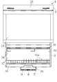
図1は昇降式吊り戸棚1の内キャビネット3を下降させた状態の正面図、図2は同じく下降させ、外キャビネット2の前面扉を開いた状態の概略断面図である。
外キャビネット2は下方を開放したもので、前面上部には幕板23及び矩形の枠に透光性を備えたプラスチック或いはガラスを嵌め込んだ開閉自在な扉24を設けてある。幕板23の左右にはルーバー或いは穴を穿って昇降装置のモータの熱を逃がすようにしてある。透光性を備えた部材を嵌め込んだのは内部への収納状態を透かして確認できるようにするためである。
内キャビネット3は、天井或いは壁面に固定される外キャビネット2内で昇降するもので、前面を開口させ、内部には取り外し自在な棚板32を一乃至複数段設けるようにしてある。
その天板33上にはヒータ及びファンからなる乾燥機5を載置して、内部に温風を供給するようになっている。
【0010】
内キャビネット3の下面奥長手方向には、手暗がりを避けるための蛍光灯などの照明器具6を設けるようにしてある。
そして、内キャビネット3の下面手前側には、比較的大型でコ字状をなし、握り部位が断面円形或いは楕円形というように握り易いように、しかも、内キャビネット3の前面より突出しないようにした操作ハンドル7を設けるようにする。
【0011】
この操作ハンドル7の中央前面には、突出する起倒自在な操作スイッチ8を設けてある。この操作スイッチ8は常態では床面と平行となって停止するようになっており、起倒するとスイッチが投入されるようになっており、起すと内キャビネット3を上昇させ、倒すと内キャビネット3が下降するように内キャビネット3の昇降動作に合わせて上下させるようにしてある。
さらに、この操作ハンドル7の一側前面には、乾燥機5及び照明器具6用のタッチパネル式などで構成したスイッチ群9、9や必要に応じて乾燥機5の作動状態を表わす表示ランプなどを設けるようにしている。
なお、内キャビネット3の昇降手段は、これまでの説明に限定されず、例えば手動であったり、上昇させるための補助手段としてガススプリングなどを用いるものであってもよい。
【0012】
この内キャビネット3は、概略図1及び図3に示すように側板34、34の前後に複数対の金属製のフレーム35、35、36、36を取り付け固定し、フレーム35、36に棚板32の前後端縁を架設し、フレーム36には背板37を嵌め込むようにしてある。
この金属製のフレーム35、36は、望ましくはアルミニウムの押出成形品から形成されるものである。
フレーム35は前述のように、ほぼ断面方形をなすフレーム本体35aの内側面中央に短い突条からなる棚受け35bを設け、この棚受け35bと平行し断面L型をなす長い棚受け35cを延設するようにし、フレーム本体35aの外側端より垂下片35dを連設し、この垂下片35dの背面に溝条35eを形成すべく短い間隔をもって短い内垂下片35fを形成してある。
また、フレーム本体35aの内部に長手方向を切り欠いてなる筒体35g、35gを設け、その端部にめねじ(図示せず)をきって側板34の外側からビスをねじ込み止められるようにしてある。
【0013】
フレーム36は、側板34の後端に配置し、棚板32の奥端を支持すると共に、背板37を嵌め込むようにするものである。
フレーム36は、ほぼ断面方形をなすフレーム本体36aの、内側面中央に短い突条からなる棚受け36bを設け、この棚受け36bと平行し断面L型をなすような棚受け36cを延設するようにし、フレーム本体36aの外側面は上下にその儘延設するようにし、上部は背板の一部となる起立片36dとし、この起立片36dの端縁は二股に構成して背板37の縁を受け入れる被掛止部36eとし、下部には、垂下片36fを連設し、この垂下片36fの内側に溝条36gを形成するようフレーム本体36aより短い内垂下片36hを形成してある。溝条36gには背板37の上端縁を嵌め込むようにする。
また、フレーム本体36aの内部には、長手方向を切り欠いてなる筒体36i、36iを設け、これら筒体36iの両端部にはめねじ(図示せず)をきって側板34の外側からビスをねじ込み止めるようにしてある。
【0014】
棚板32は、その前端及び後端を夫々フレーム35、36の棚受け35b、36bに架設させ掛け止めるようにするもので、清掃などの便宜に配慮して取り外し自在としてある。
昇降式吊り戸棚1を乾燥庫とする場合には、棚板32は、パンチングメタルや網籠体などにて構成して空気が上下に流れるようにする。
下段の棚板32には規則的な丸穴や溝穴を穿ち、ここに金属線材をコ字状に屈曲して形成する皿立て32aを櫛比するように渡してある。図示しないが、必要に応じて箸立てなどを取り外し自在に設けるようにする。
最下段の棚板32の下には傾斜する水受皿38をフレーム35、36の下の棚受け35c、36cに渡すようにしてある。水受皿38で集められた水は、内キャビネット3の前面より引き出し自在な集水トレー39に導かれ、捨てられるようになっている。
【0015】
図4は、フレーム35、35を側板34の上端の前後に配置して天板33を棚板のように取り付ける様子を示すもので、フレーム35は棚板を受けるばかりでなく、側板34と天板33の連結部材及び天板33、側板34と背板37の連結部材として用い、部材の共通化を図ることができることを明らかにする。
勿論、フレーム35、36を側板34、34の前後に渡して棚板32を架設するのみに用いるようにすることもできる。
【0016】
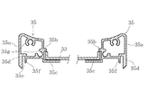
図5は、内キャビネット3の側板34、34(図示せず)の前後に取り付け固定するフレーム35、36及び背板37の別の実施の形態を示すものである。
前述のフレーム35、36とは形状は異なるものの、アルミニウムの押出成形品で形成するのが好適なもので、機能的には同一であるので相当する箇所に同一の符号を付して詳細な説明は省略する。
背板37は、部屋の中央に流し台を含む厨房家具が配置される対面キッチンや壁面に向かって流し台を含む厨房家具が配置されるものの窓がある場合に、採光に配慮して前面に多数の小孔37aを穿ったものとしたものを示す。
この実施の形態ではフレーム36に背板37を嵌め込み、背板の一部ともなる起立片36dを高くしたことで、背板37が小孔37aを穿ったものであっても箸やフォークのように長いもので先端が小孔37aに入りがちであっても阻止することができるので、内キャビネットが上昇するときに挟まったりして支障を来したり、故障の原因となることを防ぐことができる。
【0017】
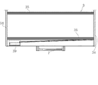
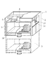
図6、図7は別の実施の形態に係るもので、図6は扉24を外した状態の昇降式吊り戸棚1を、図7は内キャビネット3を示すものである。
これは全体として間口を広くし、内キャビネット3の最下段の棚板32の下に配置する水受皿38を一側端部に傾斜するような構成とし、集水トレー39も合わせて側端部に設けるようにしたものである。
このように間口が広いものであるので、棚板32は複数に分割して着脱し易いようにしている。
これまでの実施例では複数段の棚板32を設けるようにしているが、棚板32は一段のものであってもよい。
【0018】
【発明の効果】
この発明は以上のような構成からなるもので、請求項1の発明では、内キャビネットの両側板間の前後端部に複数対の金属製のフレームを取り付けるようにしたので、内キャビネットの前面が開放していてもフレームにて剛性を備えることができ、また、二段の棚受けを設けるようにしたので、下段の棚受けには水受皿や天板を取り付けるようにすることもできるのである。内キャビネットの背板に多数の小孔を穿ったので、通気性、採光性を付与することができるのである。
【0019】
請求項2の発明では、昇降式吊り戸棚を全体として間口を広く構成したので、使い勝手が良くなるように棚板を複数に分割して着脱を容易にしたのである。
【図面の簡単な説明】
【図1】 この発明に係る昇降式吊り戸棚の正面図である。
【図2】 図1の概略縦断面図である。
【図3】 フレーム35、36の取り付け状態を示す端面図である。
【図4】 フレーム35への天板33への取り付け状態を示す断面図である。
【図5】 この発明の別の実施の形態を示す要部斜視図である。
【図6】 さらに別の実施の形態を示す扉24を外した状態の斜視図である。
【図7】 図6の内キャビネット3の要部正面図である。
【図8】 従来の昇降式吊り戸棚の斜視図である。
【図9】 従来の昇降式吊り戸棚の昇降機構の要部を示す断面図である。
【符号の説明】
1 昇降式吊り戸棚
2 外キャビネット
3 内キャビネット
32 棚板
34 側板
35 フレーム
36 フレーム
37 背板
4 駆動装置
5 乾燥機[0001]
BACKGROUND OF THE INVENTION
The present invention relates to an elevating-type hanging cabinet that is adopted for a part or all of a hanging cabinet arranged in series on the upper part of a wall cabinet, a sink, a cooking table, and a gas table that constitute a part of a system kitchen.
Then, the elevating type hanging cabinet is lowered to the eye level so that it can be effectively used as a tableware storage and a tableware storage dryer.
Moreover, by arranging this elevating-type hanging cupboard close to the sink or the dishwasher, it is possible to improve the appearance of the sink, improve the appearance, and improve the efficiency of the cooking operation.
In other words, in the past, wet dishes and cooking utensils that had been washed have been placed on a drainage plate placed on a counter or a draining plate placed over a sink, and dried, so the cooking surface and counter surface of kitchen furniture tend to be narrow. This is because the.
[0002]
[Prior art]
Conventionally, a hanging cabinet as a storage for hanging and fixing on a wall surface or ceiling has been arranged on the upper part of kitchen furniture such as a system kitchen.
The hanging cupboard is at the top, making it difficult to take in and out, and often used to store infrequently used utensils and dishes. And if you put many items in the back and top of the hanging cupboard, you could get lost because you couldn't reach your eyes.
It is desirable from the viewpoint of ease of use to store tableware and small pots, chopsticks, spoons that are frequently used every day and store them in the vicinity of a sink and a dishwasher.
Therefore, in order to make effective use of the hanging cupboard, the hanging cupboard can be moved up and down as a whole, or a plastic rack that can be swung down is stored in the hanging cupboard, and the rack is opened to the eye level by opening the door. A hanging cabinet with a structure for swiveling down has been proposed and put into practical use.
[0003]
Furthermore, a hanging cupboard has been proposed in which an inner cabinet is slidably provided in an outer cabinet that opens downward, and a driving device that raises and lowers the inner cabinet and a dryer that faces the inner cabinet are provided as a drying cabinet (specialty). (Kaihei 11-9355, JP-A-11-206475, JP-A-11-206476, JP-A-11-206477, JP-A-11-229791, JP-A-11-229800, etc.).
[0004]
This lift-
[0005]
A
The
[0006]
[Problems to be solved by the invention]
The present invention was developed for the purpose of providing a structure for increasing the rigidity of the entire inner cabinet in such a conventional
That is, in the conventional form, it has been common to provide latching protrusions on both side plates of the inner cabinet, and to detachably mount the shelf plate here.
In such a structure, since the front surface of the inner cabinet is open, the rigidity as a whole is insufficient. If the shelf board is fitted, the lack of rigidity is compensated, but it may be removed for cleaning or the like, and the risk of deformation as a whole could not be eliminated.
Further, if the entire shelf is structured to have a wide frontage, the center of the shelf board is bent due to the weight of the storage if the shelf board in the inner cabinet is only supported on both sides.
[0007]
[Means for Solving the Problems]
In order to solve the above-mentioned problem, the gist of the invention of
[0008]
The gist of the invention of
[0009]
DETAILED DESCRIPTION OF THE INVENTION
The present invention will be described below with reference to the embodiments shown in the drawings.
Since the lifting device and the dryer have substantially the same configuration as the conventional one, detailed description is omitted.
FIG. 1 is a front view of the
The
The
On the
[0010]
A lighting fixture 6 such as a fluorescent lamp for avoiding hand darkness is provided in the longitudinal direction at the bottom of the
The lower side of the
[0011]
On the front surface of the center of the
Further, on one side front surface of the
In addition, the raising / lowering means of the
[0012]
As shown in FIGS. 1 and 3, the
The metal frames 35 and 36 are preferably formed from an aluminum extrusion.
As described above, the
Also,
[0013]
The
The
Further, cylinder bodies 36i and 36i formed by cutting out the longitudinal direction are provided inside the
[0014]
The
When the elevating-
The
Under the
[0015]
FIG. 4 shows a state in which the
Of course, the
[0016]
FIG. 5 shows another embodiment of the
Although the shape is different from that of the
The
In this embodiment, the
[0017]
FIGS. 6 and 7 relate to another embodiment. FIG. 6 shows the elevating-
As a whole, the frontage is widened, the
Since the frontage is wide as described above, the
In the embodiments so far, a plurality of
[0018]
【The invention's effect】
The present invention is configured as described above. In the first aspect of the present invention, a plurality of pairs of metal frames are attached to the front and rear end portions between both side plates of the inner cabinet. Even if it is open, it can have rigidity in the frame, and since it is provided with a two-stage shelf holder, it is also possible to attach a water tray or top plate to the lower shelf holder . Since many small holes are made in the back plate of the inner cabinet, air permeability and daylighting can be imparted.
[0019]
In the second aspect of the present invention, since the front and rear lifting cabinets are configured to be wide as a whole, the shelf board is divided into a plurality of parts so as to be easy to use, and is easily attached and detached.
[Brief description of the drawings]
FIG. 1 is a front view of an elevating type hanging cupboard according to the present invention.
FIG. 2 is a schematic longitudinal sectional view of FIG.
FIG. 3 is an end view showing how the
4 is a cross-sectional view showing a state in which the
FIG. 5 is a perspective view of a main part showing another embodiment of the present invention.
FIG. 6 is a perspective view showing a state in which a
7 is a front view of the main part of the
FIG. 8 is a perspective view of a conventional elevating type hanging cabinet.
FIG. 9 is a cross-sectional view showing a main part of a conventional lifting mechanism of a lifting cabinet.
[Explanation of symbols]
DESCRIPTION OF
Claims (2)
内キャビネットの両側板間の前後端部に複数対の金属製のフレームを取り付け、フレームの夫々に、内側面中央に短い突条からなる棚受け及びこの棚受けと平行し断面L型をなす長い棚受けを延設し、このフレームに棚板の前後端縁を架設し、背面側のフレームには多数の小孔を穿った背板を取り付けるようにしたことを特徴とする昇降式吊り戸棚。In an elevating type hanging cabinet provided with an inner cabinet with the front opened in a slidable manner inside an outer cabinet with the lower open, and a drive device for raising and lowering the inner cabinet,
A plurality of pairs of metal frames are attached to the front and rear end portions between the two side plates of the inner cabinet, and each frame has a shelf support composed of a short ridge at the center of the inner surface and a long L section in parallel with the shelf support. An elevating-type hanging cabinet with a shelf holder extended, a front and rear edge of the shelf board erected on the frame, and a back plate having a large number of small holes attached to the frame on the back side.
Priority Applications (1)
| Application Number | Priority Date | Filing Date | Title |
|---|---|---|---|
| JP2001197799A JP3824504B2 (en) | 2001-06-29 | 2001-06-29 | Lifting cabinet |
Applications Claiming Priority (1)
| Application Number | Priority Date | Filing Date | Title |
|---|---|---|---|
| JP2001197799A JP3824504B2 (en) | 2001-06-29 | 2001-06-29 | Lifting cabinet |
Related Child Applications (1)
| Application Number | Title | Priority Date | Filing Date |
|---|---|---|---|
| JP2005266280A Division JP4828188B2 (en) | 2005-09-14 | 2005-09-14 | Lifting cabinet |
Publications (3)
| Publication Number | Publication Date |
|---|---|
| JP2003009962A JP2003009962A (en) | 2003-01-14 |
| JP2003009962A5 JP2003009962A5 (en) | 2004-12-09 |
| JP3824504B2 true JP3824504B2 (en) | 2006-09-20 |
Family
ID=19035346
Family Applications (1)
| Application Number | Title | Priority Date | Filing Date |
|---|---|---|---|
| JP2001197799A Expired - Lifetime JP3824504B2 (en) | 2001-06-29 | 2001-06-29 | Lifting cabinet |
Country Status (1)
| Country | Link |
|---|---|
| JP (1) | JP3824504B2 (en) |
Families Citing this family (3)
| Publication number | Priority date | Publication date | Assignee | Title |
|---|---|---|---|---|
| JP2008303562A (en) * | 2007-06-06 | 2008-12-18 | Sanou:Kk | Water storage tower |
| JP5072918B2 (en) * | 2009-07-22 | 2012-11-14 | 東芝コンシューマエレクトロニクス・ホールディングス株式会社 | Electric lifting cabinet |
| JP5248435B2 (en) * | 2009-07-22 | 2013-07-31 | 東芝コンシューマエレクトロニクス・ホールディングス株式会社 | Electric lifting cabinet |
-
2001
- 2001-06-29 JP JP2001197799A patent/JP3824504B2/en not_active Expired - Lifetime
Also Published As
| Publication number | Publication date |
|---|---|
| JP2003009962A (en) | 2003-01-14 |
Similar Documents
| Publication | Publication Date | Title |
|---|---|---|
| JP4828188B2 (en) | Lifting cabinet | |
| JPS6254002B2 (en) | ||
| JP3824504B2 (en) | Lifting cabinet | |
| JP3735276B2 (en) | Lifting cabinet | |
| JP2003009962A5 (en) | ||
| JP2003009961A5 (en) | ||
| CN215737658U (en) | Wardrobe with ventilation side wall | |
| CN215271433U (en) | Glass light-transmitting all-aluminum plate type pull basket | |
| CN112021800B (en) | Wardrobe convenient to get and put clothing | |
| CN213786237U (en) | Wooden cupboard with dampproofing function | |
| CN212108589U (en) | Disinfection cabinet structure in integrated kitchen | |
| JP2003009961A (en) | Vertically moving hanging cupboard | |
| CN208436120U (en) | Disinfection cabinet draws basket and disinfection cabinet | |
| CN207898410U (en) | A kind of Multifunctional kitchen rack | |
| CN215650641U (en) | Side frame mounting structure of oven | |
| CN209763211U (en) | Integrated cupboard cigarette machine that over-and-under type was adjusted | |
| CN213786141U (en) | Wardrobe with adjustable inner space | |
| KR200442769Y1 (en) | Multipurpose shelf of kimchi refrigerator | |
| CN214341063U (en) | Multi-sink door-opening cabinet with easily-distinguished storage positions | |
| CN215502020U (en) | Drawer for showcase | |
| CN220631458U (en) | Multifunctional counter | |
| CN221129431U (en) | Cake display cabinet with front-mounted illumination LED lamp | |
| CN215570685U (en) | Fume exhaust fan | |
| CN215225695U (en) | Spliced multifunctional wardrobe | |
| CN215126111U (en) | Movable rotary cabinet |
Legal Events
| Date | Code | Title | Description |
|---|---|---|---|
| A977 | Report on retrieval |
Free format text: JAPANESE INTERMEDIATE CODE: A971007 Effective date: 20050713 |
|
| A131 | Notification of reasons for refusal |
Free format text: JAPANESE INTERMEDIATE CODE: A131 Effective date: 20050726 |
|
| A521 | Written amendment |
Free format text: JAPANESE INTERMEDIATE CODE: A523 Effective date: 20050914 |
|
| A131 | Notification of reasons for refusal |
Free format text: JAPANESE INTERMEDIATE CODE: A131 Effective date: 20051115 |
|
| A131 | Notification of reasons for refusal |
Free format text: JAPANESE INTERMEDIATE CODE: A131 Effective date: 20060328 |
|
| A521 | Written amendment |
Free format text: JAPANESE INTERMEDIATE CODE: A523 Effective date: 20060425 |
|
| TRDD | Decision of grant or rejection written | ||
| A01 | Written decision to grant a patent or to grant a registration (utility model) |
Free format text: JAPANESE INTERMEDIATE CODE: A01 Effective date: 20060530 |
|
| A61 | First payment of annual fees (during grant procedure) |
Free format text: JAPANESE INTERMEDIATE CODE: A61 Effective date: 20060627 |
|
| R150 | Certificate of patent or registration of utility model |
Free format text: JAPANESE INTERMEDIATE CODE: R150 Ref document number: 3824504 Country of ref document: JP Free format text: JAPANESE INTERMEDIATE CODE: R150 |
|
| FPAY | Renewal fee payment (event date is renewal date of database) |
Free format text: PAYMENT UNTIL: 20090707 Year of fee payment: 3 |
|
| FPAY | Renewal fee payment (event date is renewal date of database) |
Free format text: PAYMENT UNTIL: 20100707 Year of fee payment: 4 |
|
| R250 | Receipt of annual fees |
Free format text: JAPANESE INTERMEDIATE CODE: R250 |
|
| FPAY | Renewal fee payment (event date is renewal date of database) |
Free format text: PAYMENT UNTIL: 20110707 Year of fee payment: 5 |
|
| R250 | Receipt of annual fees |
Free format text: JAPANESE INTERMEDIATE CODE: R250 |
|
| FPAY | Renewal fee payment (event date is renewal date of database) |
Free format text: PAYMENT UNTIL: 20120707 Year of fee payment: 6 |
|
| R250 | Receipt of annual fees |
Free format text: JAPANESE INTERMEDIATE CODE: R250 |
|
| FPAY | Renewal fee payment (event date is renewal date of database) |
Free format text: PAYMENT UNTIL: 20120707 Year of fee payment: 6 |
|
| FPAY | Renewal fee payment (event date is renewal date of database) |
Free format text: PAYMENT UNTIL: 20120707 Year of fee payment: 6 |
|
| FPAY | Renewal fee payment (event date is renewal date of database) |
Free format text: PAYMENT UNTIL: 20130707 Year of fee payment: 7 |
|
| R250 | Receipt of annual fees |
Free format text: JAPANESE INTERMEDIATE CODE: R250 |
|
| R250 | Receipt of annual fees |
Free format text: JAPANESE INTERMEDIATE CODE: R250 |
|
| R250 | Receipt of annual fees |
Free format text: JAPANESE INTERMEDIATE CODE: R250 |
|
| R250 | Receipt of annual fees |
Free format text: JAPANESE INTERMEDIATE CODE: R250 |
|
| R250 | Receipt of annual fees |
Free format text: JAPANESE INTERMEDIATE CODE: R250 |
|
| R250 | Receipt of annual fees |
Free format text: JAPANESE INTERMEDIATE CODE: R250 |
|
| R250 | Receipt of annual fees |
Free format text: JAPANESE INTERMEDIATE CODE: R250 |
|
| R250 | Receipt of annual fees |
Free format text: JAPANESE INTERMEDIATE CODE: R250 |
|
| R250 | Receipt of annual fees |
Free format text: JAPANESE INTERMEDIATE CODE: R250 |
|
| EXPY | Cancellation because of completion of term |