【0001】
【発明の属する技術分野】
本発明は、例えば自動販売機のドアパネルに設けられた施錠装置などの防盗性を高めるために、施錠装置などの表面を開閉するスライドカバーを閉鎖時に施錠,解錠するスライドカバーの錠装置に関する。
【0002】
【従来の技術】
自動販売機のドアパネルに設けられた施錠装置は、管理人の所有する正規のキーで施錠,解錠することができ、他人が勝手にドアパネルを開けて商品を盗むことを防止している。
然し、人通りの途絶えた夜間を利用して、ピッキングツールを使用して不正解錠したり、或いは、ドリルで施錠装置を穿孔,破壊してドアパネルを強引に開ける悪質な盗難事故が発生することがある。
【0003】
不正解錠或いは施錠装置の破壊による盗難事故を防止するために種々の方法が工夫され、施錠装置をピッキングされ難い構造としたり、高硬度材を組み込んで破壊され難い構造とする方法の他に、ドアパネルの開扉を阻止する機構を別に設け、この機構に施錠装置を設ける二重施錠方式や、施錠装置の表面にスライドカバーを設け、このスライドカバーに施錠装置を設ける二重施錠方式(特開平9−78898号公報参照)などがある。
【0004】
上記の公報に記載の「防盗用カバー装置」は、ドアパネルに装着された飛び出し型ハンドルとそのハンドルに設けられた錠装置を全面被覆する位置に、開口を有するベースを取り付け、ベースに摺動可能に設けられ、開口を開閉するカバーボックスに錠前を設けたものである。
カバーボックスは開口を閉鎖した状態で施錠され、解錠により開口を開放する方向に移動可能になり、開口を通してハンドルの錠装置を解錠すると、ハンドルが前面に突出して回動操作が可能になり、ハンドルを解錠方向にまわすと、ドアパネルを開くことができる。
【0005】
【発明が解決しようとする課題】
このような二重施錠方式では、ハンドルの錠装置を施錠した後に、カバーボックスを閉鎖する手間と、カバーボックスを施錠操作する手間が必要になるので、二重施錠方式でないものに比較して施錠,解錠の手間が約2倍になり、煩わしくなる問題がある。
本発明は、かかる課題を解決することを目的とし、施錠の手間が煩わしくないスライドカバーの錠装置を提供するものである。
【0006】
【課題を解決するための手段】
上記目的を達成するために、本発明のスライドカバーの錠装置は、
パネルに固着されパネルを露出する開口を有するカバーベースに、上記開口を開閉するスライドカバーを摺動可能に装着し、上記開口を閉鎖した上記スライドカバーを施錠,解錠する錠装置において、
上記スライドカバーの閉鎖側の先端部の裏面に被係止部を設け、上記カバーベースに取り付けられる錠前のロータの後端部に固着されるロックプレートに、外周面に形成される係合段部と施錠方向に回動したときに上記被係止部に係合する施錠アームを設けると共に、上記ロックプレートを施錠方向に付勢するロックスプリングを設け、上記カバーベース内に枢着されるロックストッパに閉鎖時の上記スライドカバーに押動される閉鎖感知部と、該閉鎖感知部が押動されたときに上記係合段部との係合が解除される係合突起を設けると共に、上記閉鎖感知部が上記スライドカバーに向けて突出する方向に上記ロックストッパを回動付勢するストッパスプリングを設けたものである。
【0007】
或いは、本発明のスライドカバーの錠装置は、
パネルに固着されパネルを露出する開口を有するカバーベースに、上記開口を開閉するスライドカバーを摺動可能に装着し、上記開口を閉鎖した上記スライドカバーを施錠,解錠する錠装置において、
上記スライドカバーの閉鎖側の先端部の裏面に被係止部を突設し、上記カバーベースに取り付けられる錠前のロータの後端部に固着されるロックプレートに、円周方向に傾斜する円周傾斜面と該円周傾斜面の両端にそれぞれつながる施錠面と解錠面を設けたカム面を設け、上記カバーベースに挿入されるロック部材の先端に、閉鎖時のスライドカバーの上記被係止部に係合する係止面と、該係止面の反対側に形成される傾斜面を設け、上記ロック部材を先端方向に付勢するスプリングを設けると共に、該スプリングの付勢により上記カム面に圧接する押動突起を上記ロック部材に設けたものである。
【0008】
上記カバーベースとスライドカバーの摺動面の一方に、上記スライドカバーの開閉方向に平行な開放規制溝を設け、他方に設けた底付きの孔に鋼球と該鋼球を上記開放規制溝に押圧する押圧スプリングを挿入することができる。
或いは、上記スライドカバーの裏面に上記スライドカバーの開閉方向に平行なラックを設け、上記カバーベースに一方向ダンパを設け、上記ラックに噛合するピニオンの軸を上記一方向ダンパに固着することにより、上記スライドカバーの閉鎖方向移動を開放方向移動よりも軽くすることができる。
【0009】
【発明の実施の形態】
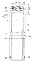
本発明の実施の形態について図面を参照して説明すると、図1〜図11は本発明の第1実施例を示し、図1はスライドカバーが開放状態にあるときのスライドカバーの錠装置の斜視図、図2は図1の正面図、図3は図1の側面図、図4は図1の背面図である。
図1に示すように、スライドカバー1はカバーベース2に摺動可能に装着され、カバーベース2はドアパネルDの飛び出し型ハンドル3の位置に設けられる。
【0010】
施錠中の飛び出し型ハンドル3は、ドアパネルDに設けられたハンドルケース4(図5参照)の前面に形成されたハンドル収容凹部に没入しているが、ハンドル3に設けられたシリンダ錠5の鍵孔6(図1参照)にキーを挿入して解錠すると、ハンドル3が突出し(図5参照)、回動操作可能になる。
ハンドル3を回動操作すると、ドアパネルDと販売機本体のケースとのロックが解除され開扉可能になる。
【0011】
カバーベース2は、矩形状の輪郭を有する板状に形成され、中央部に矩形状の大きな開口7が設けられ、開口7の両側内面に案内レール8が設けられ、開口7の上方に肉厚部分9が形成され、開口7の下方にストッパ10が突設される(図1,図2,図5参照)。
カバーベース2の裏面に突出する複数のボルト11が、ドアパネルDに穿設された孔に挿通され、ドアパネルDの内側からナットで緊締されて、カバーベース2がドアパネルDに固着され、開口7よりハンドル3が露出する。
【0012】
案内レール8に摺動可能に装着されるスライドカバー1は、スライドカバー1の閉鎖方向の先端部(図4において上端部)の裏面に軸形状の被係止部12が突出し、全開したときにカバーベース2のストッパ10に当接する全開量規制用の突起13が設けられる(図4参照)。
スライドカバー1の横幅はカバーベース2の横幅とほぼ同一であり(図1参照)、スライドカバー1の閉鎖方向の先端部(図1において上側)は、カバーベース2の厚肉部分9の裏側に形成された凹部14(図5参照)に挿入されるようにするため、両側端に切欠部15が設けられている(図1参照)。
【0013】
カバーベース2の厚肉部分9に、キーのマグネットによりロータ17が回動可能になる錠前16が挿入,固着され、錠前16のロータ17の後端部は、厚肉部分9の裏面に形成された凹部18より突出し、この後端部にロックプレート19の中央部が固着される(図4,図5参照)。
ロックプレート19の略円形の外周面には、係合段部20,施錠アーム21,ばね支持突起22が形成される。
【0014】
施錠アーム21の先端に屈曲した鉤状部21aが形成され、スライドカバー1が全閉位置にあるときに鉤状部21aは被係止部12に係脱可能である。
凹部18の底面にばね支持軸23が立設され、ばね支持軸23とばね支持突起22にロックスプリング24が張架される。
従って、ロックプレート19はロータ17を中心として図4の時計方向に付勢される。
【0015】
図4において、ロックプレート19の左側には、凹部18に立設される支軸25にロックストッパ26が枢着される。
ロックストッパ26には、ロックプレート19の係合段部20に係脱可能な係合突起27と、閉鎖感知部28が設けられ、閉鎖感知部28と凹部18の側壁面とに間にストッパスプリング50が挿入される。
従って、ロックストッパ26は図4において反時計方向に付勢され、閉鎖感知部28が開口7の方向に突出している。
【0016】
次に、以上のように構成されたスライドカバーの錠装置の作用を、施錠状態,解錠,開扉操作,閉扉,施錠操作の順に説明する。
施錠状態では、スライドカバー1は開口7を全閉し、切欠部15が厚肉部分9の下端面に当接している(図6,図8,図9参照)。
錠前16が施錠されているので、施錠角度にあるロックプレート19は、施錠アーム21の鉤状部21aが被係止部12に係合し(図7参照)、スライドカバー1は開放不能である。
ロックストッパ26は、スライドカバー1の施錠方向の先端(上端)に閉鎖感知部28を押されて時計方向に回動した位置にあり、係合突起27は係合段部20から外れている(図7参照)。
【0017】
このような施錠状態において、キーKを錠前16に装着すると、ロータ17が回動可能になり、キーKを解錠方向に回動操作するとロックプレート19が、ロックスプリング24の引張力に抗して図7において反時計方向に回動し、施錠アーム21の鉤状部21aが被係止部12から離脱してスライドカバー1が開放可能になり(図4参照)、ロックストッパ26の閉扉感知部28がスライドカバー1を押動してスライドカバー1が僅かに開かれるが、係止突起27が下方に移動した係合段部20に係合するので、ロックストッパ26はそれ以上回動しない。
【0018】
スライドカバー1を下方に全開すると、開口7よりハンドル3が露出し(図1参照)、ハンドル3のシリンダ錠5の鍵孔6にキーを挿入して解錠すると、ハンドル3が回動操作可能な位置まで突出する(図5参照)。
ハンドル3を操作するとドアパネルDを開くことができる。
【0019】
ドアパネルDを閉鎖した後にハンドル3を押し込み施錠した後に、スライドカバー1を閉めると、閉鎖感知部28を押されたロックストッパ26が時計方向に回動し、ロックストッパ26の係合突起27が係合段部20から外れ、ロックスプリング24の付勢力を受けているロックプレート19が施錠方向に回動して、施錠アーム21の鉤錠部21aが被係止部12に係合し、スライドカバー1は施錠される(図7の状態に戻る)。
従って、スライドカバー1を閉めるだけでスライドカバー1が施錠され、キーによる施錠操作を行う面倒がなくなる。
【0020】
以上の第1実施例では、マグネット形式の錠前16を使用したが、シリンダ錠を使用してもよい。
又、閉鎖感知部28で僅かに押されたスライドカバー1が自重で急激に落下するのを防止するために、スライドカバー1とカバーベース2の摺動面の一方(本実施例ではカバーベース2)に底付きの孔29を設け、底付きの孔29に、鋼球30と、鋼球30を突出する方向に付勢するスプリング31を挿入し(図10参照)、他方に(本実施例ではスライドカバー1に)、全閉から僅かに開扉するときに鋼球30が浅く係入する開放規制溝32を有する(図4参照)自重落下防止機構を設けるとよい。
【0021】
スライドカバー1が全閉しているとき、鋼球30は開放規制溝32の下端32aに位置しているため、キーKの解錠操作によってスライドカバー1は自重で鋼球30が開放規制溝32の上端32bに位置するまで移動することができる。
このような自重落下防止機構を設けた場合には、解錠操作により施錠アーム21の鉤錠部21aが被係止部12から離脱して、スライドカバー1が自重落下し、鋼球30が開放規制溝32の端部32bに到達したときに鋼球30が軽く係止され、スライドカバー1が一時停止する。
【0022】
スライドカバー1が一時停止する位置は、図11に示すように、スライドカバー1が隙間Sだけ開口した位置であり、この開口量によって解除が目視確認されると共に、急激な落下による危険が防止される。
一時停止したスライドカバー1の上端を押さえると、鋼球30が開放規制溝32の端部32aを乗り越えるので、そのままスライドカバー1を全開することができる。
【0023】
図12〜図14は、本発明の第2実施例を示す図面であり、第1実施例との相違点を説明すると、ロックプレート19に代えてロックプレート33を設け、ロックストッパ26に代えてロック部材34を設け、被係止部12に代えて被係止部35を設けるものである。
なお、マグネット式の錠前16に代えてシリンダ錠式の錠前36を使用しているが、第1,第2実施例の何れも錠前16或いは36を選択して使用することができる。
【0024】
第2実施例のその他の部品は第1実施例のものと同一機能を有するので、第1実施例と同一符号を付してその詳細説明を省略する。
図13に示すように、カバーベース2の厚肉部分9に錠前36を装着し、厚肉部分9の裏面に突出する錠前36のロータ37にロックプレート33の中央部を固着する。
【0025】
ロックプレート33は、円形の中央部の外面から突出する扇形状突起38が形成され、扇形状突起38の裏面には、円周方向に向かって傾斜する円周傾斜面39aと、円周傾斜面39aの両端にそれぞれ接続する施錠面39bと解錠面39cとを有するカム面39が設けられる(図14参照)。
解錠面39cは、施錠面39bよりもカバーベース2の表面より遠ざかる位置にある。
【0026】
ロック部材34は、カバーベース2に設けられた貫通孔に挿入され、カバーベース2の裏面に立設されたばね受け41とロック部材34との間に挿入されるスプリング42により、ロック部材34は先端部(図13において右端部)がカバーベース2の表面から突出する方向に付勢され、ロック部材34の後端部より上方に突出する押動突起43がカム面39に圧接する。
【0027】
スライドカバー1の被係止部35は、スライドカバー1の閉鎖方向先端部の裏面より突出し、ロック部材34の先端部には、スライドカバー1閉鎖時の被係止部35に係合する係止面34aが設けられ、係止面34aの反対面に傾斜面34bが設けられる。
【0028】
以上のように構成される第2実施例のスライドカバーの錠装置の作用を、施錠状態,解錠,開扉操作,閉扉,施錠操作の順に説明する。
施錠状態では、スライドカバー1が開口7を全閉し、ロックプレート33は施錠角度にあり、ロック部材34の押動突起43はカム面39の施錠面39bに当接し、突出する方向に付勢されているロック部材34は突出した位置にあり、係止面34aがスライドカバー1の被係止部35に係合しているので、スライドカバー1は施錠されている(図13,図14参照)。
【0029】
錠前36の鍵孔44に挿入したキーを解錠方向に回動操作すると、ロータ37と共にロックプレート33が図14において反時計方向に回動し、円周傾斜面39aで押動突起43を押されたロック部材34が後退し、解錠面39cの位置において係止面34aが被係止部35から離脱するのでスライドカバー1が開閉可能になり、スライドカバー1を開く。
キーを施錠角度に戻してキーを引き抜くと、スプリング42により押動突起43が円周傾斜面39aに沿って移動し、ロック部材34が施錠位置(図13参照)に復帰する。
【0030】
スライドカバー1を閉めていくと、全閉寸前の位置で被係止部35がロック部材34の傾斜面34bに当り、傾斜面34bを押されたロック部材34が後退するので、スライドカバー1が全閉位置まで移動し、被係止部35が係止面34aを通過したときに、ロック部材34が再び突出し、係止面34aと被係止部35が係合するので、スライドカバー1が施錠される。
【0031】
スライドカバー1が解錠したときに、自重により急激に落下するのを防止するため、図12に示すように、スライドカバー1の裏面に、開閉方向に平行な2条のラック45を設け、カバーベース2に一方向ダンパー46を設け、ラック45に噛合するピニオン47に、一方向ダンパー46に固着される軸を設ける。
一方向ダンパー46は、スライドカバー1が下方に開くときにピニオン47の回動に負荷を与えてスライドカバー1の急激落下を防止し、スライドカバー1が上方に閉まるときには無負荷になるものである。
この急激落下を防止する機構は、第1,第2実施例の何れにも適応することができる。
【0032】
【発明の効果】
本発明は以上のように構成されているので、以下に記載されるような効果を奏する。
(1) 本発明のスライドカバーの錠装置は、スライドカバーを閉めるだけで自動施錠されるので、二重施錠方式に生じる煩わしい手間が簡単になる効果がある。
(2) 本発明のスライドカバーの錠装置は、構造が簡単であり、安価に提供できる利点がある。
(3) 第1実施例のスライドカバーの錠装置では、解錠によってスライドカバーが僅かに開くので、解錠を外部から簡単に目視確認できる。
(4) 鋼球を開放規制溝に係入させた機構、或いはラックに噛合するピニオンを一方向ダンパーに固着させる機構を設けた場合には、解錠と同時にスライドカバーが急激に自重落下する危険を防止することができる。
【図面の簡単な説明】
【図1】スライドカバーが開かれたときの第1実施例のスライドカバーの錠装置の斜視図である。
【図2】図1の正面図である。
【図3】図1の側面図である。
【図4】図1の背面図である。
【図5】スライドカバーが開かれ、ハンドルが突出した状態を説明するスライドカバーの錠装置の縦断面図である。
【図6】施錠状態のスライドカバーの錠装置の斜視図である。
【図7】施錠状態のスライドカバーの錠装置の背面図である。
【図8】図7の正面図である。
【図9】図7の側面図である。
【図10】鋼球を使用した急激落下防止機構の縦断面図である。
【図11】鋼球を使用した急激落下防止機構によりスライドカバーが一時停止した状態を示すスライドカバーの錠装置の背面図である。
【図12】本発明の第2実施例を示すスライドカバーの錠装置を、スライドカバーを除いて見た正面図である。
【図13】図12の縦断面図である。
【図14】図12の背面図である。
【符号の説明】
D ドアパネル
1 スライドカバー
2 カバーベース
7 開口
12 被係止部
16 錠前
17 ロータ
19 ロックプレート
20 係合段部
21 施錠アーム
21a 鉤状部
24 ロックスプリング
26 ロックストッパ
27 係合突起
28 閉鎖感知部
30 鋼球
31 スプリング
32 開放規制溝
33 ロックプレート
34 ロック部材
34a 係止面
34b 傾斜面
35 被係止部
36 錠前
37 ロータ
39 カム面
39a 円周傾斜面
39b 施錠面
39c 解錠面
42 スプリング
43 押動突起
45 ラック
46 一方向ダンパー
47 ピニオン[0001]
BACKGROUND OF THE INVENTION
The present invention relates to a locking device for a slide cover that locks and unlocks a slide cover that opens and closes a surface of the locking device or the like in order to enhance the anti-theft property of a locking device or the like provided on a door panel of a vending machine, for example.
[0002]
[Prior art]
The locking device provided on the door panel of the vending machine can be locked and unlocked with a regular key owned by the manager, preventing others from opening the door panel and stealing goods.
However, a malicious theft accident may occur in which the unlocking is performed using a picking tool or the door panel is forcibly opened by drilling or destroying the locking device with a drill using the nighttime when people are lost. There is.
[0003]
Various methods have been devised to prevent theft accidents due to unauthorized unlocking or destruction of the locking device, in addition to making the locking device a structure that is difficult to pick, or incorporating a high hardness material to make it difficult to break, A mechanism for preventing the door panel from being opened is provided separately, and a double locking system in which a locking device is provided in this mechanism, or a double locking system in which a sliding cover is provided on the surface of the locking device and the locking device is provided on this slide cover 9-78898).
[0004]
The "anti-theft cover device" described in the above publication can be slid on the base by attaching a base with an opening to the position that covers the pop-up type handle attached to the door panel and the lock device provided on the handle. Provided with a lock on the cover box that opens and closes the opening.
The cover box is locked with the opening closed, and can be moved in the direction to open the opening by unlocking. When the handle locking device is unlocked through the opening, the handle protrudes to the front and can be rotated. When the handle is turned in the unlocking direction, the door panel can be opened.
[0005]
[Problems to be solved by the invention]
In such a double locking method, after locking the locking device of the handle, it is necessary to close the cover box and to lock the cover box. , There is a problem that the time and effort of unlocking is approximately doubled and bothering.
The present invention aims to solve such a problem, and provides a slide cover locking device that does not bother the trouble of locking.
[0006]
[Means for Solving the Problems]
In order to achieve the above object, the slide cover locking device of the present invention comprises:
In a locking device that slidably attaches a slide cover that opens and closes the opening to a cover base that has an opening that is fixed to the panel and exposes the panel, and locks and unlocks the slide cover that closes the opening.
An engagement step formed on the outer peripheral surface of the lock plate provided on the back surface of the front end portion on the closing side of the slide cover and fixed to the rear end portion of the lock rotor attached to the cover base And a locking stopper that is pivotally mounted in the cover base, provided with a locking arm that engages with the locked portion when rotated in the locking direction, and a lock spring that urges the lock plate in the locking direction. A closing sensor that is pushed by the slide cover when closed, and an engaging protrusion that is disengaged from the engaging step when the closing sensor is pushed. A stopper spring is provided for rotating and energizing the lock stopper in a direction in which the sensing portion protrudes toward the slide cover.
[0007]
Alternatively, the slide cover locking device of the present invention comprises:
In a locking device that slidably attaches a slide cover that opens and closes the opening to a cover base that has an opening that is fixed to the panel and exposes the panel, and locks and unlocks the slide cover that closes the opening.
A circumferentially inclined circumferential direction is formed on a lock plate that is fixed to a rear end portion of a lock-attached rotor attached to the cover base by projecting a locked portion on the back surface of the front end portion on the closed side of the slide cover. An inclined surface and a cam surface provided with a locking surface and an unlocking surface respectively connected to both ends of the circumferential inclined surface are provided, and the locked portion of the slide cover when closed is provided at the tip of a lock member inserted into the cover base. A locking surface that engages the portion and an inclined surface that is formed on the opposite side of the locking surface, a spring that biases the lock member in the distal direction, and a cam surface that is biased by the spring. The locking member is provided with a pressing projection that presses against the locking member.
[0008]
An opening restriction groove parallel to the opening / closing direction of the slide cover is provided on one of the sliding surfaces of the cover base and the slide cover, and a steel ball and the steel ball are formed in the opening restriction groove on the bottom provided on the other side. A pressing spring for pressing can be inserted.
Alternatively, by providing a rack parallel to the opening and closing direction of the slide cover on the back surface of the slide cover, providing a one-way damper on the cover base, and fixing a pinion shaft meshing with the rack to the one-way damper, The movement of the slide cover in the closing direction can be made lighter than the movement in the opening direction.
[0009]
DETAILED DESCRIPTION OF THE INVENTION
1 to 11 show a first embodiment of the present invention. FIG. 1 is a perspective view of a slide cover locking device when the slide cover is in an open state. 2 is a front view of FIG. 1, FIG. 3 is a side view of FIG. 1, and FIG. 4 is a rear view of FIG.
As shown in FIG. 1, the slide cover 1 is slidably mounted on the cover base 2, and the cover base 2 is provided at the position of the pop-out type handle 3 of the door panel D.
[0010]
The pop-out type handle 3 being locked is immersed in a handle receiving recess formed on the front surface of the handle case 4 (see FIG. 5) provided on the door panel D, but the key of the cylinder lock 5 provided on the handle 3 When a key is inserted into the hole 6 (see FIG. 1) and unlocked, the handle 3 protrudes (see FIG. 5) and can be rotated.
When the handle 3 is rotated, the door panel D and the case of the vending machine main body are unlocked and the door can be opened.
[0011]
The cover base 2 is formed in a plate shape having a rectangular outline, a large rectangular opening 7 is provided at the center, guide rails 8 are provided on both inner surfaces of the opening 7, and the wall is thick above the opening 7. A portion 9 is formed, and a stopper 10 is projected below the opening 7 (see FIGS. 1, 2 and 5).
A plurality of bolts 11 protruding from the back surface of the cover base 2 are inserted into holes formed in the door panel D, tightened with nuts from the inside of the door panel D, and the cover base 2 is fixed to the door panel D through the opening 7. The handle 3 is exposed.
[0012]
The slide cover 1 that is slidably mounted on the guide rail 8 has a shaft-shaped locked portion 12 that protrudes from the back surface of the front end portion in the closing direction of the slide cover 1 (the upper end portion in FIG. 4) and is fully opened. A protrusion 13 for restricting the fully open amount is provided to contact the stopper 10 of the cover base 2 (see FIG. 4).
The horizontal width of the slide cover 1 is substantially the same as the horizontal width of the cover base 2 (see FIG. 1), and the front end portion (upper side in FIG. 1) of the slide cover 1 is located behind the thick portion 9 of the cover base 2. In order to be inserted into the formed recess 14 (see FIG. 5), notches 15 are provided on both side ends (see FIG. 1).
[0013]
A lock 16 that allows the rotor 17 to be rotated by a key magnet is inserted into and secured to the thick portion 9 of the cover base 2, and the rear end of the rotor 17 of the lock 16 is formed on the back surface of the thick portion 9. protrudes from the recess 18, the central portion of the lock plate 19 is fixed to the rear end (see FIGS. 4 and 5).
An engagement step portion 20, a locking arm 21, and a spring support protrusion 22 are formed on the substantially circular outer peripheral surface of the lock plate 19.
[0014]
A bent hook 21a is formed at the tip of the locking arm 21, and the hook 21a can be engaged with and disengaged from the locked portion 12 when the slide cover 1 is in the fully closed position.
A spring support shaft 23 is erected on the bottom surface of the recess 18, and a lock spring 24 is stretched between the spring support shaft 23 and the spring support protrusion 22.
Therefore, the lock plate 19 is urged clockwise in FIG.
[0015]
In FIG. 4, on the left side of the lock plate 19, a lock stopper 26 is pivotally attached to a support shaft 25 erected in the recess 18.
The lock stopper 26 is provided with an engagement protrusion 27 that can be engaged with and disengaged from the engagement step portion 20 of the lock plate 19, and a closing detection portion 28. A stopper spring is provided between the closing detection portion 28 and the side wall surface of the recess 18. 50 is inserted.
Accordingly, the lock stopper 26 is urged counterclockwise in FIG. 4, and the closing detection portion 28 protrudes in the direction of the opening 7.
[0016]
Next, the action of the locking device for the slide cover configured as described above will be described in the order of the locked state, unlocking, opening operation, closing, and locking operation.
In the locked state, the slide cover 1 fully closes the opening 7, and the notch 15 is in contact with the lower end surface of the thick portion 9 (see FIGS. 6, 8, and 9).
Since the lock 16 is locked, the lock plate 19 at the locking angle has the hook-shaped portion 21a of the locking arm 21 engaged with the locked portion 12 (see FIG. 7), and the slide cover 1 cannot be opened. .
The lock stopper 26 is located at a position where the closing detection portion 28 is pushed at the front end (upper end) in the locking direction of the slide cover 1 and rotated clockwise, and the engagement protrusion 27 is disengaged from the engagement step portion 20 ( (See FIG. 7).
[0017]
In the locked state, such as this, when attaching the key K to the lock 16, the rotor 17 is rotatable, the lock plate 19 when the rotational operation of the key K in the unlocking direction, the anti-tensile force of the lock spring 24 Then, it rotates counterclockwise in FIG. 7, the hook-shaped portion 21a of the locking arm 21 is detached from the locked portion 12, and the slide cover 1 can be opened (see FIG. 4), and the lock stopper 26 is closed. Although the sensing portion 28 pushes the slide cover 1 and the slide cover 1 is slightly opened, the locking protrusion 27 engages with the engaging step portion 20 moved downward, so that the lock stopper 26 rotates further. do not do.
[0018]
When the slide cover 1 is fully opened downward, the handle 3 is exposed from the opening 7 (see FIG. 1). When the key is inserted into the key hole 6 of the cylinder lock 5 of the handle 3 and unlocked, the handle 3 can be rotated. It projects to the correct position (see FIG. 5).
When the handle 3 is operated, the door panel D can be opened.
[0019]
After the door panel D is closed and the handle 3 is pushed in and locked, and then the slide cover 1 is closed, the lock stopper 26 that has pushed the closing sensor 28 rotates clockwise, and the engagement protrusion 27 of the lock stopper 26 is engaged. The lock plate 19 that is disengaged from the stepped portion 20 and receives the urging force of the lock spring 24 rotates in the locking direction, and the locking portion 21a of the locking arm 21 engages with the locked portion 12, and the slide cover 1 is locked (returns to the state of FIG. 7).
Therefore, the slide cover 1 is locked only by closing the slide cover 1, and the trouble of performing the locking operation with the key is eliminated.
[0020]
In the first embodiment described above, the magnet type lock 16 is used, but a cylinder lock may be used.
Further, in order to prevent the slide cover 1 slightly pushed by the closing sensing portion 28 from dropping suddenly due to its own weight, one of the sliding surfaces of the slide cover 1 and the cover base 2 (in this embodiment, the cover base 2 ) Is provided with a bottomed hole 29, and a steel ball 30 and a spring 31 for biasing the steel ball 30 in a protruding direction are inserted into the bottomed hole 29 (see FIG. 10), and the other (this embodiment) Then, the slide cover 1 may be provided with a self-weight fall prevention mechanism having an opening restriction groove 32 into which the steel ball 30 is shallowly engaged when the door is slightly opened from the fully closed state (see FIG. 4).
[0021]
When the slide cover 1 is fully closed, the steel ball 30 is positioned at the lower end 32a of the opening restriction groove 32. Therefore, the slide cover 1 is self-weighted by the unlocking operation of the key K, and the steel ball 30 is opened by the opening restriction groove 32. It can move until it is located at the upper end 32b.
When such a self-weight fall prevention mechanism is provided, the lock portion 21a of the locking arm 21 is detached from the locked portion 12 by the unlocking operation, the slide cover 1 falls by its own weight, and the steel ball 30 is opened. When the end 32b of the restriction groove 32 is reached, the steel ball 30 is lightly locked and the slide cover 1 is temporarily stopped.
[0022]
As shown in FIG. 11, the position where the slide cover 1 is temporarily stopped is a position where the slide cover 1 is opened by a gap S, and the release is visually confirmed by this opening amount, and the danger of sudden drop is prevented. The
When the upper end of the temporarily stopped slide cover 1 is pressed, the steel ball 30 gets over the end portion 32a of the opening restriction groove 32, so that the slide cover 1 can be fully opened as it is.
[0023]
FIGS. 12 to 14 are drawings showing a second embodiment of the present invention. The differences from the first embodiment will be described. A lock plate 33 is provided instead of the lock plate 19 and the lock stopper 26 is replaced. A locking member 34 is provided, and a locked portion 35 is provided instead of the locked portion 12.
The cylinder lock type lock 36 is used in place of the magnet type lock 16. However, the lock 16 or 36 can be selected and used in both the first and second embodiments.
[0024]
Since the other components of the second embodiment have the same functions as those of the first embodiment, the same reference numerals as those of the first embodiment are used and detailed description thereof is omitted.
As shown in FIG. 13, the lock 36 is attached to the thick portion 9 of the cover base 2, and the central portion of the lock plate 33 is fixed to the rotor 37 of the lock 36 protruding on the back surface of the thick portion 9.
[0025]
The lock plate 33 is formed with a fan-shaped protrusion 38 that protrudes from the outer surface of a circular central portion, and on the back surface of the fan-shaped protrusion 38, a circumferentially inclined surface 39a that is inclined in the circumferential direction, and a circumferentially inclined surface A cam surface 39 having a locking surface 39b and an unlocking surface 39c connected to both ends of 39a is provided (see FIG. 14).
The unlocking surface 39c is located farther from the surface of the cover base 2 than the locking surface 39b.
[0026]
The lock member 34 is inserted into a through-hole provided in the cover base 2, and the lock member 34 is inserted into a distal end by a spring 42 inserted between the spring receiver 41 erected on the back surface of the cover base 2 and the lock member 34. 13 (the right end portion in FIG. 13) is urged in a direction protruding from the surface of the cover base 2, and the pushing projection 43 protruding upward from the rear end portion of the lock member 34 comes into pressure contact with the cam surface 39.
[0027]
The locked portion 35 of the slide cover 1 protrudes from the back surface of the end portion in the closing direction of the slide cover 1, and the locking portion 34 is engaged with the locked portion 35 when the slide cover 1 is closed. A surface 34a is provided, and an inclined surface 34b is provided on the opposite surface of the locking surface 34a.
[0028]
The operation of the locking device of the slide cover of the second embodiment configured as described above will be described in the order of the locked state, unlocking, opening operation, closing, locking operation.
In the locked state, the slide cover 1 fully closes the opening 7, the lock plate 33 is at the locking angle, and the pushing protrusion 43 of the locking member 34 abuts on the locking surface 39 b of the cam surface 39 and is biased in the protruding direction. Since the locking member 34 is in a protruding position and the locking surface 34a is engaged with the locked portion 35 of the slide cover 1, the slide cover 1 is locked (see FIGS. 13 and 14). ).
[0029]
When rotation operation in the unlocking direction key inserted into the keyhole 44 of the lock 36, the lock plate 33 together with the rotor 37 is rotated in the counterclockwise direction in FIG. 14, the pushing projection 43 in the circumferential inclined surface 39a The pushed lock member 34 is retracted, and the locking surface 34a is detached from the locked portion 35 at the position of the unlocking surface 39c, so that the slide cover 1 can be opened and closed, and the slide cover 1 is opened.
When the key is returned to the locking angle and the key is pulled out, the pushing projection 43 is moved along the circumferential inclined surface 39a by the spring 42, and the lock member 34 is returned to the locking position (see FIG. 13).
[0030]
When the slide cover 1 is closed, the locked portion 35 comes into contact with the inclined surface 34b of the lock member 34 at a position before the fully closed position, and the lock member 34 pushed by the inclined surface 34b moves backward, so that the slide cover 1 is When the locked portion 35 moves to the fully closed position and the locked portion 35 passes through the locking surface 34a, the lock member 34 protrudes again, and the locking surface 34a and the locked portion 35 are engaged. Locked.
[0031]
To prevent the slide cover 1 from dropping suddenly due to its own weight when unlocked, two racks 45 parallel to the opening and closing direction are provided on the back surface of the slide cover 1 as shown in FIG. A unidirectional damper 46 is provided on the base 2, and a shaft fixed to the unidirectional damper 46 is provided on a pinion 47 that meshes with the rack 45.
The one-way damper 46 applies a load to the rotation of the pinion 47 when the slide cover 1 opens downward to prevent the slide cover 1 from dropping suddenly, and becomes unloaded when the slide cover 1 closes upward. .
This mechanism for preventing a sudden drop can be applied to both the first and second embodiments.
[0032]
【The invention's effect】
Since this invention is comprised as mentioned above, there exists an effect as described below.
(1) Since the slide cover locking device of the present invention is automatically locked only by closing the slide cover, there is an effect that the troublesome work that occurs in the double locking system is simplified.
(2) The slide cover locking device of the present invention has an advantage that the structure is simple and can be provided at low cost.
(3) In the slide cover locking device of the first embodiment, since the slide cover is slightly opened by unlocking, the unlocking can be easily visually confirmed from the outside.
(4) If a mechanism that engages the steel ball in the opening restriction groove or a mechanism that fixes the pinion that meshes with the rack to the one-way damper is provided, there is a risk that the slide cover will suddenly fall under its own weight at the same time as unlocking. Can be prevented.
[Brief description of the drawings]
FIG. 1 is a perspective view of a slide cover locking device according to a first embodiment when the slide cover is opened.
FIG. 2 is a front view of FIG. 1;
FIG. 3 is a side view of FIG. 1;
4 is a rear view of FIG. 1. FIG.
FIG. 5 is a longitudinal sectional view of a slide cover locking device for explaining a state in which the slide cover is opened and a handle protrudes.
FIG. 6 is a perspective view of the locking device of the slide cover in a locked state.
FIG. 7 is a rear view of the locking device of the slide cover in a locked state.
FIG. 8 is a front view of FIG. 7;
FIG. 9 is a side view of FIG. 7;
FIG. 10 is a longitudinal sectional view of a sudden drop prevention mechanism using a steel ball.
FIG. 11 is a rear view of the slide cover locking device showing a state in which the slide cover is temporarily stopped by a sudden drop prevention mechanism using a steel ball.
FIG. 12 is a front view of the slide cover locking device according to the second embodiment of the present invention, with the slide cover removed.
13 is a longitudinal sectional view of FIG.
14 is a rear view of FIG. 12. FIG.
[Explanation of symbols]
D Door panel 1 Slide cover 2 Cover base 7 Opening 12 Locked portion 16 Lock 17 Rotor 19 Lock plate 20 Engagement step portion 21 Locking arm 21a Hook-shaped portion 24 Lock spring 26 Lock stopper 27 Engagement projection 28 Closure detection portion 30 Steel Ball 31 Spring 32 Opening restriction groove 33 Lock plate 34 Lock member 34a Locking surface 34b Inclined surface 35 Locked portion 36 Lock 37 Rotor 39 Cam surface 39a Circumferentially inclined surface 39b Locking surface 39c Unlocking surface 42 Spring 43 Pushing projection 45 racks 46 one-way damper 47 pinion