JP3820308B2 - Card direction changing unit and image forming apparatus - Google Patents
Card direction changing unit and image forming apparatus Download PDFInfo
- Publication number
- JP3820308B2 JP3820308B2 JP31153197A JP31153197A JP3820308B2 JP 3820308 B2 JP3820308 B2 JP 3820308B2 JP 31153197 A JP31153197 A JP 31153197A JP 31153197 A JP31153197 A JP 31153197A JP 3820308 B2 JP3820308 B2 JP 3820308B2
- Authority
- JP
- Japan
- Prior art keywords
- card
- unit
- turning
- turning unit
- detection
- Prior art date
- Legal status (The legal status is an assumption and is not a legal conclusion. Google has not performed a legal analysis and makes no representation as to the accuracy of the status listed.)
- Expired - Fee Related
Links
Images


Description
【0001】
【発明の属する技術分野】
本発明は、搬入されたカードの搬送方向を変更する転回ユニットと、該転回ユニットの回転位置を検出する少なくとも1つの検出器を有する検出手段とを備えたカード方向転換ユニットに関する。
【0002】
【従来の技術】
従来、例えば、キャッシュカードや社員証・会員証、或いはプリペイドカード等の比較的厚手で硬質なカードに絵柄や文字を印画する画像形成装置には、カードの両面に印刷や磁気コード入力を行うために、カードを反転させたり方向転換させたりする転回ユニットを備えたものが知られている。
【0003】
このような画像形成装置に用いられている転回ユニットには、例えば、特開平9−131930号公報に示すように、上下2段の転回ユニットを一つの駆動手段(パルスモータ)で同期して回転させ、異なった搬送経路の受け渡しを可能としたものも知られている。
【0004】
この際、上段に位置する転回ユニットには、転回ユニットと一体に回転すると共に90度間隔で3箇所に切り欠きを形成した回転位置検出板と、同様に90度間隔で3箇所に位置決めされて回転状態にある回転位置検出板の3箇所の切り欠きを検出するセンサーとを備え、この3つのセンサーによる切り欠きの有無検出の組み合わせによって転回ユニットの回転部分の位置を認識することによって、転回ユニット前後の搬送経路との相対位置やカードの表裏等の状態を検出している。
【0005】
【発明が解決しようとする課題】
ところで、上述した転回ユニットにあっては、上下2段の転回ユニットの回転位置を上段側の転回ユニットに設けた3つのセンサーの組み合わせによって行っているため、例えば、装置本体への各転回ユニットの組み付け時に組み付け誤差が生じた場合、上下のカードの受け渡しができずにカード詰まりが発生するという問題が生じていた。
【0006】
また、このような転回ユニットにあっては、上段から下段へとカードを渡すために回転する際並びに下段から上段へとカードを渡すために回転する際、各転回ユニットのカード搬送機構が非電動駆動状態にあるにも拘らず転回ユニットの支持軸との摺接回転によってカード搬送機構がカードを送り出してしまい、これによってもカード詰まりが発生する虞があった。
【0007】
本発明は、上記事情に鑑みなされたものであって、簡単且つ安価な構成でありながら、転回ユニット間のカードの受け渡しを良好に行うことができるカード方向転換ユニットを提供することを目的とする。
【0008】
【課題を解決するための手段】
その目的を達成するため、請求項1に記載の発明は、搬入されたカードの搬送方向を変更する第1の転回ユニットと、該第1の転回ユニットとの間でカードを受け渡しカードの搬送方向を変更する第2の転回ユニットと、前記各転回ユニットを同期して駆動させる一つの駆動手段とを備えたカード方向転換ユニットにおいて、
前記第1の転回ユニットの回転位置を検出する1つ以上の検出器からなる第1の検出手段と、前記第2の転回ユニットの回転位置を検出する1つ以上の検出器からなる第2の検出手段とを備えていることを要旨とする。
【0009】
請求項2に記載の発明は、前記第1の検出手段の検出結果と前記第2の検出手段の検出結果に基づいて前記各転回ユニットの回転位置を判断する方向判断部を備えていることを要旨とする。
【0010】
請求項3に記載の発明は、前記方向判断部は、前記第1の検出手段若しくは前記第2の検出手段のエッジ信号を用いて位置決めをする位置決め部を備え、前記方向判断部によって仮り位置決めをした後に前記位置決め部によって正位置決めをすることを要旨とする。
【0011】
請求項4にカードを搬送する搬送手段を固定するためのフレームに前記各検出手段用の位置出し部を設けたことを要旨とする。
【0012】
請求項5に記載の発明は、前記第1の検出手段と前記第2の検出手段のうち、カードを渡す方の転回ユニット側を基準に位置決めを行うことを要旨とする。
【0013】
請求項6に記載の発明は、前記各転回ユニットを同期駆動させる駆動手段は、前記各転回ユニットを同期連結する連結手段と、1つの駆動用アクチュエータとを備えていることを要旨とする。
【0014】
請求項7に記載の発明は、前記各転回ユニットは、該各転回ユニットを同期して回転駆動する一つの回転手段と、前記各転回ユニット内でカードを個々に搬送する搬送手段と、前記回転手段と独立して前記搬送手段を個々に駆動させる搬送駆動手段と、前記検出手段の情報に基づいて前記転回ユニットが回転する際に発生する前記搬送駆動手段の誤差量を判断する判断手段と、該判断手段の判断結果に基づいて前記搬送駆動手段の誤差量を補正する方向に駆動する補正手段とを備えていることを要旨とする。
【0015】
請求項8に記載の発明は、搬入されたカードの搬送方向を変更する第1の転回ユニットと、該第1の転回ユニットとの間でカードを受け渡しカードの搬送方向を変更する第2の転回ユニットと、前記各転回ユニットを同期して駆動させる一つの駆動手段とを備えたカード方向反転ユニットにおいて、
前記第1の転回ユニットに設けられて90度間隔で3箇所に被検出部を形成した第1の回転円盤と、該第1の回転円盤の前記被検出部を検出する第1の検出器と、前記第2の転回ユニットと同期して回転すると共に前記第1の回転円盤と同一の90度間隔で3箇所に被検出部を形成した第2の回転円盤と、前記第2の回転円盤の被検出部を検出すると共に前記第1の検出器と対向配置された第2の検出器並びに該第2の検出器と90度間隔をおいて配置された第3の検出器と、前記各検出器の前記被検出部の検出結果の組み合わせによって前記各転回ユニットの回転位置を判断する方向判断部とを備えていることを要旨とする。
【0016】
請求項9に記載の発明は、前記第1,第2の検出器が前記第1,第2の回転円盤の前記凸部のうちの各1つを検出しており且つ前記第3の検出器が前記第2の回転円盤の前記凸部の何れも検出していない状態のときを前記第1,第2の回転円盤の基準位置としたことを要旨とする。
【0017】
請求項10に記載の発明は、前記各検出器は、その検出結果の組み合せに応じて前記各回転円盤の位置決め基準用として兼用することを要旨とする。
【0018】
請求項11に記載の発明は、前記各検出器は、カードを渡す方の転回ユニット側を基準用として位置決めを行うことを要旨とする。
【0019】
請求項12に記載の発明は、搬入されたカードの搬送方向を変更する第1の転回ユニットと、該第1の転回ユニットとの間でカードを受け渡しカードの搬送方向を変更する第2の転回ユニットと、前記各転回ユニットを同期して駆動させる一つの駆動手段と、前記各転回ユニット内でカードを搬送する搬送手段と、前記駆動手段と独立して前記搬送手段を駆動させる搬送駆動手段とを備えたカード方向反転ユニットにおいて、
前記第1の転回ユニットから前記第2の転回ユニットへとカードを渡すために回転している際並びに前記第2の転回ユニットから前記第1の転回ユニットへとカードを受け渡すために回転している際には、その渡し側の転回ユニットの前記搬送手段に対応する前記搬送駆動手段が所定量逆転駆動することを要旨とする。
【0020】
請求項13に記載の発明は、搬入されたカードの搬送方向を変更する第1の転回ユニットと、該第1の転回ユニットとの間でカードを受け渡しカードの搬送方向を変更する第2の転回ユニットと、前記各転回ユニットを同期して駆動させる一つの駆動手段とを備えた画像形成装置において、
前記第1の転回ユニットを装着した第1のブラケットと、前記第2の転回ユニットを装着した第2のブラケットと、前記各ブラケットを装置本体に装着する際に前記各ブラケットを互いに位置決めするように前記各ブラケットに係合する位置決め固定手段を備えていることを要旨とする。
【0021】
請求項14に記載の発明は、前記第1の転回ユニットの回転位置を検出する1つ以上の検出器からなる第1の検出手段と、前記第2の転回ユニットの回転位置を検出する1つ以上の検出器からなる第2の検出手段とを備えていることを要旨とする。
【0022】
【発明の実施の形態】
次に、本発明のカード方向転換ユニットの実施の形態を、画像形成装置の昇華型フルカラープリンタに適用し、図面に基づいて説明する。
【0023】
図1において、昇華型フルカラープリンタ1(以下、単に「プリンタ1」と称する)は略直方体の筐体2を備えている。
【0024】
この筐体2は、上方に開口31を有するカバー本体3と、カバー本体3の開口31を開閉する蓋体4とを備えている。
【0025】
カバー本体3の一方の側壁には、その上方寄りに複数に重畳されたカードCをカバー本体3内に供給する画像形成装置5が装着され、その下方寄りに不具合なカードCのリジェクト口32が設けられている。さらに、カバー本体3の他方の側壁には印刷処理終了後のカードCの排出口33が設けられている。さらに、カバー本体3の内部には、カード供給装置5から供給されたカードCを搬送する第1搬送路6と、第1搬送路6の中途部に位置するプリンタユニット7と、第1搬送路6の下方に位置する第2搬送路8と、第2搬送路8の経路終端部に設けられてカードCの裏面に設けられた磁気記録層に磁気コード化された情報を書き込むエンコードユニット9とを備えている。
【0026】
尚、印刷処理後のカードCに後処理がない場合には排出口33の下方には排出トレイ(図示せず)が設けられ、印刷処理後のカードに後処理を行う場合には、後処理装置(例えば、カードの表面をホログラムコートフィルム等のコートフィルムで覆うオーバコート定着装置)等が装着若しくは隣接して設置される。
【0027】
蓋体4は、図2に示すように、カバー本体3に固定された軸41を支点に回動すると共に、カバー本体3の他方の側壁の内側上部に設けられたラック34と係合するように軸42に回転可能に装着されたギヤ43と、蓋体4で開口31を開放した際にその開放状態を維持するためにカバー本体3に固定された係子軸35と係合する係子凹部44aを有するストッパ44と、一端が蓋体4の裏面に係合され且つ他端が支持軸45を支点として回動する押圧部材46に係合された引っ張りコイルスプリング47とを備えている。
【0028】
尚、蓋体4は、開口31を閉成した状態のときにカバー本体3に設けられたロック装置36のフック部36aが軸42に係合することによりその閉成状態が維持される。また、軸42には、少なくとも蓋体4の開放方向の軸42の回転を規制するトルクリミッタ48が設けられており、これにより、カバー本体3に設けられたロック装置35を操作して蓋体4の閉成状態を解除した際、ギヤ43が緩やかに回転しつつラック34と噛み合っているため、引っ張りコイルスプリング47の付勢によって蓋体4が急激に開放することが防止されている。
【0029】
押圧部材46は、蓋体4で開口31を閉成した際にプリンタユニット7の印画手段71に上部に弾接するよう引っ張りコイルスプリング47に付勢設定されており、その端部には印画手段71の上部に弾接する当接ローラ46aが設けられている。また、押圧部材46には、カードCの供給状態に連動して引っ張りコイルスプリング47の付勢に抗して当接ローラ46aを上方へと持ち上げるように軸72を支点に回転する楕円ローラ73と当接する当接ローラ46bとを備えている。
【0030】
カード供給装置5は、複数のカードCが重畳載置されるように搬送方向上下流側に位置する載置台51,52と、カードCの左右縁部を位置決めする左右一対の規制台53,54と、カードCの搬送方向下流側底面と当接する送り出しローラ55と、カードCの搬送方向上流側底面に当接可能な略半月状の捌きローラ56と、載置台52と協動してカードCが通過するゲート隙間57を形成するゲート58と、一方の規制台54の上面に設けられてカードCの厚さに応じてゲート隙間57の間隔を可変するようにゲート58を変位させるゲート調整手段59とを備えている。
【0031】
第1搬送路6は、ゲート隙間57と排出口33との間でカードCを搬送するもので、ゲート隙間57から導入されたカードCを搬送方向下流側へと搬送すると共に第2搬送路8とのカードCの受け渡しを可能とした回転搬送体61と、複数の搬送ローラ体62とを有する。
【0032】
回転搬送体61は、2対の搬送ローラ体63と、この2対の搬送ローラ体63のうちの駆動ローラ63aを同期して回転させるベルト64と、ベルト64にテンションを付与するテンションローラ65と、回転搬送体61の回転位置を検出させる回転板66と、回転板66に設けられた複数の突起66aのうちの1つを検出するセンサー67とを備えている。
【0033】
また、回転搬送体61は、2対の搬送ローラ対63によってカードCを保持したまま(或いは空の状態で)図示の状態から反時計回り方向に90度及び270度回転転した状態の時に第2搬送路8とのカードCの受け渡しが可能となり、同様にして図示の状態から180度回転することによってカードCを反転させることができる。そして、図示の状態並びに180度回転した状態の時に、ゲート隙間57から導入されたカードCの受け取り並びにプリンタユニット7に向けての搬送が可能となる。
【0034】
さらに、回転搬送体61は手動操作ノブ68と無端ベルト69を介して連結されており、この手動操作ノブ68を回転することによってカードCのジャム解除を行うことができる。
【0035】
プリンタユニット7は、第1搬送路6の経路上の印画手段71の下方に位置するプラテンローラ74と、昇華型カラーリボン75を巻装したインクリボンカセット76と、印画手段71の上下動を案内するレール77とを備えている。
【0036】
印画手段71は、当接ローラ46aが当接するブラケット71aと、このブラケット71aに保持されたサーマルヘッド71bとを備えている。
【0037】
第2搬送路8は回転搬送体61の下方に位置する回転搬送体81を有する。この回転搬送体81は、2対の搬送ローラ体82と、2対の搬送ローラ体82のうちの駆動ローラ82aを同期して回転させるベルト83と、ベルト83にテンションを付与するテンションローラ84と、回転搬送体81の回転位置を検出させる回転板85と、回転板85に設けられた複数の突起85aのうちの2つを検出するセンサー86,87とを備えている。
【0038】
回転搬送体81は回転搬送体61と同期して時計回り方向に回転するもので、回転搬送体61と同様に2対の搬送ローラ対82によってカードCを保持したまま(或いは空の状態で)図示の状態から時計回り方向に90度及び270度回転転した状態の時に第1搬送路6とのカードCの受け渡しが可能となり、同様にして図示の状態並びに180度回転した状態のときにカードCをエンコードユニット9若しくはリジェクト口32に搬送することができる。
【0039】
センサー67,86,87は、突起66a,85aの有無検出を図示を略す方向判断部へと出力する。そして、この方向判断部では、各センサー67,86,87の検出有無の組み合わせによって回転搬送体61,81の回転位置を判断する。
【0040】
即ち、図1に示した状態のときには、図3(A)に示すように、センサー67,86,87の全てが突起66a,85aを検出した状態、即ちOFFとなる。同様に、図3(B)に示すように、この状態から反時計回り方向に90度回転したときには、センサー67,86がOFF、センサー87がONとなる。また、この状態からさらに反時計回り方向に90度回転したときには、図3(C)に示すように、センサー67,87がOFF、センサー86がONとなる。また、この状態からさらに反時計回り方向に90度回転したときには、図3(D)に示すように、センサー67がON、センサー86,87がOFFとなる。
【0041】
そして、これらの各状態において、センサー67とセンサー86,87は、カードCを渡す方、即ち、カードCを保持している方の転回搬送体61,81を基準に位置決めを行う。
【0042】
この際、回転搬送体61,81が回転すると、テンションローラ84が回転しない構成であった場合、ベルト83が回動移動してしまう。
【0043】
このベルト83がカードCを搬送するために駆動源の駆動無しに回動移動してしまうと、駆動源の駆動によってベルト83を回動移動させるのと同じ結果となるため、回転搬送体61,81の回転量に応じてカードCを送り出してしまう。そこで、予め回転搬送体61,81が回転する際の回転角に応じたベルト83の回動移動量を求めておき、この回動移動量に応じたカードCの送り出し量と同量の逆転駆動をベルト83に与えることで回転搬送体61,81の回転に伴うカードCの送り出しを防止することができる。
【0044】
尚、方向判断部は、図4に示すように、各センサー67,86,87からのエッジ信号を検出している。
【0045】
例えば、図4の位置aで示した状態では回転搬送体61,81が回転していることによって各センサー67,86,87が突起66a,85aを検出していない状態、即ち、ON状態であり、位置bでセンサー67が突起66aを検出したOFF状態となり、この検出と同時に回転搬送体61,81を回転させる回転駆動手段のステップ数のカウントを開始する。
【0046】
また、これよりも若干遅れたときにセンサー87が突起85aを検出することにより、位置cで各センサー67,86,87の出力チェックを行い、
また、上述したエッジ信号を用いて位置決めをする位置決め部を設け、方向判断部によって仮り位置決めをした後に、この位置決め部によって正位置決めをしても良い。
【0047】
例えば、対向関係にあるセンサー67,86とが突起66a,85aを検出しており(センサー信号はOFF)このエッジ信号の立ち下がりにズレがあった場合、このズレを誤差量としてその中間で回転搬送体61,81の回転を停止(誤差量補正)するように回転搬送体の駆動手段(モータ)を制御する。
【0048】
一方、回転搬送体61,81はブラケット37,38にそれぞれ装着されている。このブラケット37,38は固定ブラケット39a,39bを介してカバー本体3の側面に固定されていると共に、ブラケット37,38に跨って係合する位置決め固定ブラケット39cを介して位置決め状態で固定されている。
【0049】
従って回転搬送体61,81をカバー本体3に固定する際には、その上下方向の基本位置を決めた状態でカバー本体3に装着することができ、この装着後に回転搬送体61,81を同期回転させるためのベルトが懸架される。
【0050】
上記の構成において、カード供給装置5に重畳載置された記録未処理のカードCは、裁きローラ56により裁かれつつ供給ローラ55により1枚ずつゲート隙間57からカバー本体3内へと導入される。
【0051】
カバー本体3内へと導入されたカードCは、図5に示すように、先ず、回転搬送体61を通過してプリンタユニット7へと搬送し、印画手段71とプラテンローラ74とに挟持されたときに画像情報に基づいて昇華型カラーリボン75により、その表面に文字や図柄或いは所有者写真等の画像が黒やカラーで印刷記録されるもので、単色印刷の場合にはプリンタユニット7を通過する際に印刷処理され(ステップS1〜S3)、多色印刷の場合には印画手段71を中心に複数回往復動し、その応動時(昇華型カラーリボン75の搬送方向に同じ)に印刷が施され(ステップS4〜S6)、カードCが磁気カードの場合には第2搬送路8へと移送され(ステップS7〜S8)、磁気カードでない場合には排出口34から排出される。
【0052】
カードCが磁気カードの場合、プリンタユニット7で画像記録されたカードCは、第1搬送路6を逆送されて回転搬送体61から回転搬送体81へと受け渡される(ステップS8)。そして、第2搬送路8上を回転搬送体81からエンコーダユニット9に送られ、このエンコーダユニット9に内臓の磁気記録ヘッドにより磁気コード化された情報がカードCの裏面の磁気記録層に記録される(ステップS9〜S10)。
【0053】
磁気記録を終了したカードCは、プリンタユニット7での印刷状態並びにエンコーダユニット9による磁気記録状態がチェックされ(ステップS11)、印刷状態若しくは磁気記録状態に不具合が検出されればリジェクト口32から排出され、不具合がなければ回転搬送体81から回転搬送体61に受け渡されて、第1搬送路6に移行され(ステップS12)、プリンタユニット7を素通り又は裏面への印刷(一般には単色)が行われた後、第1搬送路6の端部に形成した排出口33から排出される。
【0054】
【図面の簡単な説明】
【図1】本発明に係わる画像形成装置の縦断面図である。
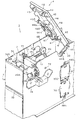
【図2】同じく、カバー本体を開放した状態の画像形成装置の要部の斜視図である。
【図3】同じく、(A)は上段の回転搬送体が水平方向にカードを順搬送する基準位置となる状態の要部の説明図、(B)は上段の回転搬送体から下段の回転搬送体へカードを渡す状態の要部の説明図、(C)は上段の回転搬送体が水平方向にカードを逆搬送する状態の要部の説明図、(D)は下段の回転搬送体から上段の回転搬送体へカードを渡す状態の要部の説明図である。
【図4】同じく、回転搬送体の回転位置検出センサーの検出タイミングを示すタイミング図である。
【図5】同じく、画像形成装置の処理を示すフロー図である。
【符号の説明】
C…カード
61…回転搬送体(第1の転回ユニット)
67…センサー
81…回転搬送体(第2の転回ユニット)
86…センサー
87…センサー[0001]
BACKGROUND OF THE INVENTION
The present invention relates to a card direction changing unit including a turning unit that changes the carrying direction of a card that has been carried in, and detection means having at least one detector that detects the rotational position of the turning unit.
[0002]
[Prior art]
Conventionally, for example, an image forming apparatus that prints a pattern or a character on a relatively thick and hard card such as a cash card, an employee card / membership card, or a prepaid card, for printing on both sides of the card and inputting a magnetic code In addition, there are known ones equipped with a turning unit for inverting and turning a card.
[0003]
As the rotation unit used in such an image forming apparatus, for example, as shown in Japanese Patent Application Laid-Open No. 9-131930, two upper and lower rotation units are rotated in synchronization with one drive means (pulse motor). It is also known that enables delivery of different transport routes.
[0004]
At this time, the rotating unit located in the upper stage is positioned at three positions at 90 degree intervals similarly to the rotating position detection plate that rotates integrally with the rotating unit and has three notches formed at 90 degree intervals. And a sensor for detecting notches at three locations on the rotational position detection plate in a rotating state, and by recognizing the position of the rotating part of the turning unit by a combination of the presence / absence detection of notches by these three sensors, the turning unit It detects the relative positions of the front and rear transport paths and the state of the front and back of the card.
[0005]
[Problems to be solved by the invention]
By the way, in the above-described turning unit, the rotation position of the upper and lower two-stage turning units is performed by a combination of three sensors provided in the upper-stage turning unit. When an assembling error occurs during assembling, there has been a problem that the upper and lower cards cannot be delivered and the card is jammed.
[0006]
Further, in such a turning unit, when rotating to pass the card from the upper stage to the lower stage and when rotating to pass the card from the lower stage to the upper stage, the card transport mechanism of each turning unit is non-electrically driven. In spite of the driving state, the card transport mechanism sends out the card due to the sliding contact rotation with the support shaft of the turning unit, which may cause the card jam.
[0007]
The present invention has been made in view of the above circumstances, and an object of the present invention is to provide a card direction changing unit that can perform good card transfer between turning units while having a simple and inexpensive configuration. .
[0008]
[Means for Solving the Problems]
In order to achieve the object, according to the first aspect of the present invention, a card is transferred between a first turning unit that changes the carrying direction of a card that has been carried in, and the first turning unit. A card turning unit comprising: a second turning unit that changes the driving unit; and one driving unit that drives each turning unit in synchronization.
A first detection means comprising one or more detectors for detecting the rotational position of the first turning unit, and a second detecting means comprising one or more detectors for detecting the rotational position of the second turning unit. And a detection means.
[0009]
According to a second aspect of the present invention, there is provided a direction determination unit that determines a rotation position of each of the rotation units based on a detection result of the first detection unit and a detection result of the second detection unit. The gist.
[0010]
According to a third aspect of the present invention, the direction determination unit includes a positioning unit that performs positioning using an edge signal of the first detection unit or the second detection unit, and the temporary determination is performed by the direction determination unit. After that, the gist is to perform the positive positioning by the positioning portion.
[0011]
The gist of the present invention is that a positioning portion for each of the detecting means is provided on a frame for fixing the conveying means for conveying the card.
[0012]
The gist of the invention described in
[0013]
The gist of the invention described in
[0014]
According to a seventh aspect of the present invention, each of the rotating units includes a rotating unit that synchronously drives the rotating units, a conveying unit that individually conveys a card in each of the rotating units, and the rotating unit. A transport driving unit that individually drives the transport unit independently of the unit; a determination unit that determines an error amount of the transport driving unit generated when the turning unit rotates based on information of the detection unit; The gist of the invention is that it includes a correction unit that drives in a direction to correct the error amount of the transport driving unit based on the determination result of the determination unit.
[0015]
The invention according to
A first rotating disk provided in the first turning unit and having detected portions formed at three positions at intervals of 90 degrees; and a first detector for detecting the detected portions of the first rotating disk; A second rotating disk that rotates in synchronization with the second rotating unit and that has three detected portions formed at three intervals at the same 90-degree intervals as the first rotating disk; and A second detector that detects the detected portion and is disposed opposite to the first detector; a third detector that is disposed 90 degrees apart from the second detector; and each of the detections And a direction determining unit that determines the rotational position of each of the rotating units based on a combination of detection results of the detected portion of the device.
[0016]
The invention according to claim 9 is characterized in that the first and second detectors detect each one of the convex portions of the first and second rotating disks and the third detector. The point is that the reference position of the first and second rotating disks is a state where none of the convex portions of the second rotating disk is detected.
[0017]
The gist of the invention described in
[0018]
The gist of the invention described in claim 11 is that each of the detectors is positioned with the turning unit side of the card passing side as a reference.
[0019]
The invention according to
Rotating to deliver a card from the first turning unit to the second turning unit and to deliver a card from the second turning unit to the first turning unit. The gist of the present invention is that the conveyance drive means corresponding to the conveyance means of the turning unit on the delivery side is reversely driven by a predetermined amount.
[0020]
The invention described in claim 13 is a first turning unit for changing the carrying direction of the card that has been carried in, and a second turning for changing the carrying direction of the card by handing over the card between the first turning unit. In an image forming apparatus comprising a unit and one driving unit that drives each of the rotating units synchronously,
The first bracket with the first turning unit, the second bracket with the second turning unit, and the brackets are positioned relative to each other when the brackets are attached to the apparatus body. The gist of the invention is that it includes positioning and fixing means for engaging with each bracket.
[0021]
According to a fourteenth aspect of the present invention, there is provided a first detecting means comprising one or more detectors for detecting a rotational position of the first turning unit, and a first detecting means for detecting the rotational position of the second turning unit. The gist of the present invention is that it comprises the second detection means comprising the above detector.
[0022]
DETAILED DESCRIPTION OF THE INVENTION
Next, an embodiment of the card direction changing unit of the present invention is applied to a sublimation type full color printer of an image forming apparatus and will be described based on the drawings.
[0023]
In FIG. 1, a sublimation type full-color printer 1 (hereinafter simply referred to as “
[0024]
The
[0025]
On one side wall of the cover
[0026]
Note that when the post-printing card C has no post-processing, a discharge tray (not shown) is provided below the
[0027]
As shown in FIG. 2, the lid 4 rotates about a
[0028]
The lid 4 is maintained in the closed state by engaging the
[0029]
The pressing
[0030]
The
[0031]
The
[0032]
The
[0033]
Further, the
[0034]
Further, the
[0035]
The
[0036]
The printing means 71 includes a
[0037]
The
[0038]
The
[0039]
The
[0040]
That is, in the state shown in FIG. 1, as shown in FIG. 3A, all of the
[0041]
In each of these states, the
[0042]
At this time, when the
[0043]
If this
[0044]
The direction determining unit detects edge signals from the
[0045]
For example, in the state shown by the position a in FIG. 4, the
[0046]
In addition, when the
In addition, a positioning unit that performs positioning using the above-described edge signal may be provided, and after the temporary positioning is performed by the direction determination unit, the positive positioning may be performed by the positioning unit.
[0047]
For example, when the
[0048]
On the other hand, the
[0049]
Therefore, when the
[0050]
In the above-described configuration, the unrecorded card C superimposed and placed on the
[0051]
As shown in FIG. 5, the card C introduced into the cover
[0052]
When the card C is a magnetic card, the card C on which an image has been recorded by the
[0053]
The card C for which magnetic recording has been completed is checked for the printing state in the
[0054]
[Brief description of the drawings]
FIG. 1 is a longitudinal sectional view of an image forming apparatus according to the present invention.
FIG. 2 is a perspective view of essential parts of the image forming apparatus in a state where a cover body is opened.
3A is an explanatory diagram of a main part in a state where the upper rotary transport body is a reference position for sequentially transporting cards in the horizontal direction, and FIG. 3B is a lower rotary transport from the upper rotary transport body. Explanatory drawing of the principal part of the state which passes a card | curd to a body, (C) is explanatory drawing of the principal part in the state which reversely conveys a card | curd in the upper stage rotation conveyance body, (D) is an upper stage from a lower rotation conveyance body. It is explanatory drawing of the principal part of the state which passes a card | curd to the rotary conveyance body of FIG.
FIG. 4 is a timing chart similarly showing detection timing of a rotational position detection sensor of the rotary conveyance body.
FIG. 5 is a flowchart showing processing of the image forming apparatus in the same manner.
[Explanation of symbols]
C ...
67 ...
86 ...
Claims (16)
前記第1の転回ユニットの回転位置を検出する1つ以上の検出器からなる第1の検出手段と、前記第2の転回ユニットの回転位置を検出する1つ以上の検出器からなる第2の検出手段とを備えていることを特徴とするカード方向転換ユニット。The first turning unit that changes the transport direction of the card that has been carried in, the second turning unit that transfers the card between the first turning unit and changes the transport direction of the card, and the respective turning units are synchronized. In the card direction changing unit provided with one drive means to be driven,
A first detection means comprising one or more detectors for detecting the rotational position of the first turning unit, and a second detecting means comprising one or more detectors for detecting the rotational position of the second turning unit. And a card direction changing unit.
前記第1の転回ユニットに設けられて90度間隔で3箇所に被検出部を形成した第1の回転円盤と、該第1の回転円盤の前記被検出部を検出する第1の検出器と、前記第2の転回ユニットと同期して回転すると共に前記第1の回転円盤と同一の90度間隔で3箇所に被検出部を形成した第2の回転円盤と、前記第2の回転円盤の被検出部を検出すると共に前記第1の検出器と対向配置された第2の検出器並びに該第2の検出器と90度間隔をおいて配置された第3の検出器と、前記各検出器の前記被検出部の検出結果の組み合わせによって前記各転回ユニットの回転位置を判断する方向判断部とを備えていることを特徴とするカード方向転換ユニット。The first turning unit that changes the transport direction of the card that has been carried in, the second turning unit that transfers the card between the first turning unit and changes the transport direction of the card, and the respective turning units are synchronized. In the card direction reversing unit provided with one driving means for driving
A first rotating disk provided in the first turning unit and having detected portions formed at three positions at intervals of 90 degrees; and a first detector for detecting the detected portions of the first rotating disk; A second rotating disk that rotates in synchronization with the second rotating unit and that has three detected portions formed at three intervals at the same 90-degree intervals as the first rotating disk; and A second detector that detects the detected portion and is disposed opposite to the first detector; a third detector that is disposed 90 degrees apart from the second detector; and each of the detections A card direction changing unit, comprising: a direction determining unit that determines a rotational position of each of the rotating units based on a combination of detection results of the detected portion of the card.
前記第1の転回ユニットから前記第2の転回ユニットへとカードを渡すために回転している際並びに前記第2の転回ユニットから前記第1の転回ユニットへとカードを受け渡すために回転している際には、その渡し側の転回ユニットの前記搬送手段に対応する前記搬送駆動手段が所定量逆転駆動することを特徴とするカード方向転換ユニット。The first turning unit that changes the transport direction of the card that has been carried in, the second turning unit that transfers the card between the first turning unit and changes the transport direction of the card, and the respective turning units are synchronized. A card direction reversing unit comprising: one driving means that is driven; a conveying means that conveys a card in each of the turning units; and a conveying driving means that drives the conveying means independently of the driving means .
Rotating to deliver a card from the first turning unit to the second turning unit and to deliver a card from the second turning unit to the first turning unit. The card direction changing unit is characterized in that the conveying driving means corresponding to the conveying means of the turning unit on the transfer side is reversely driven by a predetermined amount.
前記第1の転回ユニットを装着した第1のブラケットと、前記第2の転回ユニットを装着した第2のブラケットと、前記各ブラケットを装置本体に装着する際に前記各ブラケットを互いに位置決めするように前記各ブラケットに係合する位置決め固定手段を備えていることを特徴とする画像形成装置。The first turning unit that changes the transport direction of the card that has been carried in, the second turning unit that transfers the card between the first turning unit and changes the transport direction of the card, and the respective turning units are synchronized. In an image forming apparatus provided with one driving means to be driven
The first bracket with the first turning unit, the second bracket with the second turning unit, and the brackets are positioned relative to each other when the brackets are attached to the apparatus body. An image forming apparatus comprising positioning fixing means for engaging with each bracket.
Priority Applications (1)
| Application Number | Priority Date | Filing Date | Title |
|---|---|---|---|
| JP31153197A JP3820308B2 (en) | 1997-10-27 | 1997-10-27 | Card direction changing unit and image forming apparatus |
Applications Claiming Priority (1)
| Application Number | Priority Date | Filing Date | Title |
|---|---|---|---|
| JP31153197A JP3820308B2 (en) | 1997-10-27 | 1997-10-27 | Card direction changing unit and image forming apparatus |
Publications (2)
| Publication Number | Publication Date |
|---|---|
| JPH11134440A JPH11134440A (en) | 1999-05-21 |
| JP3820308B2 true JP3820308B2 (en) | 2006-09-13 |
Family
ID=18018367
Family Applications (1)
| Application Number | Title | Priority Date | Filing Date |
|---|---|---|---|
| JP31153197A Expired - Fee Related JP3820308B2 (en) | 1997-10-27 | 1997-10-27 | Card direction changing unit and image forming apparatus |
Country Status (1)
| Country | Link |
|---|---|
| JP (1) | JP3820308B2 (en) |
Families Citing this family (1)
| Publication number | Priority date | Publication date | Assignee | Title |
|---|---|---|---|---|
| CN104827784A (en) * | 2015-04-14 | 2015-08-12 | 南京华桠融通智能科技有限公司 | Smart card overturning module |
-
1997
- 1997-10-27 JP JP31153197A patent/JP3820308B2/en not_active Expired - Fee Related
Also Published As
| Publication number | Publication date |
|---|---|
| JPH11134440A (en) | 1999-05-21 |
Similar Documents
| Publication | Publication Date | Title |
|---|---|---|
| JP3346922B2 (en) | Card reversing device for card printer | |
| US5959278A (en) | Information card producing device | |
| JP3620362B2 (en) | Card recorder | |
| US4463939A (en) | Slip issuing device | |
| JP3820308B2 (en) | Card direction changing unit and image forming apparatus | |
| JP3625206B2 (en) | Card recorder | |
| JPH11147348A (en) | Opening/closing mechanism for cover | |
| JP3547598B2 (en) | Recording device | |
| JP3725062B2 (en) | Magnetic recording device | |
| JPH11120298A (en) | Device and method for supplying card | |
| JP2000052578A (en) | Thermal transfer recorder | |
| JP3745293B2 (en) | Recording device | |
| JP3722432B2 (en) | Information recording device | |
| JP3299360B2 (en) | Transport path switching device | |
| JPH11151824A (en) | Image forming apparatus | |
| JP3505524B2 (en) | Recording device | |
| JPH1148557A (en) | Image forming equipment | |
| JPS6271674A (en) | Recorder | |
| JP2710293B2 (en) | Transport device for passbook printer | |
| JP2570854B2 (en) | Recording device | |
| JP2548551B2 (en) | Recording device | |
| JPH09150983A (en) | Recording device | |
| US20130087966A1 (en) | Sheet-shaped medium feeding device and sheet-shaped medium processing device | |
| JPH0531981A (en) | Device for issue of card | |
| JP2020155077A (en) | Information recording device, recording medium supply device and image formation device |
Legal Events
| Date | Code | Title | Description |
|---|---|---|---|
| A621 | Written request for application examination |
Free format text: JAPANESE INTERMEDIATE CODE: A621 Effective date: 20041019 |
|
| A977 | Report on retrieval |
Free format text: JAPANESE INTERMEDIATE CODE: A971007 Effective date: 20051212 |
|
| A131 | Notification of reasons for refusal |
Free format text: JAPANESE INTERMEDIATE CODE: A131 Effective date: 20060124 |
|
| A521 | Written amendment |
Free format text: JAPANESE INTERMEDIATE CODE: A523 Effective date: 20060207 |
|
| A521 | Written amendment |
Free format text: JAPANESE INTERMEDIATE CODE: A821 Effective date: 20060207 |
|
| TRDD | Decision of grant or rejection written | ||
| A01 | Written decision to grant a patent or to grant a registration (utility model) |
Free format text: JAPANESE INTERMEDIATE CODE: A01 Effective date: 20060523 |
|
| A61 | First payment of annual fees (during grant procedure) |
Free format text: JAPANESE INTERMEDIATE CODE: A61 Effective date: 20060619 |
|
| R150 | Certificate of patent or registration of utility model |
Free format text: JAPANESE INTERMEDIATE CODE: R150 |
|
| FPAY | Renewal fee payment (event date is renewal date of database) |
Free format text: PAYMENT UNTIL: 20100623 Year of fee payment: 4 |
|
| FPAY | Renewal fee payment (event date is renewal date of database) |
Free format text: PAYMENT UNTIL: 20110623 Year of fee payment: 5 |
|
| FPAY | Renewal fee payment (event date is renewal date of database) |
Free format text: PAYMENT UNTIL: 20110623 Year of fee payment: 5 |
|
| FPAY | Renewal fee payment (event date is renewal date of database) |
Free format text: PAYMENT UNTIL: 20120623 Year of fee payment: 6 |
|
| FPAY | Renewal fee payment (event date is renewal date of database) |
Free format text: PAYMENT UNTIL: 20130623 Year of fee payment: 7 |
|
| R250 | Receipt of annual fees |
Free format text: JAPANESE INTERMEDIATE CODE: R250 |
|
| R250 | Receipt of annual fees |
Free format text: JAPANESE INTERMEDIATE CODE: R250 |
|
| R250 | Receipt of annual fees |
Free format text: JAPANESE INTERMEDIATE CODE: R250 |
|
| LAPS | Cancellation because of no payment of annual fees |