JP3819552B2 - Stainless steel mesh joining method and stainless steel mesh joined at both ends - Google Patents
Stainless steel mesh joining method and stainless steel mesh joined at both ends Download PDFInfo
- Publication number
- JP3819552B2 JP3819552B2 JP21378797A JP21378797A JP3819552B2 JP 3819552 B2 JP3819552 B2 JP 3819552B2 JP 21378797 A JP21378797 A JP 21378797A JP 21378797 A JP21378797 A JP 21378797A JP 3819552 B2 JP3819552 B2 JP 3819552B2
- Authority
- JP
- Japan
- Prior art keywords
- stainless steel
- welding
- line
- meridian
- joining
- Prior art date
- Legal status (The legal status is an assumption and is not a legal conclusion. Google has not performed a legal analysis and makes no representation as to the accuracy of the status listed.)
- Expired - Lifetime
Links
Images


Landscapes
- Paper (AREA)
Description
【0001】
【発明の属する技術分野】
本発明は、ステンレス金網を溶接によって接合する方法及び接合したステンレス金網に関する。
【0002】
【従来の技術】
従来より、製紙用金網を溶接によって接合して無端状に形成することはよく行われている。ステンレス金網は特に製紙用に多く使用されており、この用途のステンレス金網は溶接により無端状とされていた。
例えば、金ろうや銀ろう等のろう材を使用した溶接である。
しかし、ろう材を使用して溶接すると、金網を構成している線材とろう材との間に電位差が生じて線材とろう材とのどちらかが腐食する電食が発生して使用中や保管中に溶接した接合部が切断する問題があった。
また、製紙用金網は腐食環境下で使用されることが多いために、腐食に強いステンレス線材を使用するが、ろう材の耐食性がステンレスの耐食性より小さいのでステンレスの優れた耐腐蝕性を十分に生かすことができないというのが現状である。
上記の電食を発生させない方法として、ろう材を使用せずに金網を構成している線材自体を突き合わせたり、重ね合わせたりして接触させて、その部分を溶融して同一ステンレス材で溶接する方法が提案された。
この方法は溶接接合部が全て同金属であるため電位差が生じることがなく、電食によって接合部が切断することがない。
したがって、線材にステンレスを使用した場合にもステンレスの優れた耐腐蝕性を生かすことが可能となる。しかし、この方法には次のような欠点があった。最大の欠点は溶接接合部が太くなって段差が発生したり、目の開きが変わってしまうことである。それによって、表面性やろ水性が変わり、抄造する紙にマークを発生させる等の悪影響を生ずるが、この問題は製紙用金網としては極めて重大な欠点である。
溶接後にコロがけをして、できるだけ平坦にする努力もされてもいるが完全に修正できるものではない。したがって、特に表面性を重視されるものや細かいメッシュの製紙用金網には採用できなかった。また、粗い網に採用したとしても、細かい網をその上に重ねて使用する場合には、前述のように一部形状が異なるために、細かい網を切断させてしまうという問題があった。
また、溶接作業に大変な手間がかかるという問題もあった。
この線材自体を溶かして溶接する方法には溶接部を水平に突き合わせる方法、上下に重ね合わせる方法、傾斜して起立した端部をいわゆるおがみ合わせて突き合わせる方法、横方向に接触させる方法等がある。
【0003】
これ等のどの方法にしても、溶接する線材同士を確実に接触させ、かつ、接触させている方向にある程度の力を加えておかなくてはならない。
力を加えておかなければ、両端の溶接する線材の接触部がそれぞれ溶けるのみで、溶けた部分が一体化されず、接合されないからである。
したがって、溶接する線材1本1本をピンセット等を用いて位置合せして確実に接触させなくてはならず、溶接の前工程に大変な手間がかかっていた。また、いくら位置合わせをするといっても、溶接する巾全ての線材を接触させ、かつ、力を加えておくことはほとんど不可能であって、せいぜい数センチの巾でしかできなかった。したがって、連続して溶接できる巾もこの巾に限られてしまい、少し溶接して位置合わせをし、また少し溶接して位置合わせをするという作業の繰返で連続作業ができなかった。
特に、円網抄紙機に用いられる円網の平行四辺形に切断した製紙用金網を、線が円筒軸方向と傾斜して溶接接合部が螺旋状に形成されるように円筒状に接合する、いわゆるダイヤゴナル溶接では、作業が極めて困難であった。
このダイヤゴナル溶接では、寸法的な問題からほとんどの場合製織時の緯線を突き合わせて溶接するが、突き合わせて溶接する緯線は溶接部では同じ緯線ではなく、経線方向にずれた異なる緯線である。製織時に緯線のメッシュを正確に一定のメッシュで製織することは困難であって、場所によってメッシュが微妙に異なっているために突き合わせたときにズレが生じ、その位置合わせには大きな手間、労力、時間が必要であって、コストアップの一つの要因になっていた。
また、溶接時に加熱面の裏側は熱が伝わり難くて、溶けにくいために溶接強度が弱くなるという問題もあった。
【0004】
【発明が解決しようとする課題】
本発明は、上述の従来技術の問題を鑑みて、溶接接合部が電食によって切断することがなく、なおかつ、容易に溶接作業が行える製紙用金網の溶接接合方法を提供するものである。
【0005】
【問題を解決するための手段】
本発明は、
「1. 製織されたステンレス金網を溶接によって接合する製紙用ステンレス金網の接合方法において、接合する端部の少なくとも一方を、端部に沿った巾方向の線(以下緯線とし、端部と直交する方向の線を経線とする)が存在するように形成した後、接合する両端部を緯線の一部または全部と経線とを以って突き合わせ部を形成し、突き合わせ部にはステンレス材以外の物を存在させず、経線が下側の裏面に位置し、その上に緯線が位置している部分ではまず緯線が溶けて経線の突き合わせ部近傍に回り込むとほぼ同時に経線と溶け合って一体化され、また経線が上側の表面に位置し、その下に緯線が位置している部分では経線が上から溶けるとほぼ同時に、徐々に溶けてきた緯線が経線の下の部分に向かって回り込んで経線と溶け合って一体化され、同一のステンレス素材からなる溶接部を形成することを特徴とする、ステンレス金網の接合方法。
2. 突き合わせ部の接合する両端部の長さ方向の線の綾を合わせて突き合わせた、請求項1に記載されたステンレス金網の接合方法。
3. 突き合わせ部が両端の巾方向の線を線径が約1/2になるまで削って形成した突き合わせ部である、請求項1または2に記載されたステンレス金網の接合方法。
4. 突き合わせ部が両端の突き合わせ部の巾方向の線を線径が約1/2になるまで削ってその間に同一のステンレス素材の溶接補助片を配置した突き合わせ部である、請求項1ないし3のいずれか1項に記載されたステンレス金網の接合方法。
5. 突き合わせ部の溶接方法がプラズマ溶接である、請求項1ないし4のいずれか1項に記載されたステンレス金網の接合方法。
6. 接合する端部の一方には巾方向の線の一部または全部と長さ方向の線とを以て突き合わせ部を形成し、他方には長さ方向の線で突き合わせ部を形成し、両突き合わせ部を突き合わせて溶接し同一のステンレス素材からなる溶接部を形成することを特徴とするステンレス金網の接合方法。
7. 請求項1ないし6のいずれか1項に記載されたステンレス金網の接合方法により両端部を接合したステンレス金網。」
に関する。
【0006】
【発明の実施の形態】
本発明で使用されるステンレス線としては単線、より線等が使用される。また、織組織の平織、各種綾織、朱子織り、朱子織りの一重織りや多重織組織も使用できて特に限定されない。ステンレスの線材としては、SUS304、SUS316、SUS317等が好適に用いられる。
本発明の特徴は、金網を構成している線材自体を溶かして溶接することである。溶接接合部が全て同一のステンレスであるため電位差が生じることがなく、電食によって接合部が切断することがない。
本発明の他の特徴は、接合する端部の少なくとも一方を、端部に沿った巾方向の線が存在するように形成した後、該両端部を突き合わせ、突き合わせ部を溶接して両端部を接合したことである。
ここで、説明の都合上、端部に沿った巾方向の線を緯線とし、端部と直交する方向の線を経線と言う。
従来のように単に経線を突き合わせただけでなく、突き合わせ部に経線と密着して織り合わされている緯線が介在しているため、溶接時にこの緯線が溶けて、経線の突き合わせ部の上下に回り込んで溶接されるのである。
【0007】
さらに詳しく説明すると、織物の綾の関係で経線が下側の裏面に位置し、その上に緯線が位置している部分では、まず緯線が溶けて経線の突き合わせ部近傍に回り込むとほぼ同時に経線と溶け合って一体化される。
一方、経線が上側の表面に位置し、その下に緯線が位置している部分では、経線が上から溶けるとほぼ同時に、徐々に溶けてきた緯線が経線の下の部分に向かって回り込んで経線と溶け合って一体化するのである。
また、本発明では、接合する両端部を綾を合わせて突き合わせることにより、経線を緯線の上に位置する経線同士、緯線の下に位置する経線同士を溶接させることができ、溶接部を網の他の部分とほぼ同じ形状に形成させることもできる。
さらに本発明では、接合する両端部を、端部の緯線を線径が1/2程度になるまで削って形成することにより、溶接時に経線の突き合わせ部の両側にバランスよく緯線が溶けて回り込み、経線が溶接されると同時に両端部の緯線を左右対象に他の緯線とほぼ同線径に一体化させることもできる。
【0008】
また、突き合わせ部の端部間に、薄板状に形成した製紙用金網と同材質、または近似材質の溶接補助片を配置することもできる。
溶接補助片は、例えば突き合わせた経線にずれが生じる場合に効果的である。
経線にズレが生じると、その部分において、介在する緯線だけでは、緯線を残すためにはステンレスが量的に不足してしまう場合がある。溶接補助片はその不足分を補う補助として働くのである。
勿論、これに限定されるわけではなく、端部に緯線が介在していればよいのであって、例えば、両端部を削った後、片側の緯線を除去して、片側のみに緯線を介在させて溶接し、溶接時に介在させた緯線を経線と一体化させるようにすることもできるのである。
この場合、緯線がなくなってしまうため溶接部に目開きが発生してしまう欠点はあるが、経線間の緯線を残さなくてよいので、前述した緯線を残す場合と比較してよりラフに溶接を行える利点がある。目開きや、マークの発生をあまり問題にしない用途の場合には好適である。
溶接法の種類としても、特に限定されるわけではなく、色々な溶接法が採用できるが、中でもプラズマ溶接が周囲に熱影響をあまり及ぼさず、レーザー溶接よりも強度が得られるため好ましい。本発明の接合方法により両端を接合したステンレス金網は製紙用網やコンベアに使用される。
【0009】
【実施例】
発明の実施の形態を実施例に基づいて図面を参照して説明する。
図1は、本発明の一実施例である溶接方法を示す平面図である。
本実施例では、両端部の端部に沿った巾方向の緯線3を線径が半分程度になるまで削った後、この両端部を、端部と直交する方向の経線1どうしが接して向き合うように綾を合わせて突き合わせ、突き合わせ部を溶接して両端部を接合する。
1が経線であり、2が緯線である。
まず、はさみ等で緯線に沿って網を切断し、さらに端部をやすり等で端部に沿った巾方向の緯線3を線径が半分程度になるまで削る。
次に、両端部を経線1どうしが接して向き合うように綾を合わせて突き合わせる。
綾を合わせたことによって、端部の削って形成した緯線3の上に位置する経線どうし、端部の削って形成した緯線3の下に位置する経線どうしが向き合って接していることがよく理解される。
使用したステンレス網は経線と緯線に線径0.5mmのSUS316ステンレス線を用いて製織した10メッシュの平織組織の網である。
溶接は溶接部にアルゴンガスを吹き付け、アルゴンシールドを行ってプラズマ溶接を行った。
本実施例では、端部の緯線を削って形成したが、本発明はこれに限定されるわけではなく、端部に緯線が介在すればよいので、網を緯線ぎりぎりにはさみ等で切断して端部を形成しただけでもよい。
しかし、削って形成した方が経線の最端部に緯線が確実に密着できるため、溶けた緯線の経線端部への回り込みが良好で好ましいのである。
また、接合する両端部を、端部の緯線を線径が半分程度になるまで削って形成した方が、溶接時に経線の突き合わせ部の両側にバランスよく緯線が溶けて回り込むため、両端部の溶接部が左右対象になり他の緯線とほぼ同線径に一体化させることもできるため好ましい。
また、本実施例では突き合わせ部の端部間に、板状に形成した製紙用金網と同材質の溶接補助片4を配置した。
溶接補助片4は絶対に必要というわけではないが、例えば突き合わせた経線の突き合わせにずれが生じる場合に効果的である。
経線にズレが生じると、その部分において、介在する緯線だけでは、緯線を残すためには量的に不足してしまう。溶接補助片はその不足分を補う補助として働くためである。
また、緯線を削る量や、溶接補助片の大きさを変更することにより、溶接後の溶接部の緯線の太さや、目開きを調節することができる。
また、本実施例では綾を合わせて突き合わせたが、本発明ではこれに限定されるわけではない。
突き合わせた経線の綾がずれて、正確に接触しなくても問題なく溶接はできる。さらには、綾などは無視して、ただ単に突き合わせたのみでもよく、端部の緯線が橋渡しの役割をするため溶接が可能である。ステンレス網の用途によっては溶接部の多少の乱れは支障がない場合もあるからである。
綾を正確に合わせることができれば最も好ましいが、そのためには、網のメッシュが正確に一致していなければならず、実質的には困難な場合もある。
前述したようにダイヤコナル継ぎではズレが生じる可能性が大きい。
【0010】
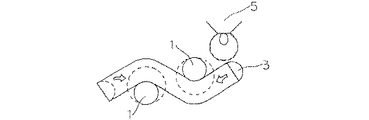
図2は、図1のA−A線で切断した断面図である。経線1と端部の削って形成した緯線3が交点で密着していることがわかる。
5が溶接機のトーチであり、図面右側から左に向かって移動しながら溶接していく。トーチ5の移動にともなって緯線3が徐々に溶けていく。経線1と緯線3の交点の部分では、トーチ5が直接経線1を溶かすことに加え、溶けた緯線3が経線1、1′を包み込むように回り込んで、経線1と緯線3を一体化させるのである。
図に示した点線部は溶接後、溶け合って一体化した部分を示している。
矢印は緯線3が溶け出す方向を示している。
緯線3が経線1、1′の下側にも回り込んで完全に一体化しているのがわかる。
緯線3が経線1、1′の間に介在しているため、従来の経線単独の場合と異なり、経線の先端部分が玉状の溶けてマッチ棒のようになることはないので、突き合わせた方向の押し合わせて一体化させる必要がなく、軽く接触させる程度で良好に溶接できるのである。
【0011】
図3は、図1のB−B線で切断した断面図であり、図4は図1のC−C線で切断した断面図である。
緯線3が線径の半分程度まで削り込まれて形成されており、突き合わせ部間には板状の溶接補助片4が配置されている。
図5は、別の実施例である溶接方法を示す平面図である。
両端部を削った後、片側のみの端部に沿った方向の削った緯線3を除去して溶接した場合であって、突き合わせた経線1のメッシュが巾方向にズレている場合である。
【0012】
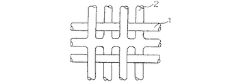
図6が溶接後の状態を示す平面図である。6が溶接部である。
経線1にズレが生じていても、半分の径に削られた緯線3が橋渡しの役割をするため、溶接が可能である。また、メッシュが多少ズレても、図示したように1本の経線と2本の経線を溶接させることもでき、その部分で経線の突き合わせのズレを解消させることができるのである。従来このように溶接する場合は、ピンセット等で1本の経線と2本の経線を完全に接触するように位置合わせをしていたのである。
図5に示す実施例の場合は、溶接後緯線がなくなるために、溶接部に目開きが生ずるが、緯線3を溶かして図6に示すように溶接部6に集約させればよく、緯線3を残さなくてもよいため、図1〜図3の実施例よりもさらにラフに溶接を行える利点がある。
【0013】
比較試験
次に、ただ単に経線を突き合わせる従来の方法と図1に示した実施例とで、溶接スピードと溶接後の状態を比較した。
図7が実施例1の溶接部を示す平面図であり、図8が従来例の溶接部を示す平面図である。
溶接した金網は経線、緯線に0.5mmのステンレス線を用いて製織した10メッシュの平織組織である。
溶接は、溶接部にアルゴンガスを吹き付け、アルゴンシールドを行いつつプラズマ溶接で溶接した。
従来例の場合は経線を突き合わせ押し合わせて溶接しているために溶接部が玉状に太くなって、大きな凹凸が発生し、目開きも生じている。
実施例1の場合は、経線と緯線の交差部分が多少太くなってはいるが、凹凸の発生もほとんどなく、目開きの発生もなく、他の部分とほぼ同じ状態に形成されている。
また、従来例では、位置合わせをして少し溶接してまた位置合わせをするという作業の繰り返しであるため、2mの巾を溶接するのに1時間以上の溶接時間が必要であったが、実施例では15分であった。
【0014】
【発明の効果】
本発明は、以上説明したように同一のステンレスを溶接しろう材を使用しないため、溶接接合部が電食によって切断することがない。
また、端部に緯線を介在させているために、容易に、長い巾を連続して溶接が可能であって、溶接部を他の部分とほとんど変わらない状態に形成させることもできる。
また、経線が完全に向き合って付き合わされてなくメッシュがずれていても容易に溶接させることができる効果が奏される。
【図面の簡単な説明】
【図1】本発明の一実施例である溶接方法を示す平面図である。
【図2】図1のA−A線で切断した断面図である。
【図3】図1のB−B線で切断した断面図である。
【図4】図1のC−C線で切断した断面図である。
【図5】別の実施例である溶接方法を示す平面図である。
【図6】図5の溶接後の状態を示す平面図である。
【図7】実施例の溶接部を示す平面図である。
【図8】従来例の溶接部を示す平面図である。
【符号の説明】
1 経線
2 緯線
3 端部の削って形成した緯線
4 溶接補助片
5 トーチ
6 溶接部[0001]
BACKGROUND OF THE INVENTION
The present invention relates to a method for joining stainless wire mesh by welding and the joined stainless wire mesh.
[0002]
[Prior art]
2. Description of the Related Art Conventionally, it has been common practice to form a papermaking wire mesh by welding to form an endless shape. Stainless wire mesh is often used especially for papermaking, and the stainless wire mesh for this purpose is made endless by welding.
For example, welding using a brazing material such as gold brazing or silver brazing.
However, if welding is performed using brazing material, there is a potential difference between the wire and the brazing material that make up the wire mesh, resulting in galvanic corrosion that corrodes either the wire or brazing material. There was a problem that the welded joint was cut.
In addition, because the wire mesh for papermaking is often used in corrosive environments, stainless steel wires that are resistant to corrosion are used, but the corrosion resistance of the brazing material is smaller than that of stainless steel, so the excellent corrosion resistance of stainless steel is sufficient. The current situation is that it cannot be used.
As a method of preventing the occurrence of electric corrosion, the wire itself constituting the wire mesh itself is brought into contact with each other without being brazed, or is overlapped and contacted, and the part is melted and welded with the same stainless steel material. A method was proposed.
In this method, since all the welded joints are made of the same metal, a potential difference does not occur, and the joints are not cut by electrolytic corrosion.
Therefore, even when stainless steel is used for the wire, it is possible to take advantage of the excellent corrosion resistance of stainless steel. However, this method has the following drawbacks. The biggest drawback is that the welded joint becomes thicker, resulting in steps, and changing the opening of the eyes. As a result, the surface properties and the water drainage are changed, and an adverse effect such as generation of a mark on the paper to be produced is caused. However, this problem is a very serious defect for a papermaking wire mesh.
Efforts have been made to roll the surface after welding to make it as flat as possible, but this cannot be completely corrected. Therefore, it could not be used for paper meshes with particular emphasis on surface properties and fine mesh papermaking. Moreover, even if it is adopted as a coarse mesh, when a fine mesh is used on top of it, there is a problem that the fine mesh is cut because a part of the shape is different as described above.
In addition, there is a problem that the welding work takes a lot of time.
The method of melting and welding the wire itself includes a method of butting the welded portion horizontally, a method of overlapping the top and bottom, a method of facing the inclined and standing end portion, a method of making a contact in the lateral direction, etc. is there.
[0003]
In any of these methods, the wires to be welded must be reliably brought into contact with each other and a certain amount of force must be applied in the contacting direction.
If no force is applied, the contact portions of the wire to be welded at both ends only melt, and the melted portions are not integrated and are not joined.
Therefore, each wire to be welded must be aligned using tweezers and the like to be surely brought into contact with each other, which takes a lot of labor in the pre-welding process. Moreover, no matter how much the alignment is performed, it is almost impossible to bring all the wire rods to be welded into contact with each other and to apply a force. Therefore, the width that can be continuously welded is also limited to this width, and the continuous operation cannot be performed by repeating the operations of welding a little and aligning the position, and aligning the position by welding a little.
In particular, a papermaking wire mesh cut into a parallelogram of a circular mesh used in a circular mesh paper machine is joined in a cylindrical shape so that a weld is formed in a spiral shape with a line inclined with respect to the cylindrical axial direction. With so-called diagonal welding, the operation was extremely difficult.
In this diagonal welding, in most cases, welding is performed by butting the parallels at the time of weaving due to dimensional problems. However, the parallels to be welded by butt welding are not the same latitude line but a different latitude line shifted in the meridian direction. When weaving, it is difficult to weave the mesh of the latitude line with a precise constant mesh, and the mesh is slightly different depending on the location, so there is a deviation when matching, and the positioning is a great effort, labor, Time was required, which was one factor in increasing costs.
Further, there is also a problem that the welding strength is weak because the back side of the heating surface is difficult to transfer heat and hardly melts during welding.
[0004]
[Problems to be solved by the invention]
In view of the above-described problems of the prior art, the present invention provides a welded joining method for a papermaking wire mesh in which a welded joint is not cut by electrolytic corrosion and can be easily welded.
[0005]
[Means for solving problems]
The present invention
“1. In a joining method of a stainless steel mesh for papermaking in which a woven stainless steel mesh is joined by welding , at least one of the joined end portions is a line in the width direction along the end portion (hereinafter referred to as a latitude line and orthogonal to the end portion). A butt line is formed with a part or all of a latitude line and a meridian at both ends to be joined, and the butt part is made of a material other than stainless steel. In the part where the meridian is located on the lower back surface and the latitude line is located above it, the latitude line first melts and wraps around the butt portion of the meridian, and at the same time, merges with the meridian and is integrated. At the point where the meridian is located on the upper surface and the latitude line is below it, the meridian melts from above, and at the same time, the gradually melting latitude line turns toward the lower part of the meridian and merges with the meridian The A method for joining stainless steel wire mesh, characterized in that a welded portion made of the same stainless steel material is formed integrally .
2. The joining method of the stainless steel wire mesh according to claim 1, wherein the twills of the lines in the length direction of both end portions to which the butt portions are joined are matched.
3. The joining method of the stainless steel wire mesh according to claim 1 or 2, wherein the butted portion is a butted portion formed by cutting a widthwise line at both ends until the wire diameter becomes approximately ½.
4). The butt portion is a butt portion in which a wire in the width direction of the butt portion at both ends is cut until the wire diameter becomes approximately ½, and a welding auxiliary piece of the same stainless steel material is disposed therebetween. 2. A method for joining stainless steel wire meshes according to item 1.
5). The method for joining stainless steel wire mesh according to any one of claims 1 to 4, wherein the welding method of the butted portion is plasma welding.
6). One end of the joint is formed with a part or all of the line in the width direction and the line in the length direction, and the other is formed with a butt part with the line in the length direction. A method for joining stainless steel wire meshes, characterized in that a welded portion made of the same stainless steel material is formed by butt welding.
7). A stainless steel wire mesh having both ends joined by the method for joining stainless steel wire meshes according to any one of claims 1 to 6. "
About.
[0006]
DETAILED DESCRIPTION OF THE INVENTION
As the stainless steel wire used in the present invention, a single wire, a stranded wire or the like is used. In addition, a plain weave, various twills, satin weave, satin weave, single weave or multiple weave can be used, and there is no particular limitation. As the stainless steel wire, SUS304, SUS316, SUS317, or the like is preferably used.
The feature of the present invention is to melt and weld the wire itself constituting the wire mesh. Since all the welded joints are made of the same stainless steel, there is no potential difference and the joints are not cut by electrolytic corrosion.
Another feature of the present invention is that at least one of the end portions to be joined is formed so that there is a line in the width direction along the end portion, the both end portions are butted, the butted portions are welded, and the both end portions are welded. It is joining.
Here, for convenience of explanation, a line in the width direction along the end portion is referred to as a latitude line, and a line in a direction orthogonal to the end portion is referred to as a meridian.
In addition to just abutting meridians as in the past, since the wefts that are in close contact with the meridians are intervened at the abutment, the latitudes melt during welding and wrap around the meridian abutment It is welded by.
[0007]
More specifically, the meridian is located on the lower back surface due to the twill of the fabric, and in the portion where the latitude line is located above, the meridian first melts and wraps around the abutting portion of the meridian and almost simultaneously They are fused and integrated.
On the other hand, in the part where the meridian is located on the upper surface and the latitude line is located below it, the meridian gradually melted toward the lower part of the meridian almost simultaneously with the melting of the meridian from above. It melts and merges with the meridians.
Further, in the present invention, by joining the both end portions to be joined together with a twill, the meridians can be welded between meridians located above the latitude lines and the meridians located below the latitude lines. It can also be formed in substantially the same shape as the other parts.
Furthermore, in the present invention, by forming both end portions to be joined by cutting the latitude line of the end portion until the wire diameter becomes about ½, the latitude line melts and wraps around on both sides of the butt portion of the meridian during welding, At the same time as the meridian is welded, the latitude lines at both ends can be integrated with the left and right objects so as to have the same diameter as the other latitude lines.
[0008]
In addition, a welding auxiliary piece made of the same material as or a similar material to the paper-making wire mesh formed in a thin plate shape can be disposed between the end portions of the abutting portion.
The welding auxiliary piece is effective when, for example, a deviation occurs in the abutted meridians.
When the meridian is misaligned, there may be a shortage of the amount of stainless steel in order to leave the latitude line only at the intervening latitude line. The welding aid piece serves as an aid to compensate for the shortage.
Of course, the present invention is not limited to this, and it is only necessary to have a latitude line at the end. For example, after removing both ends, the latitude line on one side is removed, and the latitude line is interposed only on one side. It is also possible to integrate the latitude lines intervened during welding with the meridians.
In this case, there is a drawback in that the weld line is not open because the latitude line is lost, but it is not necessary to leave a parallel line between meridians, so welding is rougher than when leaving the latitude line described above. There is an advantage that can be done. This is suitable for applications where the opening of the marks and the occurrence of marks are not a significant problem.
The type of welding method is not particularly limited, and various welding methods can be adopted. Among them, plasma welding is preferable because it does not exert much thermal influence on the surroundings and can provide strength more than laser welding. The stainless steel wire mesh joined at both ends by the joining method of the present invention is used for a papermaking mesh or a conveyor.
[0009]
【Example】
DESCRIPTION OF THE PREFERRED EMBODIMENTS Embodiments of the present invention will be described based on examples with reference to the drawings.
FIG. 1 is a plan view showing a welding method according to an embodiment of the present invention.
In this embodiment, after cutting the
1 is a meridian and 2 is a latitude line.
First, the net is cut along the latitude line with scissors or the like, and further, the edge in the
Next, the twills are aligned and abutted so that the two meridians 1 are in contact with each other and face each other.
By aligning the twill, it is well understood that the meridians located above the
The stainless steel mesh used was a 10 mesh plain weave mesh woven with SUS316 stainless steel wire having a wire diameter of 0.5 mm for meridians and latitudes.
For welding, argon gas was sprayed on the welded portion, and argon welding was performed to perform plasma welding.
In the present embodiment, the latitude line at the end is cut and formed. However, the present invention is not limited to this, and it is sufficient that the latitude line is interposed at the end, so that the net is cut with scissors or the like. Only the end portions may be formed.
However, it is preferable to cut and form the latitude line so that the latitude line can be in close contact with the end of the meridian.
In addition, when both ends to be joined are formed by cutting the parallels at the end until the wire diameter is reduced to about half, the parallels melt around both sides of the meridian butt when welding, so both ends are welded. This is preferable because the portion becomes the left and right object and can be integrated with the other latitude lines so as to have almost the same diameter.
Further, in this embodiment, a welding
Although the
When the meridian is misaligned, the intervening latitude line alone is insufficient in quantity to leave the latitude line. This is because the welding auxiliary piece works as an auxiliary to compensate for the shortage.
Moreover, the thickness of the latitude line of a welding part after welding and an opening can be adjusted by changing the amount of cutting a latitude line and the size of a welding auxiliary piece.
Further, in the present embodiment, the twills are matched but are not limited to this in the present invention.
The warps of the warped meridians are misaligned and welding can be performed without any problem even if they do not contact accurately. Furthermore, the twill and the like are ignored, and they may simply be brought into contact with each other. Since the parallels at the ends serve as a bridge, welding is possible. This is because, depending on the use of the stainless steel mesh, some disturbance of the welded portion may not be hindered.
Although it is most preferable if the twill can be accurately aligned, for this purpose, the meshes of the mesh must be accurately matched, which may be substantially difficult.
As described above, there is a high possibility of deviation in the diamond-conal joint.
[0010]
2 is a cross-sectional view taken along line AA in FIG. It can be seen that the meridian 1 and the
Reference numeral 5 denotes a torch of a welding machine, which performs welding while moving from the right side to the left side of the drawing. As the torch 5 moves, the
The dotted line part shown in the figure shows the part that is fused and integrated after welding.
The arrow indicates the direction in which the
It can be seen that the
Since the
[0011]
3 is a cross-sectional view taken along line BB in FIG. 1, and FIG. 4 is a cross-sectional view taken along line CC in FIG.
The
FIG. 5 is a plan view showing a welding method according to another embodiment.
This is a case where after cutting both ends, welding is performed by removing the
[0012]
FIG. 6 is a plan view showing a state after welding. 6 is a welding part.
Even if the meridian 1 is misaligned, the
In the case of the embodiment shown in FIG. 5, since the latitude line after welding disappears, the welded portion is opened. However, the
[0013]
Comparative Test Next, the welding speed and the state after welding were compared between the conventional method of simply matching the meridians and the embodiment shown in FIG.
FIG. 7 is a plan view showing the welded portion of Example 1, and FIG. 8 is a plan view showing the welded portion of the conventional example.
The welded wire mesh is a 10-mesh plain weave structure woven using 0.5 mm stainless wire for meridians and latitudes.
Welding was performed by plasma welding while blowing argon gas to the weld and performing argon shielding.
In the case of the conventional example, since the meridians are pressed against each other and welded, the welded portion becomes thick in a ball shape, large irregularities are generated, and openings are also generated.
In the case of Example 1, the intersecting portion of the meridian and the latitude line is somewhat thick, but there is almost no unevenness, no mesh opening, and it is formed in almost the same state as the other portions.
Moreover, in the conventional example, since the operation of positioning, welding a little, and positioning is repeated, welding time of 1 hour or more was required to weld a width of 2 m. In the example it was 15 minutes.
[0014]
【The invention's effect】
In the present invention, since the same stainless steel is welded and no brazing material is used as described above, the welded joint is not cut by electrolytic corrosion.
Further, since the latitude line is interposed at the end portion, it is possible to easily weld a long width continuously, and the welded portion can be formed in a state almost unchanged from other portions.
Further, there is an effect that the meridians can be easily welded even when the meridians are not completely faced to each other and the meshes are shifted.
[Brief description of the drawings]
FIG. 1 is a plan view showing a welding method according to an embodiment of the present invention.
FIG. 2 is a cross-sectional view taken along line AA in FIG.
FIG. 3 is a cross-sectional view taken along the line BB in FIG.
4 is a cross-sectional view taken along line CC in FIG. 1. FIG.
FIG. 5 is a plan view showing a welding method according to another embodiment.
6 is a plan view showing a state after welding in FIG. 5; FIG.
FIG. 7 is a plan view showing a welded part of an example.
FIG. 8 is a plan view showing a welding portion of a conventional example.
[Explanation of symbols]
DESCRIPTION OF SYMBOLS 1
Claims (7)
Priority Applications (1)
| Application Number | Priority Date | Filing Date | Title |
|---|---|---|---|
| JP21378797A JP3819552B2 (en) | 1997-07-04 | 1997-07-04 | Stainless steel mesh joining method and stainless steel mesh joined at both ends |
Applications Claiming Priority (1)
| Application Number | Priority Date | Filing Date | Title |
|---|---|---|---|
| JP21378797A JP3819552B2 (en) | 1997-07-04 | 1997-07-04 | Stainless steel mesh joining method and stainless steel mesh joined at both ends |
Publications (2)
| Publication Number | Publication Date |
|---|---|
| JPH1121779A JPH1121779A (en) | 1999-01-26 |
| JP3819552B2 true JP3819552B2 (en) | 2006-09-13 |
Family
ID=16645052
Family Applications (1)
| Application Number | Title | Priority Date | Filing Date |
|---|---|---|---|
| JP21378797A Expired - Lifetime JP3819552B2 (en) | 1997-07-04 | 1997-07-04 | Stainless steel mesh joining method and stainless steel mesh joined at both ends |
Country Status (1)
| Country | Link |
|---|---|
| JP (1) | JP3819552B2 (en) |
Families Citing this family (3)
| Publication number | Priority date | Publication date | Assignee | Title |
|---|---|---|---|---|
| US7318796B2 (en) * | 2004-05-19 | 2008-01-15 | Albany International Corp. | Two-layer drum cover made of a metal alloy in the warp directions and a plurality of metal alloys in the shute directions on both front and back surfaces |
| KR101149495B1 (en) * | 2009-07-28 | 2012-05-25 | 삼성중공업 주식회사 | Membrane of a cargo |
| CN103129111B (en) * | 2011-11-23 | 2015-07-22 | 茂迪股份有限公司 | Screen cloth for printing screens and screens for printing solar cell electrodes |
-
1997
- 1997-07-04 JP JP21378797A patent/JP3819552B2/en not_active Expired - Lifetime
Also Published As
| Publication number | Publication date |
|---|---|
| JPH1121779A (en) | 1999-01-26 |
Similar Documents
| Publication | Publication Date | Title |
|---|---|---|
| US6023043A (en) | Method of welding in the horizontal position and welding apparatus therefor | |
| US5591360A (en) | Method of butt welding | |
| CA2303336C (en) | Conductive heat resistance seam welding | |
| JP3819552B2 (en) | Stainless steel mesh joining method and stainless steel mesh joined at both ends | |
| WO2003018245A1 (en) | Conductive heat seam welding | |
| JP2010264462A (en) | Wire mesh splicing method | |
| US4267428A (en) | Contoured welding rod | |
| JPH1099982A (en) | Laser beam welding method | |
| JPH1119791A (en) | Thick plate joining method | |
| CN1703296A (en) | Method for joining two metal sheets respectively consisting of an aluminium material and an iron or titanium material by means of a braze welding joint | |
| JP4128022B2 (en) | Groove butt welding method using insert member and insert member used therefor | |
| JP3606294B2 (en) | Welding method for joints | |
| JPS62156080A (en) | Welding method for round bar and sheet material | |
| JP3764272B2 (en) | Bonding method for backing metal and reinforcing bar | |
| JPS60210368A (en) | Three o'clock welding method | |
| JP3395658B2 (en) | Crater treatment method for welded end | |
| JPH0320311B2 (en) | ||
| JPH11147173A (en) | Thick plate joining method | |
| Gustafsson et al. | Welding method | |
| KR20240097418A (en) | Menufacturing method clad pipe | |
| JP2002361473A (en) | Cladding steel connection method | |
| JPH02211982A (en) | Method for joining band-shaped metallic sheets | |
| JPS589779A (en) | Butt welding method | |
| JPH01271079A (en) | Welding method for parallelly joined alloy bars | |
| Ostrovskii et al. | Slot welding of large thicknesses with deformed electrode |
Legal Events
| Date | Code | Title | Description |
|---|---|---|---|
| A621 | Written request for application examination |
Free format text: JAPANESE INTERMEDIATE CODE: A621 Effective date: 20040618 |
|
| A977 | Report on retrieval |
Free format text: JAPANESE INTERMEDIATE CODE: A971007 Effective date: 20051128 |
|
| A131 | Notification of reasons for refusal |
Free format text: JAPANESE INTERMEDIATE CODE: A131 Effective date: 20051213 |
|
| A521 | Written amendment |
Free format text: JAPANESE INTERMEDIATE CODE: A523 Effective date: 20060207 |
|
| A131 | Notification of reasons for refusal |
Free format text: JAPANESE INTERMEDIATE CODE: A131 Effective date: 20060404 |
|
| A521 | Written amendment |
Free format text: JAPANESE INTERMEDIATE CODE: A523 Effective date: 20060522 |
|
| TRDD | Decision of grant or rejection written | ||
| A01 | Written decision to grant a patent or to grant a registration (utility model) |
Free format text: JAPANESE INTERMEDIATE CODE: A01 Effective date: 20060613 |
|
| A61 | First payment of annual fees (during grant procedure) |
Free format text: JAPANESE INTERMEDIATE CODE: A61 Effective date: 20060615 |
|
| R150 | Certificate of patent or registration of utility model |
Free format text: JAPANESE INTERMEDIATE CODE: R150 |
|
| FPAY | Renewal fee payment (event date is renewal date of database) |
Free format text: PAYMENT UNTIL: 20090623 Year of fee payment: 3 |
|
| FPAY | Renewal fee payment (event date is renewal date of database) |
Free format text: PAYMENT UNTIL: 20100623 Year of fee payment: 4 |
|
| FPAY | Renewal fee payment (event date is renewal date of database) |
Free format text: PAYMENT UNTIL: 20110623 Year of fee payment: 5 |
|
| FPAY | Renewal fee payment (event date is renewal date of database) |
Free format text: PAYMENT UNTIL: 20120623 Year of fee payment: 6 |
|
| FPAY | Renewal fee payment (event date is renewal date of database) |
Free format text: PAYMENT UNTIL: 20120623 Year of fee payment: 6 |
|
| FPAY | Renewal fee payment (event date is renewal date of database) |
Free format text: PAYMENT UNTIL: 20130623 Year of fee payment: 7 |
|
| R250 | Receipt of annual fees |
Free format text: JAPANESE INTERMEDIATE CODE: R250 |
|
| R250 | Receipt of annual fees |
Free format text: JAPANESE INTERMEDIATE CODE: R250 |
|
| R250 | Receipt of annual fees |
Free format text: JAPANESE INTERMEDIATE CODE: R250 |
|
| R250 | Receipt of annual fees |
Free format text: JAPANESE INTERMEDIATE CODE: R250 |
|
| R250 | Receipt of annual fees |
Free format text: JAPANESE INTERMEDIATE CODE: R250 |
|
| EXPY | Cancellation because of completion of term |