JP3817841B2 - Cab - Google Patents
Cab Download PDFInfo
- Publication number
- JP3817841B2 JP3817841B2 JP17306697A JP17306697A JP3817841B2 JP 3817841 B2 JP3817841 B2 JP 3817841B2 JP 17306697 A JP17306697 A JP 17306697A JP 17306697 A JP17306697 A JP 17306697A JP 3817841 B2 JP3817841 B2 JP 3817841B2
- Authority
- JP
- Japan
- Prior art keywords
- seat
- cab
- driver
- vehicle
- engine
- Prior art date
- Legal status (The legal status is an assumption and is not a legal conclusion. Google has not performed a legal analysis and makes no representation as to the accuracy of the status listed.)
- Expired - Lifetime
Links
- 230000000630 rising effect Effects 0.000 claims description 14
- 239000011521 glass Substances 0.000 claims description 5
- 101100494448 Caenorhabditis elegans cab-1 gene Proteins 0.000 description 5
- 230000000694 effects Effects 0.000 description 3
- 238000004519 manufacturing process Methods 0.000 description 1
Images
Landscapes
- Cooling, Air Intake And Gas Exhaust, And Fuel Tank Arrangements In Propulsion Units (AREA)
- Body Structure For Vehicles (AREA)
Description
【0001】
【発明の属する技術分野】
本発明は、車両のキャブ、とくに、搭載エンジンに対するスタック式エア吸入ダクトが付設されたキャブの構成に関する。
【0002】
【従来の技術】
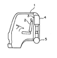
簡易ベッドが付設されていない右ハンドル車のキャブにおいて、運転者が簡便に休息をとることができるように、運転席のシートバックを後方へ大きくリクライニングさせるため、従来は、図5及び図6に示されているように、キャブ1の左側後隅部、すなわち、助手席2の後方隅部にキャブ1の内部空間を狭める傾斜面3が形成されて、その位置にスタック式エア吸入ダクト4が配置され、エア吸入ダクト4の下端が下方のエアクリーナ5と接続するように構成されているが、この場合には、傾斜面3がキャブ1内へ張り出しているために、運転席と同様なシートバックのリクライニング角を助手席2に許容させることができない不具合があった。なお、6は車両の搭載エンジンである。
【0003】
また、簡易ベッドが付設されていない左ハンドル車のキャブにおいても、運転席のシートバックを後方へ大きくリクライニングさせるためには、助手席が存在するキャブの右側後隅部に上記と同様な傾斜面を形成させて、その位置にスタック式エア吸入ダクトを配置する必要があり、従って、上記の場合と同様に助手席におけるシートバックのリクライニング角を大きくとることができないと共に、キャブの後部構造を右ハンドル車の場合と対称的に変更しなければならないので、左右ハンドル車に対するキャブの共用化が不可能となって、キャブのコストアップを招いていた。
【0004】
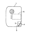
他方、スタック式エア吸入ダクト4及びエアクリーナ5がキャブ1の例えば左方に配置されていると、図7(A)に示されているように、車両に搭載された通常エンジン6の吸気マニホールド7とエアクリーナ5との連結は吸気管8により比較的簡単であるが、図7(B)に示されているように、車両の搭載エンジンがターボエンジン9の場合には、エアクリーナ5と過給タービン10とを連結する比較的長い吸気管11、及び、過給タービン10と吸気マニホールド7とを連結する吸気管12を必要とし、また、図7(C)に示されているように、車両の搭載エンジンがインタクーラターボエンジン13の場合にも、エアクリーナ5と過給タービン10とを連結する比較的長い吸気管11、及び、過給タービン10からインタクーラ14を経て吸気マニホールド7に至る吸気管15を必要としていた。
【0005】
従って、車両がターボエンジン9またはインタクーラターボエンジン13を搭載している場合には、比較的長い吸気管11を必要とするためコスト高となると同時に、キャブ1の下方における非常に狭い空間内に長い吸気管11を配置することは、実際上かなりの困難を伴う不具合があった。
【0006】
【発明が解決しようとする課題】
本発明の目的は、車両の搭載エンジンに対しスタック式エア吸入ダクトが付設されたキャブにおいて、左右ハンドル車に共用でき、かつ、運転席及び助手席のシートバックを後方へ大きくリクライニングさせることができるようにすることにある。
【0007】
【課題を解決するための手段】
このため、本発明にかかるキャブは、シートバックを後方へリクライニング可能な運転席及び助手席が設けられ、上記運転席及び上記助手席間の後壁部左右中央に上下に延びる車両前方への凹所が形成されて、搭載エンジン吸気用のスタック式エア吸入ダクトの立ち上がり部が上記凹所内に配置されると共に、上記立ち上がり部の上端から車幅方向に延びた上記エア吸入ダクトの端部に外気吸入口が設けられている。
【0008】
すなわち、運転席及び助手席間の後壁部左右中央に形成された上下に延びる車両前方への凹所内に搭載エンジン吸気用のスタック式エア吸入ダクトの立ち上がり部が配置されていると共に、上記立ち上がり部の上端から車幅方向に延びたエア吸入ダクトの端部に外気吸入口が設けられているので、キャブにおける左右の後隅部にはスタック式エア吸入ダクトを配置するためにキャブの内部空間を狭める従来のような傾斜面が全く不要となって、運転席及び助手席の後方に比較的大きなスペースを確保することができ、従って、運転席及び助手席の双方におけるシートバックをそれぞれ後方へ大きくリクライニングさせることが可能となり、運転者及び助手の双方が簡便に休息をとることができるようになると共に、キャブの後壁部を左右ハンドル車に共通して使用することができるため、キャブのコストを容易に低減させることが可能となる。
【0009】
【発明の実施の形態】
以下、本発明の実施形態例について説明する。
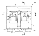
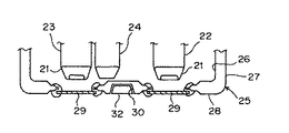
図1〜図3において、簡易ベッドが付設されていない右ハンドル車のキャブ20は、それぞれシートバック21を車両後方へリクライニング可能な運転席22及び助手席23と、中央席24とが内部に設置され、また、後壁部25がインナパネル26及びアウタパネル27からなるリヤパネル28により構成されていると共に、運転席22及び助手席23の各後方で後壁部25がそれぞれ車両後方へ突出して、それぞれにガラス窓29が形成されている。
【0010】
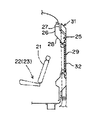
さらに、運転席22及び助手席23間の後方である後壁部25の中央部分には、上下に延びる車両前方への凹所30が形成されており、この凹所30内にスタック式エア吸入ダクト31の立ち上がり部32が配置され、立ち上がり部32の上端が車幅方向の左右に分岐して、それぞれの先端から図1における矢印のように外気を吸入できるように形成され、立ち上がり部32の下端が後記のように左右いずれかの吸気管33を介して、それぞれ搭載エンジン34に対する左右いずれかのエアクリーナ35に連結されている。
なお、スタック式エア吸入ダクト31の頂面は、キャブ20のチルト時に図示しない荷台の架装部分等に当たることのないように、後下方へ傾斜した形状となっている。
【0011】
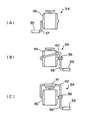
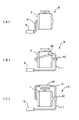
一方、図4(A)に示されているようにエンジン34が通常のエンジンである場合には、エアクリーナ35はエンジン34の吸気マニホールド36側である車両の左方に配置されて、エアクリーナ35と吸気マニホールド36とが吸気管37により連結される。
【0012】
しかしながら、図4(B)に示されているようにエンジン34がターボエンジンである場合には、エアクリーナ35はエンジン34の過給タービン38側である車両の右方に配置されて、エアクリーナ35と過給タービン38とが比較的短い吸気管39により連結され、過給タービン38と吸気マニホールド36とが吸気管40により連結される。
【0013】
また、図4(C)に示されているようにエンジン34がインタクーラターボエンジンである場合にも、エアクリーナ35はエンジン34の過給タービン38側である車両の右方に配置されて、エアクリーナ35と過給タービン38とが比較的短い吸気管39により連結され、過給タービン38と吸気マニホールド36とがインタクーラ41を通る吸気管42により連結される。
【0014】
上記キャブ20においては、スタック式エア吸入ダクト31の立ち上がり部32を配置するための凹所30が、後壁部25の中央部分に形成されていて、従来のようにキャブ20の左側後隅部等に傾斜面が形成されることはなく、また、後壁部25が運転席22及び助手席23の各後方でそれぞれ車両後方へ突出し、すなわち、キャブ20内部からみれば車両後方へスペースが広げられていると共に、ガラス窓29が形成されているために、後壁部25とガラス窓29との厚みの差だけ運転席22及び助手席23の各後方におけるキャブ20内部のスペースが車両後方へ一層大きく広げられている。
【0015】
従って、運転席22及び助手席23のシートバック21をそれぞれ随意に車両後方へリクライニングさせることができ、しかも、運転席22及び助手席23に対する後方スペースの拡大により、シートバック21のリクライニング角を容易に増大させることができるので、シートバック21のリクライニング角を自由に設定することによって、簡易ベッドが付設されていなくても運転者及び助手の双方が必要に応じて簡便に休息をとることが可能となる長所がある。
【0016】
また、スタック式エア吸入ダクト31の立ち上がり部32を配置するための凹所30が後壁部25の中央部分に形成されていて、後壁部25が左右対称的な構造を有しているので、このキャブ20を左ハンドル車のキャブとして使用しても上記の場合と全く同等の作用効果がえられ、このため、キャブ20は左右ハンドル車に共通して使用することができて、キャブ20の製造コストを容易に低減させることができる。
【0017】
さらに、スタック式エア吸入ダクト31の立ち上がり部32が後壁部25の中央部分に形成された凹所30内に配置されているため、搭載エンジン34の種類に応じてエアクリーナ35をエンジン34の左右いずれかに設置し、立ち上がり部32の下端に接続された吸気管33の向きを左右いずれかへ変えてエアクリーナ35に連結すると共に、エアクリーナ35をエンジン34側と連結するように構成すれば、エンジン34がターボエンジンまたはインタクーラターボエンジンである場合に、エアクリーナ35と過給タービン38とを連結する吸気管39を比較的短くすることができて、吸気管39等の配置が非常に楽となる等の特別な効果がある。
【0018】
【発明の効果】
本発明にかかるキャブにおいては、運転席及び助手席間の後壁部左右中央に形成された上下に延びる車両前方への凹所内に搭載エンジン吸気用のスタック式エア吸入ダクトの立ち上がり部が配置されていると共に、上記立ち上がり部の上端から車幅方向に延びたエア吸入ダクトの端部に外気吸入口が設けられていて、運転席及び助手席の双方におけるシートバックをそれぞれ後方へ大きくリクライニングさせることが可能となり、運転者及び助手の双方が簡便に休息をとることができるようになると共に、後壁部を左右ハンドル車に共通して使用することができるため、キャブのコストを容易に低減させることができるという実用上とくに大きな利点がある。
【図面の簡単な説明】
【図1】本発明の実施形態例における概略後面図。
【図2】図1のII−II矢視縦断面図。
【図3】図1の III−III 矢視横断面図。
【図4】上記実施形態例の要部上面図。
【図5】従来装置の概略側面図。
【図6】上記従来装置の要部上面図。
【図7】上記従来装置の要部上面図。
【符号の説明】
20 キャブ
22 運転席
23 助手席
25 後壁部
29 ガラス窓
30 凹所
31 スタック式エア吸入ダクト
32 立ち上がり部
33 吸気管
34 エンジン
35 吸気エアクリーナ
36 吸気マニホールド
37 吸気管
38 過給タービン
39、40 吸気管
41 インタクーラ
42 吸気管[0001]
BACKGROUND OF THE INVENTION
The present invention relates to a cab of a vehicle, and more particularly to a configuration of a cab provided with a stack type air intake duct for an installed engine.
[0002]
[Prior art]
In a cab of a right-hand drive vehicle that is not provided with a simple bed, in order to recline the seat back of the driver's seat greatly rearward so that the driver can easily take a rest, conventionally, FIG. 5 and FIG. As shown, an
[0003]
Also, even in a cab of a left-hand drive vehicle that does not have a cot, in order to recline the seat back of the driver's seat greatly backward, an inclined surface similar to the above is formed at the right rear corner of the cab where the passenger seat exists Therefore, it is necessary to place a stack type air intake duct at that position, so that the reclining angle of the seat back in the passenger seat cannot be increased as in the above case, and the rear structure of the cab is Since it has to be changed symmetrically with the case of a steering wheel vehicle, it becomes impossible to share the cab with respect to the left and right steering wheel vehicles, leading to an increase in the cost of the cab.
[0004]
On the other hand, when the stack type air intake duct 4 and the
[0005]
Therefore, when the vehicle is equipped with the
[0006]
[Problems to be solved by the invention]
An object of the present invention is that a cab in which a stack-type air suction duct is attached to a vehicle-mounted engine can be used for both left and right-hand drive vehicles, and the seat backs of a driver seat and a passenger seat can be greatly reclined rearward. There is in doing so.
[0007]
[Means for Solving the Problems]
For this reason, the cab according to the present invention is provided with a driver seat and a passenger seat that can recline the seat back to the rear, and a recessed portion forward of the vehicle that extends vertically in the left and right center of the rear wall between the driver seat and the passenger seat. And a rising portion of the stack type air intake duct for intake of the mounted engine is disposed in the recess, and outside air is extended to the end of the air intake duct extending in the vehicle width direction from the upper end of the rising portion. the suction port is provided, et al.
[0008]
That is, the rising of the stack type air intake duct for mounting the engine intake in the driver's seat and the recess in the vehicle front which extends vertically in the wall portion horizontal center after between the passenger seat is arranged, the Since the outside air intake port is provided at the end of the air intake duct that extends in the vehicle width direction from the upper end of the rising portion, the inside of the cab is arranged to arrange the stack type air intake duct at the left and right rear corners of the cab. The conventional inclined surface that narrows the space is completely unnecessary, and a relatively large space can be secured behind the driver's seat and the passenger seat. And the driver and assistant can take a rest easily and the rear wall of the cab It is possible to commonly use the Le vehicles, it is possible to easily reduce the cost of the cab.
[0009]
DETAILED DESCRIPTION OF THE INVENTION
Hereinafter, embodiments of the present invention will be described.
1 to 3, a
[0010]
Further, a
Note that the top surface of the stack type
[0011]
On the other hand, when the
[0012]
However, when the
[0013]
Also, as shown in FIG. 4C, even when the
[0014]
In the
[0015]
Accordingly, the
[0016]
Further, the
[0017]
Further, since the rising
[0018]
【The invention's effect】
In the cab according to the present invention, the driver's seat and the rising portion is located in the stack type air intake duct for mounting the engine intake in a recess in the front of the vehicle which extends vertically in the wall portion horizontal center after between passenger seat In addition, an air intake port is provided at the end of the air intake duct extending in the vehicle width direction from the upper end of the rising portion, and the seat backs in both the driver seat and the passenger seat are largely reclined rearward. This makes it possible for both the driver and the assistant to take a rest easily, and the rear wall can be used in common with the left and right steering wheel, thus reducing the cost of the cab easily. In particular, there is a great advantage in practical use.
[Brief description of the drawings]
FIG. 1 is a schematic rear view of an embodiment of the present invention.
2 is a longitudinal sectional view taken along the line II-II in FIG.
3 is a cross-sectional view taken along the line III-III in FIG.
FIG. 4 is a top view of the main part of the embodiment.
FIG. 5 is a schematic side view of a conventional apparatus.
FIG. 6 is a top view of the main part of the conventional device.
FIG. 7 is a top view of essential parts of the conventional device.
[Explanation of symbols]
20
Claims (2)
Priority Applications (1)
| Application Number | Priority Date | Filing Date | Title |
|---|---|---|---|
| JP17306697A JP3817841B2 (en) | 1997-06-13 | 1997-06-13 | Cab |
Applications Claiming Priority (1)
| Application Number | Priority Date | Filing Date | Title |
|---|---|---|---|
| JP17306697A JP3817841B2 (en) | 1997-06-13 | 1997-06-13 | Cab |
Publications (2)
| Publication Number | Publication Date |
|---|---|
| JPH115571A JPH115571A (en) | 1999-01-12 |
| JP3817841B2 true JP3817841B2 (en) | 2006-09-06 |
Family
ID=15953586
Family Applications (1)
| Application Number | Title | Priority Date | Filing Date |
|---|---|---|---|
| JP17306697A Expired - Lifetime JP3817841B2 (en) | 1997-06-13 | 1997-06-13 | Cab |
Country Status (1)
| Country | Link |
|---|---|
| JP (1) | JP3817841B2 (en) |
-
1997
- 1997-06-13 JP JP17306697A patent/JP3817841B2/en not_active Expired - Lifetime
Also Published As
| Publication number | Publication date |
|---|---|
| JPH115571A (en) | 1999-01-12 |
Similar Documents
| Publication | Publication Date | Title |
|---|---|---|
| US7874605B2 (en) | Utility vehicle | |
| US8037959B2 (en) | All terrain vehicle with radiator protection | |
| CN100420595C (en) | Cooling structure of electrical equipment in a vehicle | |
| JP4270974B2 (en) | Fuel tank arrangement structure in a vehicle | |
| CA2673393C (en) | Frame structure for vehicle | |
| US7735903B2 (en) | Utility vehicle | |
| JP2000280964A (en) | Body frame structure of motorcycle | |
| JP2007062615A (en) | Vehicle intake structure | |
| JP4678473B2 (en) | Vehicle fuel tank arrangement structure | |
| CN212765546U (en) | A suspension structure and a passenger car | |
| JP3817841B2 (en) | Cab | |
| JP3503404B2 (en) | Car floor structure | |
| JP2001180304A (en) | Vehicle fuel tank structure | |
| JP2009067072A (en) | Work vehicle | |
| JPS6045428A (en) | Arrangement structure of engine for motorcycle | |
| CN207889597U (en) | Car seat back frame safety belt hanging structure | |
| JP2000255278A (en) | Vehicle fuel tank structure | |
| JPH0680032A (en) | Rear-wheel drive vehicle | |
| JP2003072639A (en) | Motorcycle intake system parts mounting structure | |
| CN218892418U (en) | Door assembly and vehicle having same | |
| JPS63158485U (en) | ||
| JPH0121916Y2 (en) | ||
| JPH0813670B2 (en) | Rear body structure of the vehicle | |
| JPH06171382A (en) | Rear wheel driving vehicle | |
| JP4314914B2 (en) | Arrangement structure of auxiliary equipment for vehicle |
Legal Events
| Date | Code | Title | Description |
|---|---|---|---|
| A131 | Notification of reasons for refusal |
Free format text: JAPANESE INTERMEDIATE CODE: A131 Effective date: 20060214 |
|
| A521 | Written amendment |
Free format text: JAPANESE INTERMEDIATE CODE: A523 Effective date: 20060412 |
|
| TRDD | Decision of grant or rejection written | ||
| A01 | Written decision to grant a patent or to grant a registration (utility model) |
Free format text: JAPANESE INTERMEDIATE CODE: A01 Effective date: 20060523 |
|
| A61 | First payment of annual fees (during grant procedure) |
Free format text: JAPANESE INTERMEDIATE CODE: A61 Effective date: 20060605 |
|
| R150 | Certificate of patent or registration of utility model |
Free format text: JAPANESE INTERMEDIATE CODE: R150 |
|
| S531 | Written request for registration of change of domicile |
Free format text: JAPANESE INTERMEDIATE CODE: R313531 |
|
| R371 | Transfer withdrawn |
Free format text: JAPANESE INTERMEDIATE CODE: R371 |
|
| S531 | Written request for registration of change of domicile |
Free format text: JAPANESE INTERMEDIATE CODE: R313531 |
|
| R350 | Written notification of registration of transfer |
Free format text: JAPANESE INTERMEDIATE CODE: R350 |
|
| FPAY | Renewal fee payment (event date is renewal date of database) |
Free format text: PAYMENT UNTIL: 20100623 Year of fee payment: 4 |