JP3816162B2 - Beamwidth control method for adaptive antenna - Google Patents
Beamwidth control method for adaptive antenna Download PDFInfo
- Publication number
- JP3816162B2 JP3816162B2 JP27624996A JP27624996A JP3816162B2 JP 3816162 B2 JP3816162 B2 JP 3816162B2 JP 27624996 A JP27624996 A JP 27624996A JP 27624996 A JP27624996 A JP 27624996A JP 3816162 B2 JP3816162 B2 JP 3816162B2
- Authority
- JP
- Japan
- Prior art keywords
- antenna
- beam width
- traffic
- sector
- beams
- Prior art date
- Legal status (The legal status is an assumption and is not a legal conclusion. Google has not performed a legal analysis and makes no representation as to the accuracy of the status listed.)
- Expired - Fee Related
Links
Images


Classifications
-
- H—ELECTRICITY
- H01—ELECTRIC ELEMENTS
- H01Q—ANTENNAS, i.e. RADIO AERIALS
- H01Q3/00—Arrangements for changing or varying the orientation or the shape of the directional pattern of the waves radiated from an antenna or antenna system
- H01Q3/26—Arrangements for changing or varying the orientation or the shape of the directional pattern of the waves radiated from an antenna or antenna system varying the relative phase or relative amplitude of energisation between two or more active radiating elements; varying the distribution of energy across a radiating aperture
- H01Q3/2605—Array of radiating elements provided with a feedback control over the element weights, e.g. adaptive arrays
-
- H—ELECTRICITY
- H01—ELECTRIC ELEMENTS
- H01Q—ANTENNAS, i.e. RADIO AERIALS
- H01Q25/00—Antennas or antenna systems providing at least two radiating patterns
Description
【0001】
【発明の属する技術分野】
この発明は、移動通信や構内無線などに利用される基地局用アンテナに用いられるアダプティブアンテナに関する。
【0002】
【従来の技術】
移動通信用の基地局アンテナとして、セクタビームを形成するアンテナが用いられている。このアンテナは基地局から見て水平面内の全角度領域をある角度領域に分割して複数のビームによりカバーするものである。例えばビーム幅60度のビームを円周方向に6個配置した例などがあげられる。このセクタビームを形成する手段としては、所定のビーム幅の素子パターンをもつアンテナ素子を各セクタ毎に1個用いることが一般的である。その一例として、図10に示すような反射板付きダイポールアンテナがあげられる。このアンテナの場合、反射板の大きさや反射板からのダイポールの高さを適当に設定することによりビーム幅の変更が可能である。
【0003】
以上のようなセクタビームを基地局で形成することにより、アンテナ利得を上げて送受信特性を向上させたり、ビーム間で周波数の共用を行い電波資源の有効活用を行うことが可能になる。
【0004】
【発明が解決しようとする課題】
しかしながら、従来方式によるセクタビームのビーム幅は固定されるものであるため、基地局のカバーするサービスエリア内での通信量のビーム間での不均一性に対する柔軟性は無いと言える。例えば、特定のセクタビームのエリア内では通信する端末が混雑しているのに、他のセクタビームのエリア内では通信容量に対して空いている状態になっているような場合が起こり得る。
【0005】
このような場合、基地局を効率的に利用しているとは言えない。このような通信量のアンバランスが定常的に起こるものであれば、最初からセクタビームのビーム幅を変えたり、各セクタで収容できるチャネル数を変えて設定することにより対処は可能であるが、時間的にセクタ間での通信状況が変化していくような場合には対処は不可能である。
【0006】
本発明は、このような問題点を解決するためになされたものであり、セクタビームのビーム幅を各セクタの収容する通信量(通信端末数)を均一化するように、各セクタビームのビーム幅とビーム方向を適応制御するアダプティブアンテナを提案することを目的とする。
【0007】
【発明を解決するための手段】
本発明では、上記課題を解決するために、所定の放射パターンを形成するための複数の放射素子と、全体として所定のサービスエリアをカバーするため各放射素子の励振重みづけを設定する設定部からなるアダプティブアンテナにおいて、アンテナを介して送信されるべき情報量を検出する手段を更に具備し、この情報量の大きさに応じて前記放射素子の励振重み付けを修正することを特徴とする。
【0008】
具体的には、本発明は複数のビームを形成するアンテナであり、前記ビームで通信する通信量情報をビーム毎に認識する手段を有し、前記通信量情報を元に前記ビームのパターンを制御する手段を有する。
【0009】
このような構成にすることにより、ビーム毎の通信量の情報を元に、この通信量を均一化するように各セクタビームのパターンを制御することができ、通信端末の分布状況に柔軟に対応でき、基地局のもつ通信容量を効果的に利用できる効果がある。
【0010】
例えば、ある時刻において一つのビームがカバーするエリアに多くの移動局が集中した場合を想定すると、そのビームを形成するアンテナを介して伝送される情報量が急激に増大するため、収容できる移動局数を超えるとそのエリアに存在する移動局は新たに通信を開始することができなくなる。この場合にそのアンテナでカバーしていたエリアを小さくするようにビームのパターンを修正すると共に、カバーからはずれたエリアを別のアンテナでカバーするようにビームのパターンを修正する。このようにビ−ムのパタ−ンを修正すると、カバーするエリアが狭くなる場合には、そこに含まれる移動局数を減少させることができるため、そのアンテナを介して伝送される情報量の増大を抑制することが可能となる。また新たに別のアンテナでカバーされたエリアに含まれる移動局はその別のアンテナを介して通信を行うことができるため、一つのアンテナを介して伝送される情報量の偏りをなくし、トラヒックの集中を軽減することが可能となる。
【0011】
また、本発明は、複数のビームを形成するアンテナであり、前記ビームは各々複数のアンテナ素子により合成されて形成され、前記アンテナ素子に所定の励振ウェイトを設定するためのウェイト設定部を有し、前記ウェイト設定部はアンテナ制御部により制御され、前記アンテナ制御部への入力は各ビーム毎の通信量情報であり、前記ビーム毎の通信量情報を認識する手段を有する。
【0012】
このような構成により、アンテナ制御機からの制御によりビーム毎に独立の励振ウェイトを設定し、ビーム毎の通信情報量から各セクタの通信量を均一化するように各セクタビームのパターンを制御することができる。
【0013】
また、前記アダプティブアンテナを送信用アンテナと受信用アンテナに別個に設け、前記送信用アンテナと受信用アンテナは相似形であり、その大きさの比は送信周波数と受信周波数の比の逆数に一致していることを特徴とする。
このような構成により、送信アンテナと受信アンテナに同一励振ウェイトを設定することにより、同一形状のパターンをつくることができる。
【0014】
また、本発明では、アンテナ設置場所から水平面内の全角度領域を複数のビームでカバーする基地局アンテナであり、前記ビームで通信する通信量情報をビーム毎に認識する手段を有し、前記通信量情報を元に前記ビームのパターンを制御するアンテナ制御部を有し、前記アンテナ制御部において、最も通信量の大きなビームのビーム幅を狭くし、最も通信量の少ないビーム幅を広くするように制御することを特徴とする。
【0015】
このような構成により、ビーム毎で通信する通信量情報を認識し、これを均一化するように、最も通信量の大きなビームのビーム幅を狭くし、最も通信量の少ないビーム幅を広くすることができ、通信端末の分布のアンバランスに柔軟に対応でき、基地局のもつ通信容量を効果的に利用できる効果がある。
【0016】
また、前記アンテナ制御部において、最も通信量の大きなビームのビーム幅の減少量と、最も通信量の少ないビーム幅の増加量を一致するように制御することにより、全ビームのビーム幅の合計が一定値となるようにすることができる。
【0017】
また、前記アンテナ制御部において、最も通信量の大きなビームと最も通信量の少ないビーム以外のビームについて、ビーム幅を維持した状態でビーム方向を変化させるように制御することにより、ビーム幅の変化に伴うサービスエリアの変化に対応して各ビームの方向を調整することができる。
【0018】
また、前記アンテナ制御部において、最も通信量の大きなビームの通信量が予め設定したある通信量を超えたときにビームパターンの制御を行うことにより、特定のビームについて通信量が混雑した状況において初めて制御を開始するようにできる。
【0019】
また、前記アンテナ制御部において、所定のパターン形状を実現するために設定する励振ウェイト量を記憶装置に予め複数記憶しておき、前記記憶装置の中から最適な励振ウェイト量を選択して各アンテナ素子へ設定することにより、記憶している励振ウェイト群の中から最適なパターンを形成する励振ウェイトを選んで設定することができる。
【0020】
また、前記アンテナ制御部において、所望のパターン形状との誤差が最小になるような励振ウェイト量を計算により求め、各アンテナ素子へ設定することにより、所望のパターンに最も近い最適なパターン形成を自由に行うことができる。
【0021】
また、前記アンテナ制御部において、所望のパターン形状との誤差が最小になるような励進ウェイト量を逐次的に計算して求め、各アンテナ素子へ逐次的に更新し設定することにより、初期パターンから所望のパターンに最も近い最適なパターンへ徐々に変化させていくことができる。
さらに本発明は、アンテナ設置場所から水平面内の全角度領域を複数のビームでカバーするアダプティブアンテナにおけるビーム幅制御方法であって、前記ビームで通信する通信量情報をビーム毎に認識し、最も通信量の大きなビームと最も通信量の小さなビームを把握し、前記最も通信量の大きなビームのビーム幅の減少量と最も通信量の少ないビーム幅の増加量を一致させ、かつ他のビームについてはビーム幅を固定したままビーム方向のみ制御することを特徴とする。
このような構成により、全ビームのビーム幅の合計が一定値となるようにすることができる。
また本発明は、アンテナ設置場所から水平面内の全角度領域を複数のビームでカバーするアダプティブアンテナにおけるビーム幅制御方法であって、各ビームのビーム幅は、所定の段階に離散的または選択的な設定が可能であり、前記ビームで通信する通信量情報をビーム毎に認識し、最も通信量の大きなビームと最も通信量の小さなビームを把握し、前記最も通信量の大きなビームのビーム幅を一段階狭くし、最も通信量の少ないビーム幅を一段階広くし、かつ他のビームについてはビーム幅を固定したままビーム方向のみ制御する第 1 の制御を行い、各ビーム間の通信量の差が予め定められた許容値以下になるまで前記第1の制御を繰り返し実行することを特徴とする。
さらに本発明は、アンテナ設置場所から水平面内の全角度領域を複数のビームでカバーするアダプティブアンテナにおけるビーム幅制御方法であって、各ビームのビーム幅は、所定の段階に離散的または選択的な設定が可能であり、前記ビームで通信する通信量情報をビーム毎に認識し、最も通信量の大きなビームと最も通信量の小さなビームを把握し、前記最も通信量の大きなビームのビーム幅を一段階狭くし、最も通信量の少ないビーム幅を一段階広くし、かつ他のビームについてはビーム幅を固定したままビーム方向のみ制御する第 1 の制御を行い、前 記最も通信量の大きいビームのビーム幅を、最も狭くできる限界になるまで前記第1の制御を繰り返すことを特徴とする。
【0022】
【発明の実施の形態】
以下、図面を参照して本発明の実施形態を説明する。
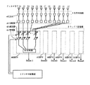
図1に本発明の実施形態に係るアダプティブアンテナの構成例である。いま、一例として、6セクタビームにより水平面内の全角度領域をカバーする基地局用アンテナとしての応用例について説明する。
【0023】
図1に示すように、受信アンテナ1と送信アンテナ2の二つで構成され、どちらも12素子アレイにより6個のセクタビームを形成する。この二つの12素子アレイアンテナの大きさは、送信、受信に用いられる電波の周波数帯(または波長の大きさ)に応じてアンテナの大きさ、素子間隔等が決定されるものとする。具体的には送信アンテナ、受信アンテナは大きさが異なる相似形状として構成され、送信アンテナの形状パラメータは受信アンテナの形状の(受信周波数/送信周波数)倍とする。例えば送信周波数が1GHz、受信周波数が2GHzの場合には、送信アンテナの大きさは受信アンテナの大きさの2倍となる。このように設定することにより、アンテナの大きさは使用する電波の波長の大きさにより規格化され、波長の大きさに関わらず、波長に対するアンテナの大きさ、素子間隔の比率は同一となる。また受信アンテナの受信パターンと送信アンテナの送信パターンは同一の励振ウェイトを設定することにより同一のパターンになるように設計することができる。
【0024】
受信アンテナ1を構成する各アンテナ素子からの受信信号は受信増幅部3と直接接続し、この後にウェイト設定部5において各受信信号に重み付けを行い合成した後に受信部8に入力する。また、送信部9からの送信信号は、分配後、ウェイト設定部6において各送信信号に重み付けされた後、送信増幅部4で増幅され、アンテナ素子へ伝達される。ここで、受信部8では受信されたRF信号をベースバンド信号に変換し、送信部9では変調されたベースバンド信号をRF信号に変換する。受信部8および送信部9は信号処理部10に接続され、信号処理部10ではベースバンドでの信号の変復調などを行う。制御部11は信号処理部10と外部の信号伝達の制御や無線回線管理等を行う他に、各セクタ毎の通信量情報を認識する。この通信量情報は、各セクタ毎にその瞬時に通信している端末数やチャネルの稼動数などである。この制御部11から通信量情報を抽出し、アンテナ制御部7へ入力する。アンテナ制御部7は計算処理および記憶できる機能を有し、入力した通信量情報をもとにアンテナ素子へ設定する励振ウェイトを決定し、ウェイト設定部5、6へ送出する。この励振ウェイト分布は、受信アンテナと送信アンテナに設けられたウェイト設定部において同一とする。
【0025】
図2には、ウェイト設定部および増幅部の構成について受信アンテナを例にとり説明する。ここで12個のアンテナ素子21、22、23、24、25、26、27、28、29、30、31、32により6個のセクタビームを形成する。各アンテナ素子には、低雑音増幅器(LNA)41と分配器42が各々接続される。例えば、この分配器42を4分配とすると、これは一つのアンテナ素子が4つのセクタビーム形成に共用されることを示す。受信増幅部3はこの低雑音増幅器と分配器により構成される。ウェイト設定部5には各セクタ毎のビーム形成回路(BFN)46、47、48、49、50、51が設けられ、各BFNは7個(もしくは8個)のアンテナ素子に励振ウェイトを設定し、ウェイト付けられた受信信号を合成器45によりセクタ毎に合成し、受信部へ伝達する。励振ウェイトのうち、振幅ウェイトの設定は可変減衰器43により、位相ウェイトの設定は可変移相器44に行う。この制御はアンテナ制御部7が行う。
【0026】
以上、受信アンテナの例であるが、送信アンテナについても同様な構成であり、送信では低雑音増幅器が高出力増幅器(HPA)になり、分配器と合成器が入れ替わる。
【0027】
図3にアンテナにアンテナ上面図を示す。正12角形上に12個のアンテナ素子を配列する。また、図4にアンテナ素子21の概観を示す。エレベーション面にビーム方向を偏位させ、例えば水平方向から下向きにビーム形状を成形させるために、複数の単位アンテナを鉛直方向に配置して構成する。ここで、もちろん、エレベーション方向でのビーム成形の必要が無い場合には単一のアンテナでも構わない。この単位アンテナとしては、誘電体基板61上に形成された平面アンテナ60を用いる。アンテナ方式については、この他、他の方式のマイクロストリップアンテナ、反射板付きダイポールなどを利用することが可能である。また、この場合の給電方法としてマイクロストリップ線路によるシリーズ給電もしくはトーナメント給電方法を用いることができる。
【0028】
本発明の基本的な構成要素は、複数のビームを形成するアンテナにおいて、各ビーム毎の通信量情報を認識する手段としての制御部を有することと、この情報を元にビームパターンを制御する手段としてのアンテナ制御部を有することである。このような構成により、各セクタでの通信量の均一化をはかり、基地局全体を効率的に運用することを目的として、各セクタ毎の通信量情報を元に、これらを均一化するように各セクタビームの方向およびビーム幅を変化させることができる。従って、ビーム間での通信量の変動やアンバランスに対して柔軟に対応でき、基地局のもつ通信容量を有効に活用できる効果がある。言葉を変えれば、収容できる端末数を増やすことができるので、等価的に低コスト化がはかられる。
【0029】
また、上記の基本的構成要素に加え、各ビームのビーム形状を変更するための手段として、各ビームの形成に関与するアンテナ素子が複数個あり、これらに励振ウェイトを設定するためのウェイト設定部を設け、これをアンテナ制御部により制御する。このような構成により、簡単な構成および簡単な制御によりビーム毎に独立にビーム成形を行うことができる。
【0030】
また、送受のアンテナを相似形状として、その形状の比を送受の周波数比の逆数とすることにより、送受信で設定する励振ウェイトを同一とした場合に同一のビーム形状が実現できる。このような構成により、基地局が形成するセクタビームが常に送受で一致し、送受パターンが異なることに起因する通信障害を避けることができ、常に良好な通信環境を維持することができる。
【0031】
図5には、アンテナ制御部7における制御の流れの一例を示す。
基本的な動作として、ビーム毎での通信量情報を入力し、この通信量がビーム間でバラツキがある場合に均一化するように、各ビームの方向・ビーム幅を変化させ、そのようなビームを形成するための励振ウェイトを求めてウェイト制御信号としてウェイト設定部へ送出する。以下に、その処理の一例を示す。
【0032】
1.各セクタビームのビーム幅は離散的、選択的に設定可能なものとし、例えば30度、45度、60度、75度、90度の5段階に制御可能とする。初期値(ノミナル値)のビーム幅は60度とする。
【0033】
2.セクタ毎の通信量をある単位時間あたり平均をとり、最も混雑しているセクタと最も空いているセクタを把握する。
3.最も通信量の混雑しているセクタのビーム幅を1段階狭くし(例えば60度を45度ビームにする)、最も通信量の少ない空いているセクタのビーム幅を1段階広くする(例えば60度を75度にする)。他のビームについてはビーム幅を固定したまま、ビーム方向のみの調整を行う。このような条件で、各セクタビームの所望パターンを設定する。[処理1]
4.上記所望パターンに合致するようにアンテナ励振ウェイトを求める。この方法としては、記憶しているパターン例から最適なものを選び出す方法や最急降下法などにより所望パターンとの二乗誤差が最小になるように励振ウェイトを収束させていく方法などを用いることができる。[処理2]
5.上記の処理2において、求められた励振ウェイトを各セクタに設定する。こうすることにより、各セクタのビーム形状は初期値パターンから所望パターンへ変化する。
【0034】
6.セクタ間の通信トラフィック量の差がある許容値以下になるまで、もしくは通信が集中している特定のセクタがこれ以上ビーム幅を狭くできなくなるまで上記2.から5.の手順を再度繰り返す。この場合、通信状況に応じてビーム幅を変化させるビームを随時選んで行う。
【0035】
以上の制御によるビーム幅の可変例を以下に示す。
図6から図9に、ビーム幅可変セクタビームによる基地局パターン配置例を示す。図6には全て60度のセクタビームとなる初期状態でのパターンを示す。図7には特定の方向(+X方向)にユーザが集中している場合のパターン配置例を示す。このようなパターンは、基地局から見て人の集まるところ(駅、オフィス街、イベント会場など)が単一方向にある場合に有効である。図8には2方向(+X方向と−X方向)にユーザが集中する場合のパターン配置例を示す。例えば、基地局が通行量の多い幹線道路途中に配置されるような場合に有効である。図9にはユーザが集中する領域がX>0となるところにある場合でのパターン配置例を示す。例えば、基地局が海岸や山岳部の付近に配置され、地形的にユーザ数の分布が不均一な場合に有効である。
【0036】
以上のように、本発明のアダプティブアンテナは、基地局がカバーするエリアにおけるユーザ分布のアンバランスを補償することができる。セクタビームの可変は、地形や交通などの影響に起因する準固定的な通信トラフィックのアンバランスに対応するのみならず、特定の時間帯に起きる通信トラフィックのアンバランス(例えば、イベント会場などでイベント時に起きる通信混雑、オフィス街での時間帯による通信量の差など)に対する適応制御も可能である。また、通信が混雑しているセクタビームを鋭くすることは、そのカバーエリアでのアンテナ利得を上げることと等価になり、その利得上昇分だけ送信出力を節約することも可能になる利点もある。以上の理由から、本発明のアダプティブアンテナは基地局カバーするサービスエリアの中の通信トラフィック環境に非常に柔軟に対応するものであり、その利用効率は非常高いと言える。収容するユーザ数(端末数)を等価的に数倍にすることが可能であり、効果は絶大である。
【0037】
アンテナ制御部での制御において以下のような変更・追加等を行っても本発明の効果は同様である。
アンテナ制御部において、最も通信量の大きなビームのビーム幅の減少量と、最も通信量の少ないビーム幅の増加量を一致するように制御する。このような制御により、全ビームのビーム幅の合計が一定値となり、全てのセクタにビームによりカバーする角度領域が一定となるように各ビームのビーム方向の調整が行える。このため基地局でカバーすべき領域を常にカバーする上で有効である。
【0038】
また、アンテナ制御部において、最も通信量の大きなビームと最も通信量の少ないビーム以外のビームについて、ビーム幅を維持した状態でビーム方向を変化させるように制御することにより、ビーム幅の変化に伴うサービスエリアの変化に対応して各ビームの方向を調整することができる。このため基地局でカバーすべき領域を常にカバーする上で有効である。
【0039】
また、アンテナ制御部において、最も通信量の大きなビームの通信量が予め設定したある通信量を超えたときにビームパターンの制御を行うようにしてもよい。このような制御により、特定のビームについて通信量が混雑した状況において初めて制御を開始し、必要な場合にのみビームの変更を行うように制御することができる。アンテナ全体の制御を簡単化することができ、有効である。
【0040】
また、アンテナ制御部において、所定のパターン形状を実現するために設定する励振ウェイト量を記憶装置に予め複数記憶しておき、記憶装置の中から所定の励振ウェイト量を選択して各アンテナ素子へ設定する。このような制御により、記憶している励振ウェイト群の中から最適なパターンを形成する励振ウェイトを選んで設定することができる。励振ウェイトの選択、設定を短時間で行える利点がある。
【0041】
また、アンテナ制御部において、所望のパターン形状との誤差が最小になるような励振ウェイト量を計算により求め、各アンテナ素子へ設定する。このような制御により、所望のパターンに最も近い最適なパターン形成を自由に行うことができる。ここで所望パターンは任意に決めることができ、さまざまな通信環境(通信量のアンバランス)により柔軟に対応することができる。
【0042】
また、アンテナ制御部において、所望のパターン形状との誤差が最小になるような励振ウェイト量を逐次的に計算して求め、各アンテナ素子へ逐次的に更新し設定してもよい。このような制御により、ビーム形状は初期パターンから所望のパターンへ徐々に変化させていくことができる。この場合、ビーム切り替えにより、セクタが変更されたために、通信が遮断されるような状況を避けることができる利点がある。
【0043】
また一つのサービスエリアに含まれる移動局に対して発呼要求、着呼要求が大量に発生し、トラヒックが集中した場合には、そのサービスエリアをカバーする複数の同一形状のビームを重ねて配置するようアンテナ素子の励振ウェイトを設定することも可能である。このような構成によっても、特定のエリアに集中した情報量の伝送負荷を分散させることができる。
【0044】
以上、本発明の実施形態について説明したが、本発明の基本的な構成および制御方法を逸脱しない範囲で実施例の変更を行っても構わない。例えば、多角形柱状の形状を有するセクタアンテナにおいては、セクタ数やアンテナ素子数については任意に設定されるものであるし、励振ウェイトの設定手段などについても他の手段によっても構わない。一例として、ベースバンドにおけるディジタル信号の領域において、ディジタル信号処理回路の中でこのような励振ウェイト設定を行うような構成にしても構わない。
【0045】
【発明の効果】
以上説明したように、本発明のアダプティブアンテナでは、セクタビームの形状を通信環境に応じて柔軟に可変することができる。例えば、各セクタでの通信量の均一化をはかり、基地局全体を効率的に運用することを目的として、各セクタ毎の通信量情報を元に、これらを均一化するように各セクタビームの方向およびビーム幅を変化させることができる。従って、基地局のもつ通信容量を有効に活用できる効果がある。また、収容できる端末数を増やすことができ、等価的に低コスト化がはかることができる。
【図面の簡単な説明】
【図1】本発明の実施形態に係るアダプティブアンテナの構成を示す図。
【図2】本発明の実施形態に係るアダプティブアンテナの受信増幅部およびウェイト設定部の構成を示す図。
【図3】本発明の実施形態に係るアダプティブアンテナのアンテナ素子の上面図。
【図4】同実施形態に係るアダプティブアンテナのアンテナ素子の概観図。
【図5】同実施形態に係るアダプティブアンテナのアンテナ制御部における制御手順を示す図。
【図6】同実施形態に係るアダプティブアンテナによるセクタビーム形成例を示す図。
【図7】同実施形態に係るアダプティブアンテナによるセクタビーム形成例を示す図。
【図8】同実施形態に係るアダプティブアンテナによるセクタビーム形成例を示す図。
【図9】同実施形態に係るアダプティブアンテナによるセクタビーム形成例を示す図。
【図10】従来例におけるセクタビームを形成するアンテナ構成例を示す図。
【符号の説明】
1・・・ 受信アンテナ
2・・・ 送信アンテナ
3・・・ 受信増幅部
4・・・ 送信増幅部
5、6・・・ ウェイト設定部
7・・・ アンテナ制御部
8・・・ 受信部
9・・・ 送信部
10・・・ 信号処理部
11・・・ 制御部
21〜32・・・ アンテナ素子
41・・・ LNA
42・・・ 分配器
43・・・ 減衰器
44・・・ 移相器
45・・・ 合成器
46、47、48、49、50、51・・・ RFN
60・・・ 平面アンテナ
61・・・ 誘電体基板[0001]
BACKGROUND OF THE INVENTION
The present invention relates to an adaptive antenna used for a base station antenna used for mobile communication, local radio, and the like.
[0002]
[Prior art]
As a base station antenna for mobile communication, an antenna that forms a sector beam is used. This antenna divides the entire angle area in the horizontal plane as viewed from the base station into a certain angle area and covers it with a plurality of beams. For example, an example in which six beams having a beam width of 60 degrees are arranged in the circumferential direction can be given. As means for forming this sector beam, one antenna element having an element pattern having a predetermined beam width is generally used for each sector. As an example, there is a dipole antenna with a reflector as shown in FIG. In the case of this antenna, the beam width can be changed by appropriately setting the size of the reflecting plate and the height of the dipole from the reflecting plate.
[0003]
By forming the sector beam as described above at the base station, it is possible to improve the transmission / reception characteristics by increasing the antenna gain, or to effectively use radio wave resources by sharing the frequency between the beams.
[0004]
[Problems to be solved by the invention]
However, since the beam width of the sector beam according to the conventional method is fixed, it can be said that there is no flexibility with respect to non-uniformity between beams of traffic in the service area covered by the base station. For example, there may occur a case where terminals communicating with each other are congested in a specific sector beam area, but the communication capacity is empty in other sector beam areas.
[0005]
In such a case, it cannot be said that the base station is used efficiently. If this kind of traffic unbalance occurs regularly, it can be dealt with by changing the beam width of the sector beam from the beginning or changing the number of channels that can be accommodated in each sector, It is impossible to cope with the situation where the communication status between sectors changes over time.
[0006]
The present invention has been made to solve such a problem, and the beam of each sector beam is set so that the beam volume of the sector beam is uniformized in the amount of communication (number of communication terminals) accommodated in each sector. The purpose is to propose an adaptive antenna that adaptively controls width and beam direction.
[0007]
[Means for Solving the Invention]
In the present invention, in order to solve the above-described problem, a plurality of radiating elements for forming a predetermined radiating pattern and a setting unit for setting an excitation weight of each radiating element to cover a predetermined service area as a whole The adaptive antenna is further provided with means for detecting the amount of information to be transmitted via the antenna, and the excitation weight of the radiating element is modified according to the magnitude of the information amount.
[0008]
Specifically, the present invention is an antenna that forms a plurality of beams, and has means for recognizing the traffic information communicated by the beam for each beam, and controls the beam pattern based on the traffic information. Means to do.
[0009]
With this configuration, it is possible to control the pattern of each sector beam based on information on the amount of communication for each beam so that the amount of communication is uniform, and flexibly respond to the distribution status of communication terminals It is possible to effectively use the communication capacity of the base station.
[0010]
For example, assuming that a large number of mobile stations are concentrated in an area covered by one beam at a certain time, the amount of information transmitted via the antenna that forms the beam increases rapidly. If the number is exceeded, the mobile station existing in the area cannot newly start communication. In this case, the beam pattern is corrected so as to reduce the area covered by the antenna, and the beam pattern is corrected so as to cover an area outside the cover with another antenna. If the beam pattern is corrected in this way, the number of mobile stations included in the covered area can be reduced when the area to be covered becomes narrow. Therefore, the amount of information transmitted through the antenna can be reduced. The increase can be suppressed. In addition, since a mobile station included in an area newly covered by another antenna can perform communication via the other antenna, the bias of the amount of information transmitted through one antenna is eliminated, and traffic is reduced. It is possible to reduce concentration.
[0011]
Further, the present invention is an antenna for forming a plurality of beams, each of the beams is formed by combining a plurality of antenna elements, and has a weight setting unit for setting a predetermined excitation weight for the antenna elements. The weight setting unit is controlled by an antenna control unit, and the input to the antenna control unit is communication amount information for each beam, and has means for recognizing the communication amount information for each beam.
[0012]
With such a configuration, an independent excitation weight is set for each beam under the control of the antenna controller, and the pattern of each sector beam is controlled so as to equalize the communication amount of each sector from the communication information amount for each beam. be able to.
[0013]
In addition, the adaptive antenna is provided separately for the transmitting antenna and the receiving antenna, the transmitting antenna and the receiving antenna are similar, and the ratio of the sizes matches the reciprocal of the ratio of the transmission frequency and the reception frequency. It is characterized by.
With such a configuration, a pattern having the same shape can be created by setting the same excitation weight for the transmission antenna and the reception antenna.
[0014]
In the present invention, the antenna is a base station antenna that covers all angle regions in a horizontal plane from the antenna installation location with a plurality of beams, and has means for recognizing the communication amount information communicated by the beams for each beam. It has an antenna control unit that controls the beam pattern based on the amount information, and in the antenna control unit, the beam width of the beam with the largest communication amount is narrowed and the beam width with the least communication amount is widened. It is characterized by controlling.
[0015]
With this configuration, the beam width of the beam with the largest traffic volume is narrowed and the beam width with the least traffic volume is widened so that the traffic volume information communicated for each beam can be recognized and uniformized. It is possible to flexibly cope with the unbalance of the distribution of communication terminals, and to effectively use the communication capacity of the base station.
[0016]
In addition, the antenna control unit controls the beam width decrease amount of the beam with the largest communication amount to coincide with the beam width increase amount with the least communication amount, so that the sum of the beam widths of all the beams is obtained. It can be set to a constant value.
[0017]
Further, the antenna control unit controls the beam width to be changed by changing the beam direction while maintaining the beam width for the beam other than the beam having the largest communication amount and the beam having the least communication amount. The direction of each beam can be adjusted in accordance with the accompanying change in the service area.
[0018]
In addition, the antenna control unit performs the beam pattern control when the communication amount of the beam with the largest communication amount exceeds a predetermined communication amount, and for the first time in a situation where the communication amount of a specific beam is congested. Control can be started.
[0019]
In the antenna control unit, a plurality of excitation weight amounts set in order to realize a predetermined pattern shape are stored in advance in a storage device, and an optimum excitation weight amount is selected from the storage device and each antenna is selected. By setting the element, it is possible to select and set an excitation weight that forms an optimum pattern from the stored excitation weight group.
[0020]
In the antenna control unit, an excitation weight amount that minimizes an error from a desired pattern shape is obtained by calculation, and an optimum pattern formation closest to the desired pattern can be freely set by setting to each antenna element. Can be done.
[0021]
Further, the antenna control unit sequentially calculates and obtains an excitation weight amount that minimizes an error from a desired pattern shape, and sequentially updates and sets each antenna element to thereby obtain an initial pattern. Can be gradually changed to an optimum pattern closest to the desired pattern.
Furthermore, the present invention is a beam width control method in an adaptive antenna that covers a plurality of angle areas in a horizontal plane from an antenna installation location with a plurality of beams. The beam having the largest communication amount and the beam having the smallest communication amount are grasped, the decrease amount of the beam width of the beam having the largest communication amount is matched with the increase amount of the beam width having the least communication amount, and the other beam is a beam. Only the beam direction is controlled with the width fixed.
With this configuration, the total beam width of all the beams can be a constant value.
The present invention also relates to a beam width control method in an adaptive antenna that covers a plurality of beams from a place where an antenna is installed in a horizontal plane, and the beam width of each beam is discrete or selective at a predetermined stage. It can be set, recognizes the traffic information to be communicated by the beam for each beam, grasps the beam with the largest traffic and the beam with the smallest traffic, and sets the beam width of the beam with the largest traffic to one. Narrow the step, widen the beam width with the least amount of communication by one step, and control the beam direction for other beams with the beam width fixed. 1 And the first control is repeatedly executed until the difference in the traffic between the beams becomes equal to or less than a predetermined allowable value.
Furthermore, the present invention relates to a beam width control method in an adaptive antenna that covers a plurality of angle areas in a horizontal plane from an antenna installation location, wherein the beam width of each beam is discrete or selective at a predetermined stage. It can be set, recognizes the traffic information to be communicated by the beam for each beam, grasps the beam with the largest traffic and the beam with the smallest traffic, and sets the beam width of the beam with the largest traffic to one. Narrow the step, widen the beam width with the least amount of communication by one step, and control the beam direction for other beams with the beam width fixed. 1 Control, before The first control is repeated until the beam width of the beam having the largest communication amount reaches the limit where the beam can be narrowed to the smallest.
[0022]
DETAILED DESCRIPTION OF THE INVENTION
Hereinafter, embodiments of the present invention will be described with reference to the drawings.
FIG. 1 is a configuration example of an adaptive antenna according to an embodiment of the present invention. Now, as an example, an application example as an antenna for a base station that covers all angle areas in a horizontal plane with a 6-sector beam will be described.
[0023]
As shown in FIG. 1, the receiving
[0024]
Received signals from the respective antenna elements constituting the receiving
[0025]
In FIG. 2, the configuration of the weight setting unit and the amplification unit will be described using a reception antenna as an example. Here, six antenna beams are formed by the twelve
[0026]
The above is an example of the receiving antenna, but the transmitting antenna has the same configuration. In transmission, the low noise amplifier becomes a high output amplifier (HPA), and the distributor and the combiner are switched.
[0027]
FIG. 3 shows a top view of the antenna. Twelve antenna elements are arranged on a regular dodecagon. FIG. 4 shows an overview of the
[0028]
The basic component of the present invention is that an antenna for forming a plurality of beams has a control unit as means for recognizing traffic information for each beam, and means for controlling a beam pattern based on this information And having an antenna control unit. With such a configuration, the amount of communication in each sector is made uniform, and for the purpose of efficiently operating the entire base station, these are made uniform based on the information on the amount of communication for each sector. The direction and beam width of each sector beam can be changed. Therefore, it is possible to flexibly cope with fluctuations and unbalances in the amount of communication between beams, and there is an effect that the communication capacity of the base station can be effectively utilized. In other words, since the number of terminals that can be accommodated can be increased, cost reduction can be achieved equivalently.
[0029]
In addition to the basic components described above, as means for changing the beam shape of each beam, there are a plurality of antenna elements involved in the formation of each beam, and a weight setting unit for setting an excitation weight for these antenna elements. And is controlled by the antenna control unit. With such a configuration, beam shaping can be performed independently for each beam with a simple configuration and simple control.
[0030]
Also, by making the transmitting and receiving antennas similar in shape and the ratio of the shapes to be the reciprocal of the frequency ratio of transmitting and receiving, the same beam shape can be realized when the same excitation weight is set for transmission and reception. With such a configuration, the sector beams formed by the base station always coincide with each other in transmission / reception, and communication troubles caused by different transmission / reception patterns can be avoided, and a good communication environment can always be maintained.
[0031]
FIG. 5 shows an example of a control flow in the antenna control unit 7.
As a basic operation, information on the amount of traffic for each beam is input, and the direction and width of each beam is changed so that the amount of traffic is uniform when there is variation between beams. Is obtained as a weight control signal to the weight setting unit. An example of the process is shown below.
[0032]
1. The beam width of each sector beam can be set discretely and selectively. For example, it can be controlled in five stages of 30 degrees, 45 degrees, 60 degrees, 75 degrees, and 90 degrees. The beam width of the initial value (nominal value) is 60 degrees.
[0033]
2. The communication amount for each sector is averaged per unit time, and the most congested sector and the most vacant sector are grasped.
3. The beam width of the sector with the most traffic is narrowed by one level (for example, 60 degrees is changed to a 45 degree beam), and the beam width of an empty sector with the smallest traffic is increased by one level (for example, 60 degrees). To 75 degrees). For the other beams, only the beam direction is adjusted while the beam width is fixed. Under such conditions, a desired pattern for each sector beam is set. [Process 1]
4). An antenna excitation weight is obtained so as to match the desired pattern. As this method, a method of selecting an optimum one from the stored pattern examples or a method of converging the excitation weight so as to minimize the square error with the desired pattern by the steepest descent method can be used. . [Process 2]
5). In the
[0034]
6). Until the difference in communication traffic volume between sectors falls below a certain allowable value or until a specific sector where communication is concentrated cannot further reduce the beam width. To 5. Repeat the above procedure again. In this case, a beam whose beam width is changed according to the communication status is selected at any time.
[0035]
An example of variable beam width by the above control is shown below.
FIG. 6 to FIG. 9 show examples of base station pattern arrangement using a variable beam width sector beam. FIG. 6 shows a pattern in an initial state in which all the sector beams are 60 degrees. FIG. 7 shows an example of pattern arrangement when the users are concentrated in a specific direction (+ X direction). Such a pattern is effective when a place where people gather from the base station (station, office district, event venue, etc.) is in a single direction. FIG. 8 shows an example of pattern arrangement in the case where the user concentrates in two directions (+ X direction and −X direction). For example, it is effective when the base station is placed on a highway with a large traffic volume. FIG. 9 shows an example of the pattern arrangement in the case where the area where the user concentrates is at X> 0. For example, it is effective when the base station is arranged near a coast or a mountainous area and the distribution of the number of users is uneven in topography.
[0036]
As described above, the adaptive antenna of the present invention can compensate for the imbalance of the user distribution in the area covered by the base station. Sector beam variability not only accommodates quasi-fixed communication traffic unbalance due to terrain, traffic, etc., but also unbalances communication traffic that occurs at specific times (for example, events at event venues) It is also possible to adaptively control communication congestion that occurs from time to time, differences in traffic due to time zones in the office district, and the like. Further, sharpening the sector beam in which communication is congested is equivalent to increasing the antenna gain in the cover area, and there is also an advantage that the transmission output can be saved by the gain increase. For the above reasons, the adaptive antenna of the present invention is very flexible for the communication traffic environment in the service area covered by the base station, and it can be said that its utilization efficiency is very high. The number of accommodated users (number of terminals) can be equivalently increased several times, and the effect is enormous.
[0037]
The effects of the present invention are the same even if the following changes / additions are made in the control by the antenna control unit.
The antenna control unit performs control so that the beam width decrease amount of the beam with the largest communication amount matches the beam width increase amount with the least communication amount. By such control, the beam direction of each beam can be adjusted so that the sum of the beam widths of all the beams becomes a constant value, and the angular region covered by the beams in all the sectors becomes constant. For this reason, it is effective in always covering the area to be covered by the base station.
[0038]
In addition, the antenna control unit controls the beam direction so that the beam direction is changed while maintaining the beam width for the beam other than the beam with the largest communication amount and the beam with the least communication amount. The direction of each beam can be adjusted in response to changes in the service area. Therefore, it is effective for always covering the area to be covered by the base station.
[0039]
The antenna control unit may control the beam pattern when the communication amount of the beam having the largest communication amount exceeds a predetermined communication amount. By such control, it is possible to start the control for the first time in a situation where the communication amount of the specific beam is congested, and to change the beam only when necessary. Control of the entire antenna can be simplified and effective.
[0040]
In the antenna control unit, a plurality of excitation weight amounts set in order to realize a predetermined pattern shape are stored in advance in a storage device, and a predetermined excitation weight amount is selected from the storage device to each antenna element. Set. By such control, an excitation weight that forms an optimum pattern can be selected and set from the stored excitation weight group. There is an advantage that the excitation weight can be selected and set in a short time.
[0041]
In the antenna control unit, an excitation weight amount that minimizes an error from a desired pattern shape is obtained by calculation and set to each antenna element. By such control, the optimum pattern formation closest to the desired pattern can be freely performed. Here, the desired pattern can be arbitrarily determined and can be flexibly dealt with in various communication environments (communication amount imbalance).
[0042]
Further, the antenna control unit may sequentially calculate and obtain an excitation weight amount that minimizes an error from a desired pattern shape, and sequentially update and set each antenna element. By such control, the beam shape can be gradually changed from the initial pattern to a desired pattern. In this case, there is an advantage that it is possible to avoid a situation where communication is interrupted because the sector is changed by beam switching.
[0043]
In addition, when a large number of call requests and call requests are generated for mobile stations included in one service area and traffic is concentrated, multiple beams of the same shape that cover the service area are stacked. It is also possible to set the excitation weight of the antenna element. Even with such a configuration, it is possible to distribute the transmission load of the information amount concentrated in a specific area.
[0044]
The embodiment of the present invention has been described above. However, the embodiment may be changed without departing from the basic configuration and control method of the present invention. For example, in a sector antenna having a polygonal columnar shape, the number of sectors and the number of antenna elements are arbitrarily set, and other means may be used for setting the excitation weight. As an example, in the digital signal region in the baseband, such an excitation weight setting may be performed in the digital signal processing circuit.
[0045]
【The invention's effect】
As described above, in the adaptive antenna of the present invention, the shape of the sector beam can be flexibly changed according to the communication environment. For example, for the purpose of making the traffic volume uniform in each sector and efficiently operating the entire base station, based on the traffic volume information for each sector, Direction and beam width can be varied. Therefore, there is an effect that the communication capacity of the base station can be effectively used. In addition, the number of terminals that can be accommodated can be increased, and the cost can be reduced equivalently.
[Brief description of the drawings]
FIG. 1 is a diagram showing a configuration of an adaptive antenna according to an embodiment of the present invention.
FIG. 2 is a diagram illustrating a configuration of a reception amplification unit and a weight setting unit of the adaptive antenna according to the embodiment of the present invention.
FIG. 3 is a top view of an antenna element of an adaptive antenna according to an embodiment of the present invention.
FIG. 4 is an overview diagram of an antenna element of the adaptive antenna according to the embodiment.
FIG. 5 is an exemplary view showing a control procedure in the antenna control unit of the adaptive antenna according to the embodiment;
FIG. 6 is a view showing an example of sector beam formation by the adaptive antenna according to the embodiment;
FIG. 7 is a view showing an example of sector beam formation by the adaptive antenna according to the embodiment;
FIG. 8 is a view showing an example of sector beam formation by the adaptive antenna according to the embodiment;
FIG. 9 is a view showing an example of sector beam formation by the adaptive antenna according to the embodiment;
FIG. 10 is a diagram showing an antenna configuration example for forming a sector beam in a conventional example.
[Explanation of symbols]
1 ・ ・ ・ Receiving antenna
2 ... Transmitting antenna
3 ... Receive amplification section
4. Transmission amplifier
5, 6 ... Weight setting section
7 ... Antenna controller
8 ... Receiver
9 ... Transmitter
10 ... Signal processor
11 ... Control unit
21-32 ... Antenna element
41 ... LNA
42 ... Distributor
43 ... Attenuator
44 ... Phase shifter
45 ... Synthesizer
46, 47, 48, 49, 50, 51 ... RFN
60 ... Planar antenna
61 ... Dielectric substrate
Claims (2)
各ビームのビーム幅は、所定の段階に離散的または選択的な設定が可能であり、
前記ビームで通信する通信量情報をビーム毎に認識し、
最も通信量の大きなビームと最も通信量の小さなビームを把握し、
前記最も通信量の大きなビームのビーム幅を一段階狭くし、最も通信量の少ないビーム幅を一段階広くし、かつ他のビームについてはビーム幅を固定したままビーム方向のみ制御する第1の制御を行い、各ビーム間の通信量の差が予め定められた許容値以下になるまで前記第1の制御を繰り返し実行するアダプティブアンテナにおけるビーム幅制御方法。A beam width control method in an adaptive antenna that covers all angle regions in a horizontal plane from an antenna installation location with a plurality of beams,
The beam width of each beam can be set discretely or selectively at a predetermined stage,
Recognize the traffic information to be communicated by the beam for each beam,
Understand the beam with the most traffic and the beam with the least traffic,
A first control that narrows the beam width of the beam with the largest communication amount by one step, widens the beam width with the least communication amount by one step, and controls only the beam direction with the beam width fixed for the other beams. And a beam width control method in an adaptive antenna that repeatedly executes the first control until a difference in communication amount between the beams becomes equal to or less than a predetermined allowable value.
各ビームのビーム幅は、所定の段階に離散的または選択的な設定が可能であり、
前記ビームで通信する通信量情報をビーム毎に認識し、
最も通信量の大きなビームと最も通信量の小さなビームを把握し、
前記最も通信量の大きなビームのビーム幅を一段階狭くし、最も通信量の少ないビーム幅を一段階広くし、かつ他のビームについてはビーム幅を固定したままビーム方向のみ制御する第1の制御を行い、前記最も通信量の大きいビームのビーム幅を、最も狭くできる限界になるまで前記第1の制御を繰り返すアダプティブアンテナにおけるビーム幅制御方法。A beam width control method in an adaptive antenna that covers all angle regions in a horizontal plane from an antenna installation location with a plurality of beams,
The beam width of each beam can be set discretely or selectively at a predetermined stage,
Recognize the traffic information to be communicated by the beam for each beam,
Understand the beam with the most traffic and the beam with the least traffic,
A first control that narrows the beam width of the beam with the largest communication amount by one step, widens the beam width with the least communication amount by one step, and controls only the beam direction with the beam width fixed for the other beams. And a beam width control method in an adaptive antenna that repeats the first control until the beam width of the beam with the largest communication amount reaches a limit where the beam can be narrowed to the minimum.
Priority Applications (4)
| Application Number | Priority Date | Filing Date | Title |
|---|---|---|---|
| JP27624996A JP3816162B2 (en) | 1996-10-18 | 1996-10-18 | Beamwidth control method for adaptive antenna |
| US08/953,666 US5936577A (en) | 1996-10-18 | 1997-10-17 | Adaptive antenna |
| EP97308253A EP0837523B1 (en) | 1996-10-18 | 1997-10-17 | Adaptive antenna |
| DE69725083T DE69725083T2 (en) | 1996-10-18 | 1997-10-17 | Adaptive antenna |
Applications Claiming Priority (1)
| Application Number | Priority Date | Filing Date | Title |
|---|---|---|---|
| JP27624996A JP3816162B2 (en) | 1996-10-18 | 1996-10-18 | Beamwidth control method for adaptive antenna |
Publications (2)
| Publication Number | Publication Date |
|---|---|
| JPH10126139A JPH10126139A (en) | 1998-05-15 |
| JP3816162B2 true JP3816162B2 (en) | 2006-08-30 |
Family
ID=17566794
Family Applications (1)
| Application Number | Title | Priority Date | Filing Date |
|---|---|---|---|
| JP27624996A Expired - Fee Related JP3816162B2 (en) | 1996-10-18 | 1996-10-18 | Beamwidth control method for adaptive antenna |
Country Status (4)
| Country | Link |
|---|---|
| US (1) | US5936577A (en) |
| EP (1) | EP0837523B1 (en) |
| JP (1) | JP3816162B2 (en) |
| DE (1) | DE69725083T2 (en) |
Families Citing this family (100)
| Publication number | Priority date | Publication date | Assignee | Title |
|---|---|---|---|---|
| JP3300252B2 (en) * | 1997-04-02 | 2002-07-08 | 松下電器産業株式会社 | Adaptive transmission diversity apparatus and adaptive transmission diversity method |
| JP3389455B2 (en) * | 1997-06-17 | 2003-03-24 | 三洋電機株式会社 | Adaptive array device and correction method therefor |
| US6188914B1 (en) * | 1997-10-22 | 2001-02-13 | Nortel Networks Limited | Method and apparatus for improving link performance and capacity of a sectorized CDMA cellular communication network |
| JPH11220430A (en) * | 1998-01-30 | 1999-08-10 | Matsushita Electric Ind Co Ltd | Diversity communication equipment and diversity reception method |
| KR19990075970A (en) * | 1998-03-26 | 1999-10-15 | 김영환 | Pilot Signal Control Method in Mobile Communication System |
| US6236866B1 (en) * | 1998-05-15 | 2001-05-22 | Raytheon Company | Adaptive antenna pattern control for a multiple access communication system |
| JP2000013290A (en) * | 1998-06-24 | 2000-01-14 | Matsushita Electric Ind Co Ltd | Diversity communication device and its method |
| FR2780817B1 (en) * | 1998-07-06 | 2007-09-14 | Sfr Sa | RADIOELECTRIC RADIATION BEAM (S) ORIENTATION METHOD (S) FOR COMMUNICATION BETWEEN A BASE STATION AND A MOBILE RADIOTELEPHONE, AND CORRESPONDING BASE STATION |
| JP3466937B2 (en) * | 1998-11-27 | 2003-11-17 | 株式会社日立国際電気 | Sector antenna device |
| US6812905B2 (en) | 1999-04-26 | 2004-11-02 | Andrew Corporation | Integrated active antenna for multi-carrier applications |
| US6583763B2 (en) | 1999-04-26 | 2003-06-24 | Andrew Corporation | Antenna structure and installation |
| US6621469B2 (en) | 1999-04-26 | 2003-09-16 | Andrew Corporation | Transmit/receive distributed antenna systems |
| JP3699295B2 (en) * | 1999-05-24 | 2005-09-28 | 東芝テック株式会社 | Wireless communication system |
| WO2001008259A1 (en) * | 1999-07-22 | 2001-02-01 | Fujant, Inc. | Reconfigurable active phased array |
| US6782277B1 (en) * | 1999-09-30 | 2004-08-24 | Qualcomm Incorporated | Wireless communication system with base station beam sweeping |
| US6658269B1 (en) | 1999-10-01 | 2003-12-02 | Raytheon Company | Wireless communications system |
| AU1194801A (en) * | 1999-11-05 | 2001-06-06 | Motorola, Inc. | Earth-fixed beams from a space vehicle |
| JP2006041562A (en) * | 1999-11-18 | 2006-02-09 | Matsushita Electric Ind Co Ltd | Base station device and radio receiving method |
| JP4186355B2 (en) * | 1999-11-24 | 2008-11-26 | 株式会社デンソー | CSMA wireless LAN antenna device and terminal station |
| JP2001196835A (en) | 2000-01-17 | 2001-07-19 | Matsushita Electric Ind Co Ltd | Incoming direction estimating method and radio receiver |
| CN1145239C (en) * | 2000-03-27 | 2004-04-07 | 信息产业部电信科学技术研究院 | Method for improving covered range of intelligent antenna array |
| JP2001285189A (en) * | 2000-04-03 | 2001-10-12 | Sanyo Electric Co Ltd | Wireless base station and program storage medium |
| JP4318389B2 (en) * | 2000-04-03 | 2009-08-19 | 三洋電機株式会社 | Adaptive array device, wireless base station, mobile phone |
| JP3874991B2 (en) * | 2000-04-21 | 2007-01-31 | 株式会社東芝 | Radio base station and frame configuration method thereof |
| WO2001083771A2 (en) * | 2000-04-29 | 2001-11-08 | Merck Patent Gmbh | Human phospholipase c delta 5 |
| US20050164664A1 (en) * | 2000-07-21 | 2005-07-28 | Difonzo Daniel F. | Dynamically reconfigurable wireless networks (DRWiN) and methods for operating such networks |
| JP4363803B2 (en) | 2000-08-02 | 2009-11-11 | パナソニック株式会社 | Method for exciting circular array antenna and radio apparatus using the method |
| US6421005B1 (en) * | 2000-08-09 | 2002-07-16 | Lucent Technologies Inc. | Adaptive antenna system and method |
| US6728554B1 (en) * | 2000-09-11 | 2004-04-27 | International Systems, Llc | Wireless communication network |
| JP3910349B2 (en) | 2000-09-19 | 2007-04-25 | 株式会社日立コミュニケーションテクノロジー | Directional antenna control method and apparatus |
| KR100545675B1 (en) * | 2000-12-08 | 2006-01-24 | 주식회사 케이엠더블유 | Base station operation apparatus and method to control mulit beam |
| JP4053265B2 (en) * | 2001-08-24 | 2008-02-27 | 株式会社東芝 | Adaptive array for wireless communication and wireless communication system using adaptive array |
| JP3538184B2 (en) | 2002-02-14 | 2004-06-14 | 株式会社エヌ・ティ・ティ・ドコモ | Antenna device of base station in CDMA communication system and method of using antenna device |
| KR100464332B1 (en) * | 2002-02-23 | 2005-01-03 | 삼성전자주식회사 | Apparatus and method for forming beam of array antenna in mobile communication system |
| JP3742779B2 (en) * | 2002-03-22 | 2006-02-08 | 松下電器産業株式会社 | Base station apparatus and sector control method |
| KR100689399B1 (en) * | 2002-05-17 | 2007-03-08 | 삼성전자주식회사 | Apparatus and method for control of forward-link beamforming in mobile communication system |
| US7043274B2 (en) * | 2002-06-28 | 2006-05-09 | Interdigital Technology Corporation | System for efficiently providing coverage of a sectorized cell for common and dedicated channels utilizing beam forming and sweeping |
| US6785559B1 (en) | 2002-06-28 | 2004-08-31 | Interdigital Technology Corporation | System for efficiently covering a sectorized cell utilizing beam forming and sweeping |
| JP3679075B2 (en) * | 2002-09-13 | 2005-08-03 | 松下電器産業株式会社 | Radio transmission apparatus and radio transmission method |
| US6983174B2 (en) * | 2002-09-18 | 2006-01-03 | Andrew Corporation | Distributed active transmit and/or receive antenna |
| US6906681B2 (en) * | 2002-09-27 | 2005-06-14 | Andrew Corporation | Multicarrier distributed active antenna |
| US6844863B2 (en) | 2002-09-27 | 2005-01-18 | Andrew Corporation | Active antenna with interleaved arrays of antenna elements |
| US7280848B2 (en) | 2002-09-30 | 2007-10-09 | Andrew Corporation | Active array antenna and system for beamforming |
| JP2004153467A (en) | 2002-10-29 | 2004-05-27 | Ntt Docomo Inc | Communication method using directional beam and base station |
| JP2004201137A (en) * | 2002-12-19 | 2004-07-15 | Ntt Docomo Inc | Directional beam communication system, directional beam communication method, base station and control equipment |
| US6972622B2 (en) | 2003-05-12 | 2005-12-06 | Andrew Corporation | Optimization of error loops in distributed power amplifiers |
| US7038621B2 (en) * | 2003-08-06 | 2006-05-02 | Kathrein-Werke Kg | Antenna arrangement with adjustable radiation pattern and method of operation |
| US20050030248A1 (en) * | 2003-08-06 | 2005-02-10 | Kathrein-Werke Kg, | Antenna arrangement |
| WO2005027376A1 (en) * | 2003-09-09 | 2005-03-24 | Fujitsu Limited | Array antenna beam formation method and array antenna radio communication device |
| EP1746737B1 (en) | 2004-05-13 | 2015-07-29 | Brother Kogyo Kabushiki Kaisha | Radio tag communication device, radio tag communication system, and radio tag detection system |
| US8385937B2 (en) * | 2004-07-07 | 2013-02-26 | Toshiba America Research Inc. | Load equalizing antennas |
| KR100957318B1 (en) * | 2004-11-24 | 2010-05-12 | 삼성전자주식회사 | Method amd apparatus for transmission and allocating resource in a multi-carrier system |
| JP4791158B2 (en) * | 2005-11-24 | 2011-10-12 | 株式会社日立製作所 | Radio base station apparatus and spatial multiplexing transmission number control apparatus |
| US8102830B2 (en) * | 2005-12-16 | 2012-01-24 | Samsung Electronics Co., Ltd. | MIMO radio communication apparatus and method |
| JP2007318248A (en) * | 2006-05-23 | 2007-12-06 | Omron Corp | Communication antenna and pole with built-in antenna |
| EP2039195B1 (en) * | 2006-07-07 | 2015-02-18 | Telefonaktiebolaget LM Ericsson (publ) | Resource scheduling in wireless communication systems using beam forming |
| US7962174B2 (en) * | 2006-07-12 | 2011-06-14 | Andrew Llc | Transceiver architecture and method for wireless base-stations |
| JP4958515B2 (en) * | 2006-10-30 | 2012-06-20 | 京セラ株式会社 | Wireless communication method and base station |
| US8314736B2 (en) | 2008-03-31 | 2012-11-20 | Golba Llc | Determining the position of a mobile device using the characteristics of received signals and a reference database |
| US9829560B2 (en) | 2008-03-31 | 2017-11-28 | Golba Llc | Determining the position of a mobile device using the characteristics of received signals and a reference database |
| US7800541B2 (en) | 2008-03-31 | 2010-09-21 | Golba Llc | Methods and systems for determining the location of an electronic device |
| US8639270B2 (en) | 2010-08-06 | 2014-01-28 | Golba Llc | Method and system for device positioning utilizing distributed transceivers with array processing |
| US9037094B2 (en) | 2011-10-17 | 2015-05-19 | Golba Llc | Method and system for high-throughput and low-power communication links in a distributed transceiver network |
| US8619927B2 (en) | 2012-05-29 | 2013-12-31 | Magnolia Broadband Inc. | System and method for discrete gain control in hybrid MIMO/RF beamforming |
| US8971452B2 (en) | 2012-05-29 | 2015-03-03 | Magnolia Broadband Inc. | Using 3G/4G baseband signals for tuning beamformers in hybrid MIMO RDN systems |
| US8842765B2 (en) | 2012-05-29 | 2014-09-23 | Magnolia Broadband Inc. | Beamformer configurable for connecting a variable number of antennas and radio circuits |
| US8767862B2 (en) | 2012-05-29 | 2014-07-01 | Magnolia Broadband Inc. | Beamformer phase optimization for a multi-layer MIMO system augmented by radio distribution network |
| US8885757B2 (en) | 2012-05-29 | 2014-11-11 | Magnolia Broadband Inc. | Calibration of MIMO systems with radio distribution networks |
| US8837650B2 (en) | 2012-05-29 | 2014-09-16 | Magnolia Broadband Inc. | System and method for discrete gain control in hybrid MIMO RF beamforming for multi layer MIMO base station |
| US8644413B2 (en) | 2012-05-29 | 2014-02-04 | Magnolia Broadband Inc. | Implementing blind tuning in hybrid MIMO RF beamforming systems |
| US8649458B2 (en) | 2012-05-29 | 2014-02-11 | Magnolia Broadband Inc. | Using antenna pooling to enhance a MIMO receiver augmented by RF beamforming |
| US9154204B2 (en) | 2012-06-11 | 2015-10-06 | Magnolia Broadband Inc. | Implementing transmit RDN architectures in uplink MIMO systems |
| US9253587B2 (en) | 2012-08-08 | 2016-02-02 | Golba Llc | Method and system for intelligently controlling propagation environments in distributed transceiver communications |
| US8797969B1 (en) | 2013-02-08 | 2014-08-05 | Magnolia Broadband Inc. | Implementing multi user multiple input multiple output (MU MIMO) base station using single-user (SU) MIMO co-located base stations |
| US9343808B2 (en) | 2013-02-08 | 2016-05-17 | Magnotod Llc | Multi-beam MIMO time division duplex base station using subset of radios |
| US9155110B2 (en) | 2013-03-27 | 2015-10-06 | Magnolia Broadband Inc. | System and method for co-located and co-channel Wi-Fi access points |
| US20140226740A1 (en) | 2013-02-13 | 2014-08-14 | Magnolia Broadband Inc. | Multi-beam co-channel wi-fi access point |
| US8989103B2 (en) | 2013-02-13 | 2015-03-24 | Magnolia Broadband Inc. | Method and system for selective attenuation of preamble reception in co-located WI FI access points |
| US9100968B2 (en) | 2013-05-09 | 2015-08-04 | Magnolia Broadband Inc. | Method and system for digital cancellation scheme with multi-beam |
| US9425882B2 (en) | 2013-06-28 | 2016-08-23 | Magnolia Broadband Inc. | Wi-Fi radio distribution network stations and method of operating Wi-Fi RDN stations |
| US8995416B2 (en) | 2013-07-10 | 2015-03-31 | Magnolia Broadband Inc. | System and method for simultaneous co-channel access of neighboring access points |
| US9497781B2 (en) | 2013-08-13 | 2016-11-15 | Magnolia Broadband Inc. | System and method for co-located and co-channel Wi-Fi access points |
| US9088898B2 (en) | 2013-09-12 | 2015-07-21 | Magnolia Broadband Inc. | System and method for cooperative scheduling for co-located access points |
| US9060362B2 (en) | 2013-09-12 | 2015-06-16 | Magnolia Broadband Inc. | Method and system for accessing an occupied Wi-Fi channel by a client using a nulling scheme |
| US9172454B2 (en) | 2013-11-01 | 2015-10-27 | Magnolia Broadband Inc. | Method and system for calibrating a transceiver array |
| US8891598B1 (en) | 2013-11-19 | 2014-11-18 | Magnolia Broadband Inc. | Transmitter and receiver calibration for obtaining the channel reciprocity for time division duplex MIMO systems |
| US8929322B1 (en) | 2013-11-20 | 2015-01-06 | Magnolia Broadband Inc. | System and method for side lobe suppression using controlled signal cancellation |
| US8942134B1 (en) | 2013-11-20 | 2015-01-27 | Magnolia Broadband Inc. | System and method for selective registration in a multi-beam system |
| US9014066B1 (en) | 2013-11-26 | 2015-04-21 | Magnolia Broadband Inc. | System and method for transmit and receive antenna patterns calibration for time division duplex (TDD) systems |
| US9294177B2 (en) | 2013-11-26 | 2016-03-22 | Magnolia Broadband Inc. | System and method for transmit and receive antenna patterns calibration for time division duplex (TDD) systems |
| US9042276B1 (en) | 2013-12-05 | 2015-05-26 | Magnolia Broadband Inc. | Multiple co-located multi-user-MIMO access points |
| US9172446B2 (en) | 2014-03-19 | 2015-10-27 | Magnolia Broadband Inc. | Method and system for supporting sparse explicit sounding by implicit data |
| US9100154B1 (en) | 2014-03-19 | 2015-08-04 | Magnolia Broadband Inc. | Method and system for explicit AP-to-AP sounding in an 802.11 network |
| US9271176B2 (en) | 2014-03-28 | 2016-02-23 | Magnolia Broadband Inc. | System and method for backhaul based sounding feedback |
| US10051493B2 (en) * | 2016-02-04 | 2018-08-14 | Ethertronics, Inc. | Reconfigurable dynamic mesh network |
| US9923712B2 (en) | 2016-08-01 | 2018-03-20 | Movandi Corporation | Wireless receiver with axial ratio and cross-polarization calibration |
| US10291296B2 (en) | 2016-09-02 | 2019-05-14 | Movandi Corporation | Transceiver for multi-beam and relay with 5G application |
| US10199717B2 (en) | 2016-11-18 | 2019-02-05 | Movandi Corporation | Phased array antenna panel having reduced passive loss of received signals |
| US10484078B2 (en) | 2017-07-11 | 2019-11-19 | Movandi Corporation | Reconfigurable and modular active repeater device |
| US11201388B2 (en) | 2018-03-22 | 2021-12-14 | Commscope Technologies Llc | Base station antennas that utilize amplitude-weighted and phase-weighted linear superposition to support high effective isotropic radiated power (EIRP) with high boresight coverage |
Family Cites Families (9)
| Publication number | Priority date | Publication date | Assignee | Title |
|---|---|---|---|---|
| WO1994009568A1 (en) * | 1992-10-09 | 1994-04-28 | E-Systems, Inc. | Adaptive co-channel interference reduction system for cellular telephone central base stations |
| DE69319689T2 (en) * | 1992-10-28 | 1999-02-25 | Atr Optical And Radio Communic | Device and method for controlling a group antenna with a plurality of antenna elements |
| EP0647979B1 (en) * | 1993-08-12 | 2002-10-23 | Nortel Networks Limited | Base station antenna arrangement |
| TW351886B (en) * | 1993-09-27 | 1999-02-01 | Ericsson Telefon Ab L M | Using two classes of channels with different capacity |
| US5548813A (en) * | 1994-03-24 | 1996-08-20 | Ericsson Inc. | Phased array cellular base station and associated methods for enhanced power efficiency |
| AU4874796A (en) * | 1995-03-20 | 1996-10-08 | Siemens Aktiengesellschaft | Fixed station of a mobile radio-telephone system with changeable aerial characteristic |
| US5815116A (en) * | 1995-11-29 | 1998-09-29 | Trw Inc. | Personal beam cellular communication system |
| US5734345A (en) * | 1996-04-23 | 1998-03-31 | Trw Inc. | Antenna system for controlling and redirecting communications beams |
| US5754139A (en) * | 1996-10-30 | 1998-05-19 | Motorola, Inc. | Method and intelligent digital beam forming system responsive to traffic demand |
-
1996
- 1996-10-18 JP JP27624996A patent/JP3816162B2/en not_active Expired - Fee Related
-
1997
- 1997-10-17 DE DE69725083T patent/DE69725083T2/en not_active Expired - Fee Related
- 1997-10-17 EP EP97308253A patent/EP0837523B1/en not_active Expired - Lifetime
- 1997-10-17 US US08/953,666 patent/US5936577A/en not_active Expired - Lifetime
Also Published As
| Publication number | Publication date |
|---|---|
| DE69725083D1 (en) | 2003-10-30 |
| EP0837523A3 (en) | 1998-06-03 |
| US5936577A (en) | 1999-08-10 |
| DE69725083T2 (en) | 2004-06-09 |
| EP0837523A2 (en) | 1998-04-22 |
| EP0837523B1 (en) | 2003-09-24 |
| JPH10126139A (en) | 1998-05-15 |
Similar Documents
| Publication | Publication Date | Title |
|---|---|---|
| JP3816162B2 (en) | Beamwidth control method for adaptive antenna | |
| JP2949533B2 (en) | Mobile communication wireless zone configuration method | |
| US5504937A (en) | Local traffic capacity control in a cellular radio network | |
| US6151310A (en) | Dividable transmit antenna array for a cellular base station and associated method | |
| US6070090A (en) | Input specific independent sector mapping | |
| US6006113A (en) | Radio signal scanning and targeting system for use in land mobile radio base sites | |
| US6188373B1 (en) | System and method for per beam elevation scanning | |
| US5491833A (en) | Mobile radio communication system having radio zones of sector configurations and antenna selecting method employed therein | |
| US6463301B1 (en) | Base stations for use in cellular communications systems | |
| JP4100537B2 (en) | Frequency allocation system, base station and method in wireless communication system | |
| US6038459A (en) | Base station antenna arrangement | |
| EP1340323A1 (en) | Wireless communication network | |
| JPH0779476A (en) | Base station antenna device | |
| JPH0951235A (en) | Power common amplifier network | |
| JP2002536941A (en) | Antenna array system | |
| JPH0779475A (en) | Base station antenna arrangement | |
| US6661374B2 (en) | Base transceiver station having multibeam controllable antenna system | |
| US6128497A (en) | High capacity cell planning based on fractional frequency reuse | |
| EP2020143B1 (en) | Dynamic cell control through antenna radiation pattern synthesis | |
| JP2002519909A (en) | Adaptive wireless system | |
| CN1282389C (en) | Method of generating directional antenna beams and radio transmitter | |
| WO1993012587A1 (en) | Cellular radio system | |
| JP6731148B2 (en) | Antenna device and antenna system | |
| US20050116876A1 (en) | Distribution system for antenna array |
Legal Events
| Date | Code | Title | Description |
|---|---|---|---|
| A521 | Written amendment |
Free format text: JAPANESE INTERMEDIATE CODE: A523 Effective date: 20040109 |
|
| A911 | Transfer of reconsideration by examiner before appeal (zenchi) |
Free format text: JAPANESE INTERMEDIATE CODE: A911 Effective date: 20040129 |
|
| A912 | Removal of reconsideration by examiner before appeal (zenchi) |
Free format text: JAPANESE INTERMEDIATE CODE: A912 Effective date: 20040220 |
|
| RD02 | Notification of acceptance of power of attorney |
Free format text: JAPANESE INTERMEDIATE CODE: A7422 Effective date: 20050415 |
|
| RD04 | Notification of resignation of power of attorney |
Free format text: JAPANESE INTERMEDIATE CODE: A7424 Effective date: 20050606 |
|
| A61 | First payment of annual fees (during grant procedure) |
Free format text: JAPANESE INTERMEDIATE CODE: A61 Effective date: 20060607 |
|
| FPAY | Renewal fee payment (event date is renewal date of database) |
Free format text: PAYMENT UNTIL: 20090616 Year of fee payment: 3 |
|
| FPAY | Renewal fee payment (event date is renewal date of database) |
Free format text: PAYMENT UNTIL: 20100616 Year of fee payment: 4 |
|
| FPAY | Renewal fee payment (event date is renewal date of database) |
Free format text: PAYMENT UNTIL: 20100616 Year of fee payment: 4 |
|
| FPAY | Renewal fee payment (event date is renewal date of database) |
Free format text: PAYMENT UNTIL: 20110616 Year of fee payment: 5 |
|
| FPAY | Renewal fee payment (event date is renewal date of database) |
Free format text: PAYMENT UNTIL: 20120616 Year of fee payment: 6 |
|
| LAPS | Cancellation because of no payment of annual fees |