JP3816086B2 - Imaging device - Google Patents
Imaging device Download PDFInfo
- Publication number
- JP3816086B2 JP3816086B2 JP2004153702A JP2004153702A JP3816086B2 JP 3816086 B2 JP3816086 B2 JP 3816086B2 JP 2004153702 A JP2004153702 A JP 2004153702A JP 2004153702 A JP2004153702 A JP 2004153702A JP 3816086 B2 JP3816086 B2 JP 3816086B2
- Authority
- JP
- Japan
- Prior art keywords
- image
- still image
- moving image
- shooting
- moving
- Prior art date
- Legal status (The legal status is an assumption and is not a legal conclusion. Google has not performed a legal analysis and makes no representation as to the accuracy of the status listed.)
- Expired - Fee Related
Links
Images


Description
本発明は、動画撮影と静止画撮影のできる撮像装置に関する。特に、動画撮影の操作性が改善された撮像装置に関する。 The present invention relates to an image pickup apparatus capable of moving image shooting and still image shooting. In particular, the present invention relates to an imaging apparatus with improved operability for moving image shooting.
近年、撮影画像をすぐに確認することができるデジタルスチルカメラ(以下、DSCと称す)が急速に普及している。このDSC用のレンズ鏡筒としては、非撮影時における携帯性を考慮し、非撮影時には鏡筒の長さが短くなる、いわゆる沈胴式のレンズ鏡筒が採用されているのが一般的である。また高機能化のため、静止画撮影のみならず、同一の光学系を用いて、音声を含む動画撮影もできるようになってきている(例えば、特許文献1参照)。 In recent years, digital still cameras (hereinafter referred to as DSCs) that can immediately check captured images are rapidly spreading. As a lens barrel for DSC, a so-called collapsible lens barrel is generally adopted in which the length of the lens barrel is shortened when not photographing in consideration of portability when not photographing. . In addition, for higher functionality, not only still image shooting but also moving image shooting including sound can be performed using the same optical system (see, for example, Patent Document 1).
図30に、従来の沈胴式のレンズ鏡筒の分解斜視図を示す(例えば、特許文献2参照)。この沈胴式のレンズ鏡筒70は、1つのカム筒71により移動レンズ枠72,73を前後方向に移動させることにより焦点距離を変える光学系である。このカム筒71の内周面にはカム溝74,75が形成され、このカム溝74,75が移動レンズ枠72,73の移動軌跡をそれぞれ決定する。移動レンズ枠72,73は、それぞれの外周面に設けられた3本のカムピン72a,73aがそれぞれカム溝74,75と係合することにより、光軸(Z軸)方向に移動する。カム筒71は、固定筒80の外側に設けられ、光軸の回りに回転自在である。カム筒71の外周にはギア76が形成され、このギア76に駆動力伝達ギア77が噛合される。駆動力伝達ギア77は、減速ギアトレイン78を介してカム筒駆動アクチュエータ79の出力軸に連結されている。したがって、カム筒駆動アクチュエータ79を駆動すると、その駆動力が減速ギアトレイン78を介して駆動力伝達ギア77に伝達されて、カム筒71が回転される。これにより、移動レンズ枠72,73がそれぞれカム溝74,75の形状に沿って移動するので、沈胴状態から広角端を経由し、ズーミングが行われる。
しかしながら、上記の従来の沈胴式のレンズ鏡筒を用いた撮像装置においては、次のような問題点があった。 However, the conventional imaging apparatus using the retractable lens barrel has the following problems.
(1)従来の沈胴式レンズ鏡筒においては、減速ギアトレイン78、カム枠(カム筒71)を用いてズーミングを行っていたため、ズーム速度の高速化、ズーム音の静音化に対しては不向きであり、特に動画撮影する際には、ズーム音が記録されるなどという問題があった。 (1) In the conventional retractable lens barrel, zooming is performed using the reduction gear train 78 and the cam frame (cam barrel 71), which is not suitable for increasing the zoom speed and reducing the noise of the zoom. In particular, when shooting a moving image, there is a problem that a zoom sound is recorded.
(2)動画撮影を行うことが困難であったため、静止画撮影と動画撮影との両方を同時刻に行うことができず、動画像と、その動画像に比べて高解像度の静止画像との両方を撮影したいというニーズに対応することができなかった。 (2) Since it was difficult to shoot moving images, both still image shooting and moving image shooting cannot be performed at the same time, and a moving image and a still image with a higher resolution than the moving image I couldn't meet the need to shoot both.
(3)動画像と静止画像とを同時に撮影しても、両画像が関連性無く別個にメモリに記憶されるため、後でこれらを再生したり整理したりする際に手間がかかるという問題があった。 (3) Even if a moving image and a still image are shot simultaneously, both images are stored separately in the memory without being related to each other. Therefore, there is a problem that it takes time to reproduce and organize these images later. there were.
そこで本発明は、沈胴式レンズ鏡筒であっても、カム枠を用いずにズーミングを行うことにより、ズーム速度の高速化、ズーム音の静音化を実現し、動画像と静止画像との両方の撮影が可能で、かつ撮影の操作性が改善された撮像装置を提供することを目的とする。 Therefore, the present invention realizes both a moving image and a still image by increasing the zoom speed and reducing the zoom sound by zooming without using a cam frame even in a retractable lens barrel. It is an object of the present invention to provide an imaging apparatus that can perform the above-described shooting and has improved shooting operability.
上記の目的を達成するために、本発明の撮像装置は以下のように構成される。 In order to achieve the above object, the imaging apparatus of the present invention is configured as follows.
本発明の第1の撮像装置は、動画像を撮影する動画撮影モードと静止画像を撮影する静止画撮影モードとを有する撮像装置であって、前記撮像装置の電源をオン/オフする電源ボタンと、前記動画撮影モード及び前記静止画撮影モードのいずれかを選択する撮影モード選択手段と、前記撮像装置が電源オフの状態で前記動画撮影モードが選択された場合には、電源オンの後、直ちに動画撮影の開始を指示する第1の撮影制御手段とを備えることを特徴とする。 A first imaging device of the present invention is an imaging device having a moving image shooting mode for shooting a moving image and a still image shooting mode for shooting a still image, and a power button for turning on / off the imaging device; Shooting mode selection means for selecting either the moving image shooting mode or the still image shooting mode; and when the moving image shooting mode is selected while the imaging apparatus is powered off, immediately after the power is turned on And a first photographing control means for instructing the start of moving image photographing.
上記の第1の撮像装置によれば、電源オン後に、瞬時に動画撮影を開始することができる。したがって撮影者は、被写体を追いかけるなどの操作を行いながらも、重要な場面を撮り逃すなどの不都合が生じないため、従来のDSCでは不向きであった使用方法を行うことができる。 According to the first imaging apparatus, it is possible to start moving image shooting instantaneously after the power is turned on. Therefore, the photographer does not suffer from inconveniences such as missing an important scene while performing an operation such as chasing a subject, and therefore, a usage method that is not suitable for a conventional DSC can be performed.
本発明の第2の撮像装置は、動画像を撮影する動画撮影モードと静止画像を撮影する静止画撮影モードとを有する撮像装置であって、前記動画撮影モード及び前記静止画撮影モードのいずれかを選択する撮影モード選択手段と、前記撮像装置が電源オンの状態で前記動画撮影モードが選択された場合には、直ちに動画撮影の開始を指示する第2の撮影制御手段とを備えることを特徴とする。 A second imaging device of the present invention is an imaging device having a moving image shooting mode for shooting a moving image and a still image shooting mode for shooting a still image, and is one of the moving image shooting mode and the still image shooting mode. And a second shooting control means for instructing the start of moving image shooting immediately when the moving image shooting mode is selected while the imaging apparatus is powered on. And
上記の第2の撮像装置によれば、電源オンの状態で動画撮影モードを選択するのみで、別途シャッターボタンを押すことなく、瞬時に動画撮影を開始させることができる。その結果、大事なシャッターチャンスを逃す機会を減らすことができる。 According to the second image pickup apparatus, it is possible to start moving image shooting instantly without selecting a separate shutter button by simply selecting the moving image shooting mode while the power is on. As a result, the chance of missing important shutter opportunities can be reduced.
本発明の第3の撮像装置は、動画像を撮影する動画撮影モードと静止画像を撮影する静止画撮影モードとを有する撮像装置であって、前記動画撮影モード及び前記静止画撮影モードのいずれかを選択する撮影モード選択手段と、前記動画撮影モードが選択されて動画撮影を開始する際には、静止画像を少なくとも1枚撮影すると共に動画撮影の開始を指示する第3の撮影制御手段とを備えることを特徴とする。 A third imaging device of the present invention is an imaging device having a moving image shooting mode for shooting a moving image and a still image shooting mode for shooting a still image, and is one of the moving image shooting mode and the still image shooting mode. A shooting mode selection means for selecting a video recording mode and a third shooting control means for shooting at least one still image and instructing the start of the video shooting when the video shooting mode is selected and the video shooting is started. It is characterized by providing.
上記の第3の撮像装置によれば、動画撮影モードが選択された状態で撮影を行うと、動画撮影が始まる前にその動画像に比べ高解像度の静止画像を撮影することができるので、同一の時刻の被写体を連続して撮影できるという、これまでのDSCにはない使用方法を行うことができる。 According to the third imaging apparatus, when shooting is performed in a state where the moving image shooting mode is selected, a still image having a higher resolution than that of the moving image can be shot before moving image shooting starts. It is possible to perform a method of use that is not possible with conventional DSCs, in which a subject at the time of?
上記の第3の撮像装置は、更に、撮影された前記動画像を保存するための動画像ファイルを作成する動画像ファイル作成手段と、撮影された前記静止画像を保存するための静止画像ファイルを作成する静止画像ファイル作成手段と、前記動画像ファイル及び前記静止画像ファイルの作成に伴い、前記動画像と前記静止画像とを関連付ける関連付け情報を保存するための関連付け情報ファイルを作成する関連付け情報ファイル作成手段とを備えることが好ましい。 The third imaging device further includes a moving image file creating means for creating a moving image file for storing the captured moving image, and a still image file for storing the captured still image. Still image file creation means to create, and creation of an association information file for creating association information file for storing association information for associating the moving image and the still image with creation of the moving image file and the still image file Means.
かかる好ましい撮像装置によれば、動画像と、その動画像に比べ高解像度の静止画とを同時に撮影することができることに加え、関連付け情報ファイルを作成することにより、動画像と静止画像との関連付けを容易に行うことが出来るため、メモリカード等の記録媒体上でのファイル管理が容易になる。したがって、撮影画像の再生、あるいはパソコン上でのデータ整理が容易になる。 According to such a preferable imaging device, in addition to being able to simultaneously capture a moving image and a still image having a higher resolution than that of the moving image, an association information file is created to associate the moving image and the still image. Therefore, file management on a recording medium such as a memory card becomes easy. Therefore, it is easy to reproduce captured images or organize data on a personal computer.
この場合において、上記の第3の撮像装置が、更に、前記動画像及び前記静止画像を表示する表示装置と、前記関連付け情報ファイルを読み込むデータ読み込み手段と、前記関連付け情報ファイルをもとに前記表示装置に静止画像を表示する静止画像表示制御手段と、静止画像を選択する静止画像選択手段と、前記静止画像選択手段により選択された静止画像に関連付けられた動画像を、前記表示装置にて再生する動画再生制御手段とを備えることが好ましい。 In this case, the third imaging device further includes a display device that displays the moving image and the still image, a data reading unit that reads the association information file, and the display based on the association information file. Still image display control means for displaying a still image on the apparatus, still image selection means for selecting a still image, and a moving image associated with the still image selected by the still image selection means is reproduced on the display device It is preferable to include a moving image reproduction control means.
かかる好ましい撮像装置によれば、撮影画像の再生時に、動画像と静止画像との関連付けを行う関連付け情報ファイルを読み込むことにより、静止画像と同時刻に撮影され、かつその静止画像に関連付けられた動画像を、容易に再生することができる。また、表示された静止画像にマークをつけることにより、静止画像に動画像が関連付けられているかどうかを瞬時に判断することができるので、動画像の再生が容易になる。 According to such a preferable imaging device, a moving image that is captured at the same time as the still image and associated with the still image by reading the association information file that associates the moving image with the still image at the time of reproduction of the captured image. The image can be easily reproduced. Also, by marking the displayed still image, it is possible to instantly determine whether or not the moving image is associated with the still image, so that the moving image can be easily reproduced.
この場合において、前記静止画像表示制御手段は、関連付けられた動画像が存在する静止画像及び関連付けられた動画像が存在しない静止画像の表示順序を制御することが好ましい。 In this case, it is preferable that the still image display control means controls a display order of a still image having an associated moving image and a still image having no associated moving image.
かかる好ましい撮像装置によれば、関連付けられた動画像が存在する静止画像と、関連付けられた動画像が存在しない静止画像とを分類して表示することができるので、動画像の選択、再生が容易になる。 According to such a preferable imaging device, it is possible to classify and display a still image in which the associated moving image exists and a still image in which the associated moving image does not exist, so that selection and reproduction of the moving image is easy. become.
また、上記の第3の撮像装置は、更に、前記動画像及び前記静止画像を表示する表示装置と、前記関連付け情報ファイルを読み込むデータ読み込み手段と、前記関連付け情報ファイルをもとに前記表示装置に静止画像を表示する静止画像表示制御手段と、静止画像を選択する静止画像選択手段と、前記静止画像選択手段により選択された前記静止画像と前記静止画像に関連付けられた動画像とのいずれか、あるいは両方を送信する送信手段とを備えることが好ましい。 The third imaging device further includes a display device that displays the moving image and the still image, a data reading unit that reads the association information file, and the display device based on the association information file. One of a still image display control unit that displays a still image, a still image selection unit that selects a still image, the still image selected by the still image selection unit, and a moving image associated with the still image, Or it is preferable to provide the transmission means which transmits both.
かかる好ましい撮像装置によれば、静止画像と同時刻に撮影され、かつその静止画像に関連付けられた動画像を、容易に選択し、送信することができる。また、静止画像に、動画像が関連付けられているかどうかを瞬時に判断することができるので、動画像の送信が容易になる。 According to such a preferable imaging device, it is possible to easily select and transmit a moving image captured at the same time as a still image and associated with the still image. In addition, since it is possible to instantaneously determine whether or not a moving image is associated with a still image, transmission of the moving image is facilitated.
この場合において、前記静止画像表示制御手段は、関連付けられた動画像が存在する静止画像及び関連付けられた動画像が存在しない静止画像の表示順序を制御することが好ましい。 In this case, it is preferable that the still image display control means controls a display order of a still image having an associated moving image and a still image having no associated moving image.
かかる好ましい撮像装置によれば、関連付けられた動画像が存在する静止画像と、関連付けられた動画像が存在しない静止画像とを分類して表示することができるので、動画像の送信が容易になる。 According to such a preferable imaging device, it is possible to classify and display a still image in which an associated moving image exists and a still image in which no associated moving image exists, so that transmission of the moving image is facilitated. .
本発明の第1の撮像装置は、動画像を撮影する動画撮影モードと静止画像を撮影する静止画撮影モードとを有する撮像装置であって、前記撮像装置の電源をオン/オフする電源ボタンと、前記動画撮影モード及び前記静止画撮影モードのいずれかを選択する撮影モード選択手段と、前記撮像装置が電源オフの状態で前記動画撮影モードが選択された場合には、電源オンの後、直ちに動画撮影の開始を指示する第1の撮影制御手段とを備える。これにより、電源オン後に、瞬時に動画撮影を開始することができる。したがって撮影者は、被写体を追いかけるなどの操作を行いながらも、重要な場面を撮り逃すなどの不都合が生じないため、従来のDSCでは不向きであった使用方法を行うことができる。 A first imaging device of the present invention is an imaging device having a moving image shooting mode for shooting a moving image and a still image shooting mode for shooting a still image, and a power button for turning on / off the imaging device; Shooting mode selection means for selecting either the moving image shooting mode or the still image shooting mode; and when the moving image shooting mode is selected while the imaging apparatus is powered off, immediately after the power is turned on First shooting control means for instructing the start of moving image shooting. This makes it possible to start moving image shooting instantaneously after the power is turned on. Therefore, the photographer does not suffer from inconveniences such as missing an important scene while performing an operation such as chasing a subject, and therefore, a usage method that is not suitable for a conventional DSC can be performed.
本発明の第2の撮像装置は、動画像を撮影する動画撮影モードと静止画像を撮影する静止画撮影モードとを有する撮像装置であって、前記動画撮影モード及び前記静止画撮影モードのいずれかを選択する撮影モード選択手段と、前記撮像装置が電源オンの状態で前記動画撮影モードが選択された場合には、直ちに動画撮影の開始を指示する第2の撮影制御手段とを備える。これにより、電源オンの状態で動画撮影モードを選択するのみで、別途シャッターボタンを押すことなく、瞬時に動画撮影を開始させることができる。その結果、大事なシャッターチャンスを逃す機会を減らすことができる。 A second imaging device of the present invention is an imaging device having a moving image shooting mode for shooting a moving image and a still image shooting mode for shooting a still image, and is one of the moving image shooting mode and the still image shooting mode. And a second shooting control means for instructing the start of moving image shooting immediately when the moving image shooting mode is selected while the imaging apparatus is powered on. Thereby, the moving image shooting mode can be started instantaneously without selecting a separate shutter button only by selecting the moving image shooting mode with the power on. As a result, the chance of missing important shutter opportunities can be reduced.
本発明の第3の撮像装置は、動画像を撮影する動画撮影モードと静止画像を撮影する静止画撮影モードとを有する撮像装置であって、前記動画撮影モード及び前記静止画撮影モードのいずれかを選択する撮影モード選択手段と、前記動画撮影モードが選択されて動画撮影を開始する際には、静止画像を少なくとも1枚撮影すると共に動画撮影の開始を指示する第3の撮影制御手段とを備える。これにより、動画撮影モードが選択された状態で撮影を行うと、動画撮影が始まる前にその動画像に比べ高解像度の静止画像を撮影することができるので、同一の時刻の被写体を連続して撮影できるという、これまでのDSCにはない使用方法を行うことができる。 A third imaging device of the present invention is an imaging device having a moving image shooting mode for shooting a moving image and a still image shooting mode for shooting a still image, and is one of the moving image shooting mode and the still image shooting mode. A shooting mode selection means for selecting a video recording mode and a third shooting control means for shooting at least one still image and instructing the start of the video shooting when the video shooting mode is selected and the video shooting is started. Prepare. As a result, when shooting with the movie shooting mode selected, a still image with a higher resolution than that of the moving image can be shot before movie shooting starts. It is possible to perform a method of use that is not possible with conventional DSCs, such that photography can be performed.
(実施の形態1)
以下、本発明の実施の形態1における撮像装置について、図1〜図13を用いて説明する。図1は実施の形態1における撮像装置に使用される沈胴式レンズ鏡筒の分解斜視図、図2は同撮像装置に使用される沈胴式レンズ鏡筒のガイドポール支持部を説明する分解斜視図、図3(a),(b),(c)は同撮像装置に使用される沈胴式レンズ鏡筒におけるレンズの傾きを説明する図、図4は同撮像装置に使用される沈胴式レンズ鏡筒におけるカム溝の展開図、図5は同撮像装置に使用される沈胴式レンズ鏡筒における2群レンズの原点検出センサの取り付け位置を説明する分解斜視図、図6は同撮像装置のアクチュエータ駆動回路の構成を示したブロック図、図7は同撮像装置の画像処理部のハードウェアウェア構成を示したブロック図、図8は同撮像装置における操作部の概略図、図9は同撮像装置における撮影モードを選択するモードダイヤルの概略図、図10は同撮像装置に使用される沈胴式レンズ鏡筒の沈胴時での断面図、図11は同撮像装置に使用される沈胴式レンズ鏡筒の望遠端使用時での断面図、図12は同撮像装置に使用される沈胴式レンズ鏡筒の広角端使用時での断面図、図13は同撮像装置の撮影動作を説明するフローチャートである。
(Embodiment 1)
Hereinafter, the imaging apparatus according to
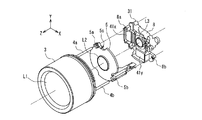
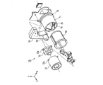
沈胴式のレンズ鏡筒1について、図1から図5を用いて説明する。図示したように、沈胴式レンズ鏡筒の光軸をZ軸(物体側を正とする)とするXYZ3次元直交座標系を設定する。L1は1群レンズ、L2は光軸(Z軸)上を移動して変倍を行う2群レンズ、L3は像ぶれ補正用の3群レンズ、L4は変倍に伴う像面変動の補正及び合焦のために光軸上を移動する4群レンズである。
The
1群保持枠2は1群レンズL1を保持しており、1群レンズL1の中心軸が光軸と平行となるように、筒状の1群移動枠3に対してネジ等で固定されている。この1群移動枠3には、光軸と平行な2本のガイドポール(ガイド部材)4a,4bの一端が固定されている。
The first
2群移動枠5は2群レンズL2を保持し、先述の2本のガイドポール4a,4bによって支持されることにより、光軸方向に摺動可能となっている。また2群移動枠5は、ステッピングモータなどの2群レンズ駆動アクチュエータ6の送りネジ6aと、2群移動枠5に設けたラック7のネジ部とが噛合することにより、2群レンズ駆動アクチュエータ6の駆動力にて、光軸方向に移動して変倍を行う。
The second
3群枠8は、像ぶれ補正用レンズ群L3(3群レンズ)を保持し、像ぶれ補正装置31を構成している。
The
4群移動枠9は、3群枠8とマスターフランジ10との間に挟まれた、光軸と平行な2本のガイドポール11a,11bにて支持されることにより、光軸方向に摺動可能となっている。また4群移動枠9は、ステッピングモータなどの4群レンズ駆動アクチュエータ12の送りネジ12aと、4群移動枠9に設けたラック13のネジ部とが噛合することにより、4群レンズ駆動アクチュエータ12の駆動力にて、光軸方向に移動し、変倍に伴う像面変動の補正と合焦とを行う。
The fourth
撮像素子(CCD)14は、マスターフランジ10に取り付けられている。
The image sensor (CCD) 14 is attached to the
次に、ガイドポール4a,4bの支持方法について、図2を用いて説明する。
Next, a method for supporting the
3群枠8には支持部8a(主軸側),8b(廻り止め側)が設けられている。ガイドポール4a,4bが支持部8a,8bを貫入することにより、ガイドポール4a,4bは光軸と平行に保持される。この2つの支持部8a,8bに対してガイドポール4a,4bが光軸方向に摺動するため、ガイドポール4a,4bの一端に固定された1群移動枠3に保持された1群レンズL1は、3群枠8に設けられた像ぶれ補正用レンズL3に対して精度が保たれる。さらに、ガイドポール4a,4bが、2群移動枠5に設けられた支持部5a(廻り止め側),5b(主軸側)を摺動可能に貫入することにより、2群移動枠5はガイドポール4a,4bに光軸方向に摺動自在に支持されるため、2群移動枠5に保持された2群レンズL2は、3群枠8に設けられた像ぶれ補正用レンズL3に対して精度が保たれる。
The
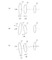
ここで、上記に説明した1群レンズL1,2群レンズL2,3群レンズL3の関係を、図3(a)〜図3(c)を用いて説明する。図中、矢印L1a,L2aは、それぞれ1群レンズL1,2群レンズL2の中心軸の向きを示している。 Here, the relationship between the first group lens L1, the second group lens L2, and the third group lens L3 described above will be described with reference to FIGS. 3 (a) to 3 (c). In the figure, arrows L1a and L2a indicate the directions of the central axes of the first group lens L1 and the second group lens L2, respectively.
図3(a)は3つのレンズ群L1,L2,L3の理想状態を示しており、Z軸(レンズ鏡筒の光軸であり、これは3群レンズL3の中心軸と一致する)に対して1群レンズL1の中心軸L1a及び2群レンズL2の中心軸L2aが平行になっている。 FIG. 3A shows an ideal state of the three lens groups L1, L2, and L3, with respect to the Z axis (the optical axis of the lens barrel, which coincides with the central axis of the third group lens L3). The central axis L1a of the first group lens L1 and the central axis L2a of the second group lens L2 are parallel to each other.
図3(b)は図30に示す従来のレンズ鏡筒と同様の方式により、1群レンズL1及び2群レンズ群L2を、図30の移動レンズ枠72に設けたカムピン72a及び移動レンズ枠73に設けたカムピン73aによりそれぞれ支持した場合を示している。この場合、カムピン72a,73a及びカム溝74,75の精度のばらつきにより、1群レンズL1の中心軸L1a及び2群レンズL2の中心軸L2aは、相互に平行ではなく、且つZ軸とも平行とはならない。従って、光学性能が悪化する可能性が大きい。
FIG. 3 (b) shows a cam pin 72a and a moving lens frame 73 provided on the moving lens frame 72 of FIG. 30 with the first group lens L1 and the second group lens group L2 in the same manner as the conventional lens barrel shown in FIG. The case where it supports by the cam pin 73a provided in each is shown. In this case, due to variations in accuracy of the cam pins 72a and 73a and the
図3(c)は本実施の形態の場合を示している。1群レンズL1及び2群レンズL2は、同一のガイドポール4a,4bに支持されているため、1群レンズL1の中心軸L1a及び2群レンズL2の中心軸L2aがZ軸に対して仮に傾いたとしても、両中心軸L1a,L2aの向きは常に一致する。すなわち、光学性能に対する影響度が最も高い像ぶれ補正用レンズ群L3に対して1群レンズL1及び2群レンズL2は常に同一方向に傾くため、光学性能の悪化量を最小限に抑えることができる。
FIG. 3C shows the case of this embodiment. Since the first group lens L1 and the second group lens L2 are supported by the
次に、1群レンズL1を光軸方向に移動させる構成について説明する。 Next, a configuration for moving the first group lens L1 in the optical axis direction will be described.
略中空円筒状の駆動枠15の撮像素子14側の内周面の一部にギア15aが形成されている。また、その物体側(Z軸の正の側)の内周面に略120°間隔に3つの突起部15bが形成されている。突起部15bが1群移動枠3の撮像素子14側の外周面に設けられた周方向の3つの溝部3aと係合することにより、駆動枠15は1群移動枠3に対して光軸を中心として相対的に回転可能であり、光軸方向には駆動枠15と1群移動枠3とは一体で移動する。さらに駆動枠15の内周面には、3本のカムピン16a,16b,16cが120°間隔に圧入固定されている。
A
筒状のカム枠17の外表面には、略120゜間隔にて3本のカム溝18a,18b,18cが形成されている。図4に、カム枠17の外周面の展開図を示す。カム枠17のカム溝18a,18b,18cに駆動枠15のカムピン16a,16b,16cがそれぞれ係合する。各カム溝18a,18b,18cは、撮像素子14側(Z軸の負の側)にカム枠17の周方向とほぼ平行な部分19aと、物体側(Z軸の正の側)にカム枠17の周方向とほぼ平行な部分19cと、部分19aと部分19cとを螺旋状に繋ぐ部分19bとを有する。カムピン16a,16b,16cが、部分19aにあるとき、1群レンズL1は撮像素子14側に繰り込まれた状態(沈胴状態)で停止する。この状態から、駆動枠15が光軸回りに回転することにより、カムピン16a,16b,16cは部分19bを経て、部分19cに至る。カムピン16a,16b,16cが部分19cにあるとき、1群レンズL1は物体側に繰り出されて停止する。
Three
カム枠17の外周面であって、カム溝18bとカム溝18cとの間には、スプライン状の駆動ギア19の両端の駆動ギア軸20を回転可能に保持する軸受け部17dと、駆動ギア19との干渉を避けるために半円筒面状に窪ませた駆動ギア取り付け部(凹部)17aとが形成されており、これにより駆動ギア19はカム枠17の外周面上に回転自在に保持されている。駆動ギア19は、後述するマスターフランジ10に取り付けられた駆動ユニット21の駆動力を駆動枠15に設けられたギア部15aに伝達する。したがって、駆動ギア19が回転することにより、駆動枠15が光軸の回りに回転し、この際、駆動枠15に設けられたカムピン16a,16b,16cが、カム枠17のカム溝18a,18b,18c内を移動することにより、駆動枠15は光軸方向にも移動する。このとき、1群移動枠3は、これに固定された2本のガイドポール4a,4bが3群枠8の支持部8a,8bに貫入されていることにより、光軸回りの回転が制限されるから、駆動枠15が光軸方向に移動するに従って、1群移動枠3は光軸方向に直進移動する。
Between the
2群移動枠5の駆動アクチュエータ6は、カム枠17の取り付け部17bに固定される。また、4群移動枠9の駆動アクチュエータ12は、マスターフランジ10の取り付け部10aに固定される。駆動ギア19に駆動力を伝達する駆動ユニット21は、駆動アクチュエータ22と複数のギアからなる減速ギアユニット23とからなり、マスターフランジ10の取り付け部10bに固定される。
The
シャッターユニット24は、撮像素子14の露光量及び露光時間を制御するため、一定の開口径を形成する絞り羽根とシャッター羽根とから構成されている。
The
2群移動枠5用の原点検出センサ25は、発光素子および受光素子からなる光検出センサであり、2群移動枠5の光軸方向の位置、つまり2群レンズL2の原点位置(絶対位置)を検出する。この原点検出センサ25は、図5に示すように、カム枠17の取り付け部17cに取り付けられ、2群移動枠5が最も撮像素子14側(−Z方向側)の位置又はその近傍に移動した際に、2群移動枠5に設けられた羽根5cが原点検出センサ25の正面を通り、光を遮ることにより原点位置を検出する。原点が検出されるとき、2群移動枠5及び2群移動枠に取り付けられたラック7は、駆動モータ6寄りの最も撮像素子14側に位置する。この状態は、後述する図10の状態に該当する。
The
4群移動枠9用の原点検出センサ26は、4群移動枠9の光軸方向の位置、つまり4群レンズL4の原点位置を検出する。駆動枠15用の原点検出センサ27は、駆動枠15の回転方向の位置、つまり駆動枠15と一体で移動する1群移動枠3及び1群レンズL1の原点位置を検出する。
The
像ぶれ補正装置31は、撮影時に像ぶれを補正するための像ぶれ補正用レンズ群L3を、第1の方向(Y方向)であるピッチング方向と、第2の方向(X方向)であるヨーイング方向とに移動させる。第1の電磁アクチュエータ41yはY方向の駆動力を発生し、第2の電磁アクチュエータ41xはX方向の駆動力を発生することにより、像ぶれ補正用レンズ群L3は光軸Zにほぼ垂直なX,Yの2方向に駆動される。
The image
次に、この沈胴式レンズ鏡筒を搭載した撮像装置(ここではDSC35)のアクチュエータ駆動回路について、図6を用いて説明する。 Next, an actuator drive circuit of an imaging apparatus (here, DSC 35) equipped with the retractable lens barrel will be described with reference to FIG.
DSC35には、DSC35を制御するマイクロコンピュータ36が搭載されている。このマイクロコンピュータ36は、DSC35に設けられた電源ボタン37からの信号に基づき、駆動制御手段40を介して1群レンズ駆動アクチュエータ22を駆動制御し、原点検出センサ27が1群レンズL1の原点位置を検出後、所定位置まで1群レンズL1を駆動する。また、マイクロコンピュータ36は、変倍用レバー38からの信号に基づき、駆動制御手段41を介して2群レンズ駆動アクチュエータ6を駆動制御し、原点検出センサ25が2群レンズL2の原点位置を検出後、所定のズーム位置まで2群レンズL2を駆動する。さらに、マイクロコンピュータ36は、シャッターボタン39が押されると、駆動制御手段42を介して4群レンズ駆動アクチュエータ12を駆動制御し、原点検出センサ26が4群レンズL4の原点位置を検出後、焦点合わせを行う。
The
撮影モード選択ダイヤル53は、図9に示すように、DSC35に設けられた回転式のダイヤルである。この撮影モード選択ダイヤル53を回転させて、基準位置53aに各モードを示した絵文字を一致させることにより、各モードを選択できる。この撮影モード選択ダイヤル53には、静止画撮影モードとして、プログラムモード「P」53b、絞り優先モード「A」53c、シャッター優先モード「S」53dを備え、更に、動画撮影モード53e、撮影画像再生モード53f、撮影画像送信モード53gを備える。
The shooting
次に、DSC35の画像処理回路について、図7を用いて説明する。
Next, the image processing circuit of the
撮像素子(CCD)14は、沈胴式レンズ鏡筒1を介して入射する映像を電気信号に変換し、撮像素子駆動制御手段43によりその動作が制御される。アナログ信号処理手段44は、撮像素子14により得られた映像信号に対し、ガンマ処理などのアナログ信号処理を施す。A/D変換手段45は、アナログ信号処理手段44から出力されたアナログの映像信号をデジタル信号に変換する。デジタル信号処理手段46は、A/D変換手段45によりデジタル信号に変換された映像信号に対し、ノイズ除去や輪郭強調等のデジタル信号処理を施す。フレームメモリ47は、デジタル信号処理手段46を経た画像信号を一旦記憶する。画像記録制御手段48は、フレームメモリ47で一旦記憶された画像の、内部メモリあるいは記録メディア等の画像記録手段49への書き込みを制御する。画像記録手段49に記録された撮影画像は、画像表示制御手段50からの信号により、フレームメモリ51を介して、DSC35に搭載された液晶モニタ等の画像表示装置52に表示される。
The image pickup device (CCD) 14 converts an image incident through the
このように構成されたDSC35について、その動作を以下に述べる。
The operation of the
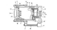
最初に、沈胴式のレンズ鏡筒1が、図10に示す非撮影時(未使用時)の状態から、図11、図12に示す撮影時の状態に移行し、DSC35として撮影が可能となるまでの動作について、図13に示すフローチャートを用いて説明する。
First, the
まず、動画像を撮影する際には、撮影モード選択ダイヤル53により、動画撮影モード53eを選択する(S101)。このとき、レンズ鏡筒1は図10の非撮影時の状態である。電源ボタン37を押して、DSC35本体の電源をオンにする(S102)。電源がオンになることにより、最初に1群レンズL1を駆動する1群レンズ駆動アクチュエータ22が回転し、減速ギアユニット23を介して駆動ギア19を回転させる。そして、駆動ギア19が回転することにより、駆動ギア19と噛合している駆動枠15が、カム溝18a,18b,18cに沿って光軸を中心として回転する。そして原点検出センサ27を初期化した後、駆動枠15が物体方向(Z軸方向)に移動することにより、1群移動枠3も物体方向に移動する。そして、1群レンズ駆動アクチュエータ22が所定の回転量だけ回転したのを図示せぬ回転量検出センサが検出すると、1群移動枠3が所定の位置まで移動した後、1群レンズ駆動アクチュエータ22の回転が停止する。この停止位置では、図4のカム溝の展開図において、カムピン16a,16b,16cは、カム枠17の周方向とほぼ平行な部分19cに到達している。図11はこのときの状態を示している。
First, when shooting a moving image, the moving
次に、ズーミング用レンズである2群レンズL2を所定位置に移動させるため、2群レンズ駆動アクチュエータ6が回転し、送りネジ6aを介してラック7を駆動することにより、2群移動枠5がZ軸に沿って動き出す。
Next, in order to move the second group lens L2 which is a zooming lens to a predetermined position, the second group
ここで、DSC35のマイクロコンピュータ36に、電源オン後のズーム倍率の初期位置が広角端付近に設定されている場合には、2群移動枠5は、原点検出センサ25を初期化した後、図12に示す広角端付近にて停止し、DSC35は撮影準備状態となる。
Here, in the
次にマイクロコンピュータ36は、撮影モード選択ダイヤル53が、動画撮影モード53eになっているかどうかを判断する(S103)。動画撮影モード53eが選択されている場合には、自動的に動画撮影を開始する(S105)。一方、静止画撮影モード53b〜53dが選択されている場合には、撮影スタンバイ状態となり、撮影者の次の指示を待つ。動画撮影を終了する際には、シャッターボタン39を全押しする(S106)。これにより、動画撮影が終了し、撮影スタンバイ状態となる。撮影スタンバイ状態において、撮影者がシャッターボタン39を全押しすることにより、撮影モード選択ダイヤル53の状態に応じて、静止画像あるいは再び動画像の撮影を行うことができる。
Next, the
撮影時のズーミング動作については、ズーミング用レンズである2群レンズL2を、図12に示す広角端の位置から図11に示す望遠端の位置まで移動させることにより、任意のズーム位置にて撮影可能である。 Regarding the zooming operation at the time of shooting, it is possible to shoot at any zoom position by moving the second lens group L2 which is a zooming lens from the wide-angle end position shown in FIG. 12 to the telephoto end position shown in FIG. It is.
ここで、上記のいずれの場合においても、1群移動枠3および2群移動枠5は、3群枠8の支持部8a,8bに保持された同一のガイドポール4a,4bにて支えられながら所定位置まで移動する。したがって、1群レンズL1および2群レンズL2が光軸に対して傾いたとしても、それらの傾き方向は像ぶれ補正用レンズ群L3に対して同一であるため、所定の光学性能を確保することができる。
Here, in any of the above cases, the first
次に図11、図12に示す各撮影時の状態から、図10に示す非撮影時の状態に移行する際の動作について説明する。 Next, the operation at the time of transition from the state at each photographing shown in FIGS. 11 and 12 to the state at the non-photographing shown in FIG. 10 will be described.
それぞれの撮影時の状態より、DSC35の電源ボタン37がオフされると撮影が終了し、最初に2群移動枠5が2群レンズ駆動アクチュエータ6により撮像素子14側に移動して、図11に示す状態となる。次に1群レンズ駆動アクチュエータ22が回転し、減速ギアユニット23を介して駆動ギア19を上記とは逆方向に回転させる。駆動ギア19が回転することにより、駆動ギア19と噛合している駆動枠15が光軸を中心として回転し、同時に、カム溝18a,18b,18cによって撮像素子14方向に移動することにより、1群移動枠3も移動する。そして原点検出センサ27により駆動枠15の回転を検出すると、1群移動枠3が所定の位置まで移動した後、1群レンズ駆動アクチュエータ22の回転が停止する。この停止位置では、図4のカム溝の展開図において、カムピン16a,16b,16cは、カム枠17の周方向とほぼ平行な部分19aに到達している。これにより、図10に示す状態に移行し、撮影時の状態に比べて長さcだけ短くなった沈胴状態となる。
When the
ここで、沈胴式レンズ鏡筒1の光軸方向の長さを変える沈胴動作については1群レンズL1を駆動する1群レンズ駆動アクチュエータ22を用い、ズーミング動作については2群レンズ駆動アクチュエータ6を単独で使用している。そのため、実際の撮影でのズーミング動作は、1群レンズL1を繰り出した状態で行うため、1群レンズ駆動アクチュエータ22を動作させる必要はなく、2群レンズ駆動アクチュエータ6のみを駆動して図11から図12の任意の位置に2群レンズL2を移動させてズーミングを行うことができる。したがって、ズーミング動作を行うなどの撮影を行う際には、図30に示した従来方式の沈胴式レンズ鏡筒とは異なり、ズーム倍率に応じて、鏡筒の繰り出し動作及び繰り込み動作を行う必要がない。図30の従来の沈胴式のレンズ鏡筒においては、ズーミング動作時に、1つの駆動アクチュエータ79を回転させ、減速ギアトレイン78を介してカム筒71を回転させて、移動レンズ枠72,73を同時に駆動していたため、ズーミング速度が遅く、駆動音が大きい。本発明の沈胴式のレンズ鏡筒1は、2群レンズ駆動アクチュエータ6としてステッピングモータを使用し、そのステッピングモータに取り付けられた送りネジ6aを介して、2群移動枠5を直接駆動するため、送り速度も速く、動作音も小さい。したがって、撮影者は瞬時に画角を変更することが可能となり、被写体を追いかける、音声付きの動画を撮影するなど、従来のDSCでは不向きであった使用方法を行うことができる。
Here, for the collapsing operation for changing the length of the
以上のように実施の形態1によれば、動画像と静止画像との両方を撮影することができるDSCにおいて、動画撮影モードが選択された状態で、DSCの電源をオンにすると、自動的に動画撮影が開始する。従って、被写体を追いかけて、瞬時に動画撮影を開始できるという動画撮影に最適なDSCとすることができる。 As described above, according to the first embodiment, in a DSC that can shoot both moving images and still images, when the moving image shooting mode is selected and the DSC is turned on automatically, Movie recording starts. Therefore, it is possible to obtain an optimum DSC for moving image shooting, in which moving image shooting can be started instantaneously after chasing the subject.
さらに、高倍率対応のレンズを搭載したDSCにおいて、1群レンズL1及び2群レンズL2が、像ぶれ補正用レンズL3に対し、少なくとも同一方向に傾くように構成したことにより、光学性能の低下量を最小限に抑えつつ、未使用時の全長を短くすることが可能となるという顕著な効果が得られる。 Further, in the DSC equipped with a lens corresponding to a high magnification, the first group lens L1 and the second group lens L2 are configured to be inclined at least in the same direction with respect to the image blur correction lens L3. The remarkable effect that it becomes possible to shorten the full length when not in use while minimizing the above is obtained.
なお、3群レンズL3については、像ぶれ補正装置31を用いて光軸と直交する方向に移動可能としたが、3群レンズL3が3群枠8に固定された、像ぶれ補正装置を搭載しない一般のレンズ鏡筒を用いても、同様の効果が得られることは言うまでもない。
Although the third group lens L3 can be moved in the direction orthogonal to the optical axis by using the image
なお、本実施の形態1においては、動画撮影モードが選択されている場合には、電源オン時に、自動的に動画撮影が開始される構成としたが、メニューの選択操作により、撮影者がシャッターボタンを押すまでは動画撮影が開始されないように構成することもできる。この場合には、不用意に電源を入れてしまい、動画撮影が開始されてしまうという誤動作を回避することができる。 In the first embodiment, when the moving image shooting mode is selected, the moving image shooting is automatically started when the power is turned on. It can also be configured so that video recording does not start until the button is pressed. In this case, it is possible to avoid a malfunction that the power is inadvertently turned on and the moving image shooting is started.
(実施の形態2)
次に、本発明の実施の形態2における撮像装置について、図14を用いて説明する。図14は実施の形態2における撮像装置の撮影動作を説明するフローチャートである。なお、実施の形態1と同一の構成要素については同一の符号を付し、その説明を省略する。
(Embodiment 2)
Next, an imaging apparatus according to
以下、図14に示すフローチャートを用いて、その動作を述べる。まず、DSC35本体の電源をオンにする(S201)ことにより、DSC35は撮影スタンバイ状態となる(S202)。次に動画撮影を行う場合には、撮影モード選択ダイヤル53にて動画撮影モード53eを選択する(S203)。動画撮影モード53eが選択された場合には、自動的に動画撮影を開始する(S204)。この場合、シャッターボタン39などを押す必要はなく、瞬時に動画撮影が開始する。動画撮影を終了させる場合には、シャッターボタン39を全押しすることにより(S205)、撮影が終了する。
The operation will be described below using the flowchart shown in FIG. First, by turning on the power of the
以上のように実施の形態2によれば、動画像と静止画像との両方を撮影することができるDSCにおいて、電源オンの状態で動画撮影モードが選択された場合、自動的に動画撮影が開始する。従って、動画撮影の開始のために別途シャッターボタンなどを押す必要がなく、瞬時に動画撮影を開始させることができる。その結果、大事なシャッターチャンスを逃す機会を減らすことができる。 As described above, according to the second embodiment, in the DSC capable of shooting both moving images and still images, when the moving image shooting mode is selected while the power is on, moving image shooting starts automatically. To do. Therefore, there is no need to press a separate shutter button or the like to start moving image shooting, and moving image shooting can be started instantaneously. As a result, the chance of missing important shutter opportunities can be reduced.
なお、本実施の形態2においては、動画撮影モードが選択された場合には、自動的に動画撮影が開始される構成としたが、メニューの選択操作により、撮影者がシャッターボタンを押すまでは動画撮影が開始されないように構成することもできる。この場合には、不用意に撮影モード選択ダイヤルを廻してしまい、動画撮影が開始されてしまうという誤動作を回避することができる。 In the second embodiment, the moving image shooting is automatically started when the moving image shooting mode is selected. However, until the photographer presses the shutter button by the selection operation of the menu. It can also be configured not to start moving image shooting. In this case, it is possible to avoid a malfunction that the shooting mode selection dial is inadvertently turned to start moving image shooting.
(実施の形態3)
次に、本発明の実施の形態3における撮像装置について、図15を用いて説明する。図15は実施の形態3における撮像装置の撮影動作を説明するフローチャートである。なお、実施の形態1と同一の構成要素については同一の符号を付し、その説明を省略する。
(Embodiment 3)
Next, an imaging apparatus according to
以下、図15に示すフローチャートを用いて、その動作を述べる。まず、動画像を撮影する際には、撮影モード選択ダイヤル53により、動画撮影モード53eを選択する(S301)。このとき、レンズ鏡筒1は図10の非撮影時の状態である。電源ボタン37を押して、DSC35本体の電源をオンにする(S302)。電源がオンになることにより、1群レンズアクチュエータ22、2群レンズアクチュエータ6が回転し、1群レンズL1、2群レンズL2が所定量光軸Z方向に移動して、図12に示す広角端付近にて停止し、DSC35は撮影準備状態となる。
The operation will be described below using the flowchart shown in FIG. First, when shooting a moving image, the moving
次にマイクロコンピュータ36は、撮影モード選択ダイヤル53が、動画撮影モード53eになっているかどうかを判断する(S303)。動画撮影モード53eが選択されている場合には、次のステップ(S305)に移行し、静止画撮影モード53b〜53dが選択されている場合には、撮影スタンバイ状態となる(S304)。次に、動画撮影モード53eが選択されている場合において、シャッターボタン39が全押しされると(S305)、動画撮影を開始する前に、少なくとも1枚の静止画像を撮影する(S306)。この静止画像は、フレームメモリ47を経由して、画像記録手段49を介してメモリカード等の記録媒体へ書き込まれ、静止画像の撮影を終了する(S307)。静止画像の撮影が終了すると、自動的に動画撮影モードに移行し、動画撮影を開始する(S308)。動画撮影を終了する場合には、シャッターボタン39を全押しする(S309)。これにより、動画撮影が終了し、撮影スタンバイ状態となる。
Next, the
以上のように実施の形態3によれば、動画像と静止画像との両方を撮影することができるDSCにおいて、動画撮影モードが選択された状態で動画撮影を行うと、動画撮影の開始の直前に、その動画像に比べ高解像度の静止画像を撮影するので、同一の時刻の被写体を連続して撮影できるという顕著な効果が得られる。つまり、これまでの沈胴式レンズ鏡筒付きDSCでは音声付き動画像と静止画像とを同時刻に撮影できないという課題を解決することができる。 As described above, according to the third embodiment, in a DSC capable of shooting both moving images and still images, when moving image shooting is performed with the moving image shooting mode selected, immediately before the start of moving image shooting. In addition, since a still image having a higher resolution than that of the moving image is taken, a remarkable effect that a subject at the same time can be taken continuously can be obtained. That is, the conventional DSC with a retractable lens barrel can solve the problem that a moving image with sound and a still image cannot be taken at the same time.
なお、動画撮影開始前の静止画像の撮影は、1枚に限ることはなく、複数枚の連写を行っても良い。 Note that the shooting of still images before the start of moving image shooting is not limited to one, and a plurality of continuous shooting may be performed.
(実施の形態4)
次に、本発明の実施の形態4における撮像装置について、図16〜図18を用いて説明する。図16は実施の形態4における撮像装置のファイルシステムのディレクトリ構造を示す図、図17は同撮像装置の関連付け情報ファイルのデータを説明する図、図18は同撮像装置の撮影動作を説明するフローチャートである。なお、実施の形態1と同一の構成要素については同一の符号を付し、その説明を省略する。
(Embodiment 4)
Next, an imaging apparatus according to
図16、図17を用いて、DSC35の撮影画像のファイル管理方法について説明する。撮影した撮影画像が記録される記録メディア(図示せず)には、撮影画像フォルダ54(フォルダ名“Picture”)が形成され、その下に関連付け情報ファイルフォルダ55(フォルダ名“Index”)、静止画像フォルダ56(フォルダ名“Still”)、動画像フォルダ57(フォルダ名“Movie”)が形成される。静止画像フォルダ56には、撮影された静止画像が保存される静止画像ファイル59が、例えば、“Still001.jpg”という名前でファイル作成される。動画像フォルダ57には、撮影された動画像が保存される動画像ファイル60が、例えば、“Movie001.avi”という名前でファイル作成される。さらに、関連付け情報ファイルフォルダ55には、撮影された動画像と静止画像とを関連付けるための関連付け情報が保存される関連付け情報ファイル58が、例えば“Index001.html”という名前でファイル作成される。すなわち、この“Index001.html”というファイルには、図17に示すように、静止画像ファイル59の“Still001.jpg”と、動画像ファイル60の“Movie001.avi”とのディレクトリ上での相対パス(即ち、関連付け情報)が記録されることにより、同時刻に撮影された静止画像と動画像との関連付けを実現している。
A file management method for captured images of the
以下、図18に示すフローチャートを用いて、その動作を述べる。まず、動画像を撮影する際には、撮影モード選択ダイヤル53により、動画撮影モード53eを選択する(S401)。このとき、レンズ鏡筒1は図10の非撮影時の状態である。電源ボタン37を押して、DSC35本体の電源をオンにする(S402)。電源がオンになることにより、1群レンズアクチュエータ22、2群レンズアクチュエータ6が回転し、1群レンズL1、2群レンズL2が所定量光軸Z方向に移動して、図12に示す広角端付近にて停止し、DSC35は撮影準備状態となる。
The operation will be described below using the flowchart shown in FIG. First, when shooting a moving image, the moving
次にマイクロコンピュータ36は、撮影モード選択ダイヤル53が、動画撮影モード53eになっているかどうかを判断する(S403)。動画撮影モード53eが選択されている場合には、次のステップ(S405)に移行し、静止画撮影モード53b〜53dが選択されている場合には、撮影スタンバイ状態となる(S404)。次に、動画撮影モード53eが選択されている場合において、シャッターボタン39が全押しされると(S405)、動画撮影を開始する前に、少なくとも1枚の静止画像を撮影する(S406)。この静止画像は、フレームメモリ47を経由して、画像記録手段49を介してメモリカード等の記録媒体へ書き込まれ、静止画像の撮影を終了する(S407)。この際、メモリカード等に初めて記録される場合には、静止画像フォルダ56を作成後、その階層下に静止画像ファイル59として“Still001.jpg”を作成し、この中に静止画像が保存される。また、静止画像フォルダ56が既に作成されている場合には、静止画像ファイル59のみを作成し、この中に静止画像が保存される。次に、静止画像の撮影が終了すると、自動的に動画撮影モードに移行し、動画像の撮影を開始する(S408)。動画像の撮影を終了する場合には、シャッターボタン39を全押しする(S409)。これにより、撮影を終了し、撮影スタンバイ状態となる。撮影された動画像は、フレームメモリ47を経由して、画像記録手段49を介してメモリカード等へ書き込まれる。この際、メモリカード等に初めて記録される場合には、動画像フォルダ57を作成後、その階層下に動画像ファイル60として“Movie001.avi”を作成し、この中に動画像が保存される。また、動画像フォルダ57が既に作成されている場合には、動画像ファイル60のみを作成し、この中に動画像が保存される。そして、静止画像ファイル59、動画像ファイル60の記録とともに、関連付け情報ファイルフォルダ55を作成後、その階層下に関連付け情報ファイル58として“Index001.html”が作成され、その中に図17に示した関連付け情報が記録される。
Next, the
以上のように実施の形態4によれば、動画像と静止画像の両方を撮影することができるDSCにおいて、動画像と、その動画撮影の開始直前にその動画像に比べ高解像度の静止画とを撮影することができるとともに、関連付け情報ファイルを作成して、ほぼ同時に作成した動画像と静止画像との関連付けを容易に行うことが出来るので、メモリカード等の記録媒体上でのファイル管理が容易になるという顕著な効果が得られる。 As described above, according to the fourth embodiment, in a DSC that can shoot both moving images and still images, a moving image and a still image with a higher resolution than that of the moving image immediately before the start of moving image shooting. Can be taken, and an association information file can be created to easily associate a moving image and a still image created at almost the same time, so file management on a recording medium such as a memory card is easy. A remarkable effect is obtained.
なお、静止画撮影モード(プログラムモードP53b、絞り優先モードA53c、シャッター優先モードS53d)にて静止画像を撮影した場合には、撮影された静止画像は、静止画像ファイル59が作成されてその中に静止画像が保存される。このとき、対応する関連付け情報ファイル58も同時に作成されるが、動画像ファイル60は作成されない。即ち、図17に示した関連付け情報において動画像ファイル情報はブランクとなる。
When a still image is shot in the still image shooting mode (program mode P53b, aperture priority mode A53c, shutter priority mode S53d), a
(実施の形態5)
次に、本発明実施の形態5における撮像装置について、図19〜図21を用いて説明する。図19は実施の形態5における撮像装置の画像表示部の概略図、図20は同撮像装置における動画像の再生メニューを説明する図、図21は同撮像装置における画像の再生動作を説明するフローチャートである。なお、実施の形態1と同一の構成要素については同一の符号を付し、その説明を省略する。
(Embodiment 5)
Next, an imaging apparatus according to
図19に示すように、DSC35に設けられた画像表示装置52には、撮影された静止画像および動画像を表示することができる。この静止画像および動画像は、DSC35に設けられた上下左右方向に向いた4つの矢印キー64を操作することにより、撮影画像を順番に表示させることができる。
As shown in FIG. 19, captured still images and moving images can be displayed on the
以下、図21に示すフローチャートを用いて、その撮影画像の再生方法について述べる。まず、動画像を再生する際には、撮影モード選択ダイヤル53により、再生モード53fを選択し、メモリカード等より、複数の関連付け情報ファイル58を読み込む(S501)。関連付け情報ファイル58をもとに、画像表示装置52に、例えば、ファイル“Still001.jpg”に保存された静止画像が表示される(S502)。次に、表示された静止画像と同時刻に撮影された動画像を再生するかどうかの選択を行う(S503)。ここで、画像表示装置52に表示されている静止画像に対して、関連付けられた動画像がある場合には、動画像再生メニュー69を一緒に表示する。動画像再生メニュー69は、動画像の再生状態を示す矢印マーク69aと、動画像を再生するためにはどの矢印キー64を操作すればよいのかを示す矢印キーマーク69bとを含む。別の静止画像を表示する場合は、矢印キー64の操作によりページ送りを行い、例えば“Still002.jpg”に保存された静止画像を表示する。動画像を再生する場合には、下方向の矢印キー64(“SET”の文字のある方向)を押すことにより、その時に表示されていた静止画像に関連付けられた動画像の再生を開始する(S504)。例えば、静止画像ファイル“Still001.jpg”に保存されていた静止画像を表示している時に動画再生指示がなされると、関連付け情報ファイル58の“Index001.html”に保存されたデータをもとに、動画像ファイル“Movie001.avi”に保存された動画像の再生を行う(S505)。
Hereinafter, a method for reproducing the captured image will be described with reference to the flowchart shown in FIG. First, when playing back a moving image, the
ここで、静止画像に関連付けられた動画像が存在しない場合、つまり、撮影モード選択ダイヤル53にて、静止画撮影モード(プログラムモードP53b、絞り優先モードA53c、シャッター優先モードS53d)を選択して撮影した静止画像を表示する際には、動画像再生メニュー69を表示しない。この関連付けられた動画像が存在しない静止画像が保存されたファイルは、図16に示す静止画像フォルダ56に保存された静止画像ファイル59のうち、“Still004.jpg”、“Still005.jpg”が該当する。すなわち、これらにそれぞれ対応する“Index004.html”,“Index005.html”という名前の関連付け情報ファイル58は存在するが、これらにそれぞれ対応する“Movie004.avi”、“Movie005.avi”という名前の動画像ファイル60は存在しない。
If there is no moving image associated with the still image, that is, the shooting
また、関連付けられた動画像が存在する静止画像が表示された場合には、画像表示装置52の右上に、動画像が存在することを示すマーク69cが表示される。
In addition, when a still image in which an associated moving image exists is displayed, a
以上のように実施の形態5によれば、動画像と静止画像の両方を撮影することができるDSCにおいて、撮影画像の再生時に、動画像と静止画像との関連付けを行う関連付け情報ファイルを読み込むことにより、静止画像と同時刻に撮影され、かつその静止画像に関連付けられた動画像を、容易に再生することができる。さらに、静止画像にマークをつけることにより、その静止画像に関連付けられた動画像が存在するか否かを瞬時に判断することができるので、動画像の再生が容易になるという顕著な効果が得られる。 As described above, according to the fifth embodiment, in the DSC capable of capturing both moving images and still images, the association information file for associating the moving images with the still images is read when the captured images are reproduced. Thus, it is possible to easily reproduce a moving image that is shot at the same time as the still image and associated with the still image. Further, by marking a still image, it is possible to instantly determine whether or not there is a moving image associated with the still image, so that a significant effect of facilitating the reproduction of the moving image is obtained. It is done.
(実施の形態6)
次に、本発明の実施の形態6における撮像装置について、図22を用いて説明する。図22(a)、図22(b)は実施の形態6における静止画像のサムネイル表示について説明する図である。
(Embodiment 6)
Next, an imaging apparatus according to
実施の形態5において示した図21のフローチャートにおいて、静止画像の表示(S502)を図22に示すようにサムネイル表示とすることもできる。 In the flowchart of FIG. 21 shown in the fifth embodiment, the still image display (S502) may be a thumbnail display as shown in FIG.
画像表示装置52に、1〜9番の静止画像をサムネイル表示させる場合には、図22(b)に示すように、撮影時間順に並べて表示させることが通常である。この場合、実施の形態5にて説明したように、関連付けられた動画像が存在することを示すマーク69cが各画像の右上に表示される。しかしながら、撮影時間順に並べて表示させると、関連付けられた動画像が存在するもの(3〜7番)と関連付けられた動画像が存在しないもの(1〜2番、8〜9番)とが混在して表示されることにより、非常に見にくく、所望の画像を選択しにくい。
When thumbnails of the 1st to 9th still images are displayed on the
これに対して、図22(a)に示すように、撮影画像を並び替え、前半の1〜5番に関連付けられた動画像が存在する静止画像を表示し、後半の6〜9番に関連付けられた動画像が存在しない静止画像を表示する。この撮影画像の並び替えは、画像記録手段49から撮影画像を読み出す際に、画像表示制御手段50及びフレームメモリ51において行う。
On the other hand, as shown in FIG. 22 (a), the captured images are rearranged to display still images in which moving images associated with the first half 1-5 are displayed and associated with the second 6-9. A still image without the displayed moving image is displayed. The rearrangement of the captured images is performed in the image
以上のようにこの実施の形態6によれば、静止画像をサムネイル表示させる際、従来は撮影時間順に表示させていたため見にくかったものを、関連付けられた動画像が存在する静止画像と、関連付けられた動画像が存在しない静止画像とを分類して表示させることにより、動画像の選択、再生が容易になる。 As described above, according to the sixth embodiment, when displaying still images as thumbnails, images that were conventionally difficult to see because they were displayed in order of shooting time are associated with still images that have associated moving images. By classifying and displaying still images that do not have moving images, selection and reproduction of moving images is facilitated.
なお本実施の形態においては、関連付けられた動画像が存在する静止画像と、関連付けられた動画像が存在しない静止画像とを連続して表示したが、さらにわかりやすくするため、その間にブランク画像を挿入するなどしても良い。さらに、サムネイル表示の場合について説明したが、静止画像を表示させる順番を変更することについては、1枚ずつ静止画像を順に表示させる場合に適応しても同様な効果が得られる。 In this embodiment, a still image in which the associated moving image exists and a still image in which the associated moving image does not exist are displayed in succession. It may be inserted. Further, although the case of thumbnail display has been described, the same effect can be obtained by changing the order in which still images are displayed, even if the still images are sequentially displayed one by one.
(実施の形態7)
次に、本発明の実施の形態7における撮像装置について、図23〜図25を用いて説明する。図23は実施の形態7における撮像装置におけるデータ送信部のブロック図、図24は同撮像装置の撮影画像の送信選択メニューを説明する図、図25は同撮像装置の画像の送信動作を説明するフローチャートである。なお、実施の形態1と同一の構成要素については同一の符号を付し、その説明は省略する。
(Embodiment 7)
Next, an imaging apparatus according to
図23は撮像装置に設けられたデータ送信部のブロック図であり、画像送信制御手段61は、画像記録手段49より読み出した撮影画像を、フレームメモリ51を介して、撮影画像送信部62を経て、アンテナ63より送信する。
FIG. 23 is a block diagram of a data transmission unit provided in the imaging apparatus. The image
図24に示すように、画像表示装置52に表示される画像送信選択メニュー66は、静止画像66a、動画像66b、静止画像及び動画像66cの3つのメニューを含み、これらの中から撮影者が送信する画像を選択する。
As shown in FIG. 24, the image
以下、図25に示すフローチャートを用いて、その撮影画像の送信方法について述べる。まず、撮影画像を送信する際には、撮影モード選択ダイヤル53により、送信モード53gを選択し、メモリカード等より、複数の関連付け情報ファイル58を読み込む(S601)。関連付け情報ファイル58をもとに、画像表示装置52に、例えば、“Still001.jpg”ファイに保存された静止画像が表示される(S602)。次に、表示された静止画像、あるいはその静止画像に関連付けられた動画像を送信するかどうかの選択を行う(S603)。ここで、画像表示装置52に表示されている静止画像に対して、関連付けられた動画像がある場合には、図24に示したように、静止画像66a、動画像66b、静止画像及び動画像66cの送信を示す3つのメニューを表示する。別の静止画像を再生する場合は、矢印キー64によりページ送りを行い、例えば“Still002.jpg”ファイルに保存された静止画像を表示する。送信する場合には、どの画像を送信するのかを画像送信選択メニュー66により選択する(S604)。静止画像のみ送信する場合には、例えば、“Still001.jpg”ファイル内の静止画像データを送信する(S605)。また動画像を送信する場合には、関連付け情報ファイル58の“Index001.html”ファイル内のデータをもとに、この静止画像と関連付けられた、例えば、“Movie001.avi”ファイル内の動画像データを送信する(S606)。さらに静止画像と動画像との両方を送信する場合には、関連付け情報ファイル58の“Index001.html”ファイルのデータをもとに、例えば、“Still001.jpg”ファイル内の静止画像データと“Movie001.avi”内の動画像データとの両方を送信する(S607)。
Hereinafter, the transmission method of the captured image will be described using the flowchart shown in FIG. First, when transmitting a photographed image, the
ここで、静止画像に関連付けられた動画像が存在しない場合、つまり、撮影モード選択ダイヤル53にて、静止画撮影モード(プログラムモードP53b、絞り優先モードA53c、シャッター優先モードS53d)を選択して撮影した静止画像を表示する際には、画像送信選択メニュー66に動画像66b、静止画像及び動画像66cの送信を示す2つのメニューは表示せず、静止画像66aの送信を示すメニューのみ表示する。
Here, when there is no moving image associated with the still image, that is, the shooting
なお、撮影画像を送信する場合には、撮影画像と共に、関連付け情報ファイル内のデータを送っても良い。 When transmitting a captured image, the data in the association information file may be transmitted together with the captured image.
また、実施の形態6にて説明したように、静止画像をサムネイル表示してもよい。この場合、静止画像を撮影時間順に並べて表示してもよいが、関連付けられた動画像が存在する静止画像と、関連付けられた動画像が存在しない静止画像とに分類して並べ替えることにより、所望の画像を選択しやすくなる。
In addition, as described in
以上のように実施の形態7によれば、動画像と静止画像の両方を撮影することができるDSCにおいて、撮影画像の送信時に、動画像と静止画像との関連付けを行う関連付け情報ファイルを読み込むことにより、静止画像と同時刻に撮影され、かつその静止画像に関連付けられた動画像を、容易に選択して送信することができる。 As described above, according to the seventh embodiment, in the DSC capable of capturing both moving images and still images, the association information file for associating the moving images with the still images is read when the captured images are transmitted. Thus, it is possible to easily select and transmit a moving image shot at the same time as a still image and associated with the still image.
なお本実施の形態においては、アンテナを含め、画像の送信部を撮像装置に内蔵したが、モデム等のみを内蔵し、携帯電話等と接続して画像を送信する方式としても良い。 In this embodiment, the image transmission unit including the antenna is built in the imaging apparatus. However, only a modem or the like may be built in, and the image may be transmitted by connecting to a mobile phone or the like.
なお本実施の形態においては、撮影画像の送信方式を選択する方式を採用したが、初期設定は自動的にファイル容量の少ない静止画像のみ送信する方式としておき、ユーザが必要なときのみ、動画像を送信可能に変更するような方式にしても良い。 In this embodiment, a method of selecting the transmission method of the captured image is adopted. However, the initial setting is a method of automatically transmitting only a still image with a small file capacity, and a moving image is transmitted only when the user needs it. May be changed so as to enable transmission.
(実施の形態8)
次に、本発明の実施の形態8における撮像装置について、図26〜図29を用いて説明する。図26は実施の形態8における撮像装置のアクチュエータ駆動回路の構成を示したブロック図、図27は同撮像装置のズーム初期位置選択手段の操作パネルを示した概略図、図28は同撮像装置に使用される沈胴式レンズ鏡筒の広角端と望遠端との中間位置での使用時の断面図、図29は同撮像装置の撮影動作を説明するフローチャートである。なお、実施の形態1と同一の構成要素については同一の符号を付し、その説明は省略する。
(Embodiment 8)
Next, an imaging apparatus according to
図26のアクチュエータ駆動回路の構成を示すブロック図は、図6に示す実施の形態1のアクチュエータ駆動回路に対し、ズーム初期位置記憶手段67と、ズーム初期位置選択手段68を追加したものである。ズーム初期位置選択手段68の操作パネルはDSC35の外表面上の操作部に設けられ(図19参照)、その外観は図27に示すように、ズーム位置を選択するための2つの矢印キー68aと、現在のズーム位置を点灯して表示する表示部68bとからなる。使用者が、撮影モード選択ダイヤル53にて、静止画撮影モードあるいは動画撮影モードに設定し、それぞれの撮影モードにて、矢印キー68aを押してズーム位置を選択することにより、電源オン後のズーム位置を、撮影者が自由に選択することができる。選択されたズーム位置は、ズーム初期位置記憶手段67に初期光学ズーム倍率情報として記憶される。
The block diagram showing the configuration of the actuator drive circuit of FIG. 26 is obtained by adding a zoom initial position storage means 67 and a zoom initial position selection means 68 to the actuator drive circuit of the first embodiment shown in FIG. The operation panel of the zoom initial position selection means 68 is provided in the operation unit on the outer surface of the DSC 35 (see FIG. 19). As shown in FIG. 27, the appearance panel includes two
以下、図29に示すフローチャートを用いて、その撮影方法について述べる。 Hereinafter, the photographing method will be described with reference to the flowchart shown in FIG.
まず、静止画像あるいは動画像を撮影する際には、撮影モード選択ダイヤル53により、撮影するモードを選択する(S701)。その状態で、DSC35の電源ボタン37をオンにする(S702)。ここで、マイクロコンピュータ36は、撮影モードがどの状態になっているのかを判別する(S703)。撮影モードが静止画撮影モードである場合、例えば、ズーム初期位置が望遠端に設定されていると、1群レンズL1を駆動する1群レンズ駆動アクチュエータ22が回転し、図11に示す状態に移行する(S704)。
First, when shooting a still image or a moving image, the shooting
また、撮影モードが動画撮影モードである場合、例えば、ズーム初期位置が広角端に設定されていると、1群レンズL1を駆動する1群レンズ駆動アクチュエータ22が回転し、さらにズーミング用レンズである2群レンズL2を所定位置に移動させることにより、図12に示す状態に移行する(S705)。1群レンズL1及び2群レンズL2が所定位置まで移動することにより、撮影準備状態となる(S706)。
Further, when the shooting mode is the moving image shooting mode, for example, when the zoom initial position is set to the wide-angle end, the first group
以上のように本実施の形態8によれば、動画像と静止画像の両方を撮影することができるDSCにおいて、動画撮影時と静止画撮影時との電源オン時のズーム倍率について、撮影者が自由に設定可能としたことにより、例えば、瞬時にズームアップして静止画像を撮影したい場合には、広角端に比べてスタンバイ状態に至るまでの時間が短い望遠端での撮影が電源オンの直後に瞬時に可能になるので、シャッターチャンスを逃すなどの不都合が生じにくくなる。 As described above, according to the eighth embodiment, in the DSC capable of shooting both moving images and still images, the photographer can set the zoom magnification at power-on for moving image shooting and still image shooting. Since it is possible to set freely, for example, if you want to zoom in instantly and shoot a still image, shooting at the telephoto end is shorter than the wide-angle end and it takes less time to reach the standby state. Since it becomes possible instantly, inconveniences such as missing a photo opportunity are less likely to occur.
なお、選択するズーム初期位置については、広角端からから望遠端までの範囲で無段階に設定できるようにしてもよく、例えば、図28に示す広角端と望遠端との中間位置となるようにしても同様な効果が得られる。 Note that the initial zoom position to be selected may be set steplessly in the range from the wide-angle end to the telephoto end. For example, it may be set to an intermediate position between the wide-angle end and the telephoto end shown in FIG. However, the same effect can be obtained.
本発明の利用分野は特に制限はないが、例えばデジタルスチルカメラとして利用することができる。 The field of use of the present invention is not particularly limited, but can be used as, for example, a digital still camera.
L1 1群レンズ
L2 2群レンズ(ズーム用レンズ)
L3 3群レンズ(像ぶれ補正用レンズ群)
L4 4群レンズ(フォーカス用レンズ)
1 沈胴式レンズ鏡筒
2 1群保持枠
3 1群移動枠
4a,4b ガイドポール
5 2群移動枠
6 2群レンズ駆動アクチュエータ
8 3群枠
8a,8b ガイドポール支持部
9 4群移動枠
10 マスターフランジ
11a,11b ガイドポール
12 4群レンズ駆動アクチュエータ
14 撮像素子(CCD)
15 駆動枠
16a,16b,16c カムピン
17 カム枠
18a,18b,18c カム溝
19 駆動ギア
21 駆動ユニット
22 1群レンズ駆動アクチュエータ
23 減速ギアユニット
24 シャッターユニット
25 2群レンズ用原点検出センサ
26 4群レンズ用原点検出センサ
27 1群レンズ用原点検出センサ
31 像ぶれ補正装置
35 DSC
36 マイクロコンピュータ
37 電源ボタン
38 変倍用レバー
39 シャッターボタン
41y,41x 電磁アクチュエータ
52 画像表示装置
53 撮影モード選択ダイヤル
54 撮影画像フォルダ
55 関連付け情報ファイルフォルダ
56 静止画像フォルダ
57 動画像フォルダ
58 関連付け情報ファイル
59 静止画像ファイル
60 動画像ファイル
61 画像送信制御手段
62 撮影画像送信部
63 アンテナ
64 矢印選択キー
66 画像送信選択メニュー
67 ズーム初期位置記憶手段
68 ズーム初期位置選択手段
69 動画再生メニュー
L1 first lens group L2 second lens group (zoom lens)
DESCRIPTION OF
15
36
Claims (7)
前記撮像装置の電源をオン/オフする電源ボタンと、
前記動画撮影モード及び前記静止画撮影モードのいずれかを選択する撮影モード選択手段と、
前記撮像装置が電源オフの状態で前記動画撮影モードが選択された場合には、電源オンの後、直ちに動画撮影の開始を指示する第1の撮影制御手段と
を備えることを特徴とする撮像装置。 An imaging apparatus having a moving image shooting mode for shooting a moving image and a still image shooting mode for shooting a still image,
A power button for turning on / off the imaging device;
Shooting mode selection means for selecting either the moving image shooting mode or the still image shooting mode;
When the moving image shooting mode is selected in a state where the image pickup apparatus is turned off, the image pickup apparatus includes: first shooting control means for instructing to start moving image shooting immediately after the power is turned on. .
前記動画撮影モード及び前記静止画撮影モードのいずれかを選択する撮影モード選択手段と、
前記撮像装置が電源オンの状態で前記動画撮影モードが選択された場合には、直ちに動画撮影の開始を指示する第2の撮影制御手段と
を備えることを特徴とする撮像装置。 An imaging apparatus having a moving image shooting mode for shooting a moving image and a still image shooting mode for shooting a still image,
Shooting mode selection means for selecting either the moving image shooting mode or the still image shooting mode;
An image pickup apparatus comprising: a second image pickup control unit that immediately instructs to start moving image shooting when the moving image shooting mode is selected while the image pickup apparatus is powered on.
前記動画撮影モード及び前記静止画撮影モードのいずれかを選択する撮影モード選択手段と、
前記動画撮影モードにおいては、1回のシャッター操作により、静止画像を少なくとも1枚撮影し、前記静止画像の撮影に連続して動画像を撮影することを指示する第3の撮影制御手段と、
前記動画撮影モード及び前記静止画撮影モードにて撮影された撮影画像を記録する記録手段と、
撮影された動画像を記録するための動画像ファイルを作成する動画像ファイル作成手段と、
撮影された静止画像を記録するための静止画像ファイルを作成する静止画像ファイル作成手段と
を備え、
前記動画撮影モードにおいて撮影された静止画像と前記静止画撮影モードにおいて撮影された静止画像とは、それぞれが記録される静止画像ファイルに連番を含むファイル名が付されて、前記記録手段における同一のフォルダ内に記録されることを特徴とする撮像装置。 An imaging apparatus having a moving image shooting mode for shooting a moving image and a still image shooting mode for shooting a still image,
Shooting mode selection means for selecting either the moving image shooting mode or the still image shooting mode;
In the moving image shooting mode, a third shooting control means for instructing that at least one still image is shot by a single shutter operation and a moving image is shot continuously after shooting the still image;
Recording means for recording a photographed image photographed in the moving image photographing mode and the still image photographing mode;
A moving image file creating means for creating a moving image file for recording the captured moving image;
Still image file creation means for creating a still image file for recording a captured still image;
With
The still image shot in the moving image shooting mode and the still image shot in the still image shooting mode are assigned the same file name including the serial number in the still image file in which the still image is recorded. The image pickup apparatus is recorded in a folder.
前記静止画像の撮影に連続して撮影された動画像が記録されている場合には、前記静止画像に所定のマークを付けて表示する静止画像表示制御手段と、A still image display control means for displaying the still image with a predetermined mark when a moving image taken continuously after the still image is recorded;
静止画像を選択する静止画像選択手段と、Still image selection means for selecting a still image;
前記静止画像選択手段により選択された静止画像と、前記静止画像の撮影に連続して撮影された前記動画像とを、前記表示装置にて再生する動画再生制御手段とMovie reproduction control means for reproducing the still image selected by the still image selection means and the moving image photographed continuously after photographing the still image on the display device;
を備える請求項3に記載の撮像装置。An imaging apparatus according to claim 3.
前記静止画像の撮影に連続して撮影された動画像が記録されている場合には、前記静止画像に所定のマークを付けて表示する静止画像表示制御手段と、
静止画像を選択する静止画像選択手段と、
前記静止画像選択手段により選択された静止画像と、前記静止画像の撮影に連続して撮影された前記動画像とのいずれか一方あるいは両方を送信する送信手段と
を備える請求項3に記載の撮像装置。 Furthermore, a display device that reads out and displays the moving image and the still image from the recording unit;
A still image display control means for displaying the still image with a predetermined mark when a moving image taken continuously after the still image is recorded;
Still image selection means for selecting a still image;
Transmitting means for transmitting either one or both of the still image selected by the still image selecting means and the moving image photographed continuously after photographing the still image;
An imaging apparatus according to claim 3 .
Priority Applications (1)
| Application Number | Priority Date | Filing Date | Title |
|---|---|---|---|
| JP2004153702A JP3816086B2 (en) | 2004-05-24 | 2004-05-24 | Imaging device |
Applications Claiming Priority (1)
| Application Number | Priority Date | Filing Date | Title |
|---|---|---|---|
| JP2004153702A JP3816086B2 (en) | 2004-05-24 | 2004-05-24 | Imaging device |
Related Parent Applications (1)
| Application Number | Title | Priority Date | Filing Date |
|---|---|---|---|
| JP2002370940A Division JP3695752B2 (en) | 2002-12-20 | 2002-12-20 | Imaging device |
Publications (3)
| Publication Number | Publication Date |
|---|---|
| JP2004304831A JP2004304831A (en) | 2004-10-28 |
| JP2004304831A5 JP2004304831A5 (en) | 2006-01-26 |
| JP3816086B2 true JP3816086B2 (en) | 2006-08-30 |
Family
ID=33411279
Family Applications (1)
| Application Number | Title | Priority Date | Filing Date |
|---|---|---|---|
| JP2004153702A Expired - Fee Related JP3816086B2 (en) | 2004-05-24 | 2004-05-24 | Imaging device |
Country Status (1)
| Country | Link |
|---|---|
| JP (1) | JP3816086B2 (en) |
Families Citing this family (2)
| Publication number | Priority date | Publication date | Assignee | Title |
|---|---|---|---|---|
| WO2006115061A1 (en) * | 2005-04-21 | 2006-11-02 | Matsushita Electric Industrial Co., Ltd. | Image pickup device and method for driving image pickup optical system for such image pickup device |
| JP6102558B2 (en) * | 2013-06-20 | 2017-03-29 | ソニー株式会社 | Imaging apparatus, information display method, and information processing apparatus |
-
2004
- 2004-05-24 JP JP2004153702A patent/JP3816086B2/en not_active Expired - Fee Related
Also Published As
| Publication number | Publication date |
|---|---|
| JP2004304831A (en) | 2004-10-28 |
Similar Documents
| Publication | Publication Date | Title |
|---|---|---|
| JP4336387B2 (en) | Imaging device | |
| JP5760164B2 (en) | Camera system and camera body | |
| US7545413B2 (en) | Method and apparatus for displaying images using duplex thumbnail mode | |
| JP2010263254A (en) | Camera system and camera body | |
| JP2009251557A (en) | Imaging apparatus | |
| US20080303936A1 (en) | Camera system | |
| JP4673575B2 (en) | Lens barrel and photographing device | |
| JP4224051B2 (en) | Lens barrel and photographing device | |
| JP2005229291A (en) | Image recording apparatus and imaging apparatus, and image file storage method | |
| JP4954289B2 (en) | Camera system and interchangeable lens | |
| JP4883276B2 (en) | Lens barrel and imaging device | |
| JP3816086B2 (en) | Imaging device | |
| JP3695752B2 (en) | Imaging device | |
| JP2008046200A (en) | Lens barrel and imaging apparatus | |
| JP5486662B2 (en) | Imaging device and camera body | |
| JP2002112097A (en) | Camera | |
| JP2005275351A (en) | Lens barrel and image taking apparatus | |
| JP4339370B2 (en) | Camera, imaging device, lens barrel and camera body | |
| JP3858900B2 (en) | Imaging device | |
| JP4351428B2 (en) | Retractable lens barrel | |
| JP2012118337A (en) | Lens barrel device and image pickup apparatus | |
| JP2007135223A (en) | Imaging apparatus | |
| JP2004053977A (en) | Imaging device | |
| JP5049313B2 (en) | camera | |
| JP2008076511A (en) | Imaging apparatus |
Legal Events
| Date | Code | Title | Description |
|---|---|---|---|
| A521 | Request for written amendment filed |
Free format text: JAPANESE INTERMEDIATE CODE: A523 Effective date: 20051206 |
|
| A621 | Written request for application examination |
Free format text: JAPANESE INTERMEDIATE CODE: A621 Effective date: 20051206 |
|
| A977 | Report on retrieval |
Free format text: JAPANESE INTERMEDIATE CODE: A971007 Effective date: 20060529 |
|
| TRDD | Decision of grant or rejection written | ||
| A01 | Written decision to grant a patent or to grant a registration (utility model) |
Free format text: JAPANESE INTERMEDIATE CODE: A01 Effective date: 20060601 |
|
| A61 | First payment of annual fees (during grant procedure) |
Free format text: JAPANESE INTERMEDIATE CODE: A61 Effective date: 20060606 |
|
| R150 | Certificate of patent or registration of utility model |
Free format text: JAPANESE INTERMEDIATE CODE: R150 |
|
| FPAY | Renewal fee payment (event date is renewal date of database) |
Free format text: PAYMENT UNTIL: 20100616 Year of fee payment: 4 |
|
| FPAY | Renewal fee payment (event date is renewal date of database) |
Free format text: PAYMENT UNTIL: 20100616 Year of fee payment: 4 |
|
| FPAY | Renewal fee payment (event date is renewal date of database) |
Free format text: PAYMENT UNTIL: 20110616 Year of fee payment: 5 |
|
| FPAY | Renewal fee payment (event date is renewal date of database) |
Free format text: PAYMENT UNTIL: 20120616 Year of fee payment: 6 |
|
| FPAY | Renewal fee payment (event date is renewal date of database) |
Free format text: PAYMENT UNTIL: 20130616 Year of fee payment: 7 |
|
| LAPS | Cancellation because of no payment of annual fees |