JP3814395B2 - Sample collection device - Google Patents
Sample collection device Download PDFInfo
- Publication number
- JP3814395B2 JP3814395B2 JP34831297A JP34831297A JP3814395B2 JP 3814395 B2 JP3814395 B2 JP 3814395B2 JP 34831297 A JP34831297 A JP 34831297A JP 34831297 A JP34831297 A JP 34831297A JP 3814395 B2 JP3814395 B2 JP 3814395B2
- Authority
- JP
- Japan
- Prior art keywords
- sample
- solution
- unit
- pump
- sample collection
- Prior art date
- Legal status (The legal status is an assumption and is not a legal conclusion. Google has not performed a legal analysis and makes no representation as to the accuracy of the status listed.)
- Expired - Lifetime
Links
Images


Description
【0001】
【発明の属する技術分野】
この発明は、臨床検査、医療生物学的研究分野、農業林業水産生物学的研究分野及び検査等に於いて、検体採取,分離保存,検査同定等を簡便に行うことができる検体採取器具に関するものである。
【0002】
【従来の技術】
検体採取器具としては、従来、綿棒、木べら、マッチ棒、楊枝、ガラス棒、合成樹脂成型品、ブラシ、刷毛等が、検体に応じて使用されている。
【0003】
少量,微量の検体を採取する合成樹脂成型品に於いては、溝、穴若しくは凹凸を形成したり、小径の筒状に形成し、その凹凸部若しくは小径の孔に検体を留置している。
【0004】
又、綿棒、ブラシ、刷毛等に於いては、その繊維間に検体を留置している。
【0005】
【発明が解決しようとする課題】
上記従来の器具では、採取した検体を溶解液中に溶解させる際、検体が容易に器具から分離されない欠点があった。自然に分離させているが、これでは十分な溶解が得られないので、正確に検体を少量採取しても、当初の目的が達成されない場合もあった。
【0006】
また、溶解液を器具から取り出す際、不溶解物を分離するため濾過材を通す場合があるが、濾過材が限られた面積のため目詰まりを起こす問題があった。そのため取り出すことが不可能となり、器具そのものを廃棄せざるを得なくなり、再度採取しなければならない場合があった。再度採取することは、非能率的であるだけでなく検体採取時の再現性を著しく損なうものであった。
【0007】
更に、従来の採取器具は、検体そのものを分取する形で採取するので、少量の検体の採取には不適な欠点があった。
従って、従来の採取器具は、未だ十分満足すべきものではなかった。
【0008】
この発明は、このような点に着目してなされたものであり、検体が溶解液に容易に溶解すると共に濾過面積を広く取ることができ、目詰まりを防止できる検体採取器具を提供することを目的とする。
【0009】
【課題を解決するための手段】
上記目的に沿う本発明の構成は、通気性を有する素材により形成された検体採取部と該採取部に直接若しくは連結管を介して連設されたポンプ部とを具備して成り、採取付着した検体を前記ポンプ部で圧搾された空気により、溶解液中に剥離溶解し得るように構成したことを特徴とする。
【0010】
前記検体を溶解させた溶液は、濾過機能を兼備した検体採取部を通って前記ポンプ部に吸引留置し、ポンプ部に形成した排出部を開封することによって、前記濾過された溶液を取り出すように形成している。
【0011】
【発明の実施の形態】
次に、本発明の実施の形態を図面に基づいて説明する。
図に示す実施例は、大腸癌の集団検診に用いられる採便容器としての例である。
【0012】
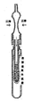
図1に示すように、検体採取器5は、弾性材料から筒状に形成したポンプ部1と、該ポンプ部1に連設した小径の筒状体2と、該筒状体2の先端に装着した検体採取部3と、筒状体2に形成した密嵌部(ネジ部若しくは凸状)に密嵌する容器部4とから構成されている。
【0013】
ポンプ部1は、押しつぶして空気を吐出し、膨らませて空気を吸引し得るようなゴム若しくは軟質プラスチックから形成されている。
【0014】
上記実施例では、ポンプ部1に小径の筒状体(連結管)2を密嵌溶着させているが、これは一体的に形成しても勿論良い。上記実施例では、小径の筒状体の後端には、大径の筒状体10が連設され、該筒状体10にポンプ部1を密嵌装着させている。
【0015】
検体採取部3の材質としては、連続気泡の発泡体、焼結プラスチック、焼結セラミック等のように通気性及び水不溶性で十分な強度のあるものであればどのようなものでも差し支えない。
【0016】
検体採取部3の材質としては、特に選別濾過機能を有するものが良い。例えば、上記連続気泡の発泡体等の気孔率、剛性、化学処理等を選択して、使用目的に応じた選別濾過機能を付与させると良い。
【0017】
採取部3の形状は、採取する検体の性状に応じて、種々の適切な形状に形成すると良い。
本発明の採取部3は、通気性があるので、液状検体を吸引,絡め取ることができ、また採取部3の硬度,形状を選択することによって、固化検体の内外部を採取することができる。
【0018】
検体採取器5には、容器部(キャップ)6が嵌合若しくは螺合等によって、密栓(密嵌)状態となるようになっている。このように形成することによって、ポンプ部1に所定量の溶液を吸引した後、容器部6を密嵌させることによって、溶液を留置できる。
【0019】
上記実施例では、連結管5に形成したねじ部若しくは凸条8に、容器部6を密嵌し得るように形成しているが、密栓できるなら必ずしもこのようでなくとも良い。
【0020】
容器部6は、図2に示すように、予め溶解液を充填した状態としておくのが良いが、図1に示すように単に検体採取部3の衛生性保護のためのキャップとし、使用時に溶解液を充填させるようにしても良い。
【0021】
検体採取部3は、連結部2に圧入嵌合させて一体的に連結している。ポンプ部1による加減圧に耐えるなら、連結手段は特に限定されない。
【0022】
ポンプ部1の他端には、小径のパイプ状の滴下部9が形成されている。この滴下部9の先端を切断若しくは穿孔して、ポンプ部1に留置した溶液を滴下するようになっている。
【0023】
滴下部9は、単に薄肉部に形成して、穿孔して開口するようにしても勿論差し支えない。
【0024】
次に、上記のように構成された本発明の検体採取器具の使用方法を説明する。まず、図3に示すように、ポンプ部1を手で持って検体採取部3を検体(本実施例では糞便)に刺すか或は検体表面を擦する。液状便の場合は、表面に吸収させる。
【0025】
次いで、図4に示すように、引き上げる。検体採取部に検体が付着するが、余剰の検体は、紙等で拭き取る。
【0026】
それから、図2に示す溶解液の収容された容器部4の口部7から蓋体6を引き抜いて、図5に示すように、容器部4の口部7から検体採取器5を挿入する。
【0027】
図6及び図7に示すように、検体採取部3を溶解液中に没入させた状態で、ポンプ部1の圧搾、開放を繰り返す。圧搾することによって空気と共に剥離された検体は、溶解液に溶解し、開放することによって、検体を溶解した液体が、検体採取部3で濾過され、ポンプ部1内に吸入される。
【0028】
ポンプ部1内に十分量の検体を吸入したところで、図8に示すように、容器部4を検体採取器5の密栓部(ネジ部若しくは凸状)8に密嵌若しくは螺合して、連結密封する。通常採便容器としては、連結密封された部分を再度開封する必要はないので、連結密封し得るならその密栓手段は特に限定されない。
【0029】
次いで、滴下部9の先端を切断して開口し、図9に示すように倒立させ、反応紙上に所要量の溶液を滴下する。
【0030】
本発明によれば、採取部に付着した検体は、ポンプ部で圧搾された空気と共に溶解液中に剥離されるので、加圧された空気が溶解液中に泡となって排出され、検体を撹拌するから、検体の溶解が容易となると共に少量採取に適している。
【0031】
また本発明によれば、検体採取部が濾過材を兼ねているので、濾過面積を大きく取ることができ、目詰まりが起こり難くなる。
更に、目詰まりし易い検体の場合でも、ポンプ部の圧搾、開放を繰り返すことによって、剥離、吸引が繰り返されるから、ポンプ部に十分な量の溶解液を留置することができる。
【0032】
本発明の検体採取器具は、検体採取具としてだけでなく、検体採取器具を備えた保存容器、培養容器又は搬送容器等として使用することもできる。
【0033】
【発明の効果】
以上述べた如く、本発明によれば、検体の溶解液中への溶解が極めて容易となるほか、濾過に際して目詰まりが起こらないというこの種従来の採取器具には見られない顕著な効果を奏する。
【0034】
【図面の簡単な説明】
【図1】本発明の実施例を示す一部断面図である。
【図2】本発明の容器部の断面図である。
【図3】本発明の採取器具を使用して検体を採取する状態を示す断面図である。
【図4】本発明の採取器具を検体から引き上げた状態を示す断面図である。
【図5】本発明の採取部を溶解液中に没入させる状態を示す断面図である。
【図6】ポンプ部を圧搾して検体を剥離させる状態を示す断面図である。
【図7】ポンプ部を開放して検体を吸入する状態を示す断面図である。
【図8】ポンプ部内に溶解液を吸入留置した状態を示す断面図である。
【図9】滴下部を開栓して溶解液を滴下する状態を示す断面図である。
【符号の説明】
1 ポンプ部
2 連結部(連結管)
3 検体採取部
4 容器部(キャップ)
5 検体採取器[0001]
BACKGROUND OF THE INVENTION
The present invention relates to a sample collection device that can easily perform sample collection, separation storage, test identification, and the like in clinical tests, medical biological research fields, agricultural and forestry aquatic product research fields, and tests. It is.
[0002]
[Prior art]
Conventionally, as a sample collection device, a cotton swab, a wooden ladle, a matchstick, a toothpick, a glass rod, a synthetic resin molded product, a brush, a brush, and the like are used depending on the sample.
[0003]
In a synthetic resin molded product that collects a small amount and a very small amount of specimen, grooves, holes, or irregularities are formed, or a small diameter cylindrical shape is formed, and the specimen is placed in the irregularities or small diameter holes.
[0004]
In addition, in cotton swabs, brushes, brushes, etc., a specimen is placed between the fibers.
[0005]
[Problems to be solved by the invention]
The above-described conventional instrument has a drawback that the specimen is not easily separated from the instrument when the collected specimen is dissolved in the lysis solution. Although it is separated naturally, this does not provide sufficient lysis, and even if a small amount of sample is collected accurately, the original purpose may not be achieved.
[0006]
Moreover, when taking out the solution from the instrument, a filter medium may be passed to separate insoluble matters, but there is a problem of clogging due to the limited area of the filter medium. Therefore, it was impossible to take out the device, and the device itself had to be discarded, and it had to be collected again. Re-collecting was not only inefficient, but also remarkably impaired reproducibility when collecting samples.
[0007]
Furthermore, since the conventional collection device collects the specimen itself in the form of fractionation, it has a disadvantage that is unsuitable for collecting a small amount of specimen.
Therefore, the conventional sampling device has not been fully satisfactory.
[0008]
The present invention has been made paying attention to such points, and provides a sample collection device that can easily dissolve a sample in a lysis solution, increase a filtration area, and prevent clogging. Objective.
[0009]
[Means for Solving the Problems]
The configuration of the present invention in accordance with the above object comprises a sample collecting part formed of a material having air permeability and a pump part connected to the collecting part directly or via a connecting pipe, and has been collected and adhered. It is characterized in that the specimen can be peeled and dissolved in the solution by the air compressed by the pump unit.
[0010]
The solution in which the sample is dissolved passes through the sample collection unit having a filtration function, and is aspirated and indwelled in the pump unit, and the discharge unit formed in the pump unit is opened to take out the filtered solution. Forming.
[0011]
DETAILED DESCRIPTION OF THE INVENTION
Next, embodiments of the present invention will be described with reference to the drawings.
The embodiment shown in the figure is an example of a stool collection container used for mass screening for colorectal cancer.
[0012]
As shown in FIG. 1, the sample collector 5 includes a pump unit 1 formed in a cylindrical shape from an elastic material, a small-diameter
[0013]
The pump unit 1 is made of rubber or soft plastic that can be squeezed to discharge air and inflated to suck air.
[0014]
In the above embodiment, the small-diameter cylindrical body (connecting tube) 2 is tightly fitted and welded to the pump unit 1, but it may of course be formed integrally. In the above-described embodiment, the large-diameter
[0015]
The material of the specimen collection unit 3 may be any material as long as it has air permeability, water insolubility and sufficient strength, such as open-cell foam, sintered plastic, sintered ceramic, and the like.
[0016]
As a material of the sample collection unit 3, a material having a sorting and filtering function is particularly preferable. For example, it is preferable to select a porosity, rigidity, chemical treatment, and the like of the above-mentioned open-celled foam to give a selective filtering function according to the purpose of use.
[0017]
The shape of the collection unit 3 may be formed in various appropriate shapes according to the properties of the sample to be collected.
Since the collection unit 3 of the present invention is breathable, it can suck and entangle a liquid sample, and can select the inside and outside of the solidified sample by selecting the hardness and shape of the collection unit 3. .
[0018]
The specimen collector 5 is in a tightly plugged (tightly fitted) state by fitting or screwing the container part (cap) 6. By forming in this way, the solution can be indwelled by tightly fitting the container portion 6 after sucking a predetermined amount of the solution into the pump portion 1.
[0019]
In the above embodiment, the container portion 6 is formed so as to be tightly fitted to the threaded portion or the ridge 8 formed on the connecting pipe 5, but this need not be the case as long as the container can be sealed.
[0020]
As shown in FIG. 2, the container 6 is preferably filled with a dissolving solution in advance. However, as shown in FIG. 1, the container 6 is simply used as a cap for hygiene protection of the sample collection unit 3 and dissolved when used. You may make it fill with a liquid.
[0021]
The sample collection unit 3 is integrally connected to the
[0022]
A small-diameter pipe-shaped dripping portion 9 is formed at the other end of the pump portion 1. The tip of the dropping unit 9 is cut or perforated, and the solution placed in the pump unit 1 is dropped.
[0023]
Needless to say, the dripping portion 9 may be simply formed in a thin portion and perforated to open.
[0024]
Next, a method of using the sample collecting device of the present invention configured as described above will be described. First, as shown in FIG. 3, holding the pump unit 1 by hand, the sample collecting unit 3 is stabbed into a sample (feces in this embodiment) or the sample surface is rubbed. In the case of liquid stool, it is absorbed on the surface.
[0025]
Next, as shown in FIG. A sample adheres to the sample collection unit, but the excess sample is wiped off with paper or the like.
[0026]
Then, the lid body 6 is pulled out from the
[0027]
As shown in FIGS. 6 and 7, the pump unit 1 is repeatedly squeezed and opened while the sample collection unit 3 is immersed in the solution. The sample peeled off together with the air by squeezing is dissolved in the dissolving solution, and the liquid in which the sample is dissolved is released by being opened and filtered by the sample collecting unit 3 and sucked into the pump unit 1.
[0028]
When a sufficient amount of sample is inhaled into the pump unit 1, the container unit 4 is tightly fitted or screwed into the sealing plug (screw or convex) 8 of the sample collector 5 as shown in FIG. Seal. Usually, as a stool collection container, it is not necessary to reopen the sealed part, so the sealing means is not particularly limited as long as it can be sealed.
[0029]
Next, the tip of the dropping unit 9 is cut and opened, and is inverted as shown in FIG. 9, and a required amount of solution is dropped onto the reaction paper.
[0030]
According to the present invention, the specimen adhering to the collection unit is peeled into the solution together with the air compressed by the pump unit, so that the pressurized air is discharged as bubbles in the solution, and the sample is removed. Since the sample is stirred, it is easy to dissolve the sample and is suitable for collecting a small amount.
[0031]
Further, according to the present invention, since the sample collection part also serves as a filtering material, it is possible to increase the filtration area and to prevent clogging.
Furthermore, even in the case of a sample that is easily clogged, peeling and suction are repeated by repeatedly pressing and releasing the pump part, so that a sufficient amount of solution can be placed in the pump part.
[0032]
The sample collection device of the present invention can be used not only as a sample collection device but also as a storage container, a culture container, a transport container, or the like provided with the sample collection device.
[0033]
【The invention's effect】
As described above, according to the present invention, the specimen can be very easily dissolved in the lysis solution, and there is a remarkable effect that is not found in this kind of conventional collection instrument that clogging does not occur during filtration. .
[0034]
[Brief description of the drawings]
FIG. 1 is a partial cross-sectional view showing an embodiment of the present invention.
FIG. 2 is a cross-sectional view of the container portion of the present invention.
FIG. 3 is a cross-sectional view showing a state in which a sample is collected using the collection instrument of the present invention.
FIG. 4 is a cross-sectional view showing a state in which the collection instrument of the present invention is pulled up from a specimen.
FIG. 5 is a cross-sectional view showing a state in which the collection part of the present invention is immersed in a solution.
FIG. 6 is a cross-sectional view illustrating a state in which a specimen is peeled by squeezing a pump unit.
FIG. 7 is a cross-sectional view showing a state in which a pump is opened and a sample is inhaled.
FIG. 8 is a cross-sectional view showing a state in which a solution is sucked and placed in the pump unit.
FIG. 9 is a cross-sectional view showing a state where a dropping part is opened and a solution is dropped.
[Explanation of symbols]
1 Pump
3 Sample collection part 4 Container part (cap)
5 Sample collector
Claims (6)
Priority Applications (1)
| Application Number | Priority Date | Filing Date | Title |
|---|---|---|---|
| JP34831297A JP3814395B2 (en) | 1997-12-17 | 1997-12-17 | Sample collection device |
Applications Claiming Priority (1)
| Application Number | Priority Date | Filing Date | Title |
|---|---|---|---|
| JP34831297A JP3814395B2 (en) | 1997-12-17 | 1997-12-17 | Sample collection device |
Publications (2)
| Publication Number | Publication Date |
|---|---|
| JPH11183469A JPH11183469A (en) | 1999-07-09 |
| JP3814395B2 true JP3814395B2 (en) | 2006-08-30 |
Family
ID=18396189
Family Applications (1)
| Application Number | Title | Priority Date | Filing Date |
|---|---|---|---|
| JP34831297A Expired - Lifetime JP3814395B2 (en) | 1997-12-17 | 1997-12-17 | Sample collection device |
Country Status (1)
| Country | Link |
|---|---|
| JP (1) | JP3814395B2 (en) |
Families Citing this family (10)
| Publication number | Priority date | Publication date | Assignee | Title |
|---|---|---|---|---|
| JP4672855B2 (en) * | 2000-11-10 | 2011-04-20 | 栄研化学株式会社 | Stool collection container |
| JP4492396B2 (en) * | 2005-03-14 | 2010-06-30 | ニプロ株式会社 | Sample collection liquid container |
| TW200643396A (en) * | 2005-03-14 | 2006-12-16 | Nipro Corp | Specimen material collection liquid container |
| WO2010027806A2 (en) * | 2008-08-26 | 2010-03-11 | Infusion Innovations, Inc. | Finger swipe fluid-transfer collection assembly and method of using the same |
| US20100055668A1 (en) * | 2008-08-29 | 2010-03-04 | Infusion Innovations, Inc. | Fluid-Transfer Collection Assembly Including Breakable Vial and Method of Using Same |
| WO2010025282A2 (en) * | 2008-08-29 | 2010-03-04 | Infusion Innnovations, Inc | Check valve-less fluid-transfer collection assembly and method of using the same |
| CN102124317B (en) | 2008-09-08 | 2013-05-15 | 爱科来株式会社 | Sample collecting implement |
| WO2012150713A1 (en) * | 2011-05-02 | 2012-11-08 | アークレイ株式会社 | Fecal sample container |
| CN109991178A (en) * | 2018-11-23 | 2019-07-09 | 陈大为 | A kind of the routine urinalysis kit and detection device of fast-type iodine inspection containing urine |
| JP6931839B1 (en) * | 2020-08-07 | 2021-09-08 | 株式会社臨床検査器材 | Specimen collection kit |
-
1997
- 1997-12-17 JP JP34831297A patent/JP3814395B2/en not_active Expired - Lifetime
Also Published As
| Publication number | Publication date |
|---|---|
| JPH11183469A (en) | 1999-07-09 |
Similar Documents
| Publication | Publication Date | Title |
|---|---|---|
| US5910122A (en) | Saliva collector with an aspirating pipette | |
| US5000193A (en) | Medical swab device | |
| US4635488A (en) | Nonintrusive body fluid samplers and methods of using same | |
| US6468474B2 (en) | Saliva testing and confirmation device | |
| US7344506B2 (en) | Cell collection device | |
| JP2003519389A (en) | Liquid sample collection device | |
| JP3814395B2 (en) | Sample collection device | |
| US20140302617A1 (en) | Sample collection system and method for use thereof | |
| EP2682188B1 (en) | Portable device for the storage, transport and recuperation of biological material | |
| EP3011304B1 (en) | Cell collecting device | |
| AU2012293414B2 (en) | Device for the collection of biological samples, and corresponding method | |
| JPH05503230A (en) | Sample test unit | |
| US20110204084A1 (en) | Sample Collection System and Method for Use Thereof | |
| JPH07103971A (en) | Method and device for taking sample | |
| US7387899B1 (en) | Saliva sample collection system | |
| US5160704A (en) | Method and apparatus for collecting and separating particles from fluid for medical diagnosis | |
| GB2440353A (en) | Oral fluid collection device | |
| US20080139962A1 (en) | Analyte Collection Apparatus and Method | |
| JP2001511246A (en) | Sampling instrument and sampling method | |
| WO1995030484A1 (en) | Saliva sample collection system | |
| CN211355602U (en) | Saliva collection device | |
| JPH0629740Y2 (en) | Device for collecting hemoglobin in feces | |
| WO1992000039A1 (en) | Method and instrument for cytological examination of body fluids and fine-needle aspirates | |
| CN211511867U (en) | Saliva collection system | |
| CN218279680U (en) | Saliva DNA sample collection device |
Legal Events
| Date | Code | Title | Description |
|---|---|---|---|
| A621 | Written request for application examination |
Free format text: JAPANESE INTERMEDIATE CODE: A621 Effective date: 20041201 |
|
| A977 | Report on retrieval |
Free format text: JAPANESE INTERMEDIATE CODE: A971007 Effective date: 20060502 |
|
| TRDD | Decision of grant or rejection written | ||
| A01 | Written decision to grant a patent or to grant a registration (utility model) |
Free format text: JAPANESE INTERMEDIATE CODE: A01 Effective date: 20060518 |
|
| A61 | First payment of annual fees (during grant procedure) |
Free format text: JAPANESE INTERMEDIATE CODE: A61 Effective date: 20060605 |
|
| R150 | Certificate of patent or registration of utility model |
Free format text: JAPANESE INTERMEDIATE CODE: R150 |
|
| FPAY | Renewal fee payment (event date is renewal date of database) |
Free format text: PAYMENT UNTIL: 20120609 Year of fee payment: 6 |
|
| FPAY | Renewal fee payment (event date is renewal date of database) |
Free format text: PAYMENT UNTIL: 20120609 Year of fee payment: 6 |
|
| FPAY | Renewal fee payment (event date is renewal date of database) |
Free format text: PAYMENT UNTIL: 20130609 Year of fee payment: 7 |
|
| FPAY | Renewal fee payment (event date is renewal date of database) |
Free format text: PAYMENT UNTIL: 20140609 Year of fee payment: 8 |
|
| R250 | Receipt of annual fees |
Free format text: JAPANESE INTERMEDIATE CODE: R250 |
|
| R250 | Receipt of annual fees |
Free format text: JAPANESE INTERMEDIATE CODE: R250 |
|
| R250 | Receipt of annual fees |
Free format text: JAPANESE INTERMEDIATE CODE: R250 |
|
| R250 | Receipt of annual fees |
Free format text: JAPANESE INTERMEDIATE CODE: R250 |
|
| EXPY | Cancellation because of completion of term |