JP3814302B2 - Method and remote unit for reducing message length in a communication system - Google Patents
Method and remote unit for reducing message length in a communication system Download PDFInfo
- Publication number
- JP3814302B2 JP3814302B2 JP51749498A JP51749498A JP3814302B2 JP 3814302 B2 JP3814302 B2 JP 3814302B2 JP 51749498 A JP51749498 A JP 51749498A JP 51749498 A JP51749498 A JP 51749498A JP 3814302 B2 JP3814302 B2 JP 3814302B2
- Authority
- JP
- Japan
- Prior art keywords
- base station
- remote unit
- reference point
- point
- relative coordinates
- Prior art date
- Legal status (The legal status is an assumption and is not a legal conclusion. Google has not performed a legal analysis and makes no representation as to the accuracy of the status listed.)
- Expired - Fee Related
Links
- 238000004891 communication Methods 0.000 title claims description 19
- 238000000034 method Methods 0.000 title claims description 8
- 238000007796 conventional method Methods 0.000 description 7
- 230000001413 cellular effect Effects 0.000 description 6
- 230000005540 biological transmission Effects 0.000 description 4
- 241000208140 Acer Species 0.000 description 2
- 238000012986 modification Methods 0.000 description 2
- 230000004048 modification Effects 0.000 description 2
- 238000005516 engineering process Methods 0.000 description 1
- 230000011514 reflex Effects 0.000 description 1
- 238000004904 shortening Methods 0.000 description 1
Images


Classifications
-
- G—PHYSICS
- G06—COMPUTING; CALCULATING OR COUNTING
- G06Q—INFORMATION AND COMMUNICATION TECHNOLOGY [ICT] SPECIALLY ADAPTED FOR ADMINISTRATIVE, COMMERCIAL, FINANCIAL, MANAGERIAL OR SUPERVISORY PURPOSES; SYSTEMS OR METHODS SPECIALLY ADAPTED FOR ADMINISTRATIVE, COMMERCIAL, FINANCIAL, MANAGERIAL OR SUPERVISORY PURPOSES, NOT OTHERWISE PROVIDED FOR
- G06Q50/00—Information and communication technology [ICT] specially adapted for implementation of business processes of specific business sectors, e.g. utilities or tourism
- G06Q50/10—Services
-
- G—PHYSICS
- G08—SIGNALLING
- G08G—TRAFFIC CONTROL SYSTEMS
- G08G1/00—Traffic control systems for road vehicles
- G08G1/09—Arrangements for giving variable traffic instructions
- G08G1/0962—Arrangements for giving variable traffic instructions having an indicator mounted inside the vehicle, e.g. giving voice messages
- G08G1/0968—Systems involving transmission of navigation instructions to the vehicle
- G08G1/096805—Systems involving transmission of navigation instructions to the vehicle where the transmitted instructions are used to compute a route
- G08G1/096811—Systems involving transmission of navigation instructions to the vehicle where the transmitted instructions are used to compute a route where the route is computed offboard
-
- G—PHYSICS
- G01—MEASURING; TESTING
- G01C—MEASURING DISTANCES, LEVELS OR BEARINGS; SURVEYING; NAVIGATION; GYROSCOPIC INSTRUMENTS; PHOTOGRAMMETRY OR VIDEOGRAMMETRY
- G01C21/00—Navigation; Navigational instruments not provided for in groups G01C1/00 - G01C19/00
- G01C21/26—Navigation; Navigational instruments not provided for in groups G01C1/00 - G01C19/00 specially adapted for navigation in a road network
-
- G—PHYSICS
- G08—SIGNALLING
- G08G—TRAFFIC CONTROL SYSTEMS
- G08G1/00—Traffic control systems for road vehicles
- G08G1/09—Arrangements for giving variable traffic instructions
- G08G1/0962—Arrangements for giving variable traffic instructions having an indicator mounted inside the vehicle, e.g. giving voice messages
- G08G1/0968—Systems involving transmission of navigation instructions to the vehicle
- G08G1/096855—Systems involving transmission of navigation instructions to the vehicle where the output is provided in a suitable form to the driver
- G08G1/096861—Systems involving transmission of navigation instructions to the vehicle where the output is provided in a suitable form to the driver where the immediate route instructions are output to the driver, e.g. arrow signs for next turn
-
- G—PHYSICS
- G08—SIGNALLING
- G08G—TRAFFIC CONTROL SYSTEMS
- G08G1/00—Traffic control systems for road vehicles
- G08G1/09—Arrangements for giving variable traffic instructions
- G08G1/0962—Arrangements for giving variable traffic instructions having an indicator mounted inside the vehicle, e.g. giving voice messages
- G08G1/0968—Systems involving transmission of navigation instructions to the vehicle
- G08G1/096855—Systems involving transmission of navigation instructions to the vehicle where the output is provided in a suitable form to the driver
- G08G1/096866—Systems involving transmission of navigation instructions to the vehicle where the output is provided in a suitable form to the driver where the complete route is shown to the driver
-
- H—ELECTRICITY
- H04—ELECTRIC COMMUNICATION TECHNIQUE
- H04W—WIRELESS COMMUNICATION NETWORKS
- H04W4/00—Services specially adapted for wireless communication networks; Facilities therefor
- H04W4/12—Messaging; Mailboxes; Announcements
Landscapes
- Engineering & Computer Science (AREA)
- Radar, Positioning & Navigation (AREA)
- Remote Sensing (AREA)
- Physics & Mathematics (AREA)
- General Physics & Mathematics (AREA)
- Business, Economics & Management (AREA)
- Automation & Control Theory (AREA)
- Tourism & Hospitality (AREA)
- Health & Medical Sciences (AREA)
- Signal Processing (AREA)
- Computer Networks & Wireless Communication (AREA)
- Economics (AREA)
- General Health & Medical Sciences (AREA)
- Human Resources & Organizations (AREA)
- Marketing (AREA)
- Primary Health Care (AREA)
- Strategic Management (AREA)
- General Business, Economics & Management (AREA)
- Theoretical Computer Science (AREA)
- Mobile Radio Communication Systems (AREA)
- Position Fixing By Use Of Radio Waves (AREA)
Description
発明の分野
本発明は、一般に、通信システム内でメッセージ長を短縮することに関し、さらに詳しくは、ワイヤレス・ナビゲーションおよび情報システム内でメッセージ長を短縮することに関する。
発明の背景
典型的なナビゲーション・システムは、始点と終点が与えられると、2点間のガイダンス(point-to-point guidance)をユーザに提示する。例えば、特定のエリアに不慣れなユーザが点Aから点Bに移動する必要がある。始点(点A)と終点(点B)が与えられると、一般的なナビゲーション・システムは始点と終点との間の最良経路を算出し、この経路をユーザに提示する。ワイヤレス・ナビゲーション・システムは、ユーザが途中でナビゲーション・システムへのリアル・タイム・アクセスを可能にするという点で特に有用である。これにより、あらかじめ旅程を計画する必要なしに、連続的な経路計画が可能になる。
第1図は、従来のワイヤレス・ナビゲーション・システム100を示す。ナビゲーション・システム100は、例えば、NAMPS(Narrowband Advanced Mobile Phone Service)プロトコル,AMPS(Advanced Mobile Phone Service)プロトコル,CDMA(Code Division Multiple Access)プロトコル,PDC(Personal Digital Cellular)プロトコル,GSM(Global System for Mobile Communications)プロトコル,双方向ページング(Two-Way Paging)プロトコルまたはUSDC(United States Digital Cellular)プロトコルなどのシステム・プロトコルであって、それらに限定されないシステム・プロトコルを利用するアナログまたはデジタル・ワイヤレス・ナビゲーション・システムでもよい。ナビゲーション・システム100は、各サービス・カバー・エリア(service coverage area)107を有する基地局(BTS:base site)101と、遠隔ユニット113と、経路計画装置(route planning equipment)107とを含む。図示のように、経路計画装置107は、マップ・データベース103および経路プラナ(route planner)105を含む。
動作時に、遠隔ユニット113は点Aから点Bに移動したい旨を基地局101に(アップリンク通信信号116を介して)通知する。基地局101は、始点および終点情報を経路計画装置107に与え、経路計画装置107は、マップ・データベース103および経路プラナ105を利用して、点Aから点Bの経路を算出し、この経路に関する情報を基地局101に与える。一般に、経路計画装置107は、遠隔ユニット113が何らかの動作(すなわち、左折または右折、あるいは直進など)を行う必要のあるところの地理的位置を定める一連の基準点109(中間地点(way point)または形状地点(shape point)ともいうことがある)を基地局101に与える。基地局101は、ダウンリンク通信信号118を介してこの一連の基準点109を遠隔ユニット113に送信する。各基準点109は、基準点109の位置を表す22ビットの緯度数値および22ビットの経度数値によって表される。(22ビットは、ナビゲーション・システムに一般に要する50’の分解能のために必要である)。
典型的な経路は数百もの基準点109を含むことがあるので、遠隔ユニットに送信されるメッセージの長さは不必要に長くなることがある。従って、ワイヤレス・ナビゲーション・システムにおいてメッセージ長を短縮するための方法および装置が必要となる。
【図面の簡単な説明】
第1図は、従来のワイヤレス・ナビゲーション・システムを示す。
第2図は、本発明の好適な実施例によるワイヤレス・ナビゲーション・システムを示す。
第3図は、本発明の好適な実施例による第2図のワイヤレス・ナビゲーション・システムの動作を示すフローチャートである。
第4図は、従来の方法を介して送信されるメッセージと、本発明の好適な実施例に従って送信されるメッセージとを示す。
第5図は、本発明の好適な実施例による第2図のトランスレータを示す。
第6図は、本発明の好適な実施例による第2図のトランスレータの動作を示すフローチャートである。
第7図は、本発明の好適な実施例による第2図の遠隔ユニットを示す。
第8図は、本発明の好適な実施例による第2図の遠隔ユニットの動作を示すフローチャートである。
第9図は、経路計画装置によって計画できる経路の一例を示す。
図面の詳細な説明
一般にいうと、ワイヤレス・ナビゲーションおよび情報システム内の緯度および経度情報は、経路計画装置から基地局に送信される。トランスレータは、各絶対座標(absolute coordinate)から一定値を減算することにより、各基準点を絶対座標から相対座標(relative coordinate)に変換する。本発明の好適な実施例では、基準地理的位置は各絶対座標から減算される。次に、基地局は、各基準点の相対座標からなるメッセージを遠隔ユニットに送信する。最後に、遠隔ユニットはこの基準地理的位置を利用して、各基準点の絶対座標を算出し、この情報を遠隔ユニットに結合されたナビゲーション装置に渡す。各基準点の相対座標のみを遠隔ユニットに放送することにより、従来の方法に比べて短い長さのメッセージで基準点を遠隔ユニットに送信できる。
本発明は、基準点の絶対座標を判定する段階と、緯度および経度を判定する段階とからなる、メッセージ長を短縮する方法をなす。次に、基準点の相対座標は、基準点の絶対座標と、緯度および経度とに基づいて判定される。最後に、基準点の相対座標は送信される。各基準点の相対座標のみを遠隔ユニットに送信することにより、従来の方法に比べて短い長さのメッセージで基準点を遠隔ユニットに送信できる。
本発明の別の実施例は、基準点の緯度および経度を判定する段階と、基地局の基準地理的位置を判定する段階とからなる、通信システム内でメッセージ長を短縮する方法をなす。次に、基地局の基準地理的位置は、基準点の緯度および経度から減算され、基準点の相対座標となる。最後に、基準点の相対座標は送信される。各基準点の相対座標のみを遠隔ユニットに送信することにより、従来の方法に比べて短い長さのメッセージで基準点を遠隔ユニットに送信できる。
本発明の別の実施例は、基準点の緯度および経度を判定するナビゲーション装置と、基地局の緯度および経度、ならびに基準点の緯度および経路と基地局の緯度および経路とに基づいて基準点の相対座標を判定する論理ユニットと、基準点の相対座標からなるメッセージを送信するトランシーバとによって構成される装置をなす。
好適な実施例について説明する前に、以下の定義は必要な背景用語を規定する。
基準点(Reference Point):遠隔ユニットが何らかの動作(すなわち、左折,右折,直進など)を行う必要があるところの地理的位置(中間地点(way point)または形状地点(shape point)ともいうことがある)。
絶対座標(Absolute Coordinate):絶対的な見地から地理的位置を定める緯度および経度座標。
相対座標(Relative Coordinate):絶対座標から基準地理的位置を減算することによって得られる緯度および経度座標。
基準地理的位置(Reference Geographic Location):相対座標を得るために利用される一定値。本発明の好適な実施例では、固定した地理的位置が基準地理的位置として用いられる。
第2図は、本発明の好適な実施例によるワイヤレス・ナビゲーション・システム200を示す。本発明の好適な実施例では、ナビゲーション・システム200は、本明細書に参考として含まれる米国電子工業会/米国電気通信工業会の暫定規格95A(TIA/EIA/IS−95A)のセルラ・システム遠隔ユニット・基地局互換性規格(Cellular System Remote Unit-Base Station Compatibility Standard)に記載される符号分割多元接続(CDMA)システム・プロトコルを採用する。(TIA/EIAの連絡先は、2001 Pennsylvania Ave. NW Washington DC 20006である)。本発明の別の実施例では、ナビゲーション・システム200は、例えば、NAMPS(Narrowband Advanced Mobile Phone Service)プロトコル,AMPS(Advanced Mobile Phone Service)プロトコル,PDC(Personal Digital Cellular)プロトコル,GSM(Global System for Mobile Communications)プロトコル,CDPD(Cellular Digital Packet Data)プロトコル,USDC(United States Digital Cellular)プロトコル,または任意の数のページング・プロトコル(ReFLEX,PACT等)などのシステム・プロトコルであって、それらに限定されないシステム・プロトコルを利用するアナログまたはデジタル・ナビゲーション・システム200でもよい。
ナビゲーション・システム200は、各サービスサービス・カバー・エリア207を有する基地局と、トランスレータ203と、遠隔ユニット213と、経路計画装置207とを含む。図示のように、経路計画装置207は、マップ・データベース103および経路プラナ105を含む。本発明の好適な実施例では、マップ・データベース103は、740 East Arques Ave. Sunnyvale CA 94086所在のNavigation Technologies Corporation社製のNavTechデータベースである。さらに、本発明の好適な実施例では、経路計画装置207は、DeLorme社製のCyberRouterと同様な装置である。DeLorme社の連絡先は、Lower Main Street, PO Box 298 Freeport, ME 04032である。図示のように、遠隔ユニット213はアップリンク通信信号216を介して基地局201と通信し、また基地局201はダウンリンク通信信号218を介して遠隔ユニット213と通信する。本発明の好適な実施例では、経路計画装置207は基地局201の外部に位置し、陸線接続(landline connection)205を介して基地局201と通信するが、本発明の別の実施例では、経路計画装置207は基地局201の内部に位置してもよい。
TIA/EIA/IS−95Aのセクション7.7.2.3.2.1「システム・パラメータ・メッセージ(System Parameters Message)」に記載されるように、基地局201は、自局の基地識別(base identification)とともに、自局の地理的位置(0.25秒の精度の緯度/経度情報)を周期的に放送する。本発明の好適な実施例では、基地局201の地理的位置は、基準地理的位置(reference geographic location)として利用されるが、本発明の別の実施例では、基準地理的位置は基地局201に対して外部あるいは内部の任意の固定点でもよい。遠隔ユニット213は、この基準地理的位置を受信し、基準位置テーブル(図示せず)に格納する。動作時に、遠隔ユニット213は、点Aから点Bに移動したい旨を(アップリンク通信信号216を介して)基地局201に通知する。基地局201は、始点および終点情報を陸線205を介して経路計画装置207に与え、また経路計画装置207は、マップ・データベース103および経路プラナ105を利用して、点Aから点Bまでの経路を算出し、この経路に関する情報を基地局201に与える。本発明の好適な実施例では、経路計画装置207は、基準点109の位置を定める一連の44ビット絶対座標をトランスレータ203に与える。トランスレータ203は、各絶対座標から一定値を減算することによって各基準点109の相対座標を判定し、各基準点の相対座標を遠隔ユニット213に送信する。上記のように、本発明の好適な実施例では、各基準点の相対座標を得るために、基準地理的位置が各絶対座標から減算される。遠隔ユニット213は各基準点109の相対座標を受信し、また基地局201によって放送される基準地理的位置を利用して、この基準地理的位置を各相対座標に加算することにより、各基準点109の絶対座標を算出する。各基準点の相対座標のみを遠隔ユニット213に放送することにより、従来の方法に比べて短い長さのメッセージで基準点を遠隔ユニット213に送信できる。
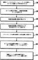
第3図は、本発明の好適な実施例による第2図のワイヤレス・ナビゲーション・システム200の動作を示すフローチャートである。論理フローはステップ310から開始し、ここで遠隔ユニット213は基地局201から経路計画を要求し、現在位置および目的地を基地局201に与える。次に、ステップ320において、基地局201は遠隔ユニット213の要求を受信し、位置および目的地データを経路計画装置207に与える。ステップ330において、経路計画装置207は、ステップ340において、経路に関する中間地点および形状地点(基準点)を算出し、この情報を絶対座標の形式で基地局201に与える。経路情報が基地局201に与えられると、トランスレータ203は各絶対座標から基準地理的位置を減算することにより、各基準点を絶対座標から相対座標に変換する(ステップ350)。ステップ360において、基地局201は、各基準点の相対座標からなるメッセージを遠隔ユニット213に送信する。本発明の好適な実施例では、基準点情報からなるメッセージは、基地局201を識別する16ビットのヘッダとともに遠隔ユニット213に発信される。特に、メッセージは、TIA/EIA/IS−95Aのセクション7.7.2.3.2.1「システム・パラメータ・メッセージ」に記載されるようにBASE_IDフィールドを利用して発信される。基地局識別は、遠隔ユニット213が2つ以上の基地局と通信中である(ソフト・ハンドオフ)場合を考慮に入れるために遠隔ユニット213に供給される。遠隔ユニット313に基地局識別を供給することにより、遠隔ユニット213は、基準点の絶対座標を算出する際に、どの基地局の基準地理的位置を利用すべきかを判定できる。最後に、ステップ370において、遠隔ユニット213は基準地理的位置を利用して、各基準点の絶対座標を算出し、この情報を遠隔ユニット213に結合されたナビゲーション・システムに渡す。
第4図は、従来の方法を介して送信されるメッセージと、本発明の好適な実施例に従って送信されるメッセージとを示す。特に、第4図は、街路名(street name)(35ビット),デリミタ(7ビット)および3つの基準点の送信を示す。従来の送信方法(メッセージ401によって表される)は、街路名(この場合、“Maple”)およびデリミタを表す42ビットと、それに続く地理情報(遠隔ユニット213が動作を行う必要のある緯度/経度座標)の120ビットとからなる162ビットの基準点401を送信する。特に、各文字およびデリミタは、7ビットで表され、各緯度/経度基準点は40ビットで表される。明白なように、本発明の好適な実施例は、162ビット長のメッセージを、わずか89ビット長のメッセージと置きかえる。これをメッセージ403について示し、ここで従来の120ビット長の絶対緯度/経度データは、56ビット長の相対緯度/経度データに置きかえられる。
第5図は、本発明の好適な実施例による第2図のトランスレータ203を示す。トランスレータ203は、トランシーバ505,論理ユニット507および基準地理的位置格納装置503を含む。本発明の好適な実施例によるトランスレータ203の動作は、第6図に示すように行われる。ステップ601において、遠隔ユニット213は、点Aから点Bに移動したい旨を(アップリンク通信信号216を介して)基地局201に通知する。次に、ステップ603において、論理ユニット507はこの要求を(トランシーバ505を介して)受信し、また陸線205を利用して、この要求を経路計画装置207に通知する。ステップ605において、経路計画装置207は、マップ・データベース103および経路プラナ105を利用して、点Aから点Bの経路を算出し、この経路に関する情報を論理ユニット507に与える。本発明の好適な実施例では、経路計画装置207は、各基準点の絶対座標を識別する一連の44ビット基準点109をトランスレータ203に与える。ステップ607において、論理ユニット507は、一連の基準点109を受信し、また基準地理的位置格納装置503を利用して、各基準点から基準地理的位置を減算し、各基準点の一連の相対座標を生成する。次に、ステップ608において、トランシーバ505は各基準点の相対座標をダウンリンク通信信号218を介して遠隔ユニット213に送信する。
第7図は、本発明の好適な実施例による第2図の遠隔ユニット113を示す。遠隔ユニット113は、トランシーバ701,論理ユニット703および基準位置テーブル707からなる。図示のように、ナビゲーション装置705は、遠隔ユニット113に適切に結合される。遠隔ユニット113の動作は、第8図に示すように行われる。ステップ804において、論理ユニット703は、通信中の現在アクティブな基地局を解析し、各基地局の基準地理的位置および基地識別を判定する。上記のように、この情報は、遠隔ユニット213に送信される各基地局のシステム・パラメータ・メッセージ(System Parameter Message)から判定される。次に、ステップ803において、論理ユニット703は基準位置テーブル707にアクセスし、各基地局の基準地理的位置とともに、各基地局に関する識別情報を格納する。ステップ805において、遠隔ユニット213は経路計画情報を要求し、ステップ807において、遠隔ユニットは、経路を計算するために必要な各基準点の相対座標からなるメッセージを受信する。上記のように、本発明の好適な実施例では、このメッセージは、各基準点の相対座標を生成する際に用いられる基準地理的位置を有する基地局を識別する16ビット・ヘッダを収容する。
続いて、ステップ809において、論理ユニット703は基準位置テーブル707にアクセスして、16ビット・ヘッダで識別された基地局が基準位置テーブル707にあるかどうかを判定する。このステップは、遠隔ユニット213が基地局とソフト・ハンドオフを行うが、この特定の基地局の基準地理的位置をまだ取得していない場合に必要となる。ステップ809において、16ビット・ヘッダで識別された基地局が基準位置テーブル707にあると判定された場合、論理フローはステップ815に進む。ステップ809において、16ビット・ヘッダで識別された基地局が基準位置テーブル707にないと判定された場合、タイマが設定され(ステップ811)、ステップ817において、論理ユニット703は通信中の現在アクティブな基地局を解析し、各基地局の基準地理的位置および基地識別を判定する。次に、ステップ818において、論理ユニット703は基準位置テーブル707にアクセスし、各基地局の基準地理的位置とともに、各基準局に関する識別情報を格納する。ステップ813において、論理ユニット703は、タイマ709が終了したかどうかを判定し、終了していなければ、論理フローはステップ817に戻る。ステップ813において、タイマ709が終了したと判定された場合、論理フローはステップ821に進み、ここで16ビット・ヘッダで識別される基地局が基準位置テーブル707にあるかどうか再度判定され、もしなければ、論理フローはステップ823に進み、ここでエラー・メッセージが遠隔ユニット213で表示される。ステップ821において、16ビット・ヘッダで識別された基地局が基準位置テーブル707にあると判定された場合、論理フローはステップ815に進む。ステップ815において、論理ユニット703は、16ビット・ヘッダで識別された基地局に対応する基準地理的位置を取り出し、この基準地理的位置を各基準点の相対座標に加算することにより、各基準点の絶対座標を算出する。各基準点の絶対座標はナビゲーション装置に送信され(ステップ819)、論理フローはステップ825において終了する。
例
以下の例は、本発明の実施例を説明するものであり、本発明の範囲を制限するものではない。第9図は、経路計画装置によって計画される経路の一例を示す。この例では、ユーザは始点901から終点915に移動することを希望する。第9図から明らかなように、始点901は緯度40°00’30”,経度85°02’30”に位置し、また終点915は緯度40°03’15”,経度85°00’28”に位置する。始点901と終点915との間の経路は、3つの中間地点(901,907,909)と、5つの形状地点(903,905,911,913,915)とを含む。さらに、基地局201は、緯度40°00’10”,経度85°00’20”の基準地理的位置を送信する。以下の表1は、第9図に示す経路の絶対座標および相対座標(秒単位)を示す。

Kensington/+144030+306150+144150+306150+144190+306143Elm/+144205+306115Maple/+144205+306080+144210+306058+144210+306047+144195+306028。各数値は20ビットで表され、各文字は7ビットで表され、またデリミタは7ビットで表されるので、上記のメッセージは全部で197ビットで送信される。送信する前に各基準点から基準地理的位置を減算することにより、本発明の好適な実施例による経路計画メッセージの送信は、次のように131ビット(各数値は9ビットで表される)で送信できる:
Kensington/+20+130+140+130+180+123Elm/+195+95Maple/+195+60+200+38+200+27+185+8。明白なように、各基準点の相対座標のみを遠隔ユニット213に放送することにより、従来の方法に比べて短い長さのメッセージで基準点を遠隔ユニット213に送信できる。
上記の発明,具体的な詳細および図面の説明は、本発明の範囲を制限することを意図するものではない。例えば、基地局201から遠隔ユニット213に相対座標を送信する以外に、位置情報を基地局201に供給する際に、相対座標を遠隔ユニット213から基地局201に送信できる。本発明の意図は、発明の精神および範囲から逸脱せずに、さまざまな修正を本発明に対して行うことが可能なことであり、このような一切の修正は請求の範囲内であるものとする。The present invention relates generally to reducing message length within a communication system, and more particularly to reducing message length within wireless navigation and information systems.
BACKGROUND OF THE INVENTION A typical navigation system presents a user with point-to-point guidance given a starting point and an ending point. For example, a user unfamiliar with a specific area needs to move from point A to point B. Given a start point (point A) and an end point (point B), a typical navigation system calculates the best route between the start point and end point and presents this route to the user. Wireless navigation systems are particularly useful in that they allow users real-time access to the navigation system on the way. This enables continuous route planning without having to plan an itinerary in advance.
FIG. 1 shows a conventional wireless navigation system 100. The navigation system 100 includes, for example, NAMPS (Narrowband Advanced Mobile Phone Service) protocol, AMPS (Advanced Mobile Phone Service) protocol, CDMA (Code Division Multiple Access) protocol, PDC (Personal Digital Cellular) protocol, GSM (Global System for Mobile). Analog or digital wireless navigation systems that use system protocols such as, but not limited to, Communications (Communications) protocol, Two-Way Paging protocol or United States Digital Cellular (USDC) protocol It may be a system. The navigation system 100 includes a base station (BTS) 101 having a
In operation,
Since a typical path may include hundreds of
[Brief description of the drawings]
FIG. 1 shows a conventional wireless navigation system.
FIG. 2 shows a wireless navigation system according to a preferred embodiment of the present invention.
FIG. 3 is a flowchart illustrating the operation of the wireless navigation system of FIG. 2 according to a preferred embodiment of the present invention.
FIG. 4 shows a message sent via a conventional method and a message sent according to a preferred embodiment of the present invention.
FIG. 5 shows the translator of FIG. 2 according to a preferred embodiment of the present invention.
FIG. 6 is a flowchart illustrating the operation of the translator of FIG. 2 according to a preferred embodiment of the present invention.
FIG. 7 shows the remote unit of FIG. 2 according to a preferred embodiment of the present invention.
FIG. 8 is a flowchart illustrating the operation of the remote unit of FIG. 2 in accordance with a preferred embodiment of the present invention.
FIG. 9 shows an example of a route that can be planned by the route planning device.
Detailed Description of the Drawings Generally speaking, latitude and longitude information within a wireless navigation and information system is transmitted from a route planning device to a base station. The translator converts each reference point from absolute coordinates to relative coordinates by subtracting a constant value from each absolute coordinate. In the preferred embodiment of the present invention, the reference geographic location is subtracted from each absolute coordinate. The base station then sends a message consisting of the relative coordinates of each reference point to the remote unit. Finally, the remote unit uses this reference geographic location to calculate the absolute coordinates of each reference point and passes this information to a navigation device coupled to the remote unit. By broadcasting only the relative coordinates of each reference point to the remote unit, the reference point can be transmitted to the remote unit with a message having a shorter length than the conventional method.
The present invention provides a method for shortening the message length, comprising the step of determining the absolute coordinates of the reference point and the step of determining the latitude and longitude. Next, the relative coordinates of the reference point are determined based on the absolute coordinates of the reference point and the latitude and longitude. Finally, the relative coordinates of the reference point are transmitted. By transmitting only the relative coordinates of each reference point to the remote unit, the reference point can be transmitted to the remote unit with a message having a shorter length compared to the conventional method.
Another embodiment of the present invention provides a method for reducing message length in a communication system that includes determining a latitude and longitude of a reference point and determining a reference geographic location of a base station. Next, the base geographic location of the base station is subtracted from the latitude and longitude of the base point to become the relative coordinates of the base point. Finally, the relative coordinates of the reference point are transmitted. By transmitting only the relative coordinates of each reference point to the remote unit, the reference point can be transmitted to the remote unit with a message having a shorter length compared to the conventional method.
Another embodiment of the present invention provides a navigation device for determining the latitude and longitude of a reference point, the latitude and longitude of the base station, and the latitude and route of the reference point and the latitude and route of the base station. The apparatus comprises a logic unit for determining relative coordinates and a transceiver for transmitting a message composed of relative coordinates of a reference point.
Before describing the preferred embodiment, the following definitions provide the necessary background terms.
Reference Point: The geographical location (way point or shape point) where the remote unit needs to perform some action (ie, turn left, turn right, etc.) is there).
Absolute Coordinate: Latitude and longitude coordinates that define a geographic location from an absolute point of view.
Relative Coordinate: Latitude and longitude coordinates obtained by subtracting the reference geographic location from absolute coordinates.
Reference Geographic Location: A constant value used to obtain relative coordinates. In the preferred embodiment of the present invention, a fixed geographic location is used as the reference geographic location.
FIG. 2 illustrates a
The
As described in Section 7.7.2.3.2.1 “System Parameters Message” of TIA / EIA / IS-95A, the
FIG. 3 is a flowchart illustrating the operation of the
FIG. 4 shows a message sent via a conventional method and a message sent according to a preferred embodiment of the present invention. In particular, FIG. 4 shows the transmission of a street name (35 bits), a delimiter (7 bits) and three reference points. The traditional transmission method (represented by message 401) consists of a street name (in this case “Maple”) and 42 bits representing a delimiter followed by geographic information (latitude / longitude that the
FIG. 5 shows the
FIG. 7 shows the
Subsequently, in
Examples The following examples illustrate embodiments of the invention and do not limit the scope of the invention. FIG. 9 shows an example of a route planned by the route planning apparatus. In this example, the user wishes to move from the
Kensington / + 144030 + 306150 + 144150 + 306150 + 144190 + 306143Elm / + 144205 + 306115Maple / + 144205 + 306080 + 144210 + 306058 + 144210 + 306047 + 144195 + 306028. Since each numerical value is represented by 20 bits, each character is represented by 7 bits, and the delimiter is represented by 7 bits, the above message is transmitted in 197 bits in total. By subtracting the reference geographic location from each reference point before transmission, the transmission of the route planning message according to the preferred embodiment of the present invention is 131 bits (each number is represented by 9 bits) as follows: You can send with:
Kensington / + 20 + 130 + 140 + 130 + 180 + 123 Elm / + 195 + 95 Maple / + 195 + 60 + 200 + 38 + 200 + 27 + 185 + 8. Obviously, by broadcasting only the relative coordinates of each reference point to the
The above invention, specific details and description of the drawings are not intended to limit the scope of the invention. For example, in addition to transmitting relative coordinates from the
Claims (4)
経路の計算に必要な各基準点の相対座標と、各基準点の相対座標の生成に基地局の基準地理的位置が利用された基地局の基地局識別情報とを、遠隔ユニットによって受信する段階と、
前記遠隔ユニットが基地局の基準地理的位置を格納しているか否かを、前記遠隔ユニットによって判定する段階と、
前記遠隔ユニットによって、前記基地局の基準地理的位置が格納されていないと判定された時、遠隔ユニットが通信している一連の基地局の内の少なくとも一つの基地局から、その基地局の基準地理的位置を遠隔ユニットによって受信及び格納する段階と、
受信した各基準点の緯度及び経度を生成するため、受信した各基準点の相対座標に対して、基地局の基準地理的位置を加算する段階と
からなる、通信システム内でメッセージ長を短縮するための方法。 In a method for reducing message length in a communication system,
Receiving, by the remote unit, the relative coordinates of each reference point required for route calculation and the base station identification information of the base station where the base geographic location of the base station was used to generate the relative coordinates of each reference point When,
Determining by the remote unit whether the remote unit stores a reference geographical location of a base station;
When the remote unit determines that the base geographic reference location of the base station is not stored, the reference of the base station from at least one base station in the series of base stations with which the remote unit is communicating. Receiving and storing a geographical location by a remote unit;
Adding the base geographic location of the base station to the relative coordinates of each received reference point to generate the latitude and longitude of each received reference point;
A method for reducing message length in a communication system.
前記トランシーバを介して、経路の計算に必要な各基準点の相対座標と、基地局の基準地理的位置が各基準点の相対座標の生成に利用された基地局の基地局識別情報とを、遠隔ユニットによって受信し、
前記基地局の基準地理的位置が基準位置テーブルに格納されているか否かを判定し、
前記基地局の基準地理的位置が格納されていないと判定された時、遠隔ユニットが通信している一連の基地局の内の少なくとも一つの基地局から、トランシーバを介して、その基地局の基準地理的位置を受信し、かつ、前記基準位置テーブルに格納し、
遠隔ユニットに通信可能に結合されたナビゲーション装置のために、受信した各基準点の緯度及び経度を生成するため、受信した各基準点の相対座標に対して、基地局の基準地理的位置を加算するようにした遠隔ユニット。 In a remote unit comprising a transceiver, a reference position table, and a logic unit coupled to the transceiver and the reference position table,
Via the transceiver, the relative coordinates of each reference point required for route calculation, and the base station identification information of the base station in which the reference geographic position of the base station was used to generate the relative coordinates of each reference point , Received by the remote unit,
Determining whether the reference geographical location of the base station is stored in a reference location table;
When it is determined that the reference geographical location of the base station is not stored, the reference of the base station is received via a transceiver from at least one base station in a series of base stations with which the remote unit is communicating. Receiving a geographical location and storing it in the reference location table;
For the navigation device communicatively coupled to the remote unit, add the base geographic location of the base station to the relative coordinates of each received reference point to generate the latitude and longitude of each received reference point Remote unit designed to do this.
Applications Claiming Priority (3)
| Application Number | Priority Date | Filing Date | Title |
|---|---|---|---|
| US08/731,108 | 1996-10-09 | ||
| US08/731,108 US5745867A (en) | 1996-10-09 | 1996-10-09 | Method and apparatus for reducing message length within a communication system |
| PCT/US1997/014389 WO1998015911A1 (en) | 1996-10-09 | 1997-08-13 | Method and apparatus for reducing message length within a communication system |
Publications (2)
| Publication Number | Publication Date |
|---|---|
| JP2001501737A JP2001501737A (en) | 2001-02-06 |
| JP3814302B2 true JP3814302B2 (en) | 2006-08-30 |
Family
ID=24938098
Family Applications (1)
| Application Number | Title | Priority Date | Filing Date |
|---|---|---|---|
| JP51749498A Expired - Fee Related JP3814302B2 (en) | 1996-10-09 | 1997-08-13 | Method and remote unit for reducing message length in a communication system |
Country Status (6)
| Country | Link |
|---|---|
| US (1) | US5745867A (en) |
| EP (1) | EP1004081A4 (en) |
| JP (1) | JP3814302B2 (en) |
| KR (1) | KR100323566B1 (en) |
| BR (1) | BR9711893A (en) |
| WO (1) | WO1998015911A1 (en) |
Families Citing this family (23)
| Publication number | Priority date | Publication date | Assignee | Title |
|---|---|---|---|---|
| US5987381A (en) * | 1997-03-11 | 1999-11-16 | Visteon Technologies, Llc | Automobile navigation system using remote download of data |
| KR100366716B1 (en) * | 1998-10-13 | 2003-01-06 | 가부시키가이샤 자나비 인포메틱스 | Broadcasting type information providing system and travel environment information collecting device |
| US6292743B1 (en) | 1999-01-06 | 2001-09-18 | Infogation Corporation | Mobile navigation system |
| EP1224645B2 (en) | 1999-09-07 | 2010-02-17 | Robert Bosch Gmbh | Method for coding and decoding objects in a road traffic network |
| US7783508B2 (en) | 1999-09-20 | 2010-08-24 | Numerex Corp. | Method and system for refining vending operations based on wireless data |
| US6718177B1 (en) * | 1999-09-20 | 2004-04-06 | Cellemetry, Llc | System for communicating messages via a forward overhead control channel for a programmable logic control device |
| US6856808B1 (en) * | 1999-10-29 | 2005-02-15 | Cellmetry, Llc | Interconnect system and method for multiple protocol short message services |
| JP3494143B2 (en) * | 1999-11-18 | 2004-02-03 | トヨタ自動車株式会社 | Route guidance information providing system and route guidance information providing method |
| DE60128365T2 (en) | 2000-08-15 | 2008-01-17 | Lcc International, Inc. | METHOD AND ARRANGEMENTS FOR DETERMINING THE SIGNAL COVER |
| US7245928B2 (en) * | 2000-10-27 | 2007-07-17 | Cellemetry, Llc | Method and system for improved short message services |
| DE10055195A1 (en) * | 2000-11-07 | 2002-05-08 | Bosch Gmbh Robert | Producing appendices for positive geographical referencing of object involves producing tree of potential paths starting from object, assessing paths using criteria, encoding remaining paths |
| US6980905B2 (en) * | 2001-04-12 | 2005-12-27 | Elead Electronics Co., Ltd. | Remote-end route-calculating navigation system |
| US20030081735A1 (en) * | 2001-08-27 | 2003-05-01 | Emory Thomas M. | System and method for detecting and reporting defective telephone lines and alarm events |
| US6718237B1 (en) * | 2002-03-28 | 2004-04-06 | Numerex Investment Corp. | Method for reducing capacity demands for conveying geographic location information over capacity constrained wireless systems |
| KR100543308B1 (en) * | 2003-05-23 | 2006-01-20 | 주식회사 팬택앤큐리텔 | Method for supplying the infomation of location in GPS server or GPS wireless communication terminal |
| US7323970B1 (en) | 2004-01-21 | 2008-01-29 | Numerex Corporation | Method and system for remote interaction with a vehicle via wireless communication |
| US20070129063A1 (en) * | 2005-12-01 | 2007-06-07 | Recio Renato J | Digital information retrieval for wireless phones |
| WO2007136723A2 (en) | 2006-05-17 | 2007-11-29 | Numerex Corp. | System and method for prolonging wireless data product's life |
| MX2009008343A (en) | 2007-02-06 | 2009-10-30 | Numerex Corp | Service escrowed transportable wireless event reporting system. |
| JP2011170627A (en) * | 2010-02-18 | 2011-09-01 | Sumitomo Electric Ind Ltd | Traffic information communication system, mobile terminal device, information processor, generating method and processing method of uplink information, map data structure, data structure of uplink information |
| US9311067B2 (en) * | 2011-08-04 | 2016-04-12 | Robert W. Connors | Content changeable smart phone application for navigable venues and multi-party navigational system |
| CN103106281A (en) * | 2013-02-22 | 2013-05-15 | 上海埃威航空电子有限公司 | Electronic chart position point data simplification method and system |
| EP3240311B1 (en) | 2015-01-16 | 2021-03-03 | Huawei Technologies Co., Ltd. | Location information acquiring methods and devices |
Family Cites Families (5)
| Publication number | Priority date | Publication date | Assignee | Title |
|---|---|---|---|---|
| US4954958A (en) * | 1988-08-19 | 1990-09-04 | Hacowie Corporation | Directional information system |
| US5067081A (en) * | 1989-08-30 | 1991-11-19 | Person Carl E | Portable electronic navigation aid |
| US5172321A (en) * | 1990-12-10 | 1992-12-15 | Motorola, Inc. | Vehicle route planning system |
| JP3227272B2 (en) * | 1993-05-28 | 2001-11-12 | アイシン・エィ・ダブリュ株式会社 | Navigation device |
| JP3203979B2 (en) * | 1994-10-06 | 2001-09-04 | トヨタ自動車株式会社 | Vehicle data processing system, vehicle data processing device, and vehicle data processing method |
-
1996
- 1996-10-09 US US08/731,108 patent/US5745867A/en not_active Expired - Lifetime
-
1997
- 1997-08-13 WO PCT/US1997/014389 patent/WO1998015911A1/en active IP Right Grant
- 1997-08-13 BR BR9711893A patent/BR9711893A/en not_active Application Discontinuation
- 1997-08-13 KR KR1019997003108A patent/KR100323566B1/en not_active IP Right Cessation
- 1997-08-13 EP EP97938338A patent/EP1004081A4/en not_active Withdrawn
- 1997-08-13 JP JP51749498A patent/JP3814302B2/en not_active Expired - Fee Related
Also Published As
| Publication number | Publication date |
|---|---|
| WO1998015911A1 (en) | 1998-04-16 |
| JP2001501737A (en) | 2001-02-06 |
| US5745867A (en) | 1998-04-28 |
| EP1004081A1 (en) | 2000-05-31 |
| KR20000049039A (en) | 2000-07-25 |
| EP1004081A4 (en) | 2000-05-31 |
| KR100323566B1 (en) | 2002-02-19 |
| BR9711893A (en) | 1999-08-24 |
Similar Documents
| Publication | Publication Date | Title |
|---|---|---|
| JP3814302B2 (en) | Method and remote unit for reducing message length in a communication system | |
| US6898521B2 (en) | Navigation device | |
| CN101228457B (en) | Satellite positioning system receivers and methods | |
| CN100507444C (en) | Navigation tags | |
| US7480513B2 (en) | Location based service system and position information updating method thereof | |
| EP1118837A2 (en) | Method and system of providing navigation services to portable communication devices | |
| US6028553A (en) | Method for dynamic route recommendation | |
| KR20150096653A (en) | Method of calculating route, and method or device for obtaining route | |
| CN101625245A (en) | Navigation terminal and navigation method | |
| JP2003511773A (en) | Downloading geographical data to a mobile station and displaying a map | |
| JP2003516057A (en) | Telecommunications system | |
| AU2001285754A1 (en) | Method and mobile station for route guidance | |
| JP2006010441A (en) | Mobile communication terminal and map display system | |
| EP1280030A1 (en) | Method and system for converting positioning signals of different coordinate systems to prescribed coordinate systems | |
| KR100647742B1 (en) | System and method for navigation service based on traffic | |
| KR100802090B1 (en) | Method and apparatus for providing 3-dimension location based service | |
| US6681179B1 (en) | Method for remote routes calculation and navigation with automatic route detection and revision | |
| JP2007232686A (en) | Traffic guide device, system, and method, mobile terminal equipment, display method, and program | |
| KR20030037175A (en) | Urgency rescue service method of position base | |
| CN114459462A (en) | Electronic map switching method, electronic map processing method, electronic map switching terminal, electronic map server and storage medium | |
| KR20020079106A (en) | navigation system guiding shot-way and shot-time course for target point | |
| JP2005212499A (en) | Train route guide method and train route guide system | |
| KR100695077B1 (en) | Navigation System and Method for Guidance of POI | |
| US8060496B2 (en) | Method for creating appendices that clearly reference the location of an object | |
| JP7397108B2 (en) | Receiving device and location identification method |
Legal Events
| Date | Code | Title | Description |
|---|---|---|---|
| A621 | Written request for application examination |
Free format text: JAPANESE INTERMEDIATE CODE: A621 Effective date: 20040802 |
|
| RD02 | Notification of acceptance of power of attorney |
Free format text: JAPANESE INTERMEDIATE CODE: A7422 Effective date: 20040802 |
|
| A131 | Notification of reasons for refusal |
Free format text: JAPANESE INTERMEDIATE CODE: A131 Effective date: 20050906 |
|
| A601 | Written request for extension of time |
Free format text: JAPANESE INTERMEDIATE CODE: A601 Effective date: 20051206 |
|
| A602 | Written permission of extension of time |
Free format text: JAPANESE INTERMEDIATE CODE: A602 Effective date: 20060130 |
|
| A521 | Request for written amendment filed |
Free format text: JAPANESE INTERMEDIATE CODE: A523 Effective date: 20060306 |
|
| TRDD | Decision of grant or rejection written | ||
| A01 | Written decision to grant a patent or to grant a registration (utility model) |
Free format text: JAPANESE INTERMEDIATE CODE: A01 Effective date: 20060509 |
|
| A61 | First payment of annual fees (during grant procedure) |
Free format text: JAPANESE INTERMEDIATE CODE: A61 Effective date: 20060605 |
|
| R150 | Certificate of patent or registration of utility model |
Free format text: JAPANESE INTERMEDIATE CODE: R150 |
|
| LAPS | Cancellation because of no payment of annual fees |