JP3813552B2 - Work stress determination device, work stress determination program, and work stress determination method - Google Patents
Work stress determination device, work stress determination program, and work stress determination method Download PDFInfo
- Publication number
- JP3813552B2 JP3813552B2 JP2002212683A JP2002212683A JP3813552B2 JP 3813552 B2 JP3813552 B2 JP 3813552B2 JP 2002212683 A JP2002212683 A JP 2002212683A JP 2002212683 A JP2002212683 A JP 2002212683A JP 3813552 B2 JP3813552 B2 JP 3813552B2
- Authority
- JP
- Japan
- Prior art keywords
- stress
- work
- subject
- masseter
- during
- Prior art date
- Legal status (The legal status is an assumption and is not a legal conclusion. Google has not performed a legal analysis and makes no representation as to the accuracy of the status listed.)
- Expired - Fee Related
Links
Images


Classifications
-
- A—HUMAN NECESSITIES
- A61—MEDICAL OR VETERINARY SCIENCE; HYGIENE
- A61B—DIAGNOSIS; SURGERY; IDENTIFICATION
- A61B5/00—Measuring for diagnostic purposes; Identification of persons
- A61B5/68—Arrangements of detecting, measuring or recording means, e.g. sensors, in relation to patient
- A61B5/6801—Arrangements of detecting, measuring or recording means, e.g. sensors, in relation to patient specially adapted to be attached to or worn on the body surface
- A61B5/6813—Specially adapted to be attached to a specific body part
- A61B5/6814—Head
-
- A—HUMAN NECESSITIES
- A61—MEDICAL OR VETERINARY SCIENCE; HYGIENE
- A61B—DIAGNOSIS; SURGERY; IDENTIFICATION
- A61B5/00—Measuring for diagnostic purposes; Identification of persons
- A61B5/16—Devices for psychotechnics; Testing reaction times ; Devices for evaluating the psychological state
- A61B5/165—Evaluating the state of mind, e.g. depression, anxiety
-
- A—HUMAN NECESSITIES
- A61—MEDICAL OR VETERINARY SCIENCE; HYGIENE
- A61B—DIAGNOSIS; SURGERY; IDENTIFICATION
- A61B5/00—Measuring for diagnostic purposes; Identification of persons
- A61B5/16—Devices for psychotechnics; Testing reaction times ; Devices for evaluating the psychological state
- A61B5/18—Devices for psychotechnics; Testing reaction times ; Devices for evaluating the psychological state for vehicle drivers or machine operators
-
- A—HUMAN NECESSITIES
- A61—MEDICAL OR VETERINARY SCIENCE; HYGIENE
- A61B—DIAGNOSIS; SURGERY; IDENTIFICATION
- A61B5/00—Measuring for diagnostic purposes; Identification of persons
- A61B5/24—Detecting, measuring or recording bioelectric or biomagnetic signals of the body or parts thereof
- A61B5/316—Modalities, i.e. specific diagnostic methods
- A61B5/389—Electromyography [EMG]
-
- A—HUMAN NECESSITIES
- A61—MEDICAL OR VETERINARY SCIENCE; HYGIENE
- A61B—DIAGNOSIS; SURGERY; IDENTIFICATION
- A61B5/00—Measuring for diagnostic purposes; Identification of persons
- A61B5/22—Ergometry; Measuring muscular strength or the force of a muscular blow
- A61B5/224—Measuring muscular strength
- A61B5/228—Measuring muscular strength of masticatory organs, e.g. detecting dental force
-
- A—HUMAN NECESSITIES
- A61—MEDICAL OR VETERINARY SCIENCE; HYGIENE
- A61B—DIAGNOSIS; SURGERY; IDENTIFICATION
- A61B5/00—Measuring for diagnostic purposes; Identification of persons
- A61B5/45—For evaluating or diagnosing the musculoskeletal system or teeth
- A61B5/4528—Joints
Landscapes
- Health & Medical Sciences (AREA)
- Life Sciences & Earth Sciences (AREA)
- Engineering & Computer Science (AREA)
- General Health & Medical Sciences (AREA)
- Veterinary Medicine (AREA)
- Biophysics (AREA)
- Biomedical Technology (AREA)
- Heart & Thoracic Surgery (AREA)
- Medical Informatics (AREA)
- Molecular Biology (AREA)
- Surgery (AREA)
- Animal Behavior & Ethology (AREA)
- Physics & Mathematics (AREA)
- Public Health (AREA)
- Pathology (AREA)
- Psychiatry (AREA)
- Child & Adolescent Psychology (AREA)
- Developmental Disabilities (AREA)
- Educational Technology (AREA)
- Hospice & Palliative Care (AREA)
- Psychology (AREA)
- Social Psychology (AREA)
- Measurement Of The Respiration, Hearing Ability, Form, And Blood Characteristics Of Living Organisms (AREA)
- Measurement And Recording Of Electrical Phenomena And Electrical Characteristics Of The Living Body (AREA)
Description
【0001】
【発明の属する技術分野】
本発明は、作業中ストレス判定装置、作業中ストレス判定プログラム及び作業中ストレス判定方法に関し、特に、作業中の動作によって被験者が受けるストレスを判定するのに有用である。
【0002】
【従来の技術】
一般に、心的な負担(ストレス)の測定方法としては、心電図、脳波などの生体情報を用いる方法がある。この種の生体情報を用いる方法は、被験者の統制を必要とする場合が多く、解析の都合上ある程度の時間を必要とするため、安静時のストレスの判定に用いられている。
【0003】
ところで、人は、自動車などの運転時(作業時)には大きなストレスを受けることが多い。そのストレスは、人によって受ける場面も大きさも異なる。例えば、自動車の乗り心地や操縦性などが悪いと、力みを生じやすい。このような力みは、円滑な運転を妨げ事故の原因にもなる。
【0004】
そのため、自動車などの開発・設計では、腕や足といった運転中に負荷が大きい箇所の筋肉の活動を示す筋電信号によって、生体情報の中でも計測が簡便で即応性の優れた筋電図を得て、運転中の被験者の人体にかかる負担を直接的に判定している。
【0005】
【発明が解決しようとする課題】
一般に、人がストレスを受けた精神的負担の状態では、不随意な過剰な筋肉の活動である「力み」が現れる。そのため、ストレスは、その筋肉の活動状態を測定することによって判定することが可能である。
【0006】
しかし、従来の場合では、運転等の作業自体に大きくかかわる腕や足などの筋肉の活動を筋電図で得て、作業中の筋肉の運動を測定して人体の負担を判定していたけれども、筋電図を基に作業中の心的な負担(ストレス)を客観的に表す方法は知られていなかった。
【0007】
また、腕や足などの作業中の筋肉の活動の筋電図では、自動車の運転などの作業による筋肉の活動の筋電信号とストレスによる筋肉の「力み」の筋電信号とが重畳されて得られるため、自動車の運転などの作業による筋肉の活動かストレスによる筋肉の活動かを判別することができなかった。
【0008】
また、筋電図以外の生体情報を用いる方法では、被験者に統制が必要な場合が多く、解析の都合上ある程度の記録時間が必要であるため、作業中のストレスを正しく再現・評価することが困難であった。
【0009】
また、従来の自動車などの開発・設計では、乗り心地や操縦性といった心的な負担(ストレス)に関わる項目は被験者が感じた状態を主観的に言葉で表していたに過ぎず、客観的にストレスを判定することができなかった。
【0010】
そこで、本発明は、上記に鑑みてなされたものであって、被験者の顎の開閉を行う咬筋にストレスによって生じる「力み」を定量的に測定して、自動車の運転などの作業中のストレスを客観的に判定することができるストレス判定装置、作業中ストレス判定プログラム及び作業中ストレス判定方法を提供することを目的とする。
【0011】
【課題を解決するための手段】
上述の目的を達成するために、本発明による作業中ストレス判定装置は、被験者の顎の開閉を行う咬筋の活動と独立した筋肉の活動によって行う対象作業中に咬筋の筋電信号を入力する筋電信号入力手段と、対象作業が被験者のストレッサーとして働いた場合に現れる咬筋の活動の変化を示す筋電信号からストレスを判定するストレス判定手段とを有することを特徴とする。
【0012】
この構成によれば、被験者が作業中に受けるストレスを作業中筋電信号の変化から認識して作業中のストレスを判定できるため、例えば、被験者がドライバーとして操舵中(作業中)、自動車の乗り心地や操縦性といった精神的負担となって現れる項目を定量的に表し、客観的に操舵中(作業中)のストレスを判定することができるようになる。
【0013】
被験者にストレスが掛かると、筋肉に「力み」が生じる。このときの「力み」の度合いを測定すれば、ストレスを判定することができる。しかし、作業中には種々の筋肉も作業に伴って活動しているため、「力み」を正確に測定するためには、作業中は主に使用しないと思われる筋肉の活動を測定すればよいことが推察される。特に、顎はストレスが生じると噛締めによって強い力が掛かるため、主に腕や足といった部位の筋肉を使用する作業の場合には、被験者の顎の咬筋の活動を計測することによって、その活動の強度や時間変化を把握することによってストレスを判定することができる。
【0014】
なお、対象作業は、積極的に顎を使う作業を除く意味であり、例えば、手を使う作業、足を使う作業、指を使う作業、腰を使う作業、背中を使う作業である。具体的な被験者は、例えば、自動車、自動二輪車、船舶、航空機などの運転者、工場などのプラントオペレーターや、OA(オフィスオートメーション)オペレーターや、事務員などである。また、被験者の顎の開閉を行う咬筋の活動と独立した筋肉の活動とは、積極的に発話や欠伸や咀嚼といった顎を使った動作を除く意味である。また、ストレッサーとは、ストレスの原因となる刺激である。
【0015】
つぎの発明による作業中ストレス判定装置は、前記ストレス判定手段は、被験者が前記対象作業と独立して咬筋を用いた所望の作業を行う期間をストレスの判定の対象期間から除外することを特徴とする。
【0016】
この構成によれば、被験者が対象作業中に対象作業と独立して咬筋を用いた所望の作業を行った場合でも、対象作業と独立して咬筋を用いた所望の作業による筋肉の活動の変化があるときには、そのときの筋電信号をストレスの判定には使用しないで、対象作業と独立して咬筋を用いた所望の作業中と判断するようにしたため、ストレスの判定を正確に行うことができるようになる。
【0017】
例えば、自動車の運転中に、被験者の咬筋の筋電図を得てストレスを判定する場合に、被験者が咬筋を使用して喋るという動作を行ったときには、喋るという行為によって咬筋が活動しているため、ストレスによる「力み」とは別に筋電図に表れてしまう。このようなときに、喋るという動作中は、対象作業と独立して咬筋を用いた所望の作業中と判断してストレスの判定に使用しないこととすることによって、ストレスを正確に判定することができるようになる。
【0018】
つぎの発明による作業中ストレス判定装置は、前記ストレス判定手段は、被験者の発話を入力した音声データ又は被験者の顔面の画像を入力した画像データから、被験者が前記対象作業と独立して咬筋を用いた所望の作業を行っている期間を特定する。
【0019】
この構成によれば、被験者が前記対象作業と独立して咬筋を用いた所望の作業を行う期間を特定できる。
【0020】
なお、本発明による作業中ストレス判定装置では、前記対象作業を被験者の行う車両の操舵とするのが好ましい。
【0021】
また、ストレス判定には、例えば、一定時間での平均自乗根(RMS)や積分値(IEMG(Integrated Electromyogram ))が用いられる。このようなRMSやIEMGは、筋電信号パラメータ算出手段によって算出させればよい。この筋電信号パラメータ算出手段は、RMSやIEMGを算出する関数を定義しておき、入力される筋電信号に対して時系列に従って算出処理を行えばよい。
【0022】
また、本発明では、後述の実施例で示すように、例えば、RMSに基づく信号強度をストレス判定に用いてもよい。この信号強度は、例えば、所定動作を行った時間毎に算出される。例えば、複数の区間を走行している場合には、その区間毎に強度を算出し、各区間毎の傾向を見ることが可能になる。なお、この筋電信号の強度は、強度算出手段が算出すればよい。
【0023】
なお、前記対象作業と独立して咬筋を用いた所望の作業認識手段は、対象作業中に被験者が行った対象作業と独立して咬筋を用いた所望の作業である咀嚼や発話といった咬筋の主たる機能の動作を認識するのが好ましい。この場合には、前記ストレス判定手段は、前記作業中筋電信号の変化を咀嚼や発話といった対象作業と独立して咬筋を用いた所望の作業中と判定すればよい。
【0024】
また、上述の目的を達成するために、本発明の作業中判定プログラムは、作業中ストレス判定装置の各手段を、コンピューターが実行するプログラムモジュールとして含むことを特徴とする。
【0025】
なお、各手段を構成するプログラムは、モジュール単位に分割されたものだけでなく、各モジュールの各ステップを含む1つのプログラムであってもよく、本発明はこの場合も含む。各手段を実現する各ステップは、1つのプログラムに組み込まれたとしても、ステップ毎に組み込まれるため、実質的にモジュール化しているからである。
【0026】
さらに、上述の目的を達成するために、本発明による作業中ストレス判定方法は、被験者の顎の開閉を行う咬筋の活動と独立した筋肉の活動によって行う対象作業中に咬筋の筋電信号を入力する筋電信号入力ステップと、対象作業が被験者のストレッサーとして働いた場合に現れる咬筋の活動の変化を示す筋電信号からストレスを判定するストレス判定ステップとを含むことを特徴とする。
【0027】
この構成によれば、被験者が作業中に受けるストレスを作業中筋電信号の変化から認識して作業中のストレスを判定できるため、例えば、自動車の乗り心地や操縦性といった精神的負担となって現れる項目を定量的に表し、客観的に作業中のストレスを判定することができるようになる。
【0028】
【発明の実施の形態】
以下、本発明につき図面を参照しつつ詳細に説明する。なお、この実施形態により本発明が限定されるものではない。また、以下の説明では、腕や足などの筋肉を使用して行う自動車の運転などの作業中の場合を説明する。
【0029】
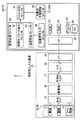
図1は、本発明の実施形態の作業中ストレス判定装置の構成を説明するブロック図である。図2は、本発明の実施形態の作業中ストレスを検知する筋電信号を入力する電極の取付例を示す図である。
【0030】
図1において、この作業中ストレス判定システム1は、咬筋の活動電位を入力する咬筋電位入力装置10と、前記咬筋電位入力装置10が入力した筋電信号に基づいてストレスを判定するパーソナルコンピューター(PC)20とで構成されている。
【0031】
前記咬筋電位入力装置10は、センサー11によって咬筋の活動電位を検知する。このセンサー11は、約5mm程度離して配置する電極12,13と、基準電位をとるアース電極14とで構成する。図2に示すように、顔面Fの咬筋X(破線)の上部の皮膚に電極12,13を貼付するとともに、耳たぶにアース電極14を貼付する。
【0032】
ここで、咬筋は、顔の側面にある大きな筋で、側頭筋と共に咀嚼筋と呼ばれ顎の閉じ動作、例えば、咀嚼や発話を行う動作に作用する。そのため、咬筋は、腕や足などの筋肉を使用して行う自動車の運転などの作業中では、通常、活動しない。ところが、被験者にストレスが生じて全身に力が入ってしまう場合には、咬筋にも「力み」が生じる。本実施形態では、そのストレスが生じているときの咬筋の筋電信号を計測するようにしたものである。
【0033】
また、図1に戻って、この咬筋電位入力装置10は、前記センサー11からの筋電信号を増幅する生体アンプ15と、交流波形の筋電信号を直流波形の筋電信号に整流する整流器16と、筋電信号中の雑音を除去する平滑化フィルタ17と、アナログ信号としての筋電信号をディジタル信号に変換するA/Dコンバータ18と、前記PC20側とのデータのやり取りを制御するインターフェース(I/F)19とを有している。
【0034】
この咬筋電位入力装置10では、被験者が自動車を運転中(作業中)に、右旋回や左旋回などによってストレスを受けて、被験者の全身に力が入って咬筋に「力み」が生じると、そのときの「力み」による咬筋電信号のアナログ波形からなる筋電信号は、電極12,13から入力され、生体アンプ15で増幅されて整流器16によって整流され、さらに、平滑化フィルタ17によって雑音を除去されてA/Dコンバータ18によってディジタル信号に変換され、I/F19によってPC20側に転送される。
【0035】
一方、前記PC20は、前記咬筋電位入力装置10から転送される筋電信号を基に作業中のストレスを判定する作業中ストレス判定装置であり、各種プログラムモジュールを適宜呼び出して全体の処理を司るCPU21と、前記咬筋電位入力装置10との間のデータのやり取りを制御するインターフェース(I/F)22と、前記CPU21の実行する各種プログラムや各種データを格納するROM23、RAM24と、ストレス判定結果などを表示するディスプレイ25と、前記咬筋電位入力装置10から転送されてくる筋電信号や各種プログラムや各種データを格納するハードディスク(HD)26とを主に有している。なお、CPU21とI/F22とROM23とRAM24とディスプレイ25とHD26とはバスによってそれぞれ接続されている。
【0036】
また、前記CPU21は、特に、被験者の顎の開閉を行う咬筋の活動と独立した筋肉の活動によって行う対象作業中に咬筋の筋電信号を入力する筋電信号入力モジュール30と、ストレス判定の指標としてのパラメータに筋電信号を加工する信号処理モジュール31(例えば、一定時間での平均自乗根(RMS)や積分値(IEMG(Integrated Electromyogram )の関数に基づく筋電信号パラメータを算出する筋電信号パラメータ算出モジュール32又は筋電信号の強度によるパラメータを算出する強度算出モジュール33)と、対象作業中に被験者が行った対象作業と独立して咬筋を用いた所望の作業を認識する対象外作業認識モジュール34と、対象作業が被験者のストレッサーとして働いた場合に現れる筋肉の活動の変化を作業中筋電信号の変化から認識してストレスを判定するストレス判定モジュール35とを呼び出してストレス判定処理を実行する。
【0037】
これら各モジュールは、ROM23、RAM24、HD26のいずれの記憶媒体に記憶させておいてもよい。また、それぞれのモジュールをばらばらに記憶させてもよい。さらに、図示しないCD−ROMその他の記憶媒体に記憶させておいてもよい。
【0038】
前記筋電信号入力モジュール30は、被験者の顎の開閉を行う咬筋の活動と独立した筋肉の活動によって行う対象作業中に咬筋の作業中筋電信号を入力する手段である。例えば、この筋電信号入力モジュール30は、ストレス判定作業を自動車の運転とした場合に、被験者が自動車の運転中(作業中)の咬筋の筋電信号を入力する。特に、被験者がストレスを感じているときには、咬筋の「力み」として現れる。この「力み」時の筋電信号は、被験者がストレスを感じていない「力み」の無い時の筋電信号に比べて高い電位となる。
【0039】
なお、この筋電信号入力モジュール30は、咬筋電位入力装置10からリアルタイムに転送されてくる筋電信号を入力するばかりでなく、咬筋電位入力装置10から転送された筋電信号をHD26に蓄積しておき、そのHD26から読み出すようにしてもよい。
【0040】
前記信号処理モジュール31は、ストレス判定モジュール35が判定する指標としてのパラメータに加工する手段である。この信号処理モジュール31は、例えば、RMSやIEMGを算出する関数を定義しておき、入力される筋電信号に対して時系列に従って算出処理を行う筋電信号パラメータ算出モジュール32や筋電信号の強度によるパラメータとする強度算出モジュール33によって構成される。
【0041】
前記筋電信号パラメータ算出モジュール32は、例えば、咬筋電位入力装置10側から転送されてくる咬筋の筋電信号の変化の微分値を取り、急峻な変化を生じたときには、動作によってストレスを生じたことを示すため、その値をストレス判定モジュール35に渡す。
【0042】
また、前記強度算出モジュール33は、例えば、所定動作毎の筋電信号の強度のピーク値や平均値などの値を取り、所定動作毎の筋電信号の強度同士の比較を行い、その結果をストレス判定モジュール35に渡す。なお、強度の判定は、予め計測された最大筋電位によって正規化されたIEMGやRMSを用い、予め用意された閾値によって行ってもよい。
【0043】
前記対象外作業認識モジュール34は、対象作業中に被験者が行った対象作業と独立して咬筋を用いた所望の作業を認識して、その結果を前記ストレス判定モジュール35に渡す手段である。また、この対象外作業認識モジュール34は、対象作業中に被験者が行った対象作業と独立して咬筋を用いた所望の作業である咀嚼や発話といった咬筋の主たる機能の動作を認識して、その結果を前記ストレス判定モジュール35に渡す手段としても機能するようにしてある。
【0044】
また、前記対象外作業認識モジュール34は、対象作業中の対象作業と独立して咬筋を用いた所望の作業を撮影した動画像データから対象作業と独立して咬筋を用いた所望の作業動作を認識して、その結果を前記ストレス判定モジュール35に渡す手段としても機能するようにしてもよい。この場合には、図示しないカメラを被験者に向けて設置しておき、そのカメラの映像をPC20側に取り込む必要がある。そして、この場合には、前記ストレス判定モジュール35は、咀嚼又は発話のいずれでも対象作業と独立して咬筋を用いた所望の作業と認識できる。
【0045】
また、前記対象外作業認識モジュール34は、発話を録音した音声データから発話を対象作業と独立して咬筋を用いた所望の作業動作と認識して、前記ストレス判定モジュール35に渡すようにしてもよい。この場合には、図示しないマイクロフォンを被験者近傍に設置しておき、そのマイクロフォンからの音声をPC20側に取り込む必要がある。そして、この場合には、前記ストレス判定モジュール35は発話中と認識することになる。
【0046】
前記ストレス判定モジュール35は、対象作業が被験者のストレッサーとして働いた場合に現れる筋肉の活動の変化を作業中筋電信号の変化から認識してストレスを判定する手段である。
【0047】
この場合には、このストレス判定モジュール35は、被験者が作業中に受けるストレスを筋電信号入力モジュール30によって作業中筋電信号の変化から認識して作業中のストレスをストレス判定モジュール35によって判定できるため、例えば、自動車の乗り心地や操縦性といった精神的負担となって現れる項目を定量的に表し、客観的に作業中のストレスを判定できる。
【0048】
このストレス判定モジュール35は、前記筋電信号から認識する筋電信号の大小、前記筋電信号の強度から認識する強弱の少なくとも1つで判定する手段でもある。
【0049】
例えば、前記筋電信号パラメータ算出モジュール32が、咬筋電位入力装置10側から転送されてくる咬筋の筋電信号の変化の微分値を取り、急峻な変化を生じたときに、その値をストレス判定モジュール35に渡した場合には、このストレス判定モジュール35は、その筋電信号ではストレスが生じていると判断する。
【0050】
また、例えば、前記強度算出モジュール33が、所定動作毎の筋電信号の強度のピーク値や平均値などの値を取り、所定動作毎の筋電信号の強度同士の比較を行い、その結果をストレス判定モジュール35に渡した場合には、このストレス判定モジュール35では、その比較結果によってばらつきや強度を判断して、ストレスが発生している動作を特定する。
【0051】
したがって、このストレス判定モジュール35は、作業前後の筋電信号が小さく、作業中の筋電信号が大きければ、作業中にストレスを受けていると判定することができ、また、作業前後の筋電信号が弱く、作業中の筋電信号が強ければ、作業中にストレスを受けていると判定することができる。また、ストレスは、筋肉の「力み」による筋電信号の大小又は筋電信号の強弱として定量的に表すことができる。
【0052】
また、このストレス判定モジュール35は、前記対象作業と独立して咬筋を用いた所望の作業が前記作業中筋電信号を入力している筋肉を使った動作の場合には前記作業中筋電信号の変化を対象作業と独立して咬筋を用いた所望の作業中と判定する手段としても機能する。例えば、このストレス判定モジュール35は、前記対象外作業認識モジュール34が対象作業と独立して咬筋を用いた所望の作業を咀嚼や発話といった咬筋の主たる機能の動作と認識した場合に、前記作業中筋電信号の変化を咀嚼や発話といった対象作業と独立して咬筋を用いた所望の作業中と判定する。
【0053】
この場合には、このストレス判定モジュール35は、被験者が対象作業中に対象作業と独立して咬筋を用いた所望の作業を行った場合でも、対象作業と独立して咬筋を用いた所望の作業による筋肉の活動の変化があるときには、対象外作業認識モジュール34が対象作業と独立して咬筋を用いた所望の作業であることを認識して、ストレス判定モジュール35がそのときの作業中筋電信号をストレスの判定には使用しないで、対象作業と独立して咬筋を用いた所望の作業中と判断する。そのため、このストレス判定モジュール35は、対象作業と独立して咬筋を用いた所望の作業による筋電変化を選別し、ストレスの判定を正確に行える。
【0054】
例えば、自動車の運転中に、被験者の咬筋の筋電図を得てストレスを判定する場合に、被験者が発話したときには、このストレス判定モジュール35が、被験者の咬筋の活動を発話によるものとして対象作業と独立して咬筋を用いた所望の作業中と判断し、ストレスの判定には用いないこととすることによって、ストレスを正確に判定できる。
【0055】
それでは、上述した作業中ストレス判定システム1の判定処理をPC20側の動作を主にして説明する。なお、上述したように、電極12, 13及びアース電極14は、被験者の咬筋の上部及び耳たぶの皮膚に貼付しておく。この状態で、電極12, 13からは咬筋の筋電信号が、生体アンプ15、整流器16、平滑化フィルタ17、A/Dコンバータ18及びI/F19を介してPC20側に伝送されているものとする。
【0056】
図3に、本発明の実施形態の作業中ストレス判定処理を説明するフローチャートを示す。CPU21では、筋電信号入力モジュール30は、筋電信号を入力して、信号処理モジュール31に筋電信号を渡す(S1)。信号処理モジュールでは、筋電信号パラメータ算出モジュール32が、上述したように、例えば、咬筋電位入力装置10側から転送されてくる咬筋の筋電信号の変化の微分値を取り、急峻な変化を生じたときには、動作によってストレスを生じたことを示すため、その値をストレス判定モジュール35に渡す(S2)。また、強度算出モジュール33では、上述したように、例えば、所定動作毎の筋電信号の強度のピーク値や平均値などの値を取り、所定動作毎の筋電信号の強度同士の比較を行い、その結果をストレス判定モジュール35に渡す(S3)。ここで、対象外作業認識モジュール34が、対象作業と独立して咬筋を用いた所望の作業の有無を判断し、対象作業中に被験者が行った対象作業と独立して咬筋を用いた所望の作業を認識して、その結果を前記ストレス判定モジュール35に渡す(S4)。
【0057】
すると、ストレス判定モジュール35では、対象作業が被験者のストレッサーとして働いた場合に現れる筋肉の活動の変化を作業中筋電信号の変化から認識してストレスを判定する(S5)。例えば、前記筋電信号パラメータ算出モジュール32が、咬筋電位入力装置10側から転送されてくる咬筋の筋電信号の変化の微分値を取り、急峻な変化を生じたときに、その値をストレス判定モジュール35に渡した場合には、このストレス判定モジュール35は、その筋電信号ではストレスが生じていると判断する。また、例えば、前記強度算出モジュール33が、所定動作毎の筋電信号の強度のピーク値や平均値などの値を取り、所定動作毎の筋電信号の強度同士の比較を行い、その結果をストレス判定モジュール35に渡した場合には、このストレス判定モジュール35では、その比較結果によってばらつきや強度を判断して、ストレスが発生している動作を特定する。なお、このストレス判定モジュール35は、上記S4で対象作業と独立して咬筋を用いた所望の作業が認識された場合には、対象作業と独立して咬筋を用いた所望の作業中と判定する。
【0058】
上記実施形態によれば、自動車の運転などの作業中のストレスを判定するために、力みとなって現れる筋肉の活動としてストレスを感知して、客観的に作業中のストレスを判定することができるようになる。特に、上記実施形態によれば、咬筋の筋電信号を測定して、その測定結果を基に、噛締めによる「力み」からストレスを判定することができる。また、上記実施形態によれば、筋電図を用いて判定するようにしたため、脳波や心電図など他の生体情報を用いる場合に比べ、被験者への統制が少なく、非常に短時間の計測結果からも被験者の心理状態を把握することができるため、より精度の高い評価ができるようになる。
【0059】
したがって、上記実施形態によれば、被験者が作業中に受けるストレスを作業中の筋電信号の変化から認識して作業中のストレスを判定できるようになる。そのため、例えば、被験者がドライバーとして操舵中(作業中)、自動車の乗り心地や操縦性といった精神的負担となって現れる項目を定量的に表し、客観的に操舵中(作業中)のストレスを判定することができるようになる。
【0060】
なお、上記実施形態では、咬筋の活動を計測の対象とした場合を説明したが、作業中に主に活動する筋肉とは別の筋肉であれば、咬筋に限らない。例えば、発話中のストレスを判定する場合には、発話とは直接関係しない腕や足の筋肉の活動電位を計測するようにしてもよい。
【0061】
また、上記実施形態では、ストレス判定手段などの各手段は、プログラムを構成するモジュールとし、CPUが実行するものとして説明したが、これに限らず、LSIチップなどに電子回路として構成するようにしてもよい。
【0062】
また、上記実施形態では、前記咬筋電位入力装置10には整流器16を設け、直流成分として扱う場合を説明したが、交流成分のまま扱うようにしてもよい。この場合は、生体アンプ15と平滑化フィルタ17とを直接接続する。
【0063】
【実施例】
以下に、上記実施形態のストレス判定処理によって得られるストレス評価例を示す。なお、ここでは、作業として車両の操舵の場合を示す。また、複数の作業は、異なる走行条件下での作業を表す。
【0064】
図4は、筋電信号―時間を示すグラフである。この例では、異なる条件下で単位時間毎の筋電信号を得た。グラフには筋電信号の変化が波形に現れている。波形A,B,C,D,Eは、それぞれ異なる条件下での作業A,B,C,D,E時の筋電信号を示す。中でも、波形Eは、急峻な変化を持っている。この急峻な変化は、前記筋電信号パラメータ算出モジュール32によって判別できる。この波形Eのように急峻な変化が、ストレスの発現を示し、ストレス判定モジュール35がストレスと判定する。
【0065】
図5は、筋電信号強度―作業を示すグラフである。A,B,C,D,Eは、図4で表した各作業を示す。筋電信号強度は、ここではRMSを用いている。このグラフでは、作業Eが、他の作業に比べて高い強度を持っている。このようなグラフで表される関係では、前記強度算出モジュール33が、作業毎のRMSを算出し、ストレス判定モジュール35が、各値を比較して作業Eの場合に大きなストレスが被験者に掛かっていると判定する。
【0066】
次に、比較例として被験者の官能値判断のサンプルを示す。
図6は、筋電信号―官能値(力み)を示す散布図である。○は作業A、×は作業B、□は作業C、△は作業D、▽は作業Eを示す。なお、この散布図は、5人の被験者のサンプルである。また、力みがない場合には、正で表す。中でも、▽の作業Eでは、全ての人が力みを生じていると回答した。このことは、図4及び5で示した作業Eが大きなストレスが掛かるという結果と一致する。
【0067】
図7は、筋電信号―官能値(反応)を示す散布図である。○は作業A、×は作業B、□は作業C、△は作業D、▽は作業Eを示す。ここでは、各作業は、所定条件を与えた場合である。なお、この散布図は、5人の被験者のサンプルである。また、車両の反応が良い場合には、正で表す。中でも、▽の作業Eでは、全ての人が車両の反応が悪いと回答している。このことは、車両の反応が悪い場合には、図4及び5で表した大きなストレスを感じていることを示している。
【0068】
【発明の効果】
以上説明したように、本発明によれば、被験者が作業中に受けるストレスを作業中の筋電信号の変化から認識して作業中のストレスを判定できる効果を奏する。そのため、本発明によれば、例えば、被験者がドライバーとして操舵中(作業中)、自動車の乗り心地や操縦性といった精神的負担となって現れる項目を定量的に表し、客観的に操舵中(作業中)のストレスを判定できる効果を奏する。
【図面の簡単な説明】
【図1】 本発明の実施形態の作業中ストレス判定装置の構成を説明するブロック図である。
【図2】 図2は、本発明の実施形態の作業中ストレスを検知する筋電信号を入力する電極の取付例を示す図である。
【図3】 本発明の実施形態の作業中ストレス判定処理を説明するフローチャートである。
【図4】 筋電信号―時間を示すグラフである。
【図5】 筋電信号強度―作業を示すグラフである。
【図6】 筋電信号―官能値(力み)を示す散布図である。
【図7】 筋電信号―官能値(反応)を示す散布図である。
【符号の説明】
1 作業中ストレス判定システム
10 咬筋電位入力装置
11 センサー
12,13 電極
14 アース電極
15 生体アンプ
16 整流器
17 平滑化フィルタ
18 コンバータ
19 I/F
20 PC
21 CPU
22 I/F
23 ROM
24 RAM
25 ディスプレイ
26 HD
30 筋電信号入力モジュール
31 信号処理モジュール
32 筋電信号パラメータ算出モジュール
33 強度算出モジュール
34 対象外作業認識モジュール
35 ストレス判定モジュール[0001]
BACKGROUND OF THE INVENTION
The present invention relates to an in-work stress determination device, an in-work stress determination program, and an in-work stress determination method, and is particularly useful for determining the stress experienced by a subject by an operation during work.
[0002]
[Prior art]
In general, as a method for measuring a mental burden (stress), there is a method using biological information such as an electrocardiogram and an electroencephalogram. This type of biometric information method often requires subject control and requires a certain amount of time for convenience of analysis, and is therefore used to determine stress at rest.
[0003]
By the way, people often receive great stress when driving a car or the like (during work). The stress varies from person to person depending on the scene. For example, if the ride comfort and controllability of an automobile are poor, it is easy to generate power. Such a force prevents smooth driving and causes an accident.
[0004]
For this reason, in the development and design of automobiles and the like, electromyograms indicating the activity of muscles in places with heavy loads during driving, such as arms and legs, provide electromyograms that are easy to measure and have excellent responsiveness in biological information. Thus, the burden on the human body of the driving subject is directly determined.
[0005]
[Problems to be solved by the invention]
In general, in a mentally stressed state in which a person is stressed, “strength” that is involuntary excessive muscle activity appears. Therefore, stress can be determined by measuring the activity state of the muscle.
[0006]
However, in the conventional case, the activity of muscles such as arms and legs, which are greatly involved in the operation itself such as driving, is obtained with an electromyogram, and the load of the human body is determined by measuring the movement of the muscle during the work. There has been no known method for objectively expressing the mental burden (stress) during work based on an electromyogram.
[0007]
Also, in the electromyogram of muscle activity during work such as arms and legs, the EMG signal of muscle activity due to work such as driving a car and the EMG signal of muscle "strengthening" due to stress are superimposed. Therefore, it was impossible to determine whether the muscle activity was due to work such as driving a car or the muscle activity due to stress.
[0008]
In addition, methods using biological information other than electromyograms often require control of the subject, and a certain amount of recording time is required for the convenience of analysis, so it is possible to correctly reproduce and evaluate stress during work. It was difficult.
[0009]
In addition, in the development and design of conventional automobiles, items related to the mental burden (stress) such as ride comfort and maneuverability are merely a subjective representation of the state felt by the subject, and objectively Stress could not be determined.
[0010]
Therefore, the present invention has been made in view of the above, and quantitatively measures the “force” caused by stress on the masseter muscle that opens and closes the subject's jaw, thereby stress during operation such as driving a car. It is an object of the present invention to provide a stress determination device, a stress determination program during work, and a stress determination method during work.
[0011]
[Means for Solving the Problems]
In order to achieve the above-described object, the stress determination device during operation according to the present invention is a muscle that inputs a myoelectric signal of the masseter during the target operation performed by the activity of the muscle independent of the activity of the masseter that opens and closes the jaw of the subject. It is characterized by having an electric signal input means and a stress determination means for judging stress from a myoelectric signal indicating a change in masseter muscle activity that appears when the target work works as a stressor for the subject.
[0012]
According to this configuration, since the stress that the test subject receives during the work can be recognized from the change in the electromyogram signal during the work, the stress during the work can be determined. This makes it possible to quantitatively represent items that appear as mental burdens such as maneuverability and maneuverability, and to objectively determine the stress during steering (working).
[0013]
When the subject is stressed, “strength” is generated in the muscles. By measuring the degree of “force” at this time, the stress can be determined. However, since various muscles are also active during work, in order to accurately measure “strength”, it is necessary to measure the activities of muscles that are not expected to be used during work. It is inferred that it is good. In particular, when the stress is applied to the jaw, a strong force is applied by tightening. Therefore, when working mainly on muscles such as arms and legs, the activity is measured by measuring the activity of the subject's jaw masseter. It is possible to determine the stress by grasping the intensity and time change.
[0014]
Note that the target work means a work other than the work that actively uses the jaw, for example, a work that uses hands, a work that uses legs, a work that uses fingers, a work that uses the waist, and a work that uses the back. Specific subjects are, for example, drivers of automobiles, motorcycles, ships, airplanes, plant operators such as factories, OA (office automation) operators, and office workers. In addition, the activity of the masseter that is independent of the masseter muscle that opens and closes the subject's jaw means that the movement using the jaw such as speech, extension, and mastication is actively excluded. A stressor is a stimulus that causes stress.
[0015]
The stress determination device during work according to the next invention is characterized in that the stress determination means excludes a period during which the subject performs a desired work using the masseter muscle independently of the target work from the target period of the stress determination. To do.
[0016]
According to this configuration, even when the subject performs a desired work using the masseter muscle independently of the target work during the target work, a change in muscle activity due to the desired work using the masseter muscle independently of the target work When there is, the myoelectric signal at that time is not used for stress determination, but it is determined that the desired work using the masseter muscle is being performed independently of the target work, so that the stress can be accurately determined. become able to.
[0017]
For example, when driving a car and determining stress by obtaining an electromyogram of the subject's masseter muscle, when the subject performs an action of scolding using the masseter muscle, the masseter muscle is active by the act of scolding Therefore, it appears on the electromyogram separately from the "force" due to stress. In such a case, it is possible to accurately determine the stress by determining that the desired operation using the masseter muscle is being performed independently of the target operation and not using it for the determination of the stress during the operation of scolding. become able to.
[0018]
In the work stress determination device according to the next invention, the stress determination means uses the masseter muscle independently of the target work from the voice data input from the subject or the image data input from the face image of the subject. The period during which the desired work has been performed is specified.
[0019]
According to this configuration, it is possible to specify a period during which the subject performs a desired work using the masseter muscle independently of the target work.
[0020]
In the apparatus for determining stress during work according to the present invention, the target work is preferably steering of a vehicle performed by a subject.
[0021]
Also, stress judgment In For example, the mean square root (RMS) and integral value (IEMG (Integrated Electromyogram)) in a certain time Used . like this RMS and IEMG May be calculated by the myoelectric signal parameter calculating means. This myoelectric signal parameter calculating means may define a function for calculating RMS or IEMG, and perform calculation processing on the input myoelectric signal in time series.
[0022]
Moreover, in this invention, as shown in the below-mentioned Example, you may use the signal strength based on RMS for stress determination, for example. This signal strength is For example, every time a predetermined operation is performed Calculation Out Is done. For example, when traveling in a plurality of sections, it is possible to calculate the strength for each section and see the tendency for each section. The strength of the myoelectric signal may be calculated by the strength calculating means.
[0023]
Note that the desired work recognition means using the masseter independent of the target work is the main masseter muscle such as mastication and speech that is the desired work using the masseter independent of the target work performed by the subject during the target work. It is preferable to recognize the operation of the function. In this case, the stress determination means may determine that the change in the myoelectric signal during work is during a desired work using the masseter, independently of the target work such as mastication or speech.
[0024]
In order to achieve the above-described object, the in-work determination program of the present invention includes each means of the in-work stress determination device as a program module executed by a computer.
[0025]
In addition, the program which comprises each means may be one program containing each step of not only the program divided | segmented into the module unit, but this invention also includes this case. This is because each step for realizing each means is substantially modularized because it is incorporated for each step even if it is incorporated in one program.
[0026]
Further, in order to achieve the above-described object, the stress determination method during operation according to the present invention inputs a myoelectric signal of the masseter during the target operation performed by the activity of the muscle independent of the activity of the masseter that opens and closes the jaw of the subject. And a stress determination step of determining stress from a myoelectric signal indicating a change in the activity of the masseter muscle that appears when the target work works as a stressor for the subject.
[0027]
According to this configuration, it is possible to determine the stress during the work by recognizing the stress that the subject receives during the work from the change in the electromyogram signal during the work. Items can be expressed quantitatively, and stress during work can be determined objectively.
[0028]
DETAILED DESCRIPTION OF THE INVENTION
Hereinafter, the present invention will be described in detail with reference to the drawings. In addition, this invention is not limited by this embodiment. Further, in the following description, a case will be described in which work such as driving a car is performed using muscles such as arms and legs.
[0029]
FIG. 1 is a block diagram illustrating a configuration of a stress determination apparatus during work according to an embodiment of this invention. FIG. 2 is a diagram illustrating an example of attachment of electrodes for inputting a myoelectric signal for detecting stress during work according to the embodiment of the present invention.
[0030]
In FIG. 1, a
[0031]
The masseter muscle potential input device 10 detects the action potential of the masseter muscle using a
[0032]
Here, the masseter muscle is a large muscle on the side of the face and is called a masticatory muscle together with the temporal muscle, and acts on a jaw closing operation, for example, an operation of mastication or speech. For this reason, the masseter muscles are not normally active during operations such as driving a car using muscles such as arms and legs. However, when stress occurs in the subject and force is applied to the whole body, “force” is also generated in the masseter muscle. In this embodiment, the myoelectric signal of the masseter muscle when the stress is generated is measured.
[0033]
Returning to FIG. 1, the masseter potential input device 10 includes a
[0034]
In this masseter potential input device 10, when the subject is driving (working) the car and is stressed by turning right or turning left, force is applied to the whole body of the subject and “force” is generated in the masseter muscle. The myoelectric signal composed of an analog waveform of the masseter myoelectric signal by “force” at that time is input from the
[0035]
On the other hand, the
[0036]
Further, the
[0037]
These modules may be stored in any storage medium such as the
[0038]
The myoelectric
[0039]
The myoelectric
[0040]
The signal processing module 31 is means for processing a parameter as an index determined by the
[0041]
The myoelectric signal
[0042]
The
[0043]
The non-target
[0044]
The non-target
[0045]
Further, the non-target
[0046]
The
[0047]
In this case, the
[0048]
The
[0049]
For example, when the myoelectric signal
[0050]
Further, for example, the
[0051]
Therefore, if the myoelectric signal before and after the work is small and the myoelectric signal during the work is large, the
[0052]
In addition, the
[0053]
In this case, the
[0054]
For example, when an electromyogram of the subject's masseter muscle is obtained during driving of the subject to determine the stress, when the subject speaks, the
[0055]
The determination process of the above-described
[0056]
FIG. 3 shows a flowchart for explaining the stress determination process during work according to the embodiment of the present invention. In the
[0057]
Then, the
[0058]
According to the embodiment, in order to determine the stress during work such as driving a car, the stress is sensed as muscle activity that appears as a force, and the stress during work can be objectively determined. become able to. In particular, according to the above-described embodiment, it is possible to measure a myoelectric signal of the masseter muscle and determine the stress from the “force” due to the tightening based on the measurement result. Further, according to the above embodiment, since the determination is made using the electromyogram, compared to the case where other biological information such as an electroencephalogram or an electrocardiogram is used, there is less control over the subject, and the measurement result is very short. Since it is possible to grasp the psychological state of the subject, more accurate evaluation can be performed.
[0059]
Therefore, according to the above embodiment, it is possible to determine the stress during work by recognizing the stress that the subject receives during work from the change in the myoelectric signal during work. Therefore, for example, when the subject is steering as a driver (working), the items that appear as mental burdens such as the ride comfort and maneuverability of the car are quantitatively expressed, and the stress during steering (working) is objectively determined. Will be able to.
[0060]
In the above embodiment, the case where the activity of the masseter muscle is the object of measurement has been described. However, the muscle is not limited to the masseter muscle as long as it is a muscle different from the muscle that is mainly active during work. For example, when determining the stress during utterance, the action potentials of the muscles of the arms and legs that are not directly related to the utterance may be measured.
[0061]
In the above embodiment, each means such as the stress determination means is described as a module constituting a program and executed by the CPU. However, the present invention is not limited to this, and is configured as an electronic circuit on an LSI chip or the like. Also good.
[0062]
In the above embodiment, the masseter potential input device 10 is provided with the
[0063]
【Example】
Below, the stress evaluation example obtained by the stress determination process of the said embodiment is shown. Here, the case of steering the vehicle is shown as the work. A plurality of operations represent operations under different traveling conditions.
[0064]
FIG. 4 is a graph showing myoelectric signal-time. In this example, the myoelectric signal for each unit time was obtained under different conditions. The graph shows changes in myoelectric signals in the waveform. Waveforms A, B, C, D, and E indicate myoelectric signals during operations A, B, C, D, and E under different conditions. Among these, the waveform E has a steep change. This steep change can be determined by the myoelectric signal
[0065]
FIG. 5 is a graph showing myoelectric signal intensity-operation. A, B, C, D, and E indicate the operations shown in FIG. Here, RMS is used as the myoelectric signal intensity. In this graph, operation E has higher strength than other operations. In the relationship represented by such a graph, the
[0066]
Next, a sample of sensory value judgment of a subject is shown as a comparative example.
FIG. 6 is a scatter diagram showing myoelectric signal-sensory value (force). ○ indicates operation A, × indicates operation B, □ indicates operation C, Δ indicates operation D, and ▽ indicates operation E. This scatter diagram is a sample of five subjects. Moreover, when there is no force, it represents with positive. Above all, in the work E of ▽, all the people answered that they were producing strength. This agrees with the result that the work E shown in FIGS.
[0067]
FIG. 7 is a scatter diagram showing myoelectric signal-sensory value (response). ○ indicates operation A, × indicates operation B, □ indicates operation C, Δ indicates operation D, and ▽ indicates operation E. Here, each operation is a case where a predetermined condition is given. This scatter diagram is a sample of five subjects. In addition, when the response of the vehicle is good, it is represented as positive. Among them, in the work E of ▽, all the people answered that the reaction of the vehicle is bad. This indicates that when the reaction of the vehicle is bad, the user feels the great stress shown in FIGS.
[0068]
【The invention's effect】
As described above, according to the present invention, it is possible to determine the stress during work by recognizing the stress that the subject receives during work from the change in the myoelectric signal during work. Therefore, according to the present invention, for example, an item appearing as a mental burden such as a ride comfort and a maneuverability of a vehicle is quantitatively represented while the subject is steering as a driver (working), and is being objectively steered (working) The effect of being able to determine the stress of (medium) is achieved.
[Brief description of the drawings]
FIG. 1 is a block diagram illustrating a configuration of a working stress determination device according to an embodiment of the present invention.
FIG. 2 is a diagram showing an example of attachment of electrodes for inputting a myoelectric signal for detecting stress during operation according to the embodiment of the present invention.
FIG. 3 is a flowchart illustrating a stress determination process during work according to the embodiment of this invention.
FIG. 4 is a graph showing myoelectric signal-time.
FIG. 5 is a graph showing myoelectric signal intensity-operation.
FIG. 6 is a scatter diagram showing myoelectric signals-sensory values (force).
FIG. 7 is a scatter diagram showing myoelectric signal-sensory value (response).
[Explanation of symbols]
1 Stress judgment system during work
10 Masseter muscle potential input device
11 Sensor
12,13 electrode
14 Ground electrode
15 Biological amplifier
16 Rectifier
17 Smoothing filter
18 Converter
19 I / F
20 PC
21 CPU
22 I / F
23 ROM
24 RAM
25 display
26 HD
30 Myoelectric signal input module
31 Signal processing module
32 EMG signal parameter calculation module
33 Strength calculation module
34 Unrecognized work recognition module
35 Stress judgment module
Claims (6)
Priority Applications (4)
| Application Number | Priority Date | Filing Date | Title |
|---|---|---|---|
| JP2002212683A JP3813552B2 (en) | 2002-07-22 | 2002-07-22 | Work stress determination device, work stress determination program, and work stress determination method |
| PCT/JP2003/009160 WO2004008958A1 (en) | 2002-07-22 | 2003-07-18 | Stress-at-work judging device, stress-at-work judging program, and stress-at-work judging method |
| EP03741484A EP1535571B1 (en) | 2002-07-22 | 2003-07-18 | Stress-at-work judging device, stress-at-work judging program, and stress-at-work judging method |
| US10/522,022 US7421293B2 (en) | 2002-07-22 | 2003-07-18 | Stress-at-work judging apparatus, stress-at-work judging program, and stress-at-work judging method |
Applications Claiming Priority (1)
| Application Number | Priority Date | Filing Date | Title |
|---|---|---|---|
| JP2002212683A JP3813552B2 (en) | 2002-07-22 | 2002-07-22 | Work stress determination device, work stress determination program, and work stress determination method |
Publications (3)
| Publication Number | Publication Date |
|---|---|
| JP2004049623A JP2004049623A (en) | 2004-02-19 |
| JP2004049623A5 JP2004049623A5 (en) | 2005-10-27 |
| JP3813552B2 true JP3813552B2 (en) | 2006-08-23 |
Family
ID=30767817
Family Applications (1)
| Application Number | Title | Priority Date | Filing Date |
|---|---|---|---|
| JP2002212683A Expired - Fee Related JP3813552B2 (en) | 2002-07-22 | 2002-07-22 | Work stress determination device, work stress determination program, and work stress determination method |
Country Status (4)
| Country | Link |
|---|---|
| US (1) | US7421293B2 (en) |
| EP (1) | EP1535571B1 (en) |
| JP (1) | JP3813552B2 (en) |
| WO (1) | WO2004008958A1 (en) |
Families Citing this family (20)
| Publication number | Priority date | Publication date | Assignee | Title |
|---|---|---|---|---|
| JP4433739B2 (en) | 2003-09-17 | 2010-03-17 | 横浜ゴム株式会社 | Work stress evaluation apparatus and work stress evaluation method |
| US20050130717A1 (en) * | 2003-11-25 | 2005-06-16 | Gosieski George J.Jr. | System and method for managing audio and visual data in a wireless communication system |
| US7231233B2 (en) * | 2003-11-25 | 2007-06-12 | G Squared, Llc | Combined multi-media and in ear monitoring system and method of remote monitoring and control thereof |
| JP4661115B2 (en) * | 2004-07-15 | 2011-03-30 | ソニー株式会社 | Signal processing apparatus, signal processing method, and mechanical apparatus |
| JP4857580B2 (en) * | 2005-03-29 | 2012-01-18 | 横浜ゴム株式会社 | Work characteristic evaluation apparatus, work characteristic evaluation method and program |
| US20070060830A1 (en) * | 2005-09-12 | 2007-03-15 | Le Tan Thi T | Method and system for detecting and classifying facial muscle movements |
| WO2007072412A2 (en) * | 2005-12-23 | 2007-06-28 | Koninklijke Philips Electronics N.V. | Stressor sensor and stress management system |
| US7313957B1 (en) | 2006-06-15 | 2008-01-01 | The Yokohama Rubber Co., Ltd. | Apparatus, method and program for evaluating work characteristic |
| EP1875860B1 (en) | 2006-07-05 | 2010-09-22 | The Yokohama Rubber Co., Ltd. | Apparatus, method and program for evaluating work characteristic |
| JP4957202B2 (en) * | 2006-11-17 | 2012-06-20 | 横浜ゴム株式会社 | Method for selecting highly sensitive skeletal muscle, device for selecting highly sensitive skeletal muscle, method for evaluating stress during work, and system for evaluating stress during work |
| US8117047B1 (en) | 2007-04-16 | 2012-02-14 | Insight Diagnostics Inc. | Healthcare provider organization |
| US8768489B2 (en) * | 2008-06-13 | 2014-07-01 | Gil Thieberger | Detecting and using heart rate training zone |
| CN101981533A (en) * | 2008-07-11 | 2011-02-23 | 松下电器产业株式会社 | An interface system utilizing the myoelectricity of masticatory muscles |
| US20120065480A1 (en) | 2009-03-18 | 2012-03-15 | Badilini Fabio F | Stress monitor system and method |
| JP5326739B2 (en) * | 2009-03-30 | 2013-10-30 | 横浜ゴム株式会社 | Vehicle roll feeling evaluation method and vehicle roll feeling evaluation device |
| RU2015148842A (en) * | 2013-06-14 | 2017-07-19 | Интерконтинентал Грейт Брендс Ллк | INTERACTIVE VIDEO GAMES |
| MX390354B (en) * | 2015-03-30 | 2025-03-20 | Centro De Investig Y De Estudios Avanzados Del I P N | DEVICE FOR SUPERFICIAL RECORDING OF MASSETER MUSCLES. |
| US20170186444A1 (en) * | 2015-12-24 | 2017-06-29 | Intel Corporation | Tracking user feeling about exercise |
| JP2019122655A (en) * | 2018-01-18 | 2019-07-25 | パシフィックメディコ株式会社 | Myoelectric potential acquisition apparatus |
| JP7296121B2 (en) * | 2019-12-27 | 2023-06-22 | 株式会社Agama-X | Information processing device and information processing program |
Family Cites Families (7)
| Publication number | Priority date | Publication date | Assignee | Title |
|---|---|---|---|---|
| US4344441A (en) * | 1980-07-03 | 1982-08-17 | Myo-Tronics Research, Inc. | Mandibular electromyograph |
| US4934378A (en) | 1989-03-31 | 1990-06-19 | Perry Jr John D | Bruxism method and apparatus using electrical signals |
| US5195531A (en) * | 1991-03-01 | 1993-03-23 | Bennett Henry L | Anesthesia adequacy monitor and method |
| US6233472B1 (en) * | 1995-06-06 | 2001-05-15 | Patient Comfort, L.L.C. | Electrode assembly and method for signaling a monitor |
| JP2002214083A (en) | 2001-01-17 | 2002-07-31 | Mazda Motor Corp | Vehicle stability evaluation apparatus, recording medium storing stability evaluation program, and stability evaluation method |
| JP2002230699A (en) * | 2001-01-31 | 2002-08-16 | Mazda Motor Corp | Driving load determination device, driving load determination method, computer program for executing the method, and storage medium storing the computer program |
| JP3912227B2 (en) | 2001-09-03 | 2007-05-09 | 株式会社豊田中央研究所 | Steering feeling measuring device |
-
2002
- 2002-07-22 JP JP2002212683A patent/JP3813552B2/en not_active Expired - Fee Related
-
2003
- 2003-07-18 US US10/522,022 patent/US7421293B2/en not_active Expired - Fee Related
- 2003-07-18 WO PCT/JP2003/009160 patent/WO2004008958A1/en not_active Ceased
- 2003-07-18 EP EP03741484A patent/EP1535571B1/en not_active Expired - Lifetime
Also Published As
| Publication number | Publication date |
|---|---|
| JP2004049623A (en) | 2004-02-19 |
| EP1535571A4 (en) | 2008-06-25 |
| WO2004008958A1 (en) | 2004-01-29 |
| US7421293B2 (en) | 2008-09-02 |
| EP1535571A1 (en) | 2005-06-01 |
| US20050245838A1 (en) | 2005-11-03 |
| EP1535571B1 (en) | 2012-08-29 |
Similar Documents
| Publication | Publication Date | Title |
|---|---|---|
| JP3813552B2 (en) | Work stress determination device, work stress determination program, and work stress determination method | |
| JP4433739B2 (en) | Work stress evaluation apparatus and work stress evaluation method | |
| CN102202569B (en) | Mobile body control device and mobile body control method | |
| US8200337B2 (en) | Method of selecting specific skeletal muscle highly sensitive to human psychological state, device for selecting specific skeletal muscle, method of evaluating stress during work, and system for evaluating stress during work | |
| US20070179396A1 (en) | Method and System for Detecting and Classifying Facial Muscle Movements | |
| EP1529487A1 (en) | Electrocardiogram analysis device and method thereof | |
| US20100179764A1 (en) | Method, apparatus, and program for evaluating drivability of a vehicle | |
| US20090177109A1 (en) | Methods and devices of multi-functional operating system for care-taking machine | |
| JP2010257343A (en) | Communication support device | |
| JPWO2009008261A1 (en) | Evaluation method of device operation force | |
| EP1535570B1 (en) | Device and method for assessing driver comfort | |
| Punsawad et al. | Weighted-frequency index for EEG-based mental fatigue alarm system | |
| KR20050063618A (en) | Method and appratus for recognizing positive/negative intention using fine change of gamma wave of brain wave | |
| JP4857580B2 (en) | Work characteristic evaluation apparatus, work characteristic evaluation method and program | |
| JP3161990B2 (en) | Robot control device | |
| JP4983892B2 (en) | Work stress evaluation apparatus and work stress evaluation method | |
| RU2378984C2 (en) | Device for control and evaluation of physiological processes | |
| JP3050624B2 (en) | Correlation data collection system | |
| JPH05212007A (en) | Electroencephalograph | |
| CN121393806A (en) | Brain-computer collaborative rehabilitation training control method, device, medium and terminal equipment | |
| EP1875860B1 (en) | Apparatus, method and program for evaluating work characteristic | |
| JP5964622B2 (en) | Stress evaluation device | |
| JPH09220208A (en) | Tension state estimation device with plural biological information selection function | |
| Wang et al. | Real-time control signal extraction based on instantaneous power of surface electromyogram |
Legal Events
| Date | Code | Title | Description |
|---|---|---|---|
| A521 | Request for written amendment filed |
Free format text: JAPANESE INTERMEDIATE CODE: A523 Effective date: 20050705 |
|
| A621 | Written request for application examination |
Free format text: JAPANESE INTERMEDIATE CODE: A621 Effective date: 20050705 |
|
| TRDD | Decision of grant or rejection written | ||
| A01 | Written decision to grant a patent or to grant a registration (utility model) |
Free format text: JAPANESE INTERMEDIATE CODE: A01 Effective date: 20060516 |
|
| A61 | First payment of annual fees (during grant procedure) |
Free format text: JAPANESE INTERMEDIATE CODE: A61 Effective date: 20060531 |
|
| R150 | Certificate of patent or registration of utility model |
Free format text: JAPANESE INTERMEDIATE CODE: R150 Ref document number: 3813552 Country of ref document: JP Free format text: JAPANESE INTERMEDIATE CODE: R150 |
|
| FPAY | Renewal fee payment (event date is renewal date of database) |
Free format text: PAYMENT UNTIL: 20090609 Year of fee payment: 3 |
|
| FPAY | Renewal fee payment (event date is renewal date of database) |
Free format text: PAYMENT UNTIL: 20100609 Year of fee payment: 4 |
|
| R250 | Receipt of annual fees |
Free format text: JAPANESE INTERMEDIATE CODE: R250 |
|
| FPAY | Renewal fee payment (event date is renewal date of database) |
Free format text: PAYMENT UNTIL: 20100609 Year of fee payment: 4 |
|
| FPAY | Renewal fee payment (event date is renewal date of database) |
Free format text: PAYMENT UNTIL: 20110609 Year of fee payment: 5 |
|
| R250 | Receipt of annual fees |
Free format text: JAPANESE INTERMEDIATE CODE: R250 |
|
| FPAY | Renewal fee payment (event date is renewal date of database) |
Free format text: PAYMENT UNTIL: 20110609 Year of fee payment: 5 |
|
| FPAY | Renewal fee payment (event date is renewal date of database) |
Free format text: PAYMENT UNTIL: 20110609 Year of fee payment: 5 |
|
| FPAY | Renewal fee payment (event date is renewal date of database) |
Free format text: PAYMENT UNTIL: 20120609 Year of fee payment: 6 |
|
| R250 | Receipt of annual fees |
Free format text: JAPANESE INTERMEDIATE CODE: R250 |
|
| FPAY | Renewal fee payment (event date is renewal date of database) |
Free format text: PAYMENT UNTIL: 20120609 Year of fee payment: 6 |
|
| FPAY | Renewal fee payment (event date is renewal date of database) |
Free format text: PAYMENT UNTIL: 20130609 Year of fee payment: 7 |
|
| R250 | Receipt of annual fees |
Free format text: JAPANESE INTERMEDIATE CODE: R250 |
|
| FPAY | Renewal fee payment (event date is renewal date of database) |
Free format text: PAYMENT UNTIL: 20130609 Year of fee payment: 7 |
|
| FPAY | Renewal fee payment (event date is renewal date of database) |
Free format text: PAYMENT UNTIL: 20130609 Year of fee payment: 7 |
|
| R250 | Receipt of annual fees |
Free format text: JAPANESE INTERMEDIATE CODE: R250 |
|
| R250 | Receipt of annual fees |
Free format text: JAPANESE INTERMEDIATE CODE: R250 |
|
| R250 | Receipt of annual fees |
Free format text: JAPANESE INTERMEDIATE CODE: R250 |
|
| R250 | Receipt of annual fees |
Free format text: JAPANESE INTERMEDIATE CODE: R250 |
|
| R250 | Receipt of annual fees |
Free format text: JAPANESE INTERMEDIATE CODE: R250 |
|
| R250 | Receipt of annual fees |
Free format text: JAPANESE INTERMEDIATE CODE: R250 |
|
| R250 | Receipt of annual fees |
Free format text: JAPANESE INTERMEDIATE CODE: R250 |
|
| R250 | Receipt of annual fees |
Free format text: JAPANESE INTERMEDIATE CODE: R250 |
|
| R250 | Receipt of annual fees |
Free format text: JAPANESE INTERMEDIATE CODE: R250 |
|
| LAPS | Cancellation because of no payment of annual fees |