JP3810360B2 - Modulation apparatus, modulation / demodulation system, modulation method, modulation program, and computer-readable recording medium recording the modulation program - Google Patents
Modulation apparatus, modulation / demodulation system, modulation method, modulation program, and computer-readable recording medium recording the modulation program Download PDFInfo
- Publication number
- JP3810360B2 JP3810360B2 JP2002317489A JP2002317489A JP3810360B2 JP 3810360 B2 JP3810360 B2 JP 3810360B2 JP 2002317489 A JP2002317489 A JP 2002317489A JP 2002317489 A JP2002317489 A JP 2002317489A JP 3810360 B2 JP3810360 B2 JP 3810360B2
- Authority
- JP
- Japan
- Prior art keywords
- bits
- transmission data
- dummy
- symbols
- bit
- Prior art date
- Legal status (The legal status is an assumption and is not a legal conclusion. Google has not performed a legal analysis and makes no representation as to the accuracy of the status listed.)
- Expired - Fee Related
Links
Images


Classifications
-
- H—ELECTRICITY
- H04—ELECTRIC COMMUNICATION TECHNIQUE
- H04L—TRANSMISSION OF DIGITAL INFORMATION, e.g. TELEGRAPHIC COMMUNICATION
- H04L27/00—Modulated-carrier systems
- H04L27/32—Carrier systems characterised by combinations of two or more of the types covered by groups H04L27/02, H04L27/10, H04L27/18 or H04L27/26
- H04L27/34—Amplitude- and phase-modulated carrier systems, e.g. quadrature-amplitude modulated carrier systems
- H04L27/38—Demodulator circuits; Receiver circuits
-
- H—ELECTRICITY
- H04—ELECTRIC COMMUNICATION TECHNIQUE
- H04L—TRANSMISSION OF DIGITAL INFORMATION, e.g. TELEGRAPHIC COMMUNICATION
- H04L27/00—Modulated-carrier systems
- H04L27/32—Carrier systems characterised by combinations of two or more of the types covered by groups H04L27/02, H04L27/10, H04L27/18 or H04L27/26
- H04L27/34—Amplitude- and phase-modulated carrier systems, e.g. quadrature-amplitude modulated carrier systems
- H04L27/3405—Modifications of the signal space to increase the efficiency of transmission, e.g. reduction of the bit error rate, bandwidth, or average power
Description
【0001】
【発明の属する技術分野】
本発明は、送信データへダミービットをマッピングするマッピング方法に関する。
【0002】
【従来の技術】
3GPP(3rd Generation Partnership Project) RELEASE 5によれば、HS−DPA(High Speed−Downlink Packet Access)の下り(BTS(基地局)からMS(移動局)への送信)におけるHS−DSCH(High Speed−Downlink Shared Channel)送信処理においては、RATE−MATCHING処理にてフレームのデータサイズに合わせる為にREPETITIONというデータ繰り返し処理によってREPETITIONビットを生成している。このREPETITIONビットはインターリーブ等の処理を通してシンボル(信号)中にランダムに配置され、多値変調方式にて送信される。
従来のコーディング方式ではREPETITIONビットはシンボル中にランダムに配置される為、送信されたデータは誤り率が低下しない場合があった。
【0003】
この発明はREPETITIONビットをマッピングしたシンボルについて誤り率を低下することを目的とする。
【0004】
【非特許文献1】
3GPP TR25.858 V5.0.0(2002-03)、
インターネット(URL:http://www.3gpp.org)
【0005】
【発明が解決しようとする課題】
多値変調方式においてREPETITIONビットを1シンボル中の所定の場所にマッピングするようなコーディング処理を行なうことにより送信での誤り率を低下する事を目的とする。また、特定のREPETITIONビットについて変換処理を行うことによっても送信での誤り率を低下することを目的とする。
【0006】
【課題を解決するための手段】
本発明の変調装置は、送信データを変調する変調装置であって、
送信データを生成する送信データ生成部と、
上記送信データ生成部が生成した送信データのビット数と上記送信データを送信する送信フレーム中のデータ領域のビット数とを比較し、送信データのビット数が送信フレーム中のデータ領域のビット数に満たないビット数分、ダミービットを所定位置にマッピングし、マッピング後の送信データを所定ビット数からなる複数のシンボルに分割した結果、ダミービットを少なくともいずれかのシンボルの特定のビット位置にマッピングさせることにより送信データをコーディングするコーディング処理部とを備える。
【0007】
【発明の実施の形態】
以下の実施の形態の発明では、4値より大きい多値変調方式におけるREPETITIONビットの送信方式について述べる。
実施の形態1.
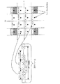
図1の左側の図は、送信フレーム中のデータ領域をデータビット列として表している。16QAM(Quadrature Amplitude Modulation:16値直交振幅変調)の場合、送信フレーム中のデータ領域によって伝送される送信データは、Nビット(N=4)毎のシンボルの集合である。この送信データ中の少なくともいずれかのシンボルの下位Mビット(M=N―2=2)の各ビットに1の値を持つREPETITIONビットをマッピングする。ここで、REPETITIONビットとは、送信データのサイズを送信フレームのデータ領域のサイズに合わせるために送信データに挿入されるダミービットの一例である。
【0008】
16QAMにおけるシンボルの信号配置は、図1の右側のようになる。信号配置図のシンボルの信号点は16点存在し、一般的にQAMの場合、1シンボル(4ビット)のデータのうち、1ビットの誤りに対して極力誤りが小さくなるように、隣り合うシンボルを構成するビットは1ビットだけ違うように配置されている。例えば、16QAMの信号点(1,0,0,0)の周囲四点は、(1,0,1,0)、(1,1,0,0)、(0,0,0,0)、(1,0,0,1)となっており、信号点(1,0,0,0)と各々3ビット目、2ビット目、1ビット目、4ビット目が相違する。このように、信号配置図では、いずれか1ビットの値が異なるシンボル同士を隣り合わせる規則に従って複数のシンボルを2次元に配置する。
3GPP、HSDPAでは図1、図2、図17に示した信号点配置が用いられている。しかし、3GPP、HSDPAに限らない場合には、上記のいずれか1ビットの値が異なるシンボル同士を隣り合わせるという条件を満たすのであれば、シンボルの配置は、図1等に示した信号配置に限定されるものではない。
【0009】
図1に示すように、右側の各シンボルは、左側の信号配置図の値と同値の信号点に配置される。したがって、上述したように、送信データ中の少なくともいずれかのシンボルの下位Mビット(M=2)の各ビットに1の値を持つREPETITIONビットをマッピングすることにより、信号配置図上の4隅の信号点の下位2ビットが“1”で満たされているため、REPETITIONビットを下位2ビットに持つシンボルは信号配置図上の4隅の信号点に配置されることとなる。
このように、本実施の形態では、REPETITIONビットを“1”と置き換えて1シンボルの下位2ビットに配置することにより多値変調方式による送信での誤り率を低下する事を可能とする。
【0010】
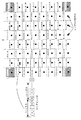
図2は、1シンボルが6ビットである64QAMの場合のデータビット列とシンボルの信号配置について示した図である。図2の右図と左図の対応は、図1と同様である。
なお、図2、図9、図11、図14、図17に示されているデータビット列はすべて送信フレーム中のデータ領域を表している。
【0011】
次に、本実施の形態の多値変調装置1及び多値復調装置2の構成図を図3及び図4に示す。
多値変調装置1は複数のシンボルから構成されたデータを多値変調して送信する。多値復調装置2は複数のシンボルから構成されたデータを受信して多値復調する。
多値変調装置1は送信データ生成部11、送信データ生成部11で生成された送信データに対してチャネルコーディング処理を行い、またRATE−MATCHINGにより生じるREPETITIONビットのマッピング処理を行なうコーディング処理部12、変調処理を行なう変調部13、変調部13により変調されたデータをアンテナ15から無線送信させる送信部(RF)14により構成されている。
また、多値復調装置2はアンテナ16を用いて変調されたデータを受信する受信部(RF)17、受信部17より受信されたデータを復調する復調部18、復調部18によって復調されたデータに対してREPETITIONビットを除去し、デコーディング処理を行うデコーディング処理部19により構成されている。
【0012】
まず、多値変調装置1の動作について述べる。ここでは16QAMの場合を例にして述べる。
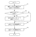
図5は、複数のシンボルから構成された送信データが生成されてから送信されるまでの多値変調装置1の動作を示すフローチャートである。
まず、多値変調装置1の送信データ生成部11は、複数のシンボルで構成されたデータビット列である送信データを生成する(ステップST1)。
コーディング処理部12では、コーディング処理及びREPETITIONビットが生成された場合に“1”と置き換えてシンボルの所定の位置へのマッピングを行う(ステップST2、ST3)。ここで、1の値を持ったREPETITIONビットを生成するようにしてもよい。この場合には、REPETITIONビットが生成された場合に“1”と置き換える動作が不要になる。
上記シンボルの所定の位置の一例としては、シンボルの下位2ビットに1の値を持ったREPETITIONビットが配置されるようにマッピングする方法がある。
【0013】
上記のように、コーディング処理部12は、送信データ生成部11が生成した送信データ(データビット列)のビット数と送信データを送信する送信フレーム中のデータ領域のビット数とを比較し、送信データのビット数が送信フレーム中のデータ領域のビット数に満たないビット数分、REPETITIONビットを所定位置にマッピングし、マッピング後の送信データを所定ビット数からなる複数のシンボルに分割した結果、REPETITIONビットを少なくともいずれかのシンボルの特定のビット位置にマッピングさせることにより送信データをコーディングする。このため、REPETITIONビットをマッピングされたシンボルはIQ座標を持つ信号配置図の最も外側である4隅に配置され、送信することが可能となる。
IQ座標を持つ信号配置図では、より外側の信号点にREPETITIONビットを含むシンボルが配置される方が、送信データの誤り率が低下するという特徴が存在する。従って、REPETITIONビットを含んだシンボルを信号配置図の最も外側である4隅に配置することで、送信データの誤り率を最も低下させることができる。
【0014】
次に、変調部13は、図5に示すようにコーディング処理部12によってマッピングされた送信データのデータビット列を多値変調する(ステップST4)。
送信部14は、変調部13により変調された送信データをアンテナ15から無線送信させる(ステップST5)。
【0015】
次に、図5のST2及びST3で示したコーディング処理部12の動作を詳細に説明する。
図7は、コーディング処理部12の具体的動作を示す。P1では送信データに対して信頼度情報を付加する。信頼度情報の一例としては、CRC(Cyclic Redundancy Check:巡回冗長検査値)が挙げられる。
P2では送信フレームのデータ領域のサイズによって送信データ(CODE BLOCK)の分割処理を行う。すなわち、送信データを複数のシンボル(信号)に分割する。
P3では分割された送信データに対して符号化処理を行う。
P4ではRATE−MATCHING処理が行なわれREPETITIONビットが生成される。
REPETITIONビットが生成された場合、本実施の形態の発明では、発生するREPETITIONビットの抽出処理を行なう(P10)。
REPETITIONビットの生成でない場合、REPETITIONビットを除いたデータについてPHCH(PHysical CHannel)数に応じた送信データ分割処理(P5)を行い、P6にて送信中のバースト誤りに対応する為のHS−DSCHインターリーブ処理を行う。
P6の処理終了後、REPETITIONビットを“1”に変換して送信データの最終シンボルから順にREPETITIONビット数分がREPETITIONビットをマッピングする(P7)。
【0016】
REPETITIONビットのマッピングは図8に示すようにREPETITIONされたビット数Nに対してシンボル数=N/2(N%2>0の場合はN+1)についてマッピング処理がされる。
N%2>0の場合には余剰ビットについて1シンボルに対して右詰めで、かつ、最終シンボルからマッピング処理を行う。インターリーブ処理後の送信データのビット列に対し、REPETITIONビットをマッピング処理した図を図9に示す。ただし、図8、図9では、N/2シンボル中にREPETITIONビットがマッピングされたが、これはREPETITIONビットのマッピング方法の一例であり、REPETITIONビットは、送信データ(情報ビット)の所定の位置に、マッピングされればよい。
Physical CHannelのマッピング処理後(P8)、ビットリアレンジメント(BIT−REARRANGEMENT) FOR 16QAMを行い(P9)、変調部13へデータを転送する。
【0017】
次に、多値復調装置2の動作について、16QAMの場合を例にして述べる。
図6は多値復調装置2が多値変調装置1から送信されたデータを受信し、処理するフローチャートである。
多値変調装置1がデータを送信すると多値復調装置2の受信部17は、そのデータを受信する(ステップST11)。復調部18は受信部17がデータを受信すると、そのデータを復調する(ステップST12)。
ステップST11で、受信部17は、予め定められたマッピングの条件に基づいてREPETITIONビットを所定位置にマッピングした送信データを受信する。
デコーディング処理部19では、復調部18が受信データを復調するとそのデータからREPETITIONビットを取り除き、デコーディング処理を行う(ステップST13、ST14、ST15)。どのシンボルにREPETITIONビットがマッピングされているかは事前に通知される情報から算出する。具体的には、ステップ13で、デコーディング処理部は、予め定められたマッピングの条件と送信データにマッピングされたREPETITIONビットのビット数と送信データ全体のビット数とから送信データ中のREPETITIONビットの位置を算出し、算出した結果からREPETITIONビットがあるかを判断する。そして算出したREPETITIONビットの位置に基づいて上記復調部が復調した送信データからREPETITIONビットを除去する。
【0018】
以上、4値より大きい多値変調方式において無線フレームのデータビット数に合わせる為に生じるREPETITIONビットをシンボルの所定の場所にマッピングすることにより誤り率が低くなる信号点を選択し送信することを特徴とする変調方式について説明した。
【0019】
また、16QAMにおいて無線フレームのビット数に合わせる為に生じるREPETITIONビットを“1”と置き換えて1シンボルの下位2ビットにマッピングすることにより誤り率が低くなる信号点を選択する変調方式について説明した。
【0020】
また、REPETITIONビットのマッピング処理を最終データからマッピング可能なシンボル数分行う事を特徴とした変調方式について説明した。
【0021】
この実施の形態1では、REPETITIONビットをマッピングすることによりマッピングされたシンボルについてIQ座標の信号配置図における4隅に配置され、送信することが可能となる為、送信データの誤り率を低減することが可能となる。
【0022】
実施の形態2.
実施の形態1では1シンボルが4ビットの16QAMの場合のマッピング方式について述べた。本実施の形態では、図2に示すように1シンボルが6ビットの64QAMの場合について述べる。
64QAM送信の場合のコーディング処理部12の動作について説明する。64QAM送信の場合のコーディング処理部12の動作は、図6に示すように、基本的に64QAM送信の場合のコーディング処理部12の動作と同様である。
まず、P1で信頼度情報を付加し、P2では送信データ(情報ビット)のサイズによってデータの分割処理を行う。P3では送信データに対して符号化処理を行う。P4ではRATE−MATCHING処理が行なわれREPETITIONビットが生成される。ここで発生するREPETITIONビットの抽出処理を行なう(P10)。PhCH数に応じた、送信データ分割処理(P5)を経てP6にて送信中のバースト誤りに対応する為のインターリーブ処理を行なう。P6の処理終了後REPETITIONされたビットを“1”に置き換えてデータ最終シンボルからマッピング可能なシンボル数分マッピング処理を行う(P7)。マッピングはREPETITIONされたビット数Nに対してシンボル数=N/4(N%4>0の場合はN+1)についてマッピング処理が行なわれる。64QAMの場合のマッピング処理を図10に示す。また、インターリーブ処理後のデータビット列に対し、REPETITIONビットをマッピング処理した図を図11に示す。N%4>0の場合には余剰ビットについて1シンボルに対して右詰めでマッピング処理を行なう。図10、図11に示すマッピング処理は、基本的に図8、図9に示すマッピング処理と同様である。
【0023】
以上、64QAMにおいて無線フレームのビット数に合わせる為に生じるREPETITIONビットを“1”と置き換えて、1シンボルの下位4ビットにマッピングすることにより誤り率が低くなる信号点を選択する変調方式について説明した。
【0024】
データの最終シンボルからREPETITIONビットをマッピングするシンボル数分についてREPETITIONビットを“1”と置き換えてシンボルの下位4ビットに配置するようにマッピングすることにより信号点配置上の4隅に配置され送信することが可能となる為、誤り率の低減が可能となる。
【0025】
実施の形態3.
実施の形態1および実施の形態2では最終シンボルからマッピング可能なシンボル数迄のマッピング方法について示したが、本実施の形態ではデータ全体に対して均一に分散してREPETITIONビットをマッピングする多値変調方式について説明する。
図12は、16QAM、64QAM共に複数のシンボルに分散してREPETITIONビットを配置する処理構成を示す。
16QAMの場合、M1データシンボルおきに先頭シンボルからマッピングを行なう。ここでMは次式で求められる。
M1=(S+(N/4))/(N/2)
N:REPETITIONビット数、S:送信データ全体のシンボル数
64QAMの場合も同様に、M2データシンボル毎に先頭シンボルからマッピング処理を行なう。M2は次式で求められる。
M2=(S+(N/6))/(N/4)
N:REPETITIONビット数、S:送信データ全体のシンボル数
【0026】
以上、REPETITIONビットのマッピング処理を全データに対して極力均一に分散して行うことを特徴とする変調方式について説明した。
【0027】
実施の形態4.
本実施の形態では、1シンボルが4ビットの16QAMにおいてRATE−MATCHING処理にて生成されたREPETITIONビットが'0'で、かつ1シンボルの下位2ビットのうち少なくとも1ビットにREPETITIONビットが配置される場合にはそのREPETITIONビットを'1'に変更するばあいについて説明する。
本実施の形態の16QAMによる送信時の動作について述べる。図13は、コーディング処理部12の動作を示すフローチャートである。
P11では送信データに対して信頼度情報を付加する。P12では送信データ(情報データ)のサイズによってデータの分割処理を行う。P13では送信データに対して符号化処理を行う。P14ではRATE−MATCHING処理が行なわれREPETITIONビットが生成される。PHCH数に応じたデータ分割処理(P15)を行い、P16にて送信中のバースト誤りに対応する為のHS−DSCHインターリーブ処理を行なう。P16の処理終了後、REPETITIONビットが'0'で、かつREPETITIONされたビットで1シンボルの下位2ビットのうち少なくとも1ビットがREPETITIONビットになる条件を満たす場合にはREPETITIONビットを“1”に変換する処理を行う(P17)。PHYSICAL CHANNELマッピング処理後(P18)、BIT−REARRANGEMENT FOR 16QAMを行い(P19)変調部13へデータを転送する。
【0028】
この処理により、REPETITIONビットを置き換えた後の、16QAMにおけるデータシンボルの場合のシンボル信号点配置状態を図14に示す。
図14に示すように、RATE−MATCHING処理により生成されたREPETITIONビットが'0'であり、かつ信号点配置上の下位2ビットに少なくとも1ビット、REPETITIONビットを含む場合には本実施の形態ではREPETITIONビットを“1”と置き換える処理を行う。上記条件を満たさない場合にはRATE−MATCHINGにより生成されたREPETITIONビットをそのまま送信する。
【0029】
図15は、複数のシンボルからなる送信データを生成してからデータを送信するまでの多値変調装置1の動作フローチャートを示す。
まず、多値変調装置1の送信データ生成部11は複数のシンボルで構成された送信データ(データビット列)を生成する(ステップST21)。
コーディング処理部12では、コーディング処理及びRATE−MATCHING処理でREPETITIONビットを生成する(ステップST21)。生成されたREPETITIONビットが'0'の場合でかつ、シンボル中の下位2ビットのうち少なくとも1ビットに配置されている場合にはREPETITIONビットを1と置き換える処理を行う(ステップST22、ST23、ST24)。
図12に示すようにコーディング処理部12で発生したREPETITIONビットを1と置き換えて送信する為、シンボルはIQ座標の信号配置図における外側に配置され送信することが可能となる為、誤り率が小さいものになる。
変調部13はコーディング処理部12の処理を終えるとマッピング後のデータを多値変調する(ステップST25)。
送信部14は変調部13により変調された送信データをアンテナ15から無線送信する(ステップST26)。
【0030】
一方、図16は、多値復調装置2が多値変調装置1にて送信された送信データを受信し、処理するフローチャートである。
多値変調装置1が送信データを送信すると多値復調装置2の受信部17は、その送信データを受信する(ステップST31)。
復調部18は受信部17がデータを受信すると、その送信データを多値復調する(ステップST32)。デコーディング処理部19では復調部18が受信したデータを復調するとそのデータに対してデコーディング処理を行なう(ステップST33)。
【0031】
以上、多値変調方式において無線フレームのビット数に合わせる為に生じるREPETITIONビットを'0'から'1'に変換することにより誤り率が低くなる信号点を選択し送信することを特徴とする変調方式について説明した。
【0032】
また、16QAMにおいて無線フレームのビット数に合わせる為に生じるREPETITIONビットが0であり、かつ1シンボルの下位2ビットのうち少なくとも1ビットに配置される条件を満たす場合にはそのREPETITIONビットを'0'から'1'に変換する処理を行う変調方式について説明した。
【0033】
この実施の形態4に示す処理により信号点配置上の外側に信号点が配置される為、多値変調方式による送信時に誤り率を低下する事が可能となる。すなわちREPETITIONビットで上記条件を満たすシンボルについてはIQ座標における外側に配置され送信することが可能となる為、送信データの誤り率を低減することが可能となる。
【0034】
実施の形態5.
本実施の形態の64QAMによる送信時の動作について述べる。64QAMにおけるコーディング処理部12の基本的動作は、16QAMにおけるコーディング処理部12の動作と同様であり、図13のフローチャートで示すことが可能である。
P11では送信データに対して信頼度情報を付加する。P12では送信データ(情報データ)のサイズによってデータの分割処理を行う。P13では送信データに対して符号化処理を行う。P14ではRATE−MATCHING処理が行なわれREPETITIONビットが生成される。PHCH数に応じたデータ分割処理(P15)を行い、P16にて送信中のバースト誤りに対応する為のHS−DSCHインターリーブ処理を行なう。P16の処理終了後、REPETITIONビットが'0'で、かつREPETITIONされたビットで1シンボルの真中2ビットのうち少なくとも1ビットがREPETITIONビットになる条件を満たす場合にはREPETITIONビットを“1”に変換する処理を行う(P17)。PHYSICAL CHANNELマッピング処理後(P18)、ビットアレンジメント(BIT−REARRANGEMENT FOR 64QAM)を行い変調部13へデータを転送する。
【0035】
64QAMにおけるシンボルの場合には信号点配置は図17のようになる。図17よりRATE−MATCHING処理により生成されたREPETITIONビットが'0'であり、かつ信号点配置上の下位2ビットのうち少なくとも1ビットREPETITIONビットを含む場合には本実施の形態ではそのREPETITIONビットを“1”と置き換える処理を行う。このようにすることで、信号点配置上の外側にREPETITIONビットを含んだ信号点が配置する為、多値変調方式による送信時に誤り率を低下する事が可能となる。
一方、上記条件を満たさない場合にはRATE−MATCHINGにより生成されたREPETITIONビットをそのまま送信する。
【0036】
図18は複数シンボルが生成されてからデータ送信までのフローチャートである。
まず、多値変調装置1の送信データ生成部11は複数シンボルで構成されたデータビット列を生成する(ステップST41)。
コーディング処理部12ではコーディング処理及びRATE−MATCHING処理でREPETITIONビットを生成する(ステップST41)。
コーディング処理部12は、生成されたREPETITIONビットが'0'の場合でかつ、シンボル中の真中2ビットのうち少なくとも1ビットに配置される場合に“1”と置き換え処理を行う(ステップST42、ST43、ST44)。図17に示すようにコーディング処理部12で発生したREPETITIONビットを“1”と置き換えて送信する為、シンボルはIQ座標の信号配置図における外側に配置され送信することが可能となる為、誤り率が小さいものになる。
変調部13はコーディング処理部12の処理を終えると図17に示すようにマッピング後の送信データを多値変調する(ステップST45)。
送信部14は変調部13により変調された送信データをアンテナ15から無線送信させる(ステップST46)。
【0037】
一方、図16は、本実施の形態においても、多値変調装置にて送信されたデータを受信し、処理するフローチャートを示す。
多値変調装置1が送信データを送信すると多値復調装置2の受信部17は、その送信データを受信する(ステップST31)。
復調部18は受信部17が送信データを受信すると、その送信データを復調する(ステップST32)。
デコーディング処理部19では復調部18が受信データを復調するとそのデータに対してデコーディング処理を行なう(ステップST33)。
【0038】
以上、64QAMにおいて無線フレームのビット数に合わせる為に生じるREPETITIONビットが0であり、かつ1シンボルの真中2ビットのうち少なくとも1ビットに配置される条件を満たす場合にはそのREPETITIONビットを'0'から'1'に変換する変調方式について説明した。
【0039】
この実施の形態によりREPETITIONビットで上記条件を満たすシンボルについてはIQ座標の信号配置図における外側に配置され送信することが可能となる為、送信データの誤り率を低減することが可能となる。すなわち本実施の形態では、1シンボルが6ビットの64QAMにおいて図18に示すようにRATE−MATCHING処理にて生成されたREPETITIONビットが'0'で、かつ1シンボルの真中2ビットのうち少なくとも1ビットにREPETITIONビットが配置される場合にはそのREPETITIONビットを'1'に変更する。処理により多値変調によるデータ送信時に誤り率を低くすることが可能となる。
【0040】
図19は、多値変調装置1及び多値復調装置2のコンピュータ基本構成図である。
図19において、プログラムを実行するCPU(Central Processing Unit)400は、バス380を介してモニタ410、キーボード420、マウス430、通信ボード440、磁気ディスク装置460等と接続されている。
磁気ディスク装置460には、オペレーティングシステム(OS)470、プログラム群490、ファイル群500が記憶されている。ただし、プログラム群490、ファイル群500が一体となってオブジェクト指向のプログラム群490を形成する形態も一実施の形態として考えられる。
プログラム群490は、CPU400、OS470により実行される。
上記各実施の形態では、多値変調装置1及び多値復調装置2は、通信ボード440の機能を使用して送信及び受信を行う。
【0041】
すべての実施の形態では、各構成要素の各動作はお互いに関連しており、各構成要素の動作は、上記に示された動作の関連を考慮しながら、一連の動作として置き換えることができる。そして、このように置き換えることにより、方法の発明の実施形態とすることができる。
また、上記各構成要素の動作を、各構成要素の処理と置き換えることにより、プログラムの実施の形態とすることができる。
また、プログラムを、プログラムを記録したコンピュータ読み取り可能な記録媒体に記憶させることで、プログラムに記録したコンピュータ読み取り可能な記録媒体の実施の形態とすることができる。
【0042】
プログラムの実施の形態及びプログラムに記録したコンピュータ読み取り可能な記録媒体の実施の形態は、すべてコンピュータで動作可能なプログラムにより構成することができる。
プログラムの実施の形態およびプログラムを記録したコンピュータ読み取り可能な記録媒体の実施の形態における各処理はプログラムで実行されるが、このプログラムは、記録装置に記録されていて、記録装置から中央処理装置(CPU)に読み込まれ、中央処理装置によって、各フローチャートが実行されることになる。
また、各実施の形態のソフトウェアやプログラムは、ROM(READ ONLY MEMORY)に記憶されたファームウェアで実現されていても構わない。あるいは、ソフトウェアとファームウェアとハードウェアとの組み合わせで前述したプログラムの各機能を実現しても構わない。
【0043】
【発明の効果】
上記マッピング方式によれば、送信データの誤り率を低下させることができる。
【図面の簡単な説明】
【図1】 16QAMにおけるシンボルの信号配置図である。
【図2】 64QAMにおけるシンボルの信号配置図である。
【図3】 多値変調装置1の構成図である。
【図4】 多値復調装置2の構成図である。
【図5】 複数のシンボルから構成されたデータが生成されてからデータを送信するまでのフローチャート図である。
【図6】 多値変調装置11にて送信されたデータを多値復調装置2が受信し、処理するフローチャート図である。
【図7】 コーディング処理部のフローチャートである。
【図8】 16QAMの場合のマッピング処理図である。
【図9】 インターリーブ処理後のデータビット列に対し、REPETITIONビットをマッピング処理した図である。
【図10】 64QAMの場合のマッピング処理図である。
【図11】 インターリーブ処理後のデータビット列に対し、REPETITIONビットをマッピング処理した図である。
【図12】 16QAM、64QAM共に複数のシンボルに分散してREPETITIONビットを配置する処理構成図である。
【図13】 コーディング処理部のフローチャートである。
【図14】 REPETITIONビットを置き換えた後の16QAMにおけるデータシンボルの場合のシンボル信号配置図である。
【図15】 複数シンボルが生成されてからデータ送信までのフローチャート図である。
【図16】 多値変調装置1にて送信されたデータを受信し、処理するフローチャートである。
【図17】 64QAMにおけるシンボルの信号配置図である。
【図18】 複数シンボルが生成されてからデータ送信までのフローチャートである。
【図19】 多値変調装置1及び多値復調装置2のコンピュータ基本構成図である。
【符号の説明】
1 多値変調装置、2 多値復調装置、11 送信データ生成部、12 コーディング処理部、13 変調部、14 送信部、15,16 アンテナ、17 受信部、18 復調部、19 デコーディング処理部。[0001]
BACKGROUND OF THE INVENTION
The present invention relates to a mapping method for mapping dummy bits to transmission data.
[0002]
[Prior art]
According to 3GPP (3rd Generation Partnership Project) RELEASE 5, HS-DSCH (High Speed−) in HS-DPA (High Speed-Downlink Packet Access) downlink (transmission from BTS (base station) to MS (mobile station)). In the Downlink Shared Channel) transmission process, a REPETITION bit is generated by a data repetition process called REPETION to match the frame data size in the RATE-MATCHING process. The REPETITION bits are randomly arranged in the symbol (signal) through processing such as interleaving, and transmitted by a multi-level modulation method.
In the conventional coding method, since the REPETITION bits are randomly arranged in the symbol, there is a case where the error rate of the transmitted data does not decrease.
[0003]
An object of the present invention is to reduce the error rate for symbols mapped with REPETITION bits.
[0004]
[Non-Patent Document 1]
3GPP TR25.858 V5.0.0 (2002-03),
Internet (URL: http://www.3gpp.org)
[0005]
[Problems to be solved by the invention]
An object of the present invention is to reduce the error rate in transmission by performing a coding process in which a REPETITION bit is mapped to a predetermined place in one symbol in a multilevel modulation system. Another object of the present invention is to reduce the error rate in transmission by performing conversion processing on specific REPETITION bits.
[0006]
[Means for Solving the Problems]
The modulation device of the present invention is a modulation device that modulates transmission data,
A transmission data generation unit for generating transmission data;
The number of bits of the transmission data generated by the transmission data generation unit is compared with the number of bits of the data area in the transmission frame for transmitting the transmission data, and the number of bits of the transmission data becomes the number of bits of the data area in the transmission frame Dummy bits are mapped to predetermined positions for less than the number of bits, and the transmission data after mapping is divided into a plurality of symbols having a predetermined number of bits, so that the dummy bits are mapped to specific bit positions of at least one of the symbols. A coding processing unit for coding the transmission data.
[0007]
DETAILED DESCRIPTION OF THE INVENTION
In the invention of the following embodiment, a transmission method of the REPETION bit in the multi-level modulation method larger than four values will be described.
The diagram on the left side of FIG. 1 represents a data area in a transmission frame as a data bit string. In the case of 16QAM (Quadrature Amplitude Modulation), transmission data transmitted by a data area in a transmission frame is a set of symbols for every N bits (N = 4). A REPETITION bit having a value of 1 is mapped to each bit of the lower M bits (M = N−2 = 2) of at least one symbol in the transmission data. Here, the REPETITION bit is an example of a dummy bit inserted into the transmission data in order to match the size of the transmission data with the size of the data area of the transmission frame.
[0008]
The signal arrangement of symbols in 16QAM is as shown on the right side of FIG. There are 16 signal points of symbols in the signal layout diagram. Generally, in the case of QAM, adjacent symbols are used so that the error is minimized as much as possible for 1-bit error in 1-symbol (4-bit) data. Are arranged so that only one bit is different. For example, the four surrounding points of a 16QAM signal point (1, 0, 0, 0) are (1, 0, 1, 0), (1, 1, 0, 0), (0, 0, 0, 0). , (1, 0, 0, 1), the signal point (1, 0, 0, 0) is different from the third bit, the second bit, the first bit, and the fourth bit, respectively. In this way, in the signal arrangement diagram, a plurality of symbols are arranged two-dimensionally according to a rule for adjoining symbols having different values of any one bit.
In 3GPP and HSDPA, the signal point arrangement shown in FIGS. 1, 2, and 17 is used. However, when not limited to 3GPP and HSDPA, the symbol arrangement is limited to the signal arrangement shown in FIG. Is not to be done.
[0009]
As shown in FIG. 1, each symbol on the right side is arranged at a signal point having the same value as the value in the signal arrangement diagram on the left side. Therefore, as described above, by mapping the REPETION bit having a value of 1 to each bit of the lower M bits (M = 2) of at least one of the symbols in the transmission data, the four corners on the signal arrangement diagram are displayed. Since the lower 2 bits of the signal point are filled with “1”, the symbols having the REPETTION bit in the lower 2 bits are arranged at the signal points at the four corners on the signal arrangement diagram.
As described above, in this embodiment, the REPETTION bit is replaced with “1” and arranged in the lower 2 bits of one symbol, so that it is possible to reduce the error rate in transmission using the multi-level modulation scheme.
[0010]
FIG. 2 is a diagram showing a data bit sequence and symbol signal arrangement in the case of 64QAM in which one symbol is 6 bits. The correspondence between the right diagram and the left diagram in FIG. 2 is the same as that in FIG.
2, 9, 11, 14, and 17 all represent data areas in the transmission frame.
[0011]
Next, the configuration diagrams of the
The
The
The multilevel demodulator 2 also includes a receiver (RF) 17 that receives data modulated using the
[0012]
First, the operation of the
FIG. 5 is a flowchart showing the operation of the
First, the transmission data generation unit 11 of the
When the
As an example of the predetermined position of the symbol, there is a method of mapping so that a REPETITION bit having a value of 1 is arranged in the lower 2 bits of the symbol.
[0013]
As described above, the
In the signal arrangement diagram having IQ coordinates, there is a feature that the error rate of the transmission data is reduced when the symbol including the REPETITION bit is arranged at the outer signal point. Therefore, the error rate of transmission data can be reduced most by arranging symbols including REPETITION bits at the four outer corners of the signal arrangement diagram.
[0014]
Next, the
The
[0015]
Next, the operation of the
FIG. 7 shows a specific operation of the
In P2, transmission data (CODE BLOCK) is divided according to the size of the data area of the transmission frame. That is, the transmission data is divided into a plurality of symbols (signals).
In P3, the divided transmission data is encoded.
In P4, RATE-MATCHING processing is performed and a REPETTION bit is generated.
When the REPETITION bit is generated, in the invention of this embodiment, extraction processing of the generated REPETITION bit is performed (P10).
If the REPETITION bit is not generated, transmission data division processing (P5) corresponding to the number of PHCHs (PHysical CHannel) is performed on the data excluding the REPETIONION bit, and HS-DSCH interleaving for responding to the burst error being transmitted at P6 Process.
After the process of P6 is completed, the REPETION bit is converted to “1”, and the REPETION bits are mapped in order from the last symbol of the transmission data (P7).
[0016]
As shown in FIG. 8, the mapping of the REPETION bits is performed with respect to the number N of REPETION bits for the number of symbols = N / 2 (N + 1 when N% 2> 0).
When N% 2> 0, the surplus bits are right-justified with respect to one symbol and mapping processing is performed from the last symbol. FIG. 9 is a diagram in which the REPETION bit is mapped to the bit string of the transmission data after the interleaving process. However, in FIG. 8 and FIG. 9, the REPETION bit is mapped in the N / 2 symbol, but this is an example of the mapping method of the REPETION bit, and the REPETION bit is located at a predetermined position of the transmission data (information bit). Mapping is sufficient.
After the physical channel mapping process (P8), bit rearrangement (BIT-REARRANGEMENT) FOR 16QAM is performed (P9), and the data is transferred to the
[0017]
Next, the operation of the multilevel demodulator 2 will be described by taking the case of 16QAM as an example.
FIG. 6 is a flowchart in which the multilevel demodulator 2 receives and processes the data transmitted from the
When the
In step ST11, the receiving
In the
[0018]
As described above, a signal point with a low error rate is selected and transmitted by mapping the REPETITION bits generated in order to match the number of data bits of a radio frame in a multilevel modulation scheme greater than four values, to a predetermined location of the symbol. The modulation method is described.
[0019]
Also, a modulation scheme has been described in which a REPETTION bit generated in order to match the number of bits of a radio frame in 16QAM is replaced with “1” and mapped to lower 2 bits of one symbol to select a signal point with a low error rate.
[0020]
Further, the modulation scheme characterized in that the mapping process of the REPETION bit is performed for the number of symbols that can be mapped from the final data has been described.
[0021]
In the first embodiment, symbols mapped by mapping the REPETATION bits are arranged at the four corners of the IQ coordinate signal arrangement diagram, and can be transmitted, so that the error rate of transmission data is reduced. Is possible.
[0022]
Embodiment 2. FIG.
In the first embodiment, the mapping method in the case of 16QAM in which one symbol is 4 bits has been described. In this embodiment, as shown in FIG. 2, a case where one symbol is 6 bits of 64QAM will be described.
An operation of the
First, reliability information is added at P1, and data division processing is performed according to the size of transmission data (information bits) at P2. In P3, the transmission data is encoded. In P4, RATE-MATCHING processing is performed and a REPETTION bit is generated. Extraction processing of REPETITION bits generated here is performed (P10). An interleaving process for responding to a burst error being transmitted at P6 is performed through a transmission data division process (P5) corresponding to the number of PhCHs. After the process of P6 is completed, the REPETITION bit is replaced with “1”, and the mapping process is performed for the number of symbols that can be mapped from the last data symbol (P7). Mapping is performed with respect to the number N of REPETITION for the number of symbols = N / 4 (N + 1 when N% 4> 0). The mapping process in the case of 64QAM is shown in FIG. FIG. 11 is a diagram in which the REPETION bit is mapped to the data bit string after the interleaving process. In the case of N% 4> 0, the surplus bits are mapped to the right with respect to one symbol. The mapping process shown in FIGS. 10 and 11 is basically the same as the mapping process shown in FIGS.
[0023]
As described above, the modulation method for selecting a signal point with a low error rate by replacing the REPETITION bit generated to match the number of bits of the radio frame in 64QAM with “1” and mapping it to the lower 4 bits of one symbol has been described. .
[0024]
For the number of symbols to which the REPETION bits are mapped from the last symbol of the data, the REPETITION bits are replaced with “1” and mapped so as to be arranged in the lower 4 bits of the symbol, and are arranged and transmitted at the four corners on the signal point arrangement. Therefore, the error rate can be reduced.
[0025]
Embodiment 3 FIG.
In the first and second embodiments, the mapping method from the last symbol to the number of symbols that can be mapped has been shown, but in this embodiment, multilevel modulation that maps the REPETITION bits uniformly distributed over the entire data The method will be described.
FIG. 12 shows a processing configuration in which the REPETITION bits are distributed in a plurality of symbols for both 16QAM and 64QAM.
In the case of 16QAM, mapping is performed from the first symbol every M1 data symbols. Here, M is obtained by the following equation.
M1 = (S + (N / 4)) / (N / 2)
N: number of REPETTION bits, S: number of symbols of the entire transmission data
Similarly, in the case of 64QAM, mapping processing is performed from the head symbol for each M2 data symbol. M2 is obtained by the following equation.
M2 = (S + (N / 6)) / (N / 4)
N: number of REPETTION bits, S: number of symbols of the entire transmission data
[0026]
In the above, the modulation method characterized in that the mapping process of the REPETION bit is performed as uniformly as possible with respect to all data has been described.
[0027]
Embodiment 4 FIG.
In this embodiment, the REPETTION bit generated by the RATE-MATCHING process in 16QAM in which one symbol is 4 bits is “0”, and the REPETION bit is arranged in at least one of the lower 2 bits of one symbol. In this case, the case where the REPETITION bit is changed to “1” will be described.
The operation at the time of transmission by 16QAM of this embodiment will be described. FIG. 13 is a flowchart showing the operation of the
In P11, reliability information is added to the transmission data. In P12, data division processing is performed according to the size of transmission data (information data). In P13, the transmission data is encoded. In P14, RATE-MATCHING processing is performed and a REPETTION bit is generated. Data division processing (P15) according to the number of PHCHs is performed, and HS-DSCH interleaving processing for responding to burst errors being transmitted is performed at P16. After the processing of P16 is completed, if the REPETITION bit is '0' and the REPETITION bit satisfies the condition that at least one bit of the lower 2 bits of one symbol is the REPETITION bit, the REPETIONION bit is converted to “1”. (P17). After the PHYSICAL CHANNEL mapping process (P18), BIT-REARRANGEMENT FOR 16QAM is performed (P19), and the data is transferred to the
[0028]
FIG. 14 shows the symbol signal point arrangement state in the case of a data symbol in 16QAM after the REPETITION bit is replaced by this processing.
As shown in FIG. 14, in the case where the REPETATION bit generated by the RATE-MATCHING process is “0” and the lower two bits on the signal point arrangement include at least one bit and the REPETION bit, Processing to replace the REPETITION bit with “1” is performed. If the above condition is not satisfied, the REPETITION bit generated by RATE-MATCHING is transmitted as it is.
[0029]
FIG. 15 shows an operation flowchart of the
First, the transmission data generation unit 11 of the
The
As shown in FIG. 12, since the REPETION bit generated in the
When the processing of the
The
[0030]
On the other hand, FIG. 16 is a flowchart in which the multilevel demodulator 2 receives and processes transmission data transmitted by the
When
When the receiving
[0031]
As described above, modulation is characterized in that a signal point with a low error rate is selected and transmitted by converting a REPETITION bit generated in order to match the number of bits of a radio frame in a multilevel modulation system from '0' to '1'. The method was explained.
[0032]
Further, if the REPETION bit generated to match the number of bits of the radio frame in 16QAM is 0 and the condition of being arranged in at least one bit of the lower 2 bits of one symbol is satisfied, the REPETION bit is set to “0”. The modulation method for performing the conversion from “1” to “1” has been described.
[0033]
Since the signal points are arranged outside the signal point arrangement by the processing shown in the fourth embodiment, it is possible to reduce the error rate at the time of transmission by the multi-level modulation method. That is, symbols satisfying the above conditions with the REPETTION bit can be arranged outside the IQ coordinates and transmitted, so that the error rate of transmission data can be reduced.
[0034]
Embodiment 5 FIG.
The operation at the time of transmission by 64QAM of this embodiment will be described. The basic operation of the
In P11, reliability information is added to the transmission data. In P12, data division processing is performed according to the size of transmission data (information data). In P13, the transmission data is encoded. In P14, RATE-MATCHING processing is performed and a REPETTION bit is generated. Data division processing (P15) according to the number of PHCHs is performed, and HS-DSCH interleaving processing for responding to burst errors being transmitted is performed at P16. After the processing of P16 is completed, if the REPETITION bit is '0' and the REPETITION bit satisfies the condition that at least one bit out of the two middle bits of the REPETITION bit is a REPETITION bit, the REPETITION bit is converted to “1”. (P17). After the PHYSICAL CHANNEL mapping process (P18), bit arrangement (BIT-REARRANGEMENT FOR 64QAM) is performed and data is transferred to the
[0035]
In the case of symbols in 64QAM, the signal point arrangement is as shown in FIG. From FIG. 17, when the REPETATION bit generated by the RATE-MATCHING process is “0” and includes at least one REPETION bit among the lower 2 bits on the signal point arrangement, in this embodiment, the REPETION bit is Performs replacement with “1”. In this way, since the signal point including the REPETITION bit is arranged outside the signal point arrangement, it is possible to reduce the error rate at the time of transmission by the multi-level modulation method.
On the other hand, if the above condition is not satisfied, the REPETITION bit generated by RATE-MATCHING is transmitted as it is.
[0036]
FIG. 18 is a flowchart from generation of a plurality of symbols to data transmission.
First, the transmission data generation unit 11 of the
The
The
When the processing of the
The
[0037]
On the other hand, FIG. 16 also shows a flowchart for receiving and processing data transmitted by the multi-level modulation device in the present embodiment.
When
When the receiving
In the
[0038]
As described above, when the REPETECTION bit generated to match the number of bits of the radio frame in 64QAM is 0 and the condition of being arranged in at least one bit of the two middle bits of one symbol is satisfied, the REPETION bit is set to “0”. A modulation scheme for converting from 1 to '1' has been described.
[0039]
According to this embodiment, a symbol satisfying the above condition with the REPETTION bit can be arranged and transmitted outside the signal arrangement diagram of the IQ coordinate, so that the error rate of transmission data can be reduced. That is, in this embodiment, in 64QAM in which one symbol is 6 bits, as shown in FIG. 18, the REPETTION bit generated by the RATE-MATCHING process is “0” and at least one bit of the middle two bits of one symbol When the REPETITION bit is arranged in the field, the REPETITION bit is changed to “1”. The processing can reduce the error rate during data transmission by multi-level modulation.
[0040]
FIG. 19 is a computer basic configuration diagram of the
In FIG. 19, a CPU (Central Processing Unit) 400 that executes a program is connected to a
The
The
In each of the above embodiments, the
[0041]
In all the embodiments, each operation of each component is related to each other, and the operation of each component can be replaced as a series of operations in consideration of the relationship of the operations described above. And it can be set as embodiment of method invention by replacing in this way.
Further, by replacing the operation of each component described above with the process of each component, the program can be implemented.
Further, by storing the program in a computer-readable recording medium in which the program is recorded, an embodiment of a computer-readable recording medium recorded in the program can be obtained.
[0042]
The embodiment of the program and the embodiment of the computer-readable recording medium recorded in the program can be configured by a computer-operable program.
Each processing in the embodiment of the program and the embodiment of the computer-readable recording medium on which the program is recorded is executed by the program, and this program is recorded in the recording device, and the central processing device ( CPU) and each flowchart is executed by the central processing unit.
In addition, the software and program of each embodiment may be realized by firmware stored in a ROM (READ ONLY MEMORY). Alternatively, each function of the program described above may be realized by a combination of software, firmware, and hardware.
[0043]
【The invention's effect】
According to the mapping method, the error rate of transmission data can be reduced.
[Brief description of the drawings]
FIG. 1 is a signal arrangement diagram of symbols in 16QAM.
FIG. 2 is a signal arrangement diagram of symbols in 64QAM.
3 is a configuration diagram of a
FIG. 4 is a configuration diagram of the multi-level demodulation device 2;
FIG. 5 is a flowchart from generation of data composed of a plurality of symbols to transmission of data.
FIG. 6 is a flowchart diagram in which the multi-level demodulation device 2 receives and processes data transmitted by the multi-level modulation device 11;
FIG. 7 is a flowchart of a coding processing unit.
FIG. 8 is a mapping process diagram in the case of 16QAM.
FIG. 9 is a diagram in which a REPETION bit is mapped to a data bit string after interleaving processing.
FIG. 10 is a mapping process diagram in the case of 64QAM.
FIG. 11 is a diagram in which a REPETTION bit is mapped to a data bit string after interleave processing.
FIG. 12 is a processing configuration diagram in which REPETITION bits are distributed in a plurality of symbols for both 16QAM and 64QAM.
FIG. 13 is a flowchart of a coding processing unit.
FIG. 14 is a symbol signal arrangement diagram in the case of a data symbol in 16QAM after replacing a REPETITION bit.
FIG. 15 is a flowchart from data generation to data transmission.
16 is a flowchart for receiving and processing data transmitted by the
FIG. 17 is a signal arrangement diagram of symbols in 64QAM.
FIG. 18 is a flowchart from generation of a plurality of symbols to data transmission.
FIG. 19 is a basic computer configuration diagram of the
[Explanation of symbols]
DESCRIPTION OF
Claims (12)
送信データを生成する送信データ生成部と、
上記送信データ生成部が生成した送信データのビット数と上記送信データを送信する送信フレーム中のデータ領域のビット数とを比較し、送信データのビット数が送信フレーム中のデータ領域のビット数に満たないビット数分、ダミービットを所定位置にマッピングし、マッピング後の送信データを所定ビット数からなる複数のシンボルに分割した結果、ダミービットを少なくともいずれかのシンボルの特定のビット位置にマッピングさせることにより送信データをコーディングするコーディング処理部とを備え、
上記コーディング処理部は、各々1の値を持つ複数のダミービットを送信データの所定位置にマッピングすることによって少なくともいずれかのシンボルの特定のビット位置に複数のダミービットをマッピングさせることを特徴とする変調装置。A modulation device for modulating transmission data,
A transmission data generation unit for generating transmission data;
The number of bits of the transmission data generated by the transmission data generation unit is compared with the number of bits of the data area in the transmission frame for transmitting the transmission data, and the number of bits of the transmission data becomes the number of bits of the data area in the transmission frame. Dummy bits are mapped to predetermined positions for less than the number of bits, and the transmission data after mapping is divided into a plurality of symbols having a predetermined number of bits, so that the dummy bits are mapped to specific bit positions of at least one of the symbols. e Bei a coding processor for coding the transmission data by,
The coding processing unit maps a plurality of dummy bits to specific bit positions of at least one symbol by mapping a plurality of dummy bits each having a value of 1 to a predetermined position of transmission data. Modulation device.
送信データを生成する送信データ生成部と、
上記送信データ生成部が生成した送信データのビット数と上記送信データを送信する送信フレーム中のデータ領域のビット数とを比較し、送信データのビット数が送信フレーム中のデータ領域のビット数に満たないビット数分、ダミービットを所定位置にマッピングし、マッピング後の送信データを所定ビット数からなる複数のシンボルに分割した結果、ダミービットを少なくともいずれかのシンボルの特定のビット位置にマッピングさせることにより送信データをコーディングするコーディング処理部とを備えた変調装置と、
上記変調装置によってダミービットがマッピングされた送信データを受信する受信部と、
予め定められたダミービットのマッピング条件と上記送信データに挿入されたダミービットのビット数と上記送信データのビット数とから上記受信部が受信した送信データ中のダミービットの位置を算出し、算出したダミービットの位置に基づいて上記復調部が復調した送信データからダミービットを除去することにより送信データをデコーディングするデコーディング処理部とを備えた復調装置とを備え、
上記変調装置のコーディング処理部は、各々1の値を持つ複数のダミービットを送信データの所定位置にマッピングすることによって少なくともいずれかのシンボルの特定のビット位置に複数のダミービットをマッピングさせることを特徴とする変復調システム。A modulation / demodulation system comprising a modulation device that modulates transmission data and a demodulation device that receives and demodulates transmission data modulated by the modulation device,
A transmission data generation unit for generating transmission data;
The number of bits of the transmission data generated by the transmission data generation unit is compared with the number of bits of the data area in the transmission frame for transmitting the transmission data, and the number of bits of the transmission data becomes the number of bits of the data area in the transmission frame. Dummy bits are mapped to predetermined positions for less than the number of bits, and the transmission data after mapping is divided into a plurality of symbols having a predetermined number of bits, so that the dummy bits are mapped to specific bit positions of at least one of the symbols. A modulation device comprising a coding processing unit for coding transmission data by
A receiving unit that receives transmission data in which dummy bits are mapped by the modulation device;
The dummy bit position in the transmission data received by the receiving unit is calculated from the predetermined dummy bit mapping condition, the number of dummy bits inserted in the transmission data, and the number of transmission data bits, and the calculation is performed. based on the position of the dummy bit e Bei a demodulation apparatus and a decoding processing unit for the demodulator to decode the transmitted data by removing the dummy bits from the transmission data demodulated who,
The coding processing unit of the modulation device maps a plurality of dummy bits to a specific bit position of at least one symbol by mapping a plurality of dummy bits each having a value of 1 to a predetermined position of transmission data. A characteristic modulation / demodulation system.
上記生成した送信データのビット数と上記送信データを送信する送信フレーム中のデータ領域のビット数とを比較し、送信データのビット数が送信フレーム中のデータ領域のビット数に満たないビット数分、各々1の値を持つ複数のダミービットを送信データの所定位置にマッピングし、マッピング後の送信データを所定ビット数からなる複数のシンボルに分割した結果、複数のダミービットを少なくともいずれかのシンボルの特定のビット位置にマッピングさせることにより送信データをコーディングし、
上記コーディングした送信データを変調する変調方法。Generate transmission data,
Compare the number of bits of the generated transmission data with the number of bits of the data area in the transmission frame that transmits the transmission data, and the number of bits of the transmission data is less than the number of bits of the data area in the transmission frame. , Mapping a plurality of dummy bits each having a value of 1 to a predetermined position of transmission data, and dividing the transmission data after mapping into a plurality of symbols having a predetermined number of bits, so that the plurality of dummy bits is at least one of the symbols Coding the transmitted data by mapping to specific bit positions of
A modulation method for modulating the coded transmission data.
上記生成した送信データのビット数と上記送信データを送信する送信フレーム中のデータ領域のビット数とを比較し、送信データのビット数が送信フレーム中のデータ領域のビット数に満たないビット数分、各々1の値を持つ複数のダミービットを送信データの所定位置にマッピングし、マッピング後の送信データを所定ビット数からなる複数のシンボルに分割した結果、複数のダミービットを少なくともいずれかのシンボルの特定のビット位置にマッピングさせることにより送信データをコーディングする処理と、
上記コーディングした送信データを変調する処理とをコンピュータに実行させる変調プログラム。Processing to generate transmission data;
Compare the number of bits of the generated transmission data with the number of bits of the data area in the transmission frame that transmits the transmission data, and the number of bits of the transmission data is less than the number of bits of the data area in the transmission frame. , Mapping a plurality of dummy bits each having a value of 1 to a predetermined position of transmission data, and dividing the transmission data after mapping into a plurality of symbols having a predetermined number of bits, so that the plurality of dummy bits is at least one of the symbols Coding transmission data by mapping to specific bit positions of
A modulation program for causing a computer to execute processing for modulating the coded transmission data.
上記生成した送信データのビット数と上記送信データを送信する送信フレーム中のデータ領域のビット数とを比較し、送信データのビット数が送信フレーム中のデータ領域のビット数に満たないビット数分、各々1の値を持つ複数のダミービットを送信データの所定位置にマッピングし、マッピング後の送信データを所定ビット数からなる複数のシンボルに分割した結果、複数のダミービットを少なくともいずれかのシンボルの特定のビット位置にマッピングさせることにより送信データをコーディングする処理と、
上記コーディングした送信データを変調する処理とをコンピュータに実行させるための変調プログラムを記録したコンピュータ読み取り可能な記録媒体。Processing to generate transmission data;
Compare the number of bits of the generated transmission data with the number of bits of the data area in the transmission frame that transmits the transmission data, and the number of bits of the transmission data is less than the number of bits of the data area in the transmission frame. , Mapping a plurality of dummy bits each having a value of 1 to a predetermined position of transmission data, and dividing the transmission data after mapping into a plurality of symbols having a predetermined number of bits, so that the plurality of dummy bits is at least one of the symbols Coding transmission data by mapping to specific bit positions of
A computer-readable recording medium recording a modulation program for causing a computer to execute the process of modulating the coded transmission data.
Priority Applications (5)
| Application Number | Priority Date | Filing Date | Title |
|---|---|---|---|
| JP2002317489A JP3810360B2 (en) | 2002-10-31 | 2002-10-31 | Modulation apparatus, modulation / demodulation system, modulation method, modulation program, and computer-readable recording medium recording the modulation program |
| PCT/JP2003/007964 WO2004040871A1 (en) | 2002-10-31 | 2003-06-24 | Modulation device, demodulation device, modulation/demodulation system, modulation method, demodulation method, modulation program, computer-readable recording medium containing the modulation program, demodulation program, and computer-readable recording medium containing the demodulation program |
| US10/498,233 US20050008081A1 (en) | 2002-10-31 | 2003-06-24 | Modulation device, demodulation device, modulation/demodulation system, modulation method, demodulation method, modulation program and computer readable recording containing the modulation program demodulation program and computer- readable recording medium containing the demodulation program |
| CN03801542.0A CN1593045A (en) | 2002-10-31 | 2003-06-24 | Modulation device, demodulation device, modulation/demodulation system, modulation method, demodulation method, modulation program and computer-readable recording medium containing the modulation prog |
| EP03809837A EP1453264A1 (en) | 2002-10-31 | 2003-06-24 | Modulation device, demodulation device, modulation/demodulation system, modulation method, demodulation method, modulation program, computer-readable recording medium containing the modulation program, demodulation program, and computer-readable recording medium containing the demodulation program |
Applications Claiming Priority (1)
| Application Number | Priority Date | Filing Date | Title |
|---|---|---|---|
| JP2002317489A JP3810360B2 (en) | 2002-10-31 | 2002-10-31 | Modulation apparatus, modulation / demodulation system, modulation method, modulation program, and computer-readable recording medium recording the modulation program |
Publications (2)
| Publication Number | Publication Date |
|---|---|
| JP2004153628A JP2004153628A (en) | 2004-05-27 |
| JP3810360B2 true JP3810360B2 (en) | 2006-08-16 |
Family
ID=32211721
Family Applications (1)
| Application Number | Title | Priority Date | Filing Date |
|---|---|---|---|
| JP2002317489A Expired - Fee Related JP3810360B2 (en) | 2002-10-31 | 2002-10-31 | Modulation apparatus, modulation / demodulation system, modulation method, modulation program, and computer-readable recording medium recording the modulation program |
Country Status (5)
| Country | Link |
|---|---|
| US (1) | US20050008081A1 (en) |
| EP (1) | EP1453264A1 (en) |
| JP (1) | JP3810360B2 (en) |
| CN (1) | CN1593045A (en) |
| WO (1) | WO2004040871A1 (en) |
Families Citing this family (8)
| Publication number | Priority date | Publication date | Assignee | Title |
|---|---|---|---|---|
| DE602004018489D1 (en) * | 2003-05-16 | 2009-01-29 | Thomson Licensing | DEMODULATION AND REPEAT DECODING OF MULTILAYER SIGNALS |
| EP1898544A1 (en) * | 2005-07-29 | 2008-03-12 | Matsushita Electric Industrial Co., Ltd. | Multicarrier transmitting apparatus, multicarrier receiving apparatus, and their methods |
| JP4912311B2 (en) | 2005-08-05 | 2012-04-11 | パナソニック株式会社 | Wireless communication apparatus and wireless communication method |
| KR20090125188A (en) * | 2007-03-21 | 2009-12-03 | 마벨 이스라엘 (엠.아이.에스.엘.) 리미티드 | Usf coding |
| US8254244B2 (en) * | 2007-10-30 | 2012-08-28 | Qualcomm Incorporated | Arrangement and method for transmitting control information in wireless communication systems |
| AU2009327618A1 (en) * | 2008-12-17 | 2010-06-24 | Telefonaktiebolaget L M Ericsson (Publ) | Handling discontinuous transmission indication bits |
| JP5472298B2 (en) * | 2009-06-18 | 2014-04-16 | 富士通株式会社 | Transmitter and receiver |
| CN104885514B (en) | 2012-11-01 | 2019-05-21 | 英特尔公司 | The signal of qos requirement and UE power preference is sent in LTE-A network |
Family Cites Families (7)
| Publication number | Priority date | Publication date | Assignee | Title |
|---|---|---|---|---|
| DE2508706C2 (en) * | 1974-05-02 | 1984-10-11 | International Business Machines Corp., Armonk, N.Y. | Circuit arrangement for coding data bit sequences |
| US5331670A (en) * | 1992-01-31 | 1994-07-19 | At&T Bell Laboratories | Synchronization scheme for a digital communications system |
| TW249873B (en) * | 1994-03-21 | 1995-06-21 | At & T Corp | Time division multiplexing data communication arrangement with different signal constellation |
| JPH0879325A (en) * | 1994-09-05 | 1996-03-22 | Hitachi Ltd | Transmission reception method for qam signal and transmitter-receiver |
| US6798826B1 (en) * | 2000-11-06 | 2004-09-28 | Qualcomm Incorporated | Method and apparatus for performing reverse rate matching in a CDMA system |
| JP2003037644A (en) * | 2001-07-26 | 2003-02-07 | Mitsubishi Electric Corp | Equipment and method for data communication |
| US6738370B2 (en) * | 2001-08-22 | 2004-05-18 | Nokia Corporation | Method and apparatus implementing retransmission in a communication system providing H-ARQ |
-
2002
- 2002-10-31 JP JP2002317489A patent/JP3810360B2/en not_active Expired - Fee Related
-
2003
- 2003-06-24 US US10/498,233 patent/US20050008081A1/en not_active Abandoned
- 2003-06-24 EP EP03809837A patent/EP1453264A1/en not_active Withdrawn
- 2003-06-24 CN CN03801542.0A patent/CN1593045A/en active Pending
- 2003-06-24 WO PCT/JP2003/007964 patent/WO2004040871A1/en not_active Application Discontinuation
Also Published As
| Publication number | Publication date |
|---|---|
| WO2004040871A1 (en) | 2004-05-13 |
| US20050008081A1 (en) | 2005-01-13 |
| JP2004153628A (en) | 2004-05-27 |
| EP1453264A1 (en) | 2004-09-01 |
| CN1593045A (en) | 2005-03-09 |
Similar Documents
| Publication | Publication Date | Title |
|---|---|---|
| JP6441129B2 (en) | Data interleaving method and apparatus in mobile communication system | |
| JP4734337B2 (en) | Radio transmission apparatus and radio transmission method | |
| JP4709280B2 (en) | In-band rate indicator method and apparatus | |
| US20100054188A1 (en) | Wireless Communication Base Station Apparatus and Wireless Communication Method | |
| JP4808722B2 (en) | Data transmission system and data transmission method | |
| US8699316B2 (en) | USF coding | |
| JP2005151571A (en) | Method and apparatus for bit scrambling for packet transmission/reception in wireless communication system | |
| CN102273298A (en) | A method and apparatus for encoding and decoding | |
| US20150263825A1 (en) | Method and apparatus for interleaving data in a mobile communication system | |
| JP4821771B2 (en) | HS-PDSCH decoder and mobile radio communication apparatus equipped with the same | |
| JP3810360B2 (en) | Modulation apparatus, modulation / demodulation system, modulation method, modulation program, and computer-readable recording medium recording the modulation program | |
| JPWO2002065723A1 (en) | Multi-level modulation method, multi-level demodulation method, and multi-level modulation / demodulation method | |
| KR20070084151A (en) | Digital signal transmitting apparatus | |
| US9363807B2 (en) | Method and apparatus for sending and receiving a downlink data block of a packet data service | |
| JP2013513297A (en) | Device and storage medium for selecting the number of tones | |
| EP2086192A2 (en) | Scrambler, scramble processing method, and program | |
| EP2073477B1 (en) | Combined 16QAM De-Mapping, 16QAM Constellation Re-Arrangement and TD-SCDMA De-Scrambling | |
| JP2007306469A (en) | Wireless communication apparatus and modulated signal generating method | |
| JP5397485B2 (en) | Data transmitting apparatus and method and data receiving apparatus and method | |
| JP4181084B2 (en) | Wireless transmission device and wireless reception device | |
| JP4119400B2 (en) | Wireless transmission device, wireless reception device, wireless transmission method, and wireless reception method | |
| ES2286532T3 (en) | MODULATION METHOD IN A TETRA COMMUNCATION SYSTEM. | |
| JP2008252501A (en) | Retransmission method and transmitter using the same | |
| CN115836569A (en) | Transport block size determination | |
| WO1997016910A1 (en) | Method and apparatus for the provision and reception of symbols |
Legal Events
| Date | Code | Title | Description |
|---|---|---|---|
| RD04 | Notification of resignation of power of attorney |
Free format text: JAPANESE INTERMEDIATE CODE: A7424 Effective date: 20040519 |
|
| RD04 | Notification of resignation of power of attorney |
Free format text: JAPANESE INTERMEDIATE CODE: A7424 Effective date: 20041025 |
|
| A621 | Written request for application examination |
Free format text: JAPANESE INTERMEDIATE CODE: A621 Effective date: 20051011 |
|
| A131 | Notification of reasons for refusal |
Free format text: JAPANESE INTERMEDIATE CODE: A131 Effective date: 20060322 |
|
| A521 | Request for written amendment filed |
Free format text: JAPANESE INTERMEDIATE CODE: A523 Effective date: 20060421 |
|
| TRDD | Decision of grant or rejection written | ||
| A01 | Written decision to grant a patent or to grant a registration (utility model) |
Free format text: JAPANESE INTERMEDIATE CODE: A01 Effective date: 20060523 |
|
| A61 | First payment of annual fees (during grant procedure) |
Free format text: JAPANESE INTERMEDIATE CODE: A61 Effective date: 20060523 |
|
| R150 | Certificate of patent or registration of utility model |
Free format text: JAPANESE INTERMEDIATE CODE: R150 |
|
| FPAY | Renewal fee payment (event date is renewal date of database) |
Free format text: PAYMENT UNTIL: 20100602 Year of fee payment: 4 |
|
| LAPS | Cancellation because of no payment of annual fees |