JP3802204B2 - Reference irradiation light detector - Google Patents
Reference irradiation light detector Download PDFInfo
- Publication number
- JP3802204B2 JP3802204B2 JP27753297A JP27753297A JP3802204B2 JP 3802204 B2 JP3802204 B2 JP 3802204B2 JP 27753297 A JP27753297 A JP 27753297A JP 27753297 A JP27753297 A JP 27753297A JP 3802204 B2 JP3802204 B2 JP 3802204B2
- Authority
- JP
- Japan
- Prior art keywords
- light receiving
- reference irradiation
- irradiation light
- light
- receiving unit
- Prior art date
- Legal status (The legal status is an assumption and is not a legal conclusion. Google has not performed a legal analysis and makes no representation as to the accuracy of the status listed.)
- Expired - Fee Related
Links
Images


Landscapes
- Length Measuring Devices By Optical Means (AREA)
Description
【0001】
【発明の属する技術の分野】
本発明は、光源の発光する基準照射光を検出する基準照射光検出装置に関する。
【0002】
【従来の技術】
基準照射光検出装置により基準照射光を検出する際に、基準照射光検出装置が傾きを持つと、基準照射光検出装置の受光部と指標との間の距離のために、基準照射光の位置と指標の位置との間に位置ずれを生じることがあった。このため、従来は、作業者が基準照射光検出装置の傾きを肉眼で確認するための気泡管を基準照射光検出装置に配置して、この気泡管の中の気泡の位置により基準照射光検出装置の傾きを確認していた。
【0003】
【発明が解決しようとする課題】
上述した従来技術においては、基準照射光を検出するための作業の効率が悪くなり、また、作業ミスが発生する可能性も高くなっていた。
【0004】
【発明の目的】
本発明は、基準照射光検出装置において、その装置の傾きを気泡管を用いて肉眼で確認するのでなく、この傾きを2つの受光部により検出して表示し、及び又は、この傾きを音により警告するように構成して、基準照射光を検出するための作業の効率を高くして、また、作業ミスの発生する可能性を低くすることを目的とする。
更に、本発明は、基準照射光検出装置が傾いたときに生じる測定誤差を自動的に補正することができる基準照射光検出装置を提供することを目的とする。
【0005】
【課題を解決する手段】
本発明の基準照射光検出装置は、本体と、互いに間隔を隔てて設けられ、かつ、基準照射光を検出する方向に垂直になるように前記本体に配置した第1受光部及び第2受光部と、前記第1受光部と前記第2受光部の少なくとも一方の出力する出力信号に基づいて前記基準照射光の受光状態を検出する受光状態検出手段と、前記基準照射光が、前記第1受光部及び前記第2受光部のうちの一方の受光部を走査するときに、上下方向における前記一方の受光部の基準とする位置を前記基準照射光が走査するようにするために、前記受光状態検出手段が出力する出力信号に基づいて前記検出器本体を移動させるべき方向を表示する表示部とを備え、該表示部は前記本体に配置されている。本発明の基準照射光検出装置は、さらに、前記第1受光部と前記第2受光部との間の距離を記憶している受光部間距離記憶手段と、受光部間距離記憶手段の記憶している前記第1受光部と前記第2受光部との間の距離に関する情報と、前記第1受光部及び前記第2受光部の出力する出力信号に基づいて、基準照射光検出装置の傾き状態を演算する傾き演算手段と、前記傾き演算手段が出力する出力信号に基づいて傾きに関する情報を出力する傾き情報出力手段と、前記本体の両側又は片側に設けられ、かつ、前記傾き演算手段が出力する出力信号に基づいて、前記基準照射光が走査する位置に一致するように移動させられる2個又は1個の指標と、を備えている。
【0006】
このように構成することにより、基準照射光検出装置の傾きを2つの受光部により検出して、その結果を表示部で表示し、及び又は、この傾きを音により警告することができる。従って、基準照射光を検出するための作業の効率を高くして、また、作業ミスの発生する可能性を低くすることができる。
【0007】
また、本発明の基準照射光検出装置では、傾き情報出力手段が、警告信号を発生する警告手段を有するのが好ましい。この構成により、基準照射光検出装置の傾きを音により警告することができる。
【0008】
この構成により、基準照射光検出装置の傾きを自動的に補正することができる。
【0009】
【発明の実施の形態】
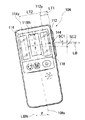
以下、本発明の実施の形態を図面に沿って説明する。図2に示すように、基準照射光として、例えば、所定の垂直軸線を中心に水平なレーザービームLBを回転させて基準水平面を設定するための光源であるレーザー装置102を設置する。レーザービームLBの到達する領域内の例えば壁(図示せず)上に、基準照射光検出装置104を配置する。LLは壁上のレーザービームLBの照射線を示し、DLは照射線LLから所定量ずらしたところの設定したい基準線を示す。基準照射光検出装置104は、図1に示すように、レーザービームLBを検出する方向に垂直に配置した第1受光部112及び第2受光部114と、検出したレーザービームLBの基準位置に対するシフト方向を示す表示部118とを有する。表示部118は、例えば、液晶パネル又はLEDにより構成されている。
【0010】
第1受光部112及び第2受光部114は、例えば、CCDにより構成されており、各々が上下方向に配列された複数の受光部分を有する。レーザー装置からのレーザービームLBが一方の受光部、例えば、第1受光部112の受光部分のうちの中間を走査するとき基準位置となり、表示部118の基準位置表示部分124が表示される。レーザービームLBが第1受光部112の上半分を走査する場合には、本体130を上方に移動し基準位置となるように、表示部118の上向き表示部分122が表示される。同様に、レーザービームLBが第1受光部112の下半分を走査する場合には、本体130を下方に移動し基準位置となるように、表示部118の下向き表示部分120が表示される。第1受光部112及び第2受光部114をCCD等の位置センサーや、特殊形状の受光素子等によって形成した場合には、より高精度な基準位置の検出が可能である。この場合は受光部の所定位置を基準位置と定めることで、受光部の基準位置に対するレーザービームLBの走査位置が決定される。
【0011】
基準照射光検出装置104は、図1に示すように、電源スイッチ150、検出精度調整スイッチ152、ブザー音量調整スイッチ154、及びブザー156を備える。
電源スイッチ150、検出精度調整スイッチ152、警告ブザー音量調整スイッチ154をメンブレンスイッチで構成するのがよい。
電源スイッチ150は、最初に押すと電源が入り、次に押すと電源が切れ、次に押すと再び電源が入るように構成されている。
検出精度調整スイッチ152は、最初に押すと高い検出精度に設定され、次に押すと低い検出精度に設定され、次に押すと再び高い検出精度に設定されるように構成されている。
【0012】
警告ブザー音量調整スイッチ154は、最初に押すと大きい音量に設定され、次に押すと中ぐらいの音量に設定され、次に押すと小さい音量に設定され、更に押すと再び大きい音量に設定されるように構成されている。
これらのスイッチを、ラバースイッチや、回転スイッチで構成してもよい。
指標144が、本体130の片側に基準位置表示部分124に対応した位置で設けられている。2つの指標を本体の両側に設けてもよい。
上述した構成の基準照射光検出装置104は、この本体130を壁(図示せず)上で上下移動させて、レーザービームLBが受光部112の基準位置(図示せず)に合致するようにする。レーザービームLBが受光部112の基準位置より上方にある時は上向き表示122が表示され本体130を上方へ移動させることを指示し、レーザービームLBが受光部112の基準位置より下方にある時は下向き表示120が表示されて本体130を下方へ移動させることを指示し、レーザービームLBが受光部112の基準位置に合致すると基準位置表示部分124が表示されて本体130の位置調整が完了したことを表示する。引き続いて、指標144を利用して壁上に罫書き等を行う。
【0013】
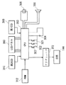
図3を参照すると、レーザー装置102は、基準照射光であるレーザー光を発光する光源部172と、光源部172の作動を制御する発光制御回路174と、レーザー光を収束させて光束を発する投光光学系176と、レーザー光の光束を回転させる光束回転手段即ち光束回転部材178とを備える。光源部172の発光したレーザー光は投光光学系176を通り、光束回転部材178により回転されて、レーザー光LBとして基準照射光検出装置104の第1受光部112及び第2受光部114に向かって、一定の回転速度で照射される。
基準照射光検出装置104は、レーザー光LBを受光する第1受光部112及び第2受光部114と、受光したレーザー光LBの状態を検出する受光状態検出回路210と、レーザー光LBの検出結果を表示する表示部118とを備える。
【0014】
表示部118は、受光したレーザー光LBの状態に対応して、基準位置表示部分124、上向き表示部分122又は下向き表示部分120のいずれかを表示する。表示部118を液晶パネル又はLEDで構成するのがよい。
基準照射光検出装置104は更に、第1受光部112と第2受光部114との間の距離を記憶する受光部間距離記憶回路240と、受光部間距離記憶回路240の記憶している第1受光部112と第2受光部114との間の距離の情報を用いて、第1受光部112及び第2受光部114の出力する受光結果信号に基づいて基準照射光検出装置104の傾きを演算する傾き演算回路244とを備える。表示部118は、傾き演算回路244の出力する出力信号に基づいて基準照射光検出装置104の傾きに関する情報を出力する傾き情報出力手段をも構成する。
【0015】
基準照射光検出装置104は更に、傾き演算回路244の出力する出力信号に基づいてブザーを駆動させる信号を出力するブザー駆動回路224と、ブザー駆動回路224の出力する出力信号に基づいて基準照射光検出装置104の傾きに関する警告信号を発生させる警告手段を構成するブザー156とを有する。
基準照射光検出装置104は更に、傾き演算回路244の出力する出力信号に基づいて指標を移動させる信号を出力する指標駆動回路250と、指標駆動回路250の出力する出力信号に基づいて指標144を移動させる指標駆動部材252と、指標144とを有する。
次に、本発明の基準照射光検出装置の具体的な構成と作動について説明する。
図4を参照すると、本発明の基準照射光検出装置は、電池等の電源304と、水晶振動子等の源振306と、レーザー光を受光する第1CCD308及び第2CCD310と、処理プログラムを記憶しかつ第1CCD308と第2CCD310との間の距離に関する情報を記憶しているROM312と、基準照射光検出装置の作動を制御するための1つ以上のスイッチ321〜323と、ROM312に記憶されている処理プログラムを動作させ、ROM312に記憶してあるデータを用いて、計数処理、演算処理及び比較処理を行うCPU350と、警告を発するブザー156又はスピーカ356(図には356を表示してある)と、演算結果などを表示するLCDパネル360とを備えている。
【0016】
電源304はリチウム電池又は銀電池を用いるのがよい。LCDパネル360の代わりに、蛍光管、LED等を用いてもよい。レーザー光を受光する素子は、PSDであってもよいし、或いは、縦にPDを配列して、基準照射光が横切る位置を検出できるようにしたセンサーであってもよい。スイッチ321〜323は、電源スイッチ150、検出精度調整スイッチ152、警告ブザー音量調整スイッチ154にそれぞれ対応する。本発明の基準照射光検出装置は更に、CPU350の指令に基づいて指標140を移動させるアクチュエータ372を有する。このアクチュエータ372をリニアモータを用いて構成するのがよい。
【0017】
なお、2つの指標を有する構成では、2つのアクチュエータを用意して、それぞれのアクチュエータにより指標を独立に移動させてもよいし、或いは、1つのアクチュエータだけを用いるように構成して、このアクチュエータにより2つの指標を同時に移動させるように構成してもよい。
次に、本発明の基準照射光検出装置104の作用について説明する。
電源スイッチ150をオンさせて基準照射光検出装置を動作状態にする。
レーザー装置102が照射するレーザー光LBは、回転数が一定に維持されており、ビーム径も一定であるように調整されている。なお、ビーム径が拡がり角を持つことを考慮に含めることもできる。第1受光部112及び第2受光部114のレーザー光LBの回転方向に対する幅も決まっている。
【0018】
図5を参照すると、基準照射光検出装置104の中心軸線104yが、基準照射光であるレーザー光LBの照射軌跡の法線LBNに対してθの傾きをもつときには、指標144がレーザー光LBからずれてしまう。
この場合に、第1受光部112の長手方向中心軸線112yと第2受光部114の長手方向中心軸線114yとの間の距離をLTとする。レーザー光LBの照射軌跡と、第1受光部112の長手方向中心112Cとの間の距離をST1とし、レーザー光LBの照射軌跡と、第2受光部114の長手方向中心114Cとの間の距離をST2とする。
距離をLTはROM312に記憶されている。また、距離ST1及びST2は、第1受光部112を構成する第1CCD380及び第2受光部114を構成する第2CCD310の出力する出力信号によりCPU350によって演算することができる。
【0019】
CPU350に内蔵されている傾き演算回路244は、ROM312が記憶しているLTの情報を入力し、第1CCD380の出力信号及び第2CCD310の出力信号に基づいて、基準照射光検出装置104の傾きを演算する。
この演算は、
θ = arctan ((ST1+ST2)/LT) ・・・(式1)
により行うことができる。
この(式1)もROM312に記憶されている。
傾きの演算結果は、表示部118で表示することができる。この表示は、傾きの方向又は符号と、傾きの角度により行うのがよい。
次に、指標の位置の補正の作動について説明する。
【0020】
第1受光部112の長手方向中心軸線112yから指標144までの距離をLT1とすると、指標144がレーザー光LBから上方にずれる量SC1は、
SC1 = LT1 × tanθ ・・・(式1)
である。
また、第2受光部114の長手方向中心軸線114yから指標144までの距離をLT2とすると、指標144がレーザー光LBから上方にずれる量SC2は、
SC2 = LT2 × tanθ ・・・(式2)
である。
傾き演算回路244は、基準照射光検出装置104の傾きθを演算するとともに、演算した結果の傾きθを用いてずれ量SC1又はSC2を演算する。傾きの値θとずれ量SC1又はSC2を表示部118で表示するように構成することができる。
【0021】
指標駆動回路230は指標を移動させるための指標駆動信号を指標駆動部材であるアクチュエータ372に出力する。これらのアクチュエータ372を作動させるための移動量を計算するための計算式はROM310に記憶されており、上記の演算はCPU350により行われる。
その結果、アクチュエータ372が作動して指標144を上方へSC1又はSC2だけ移動させる。
また、傾き演算回路222が演算した基準照射光検出装置104の傾きの補正演算結果は表示部118に表示される。表示の内容は、例えば、図6に示すように、基準照射光検出装置104の傾きを無くす方向を矢印118Rで示すことによって表示される。
【0022】
また、傾き演算回路222が演算した基準照射光検出装置104の傾きの補正演算結果はブザー駆動回路224に入力され、ブザー駆動回路224は傾きの補正演算結果に対応したブザー駆動信号を出力してブザー156により警告音を発生させる。例えば、基準照射光検出装置104の傾きの方向及び傾き量に対応して、警告音の音質、周波数、音量等を変化させる。変形例として、CPU350に音声合成回路を内蔵して、ブザー156の代わりにスピーカ356を用いて、基準照射光検出装置104の傾きの方向及び量を音声により指示することもできる。
また、SC1とSC2のずれ量から受光素子の基準位置をずらし、レーザー光LBと指標が一致するように、表示部に指示してもよい。
【0023】
また、図7に示すように、基準照射光LBSが水平線HZに対して傾きθを持つ場合がある。この場合には、第1指標140は上方にSH1だけずれており、第2指標142は下方にSH2だけずれている。
従って、図8に示すように、基準照射光検出装置104の中心軸線104yを垂直線VTに対して角度θとなるように基準照射光検出装置104を回転して位置決めしなければならない。
この場合には、基準照射光検出装置104の傾きを演算して、表示部118により、傾きの方向を矢印で表示し、傾きの量を数字で表示する。使用者はこの表示の値が0となり、方向を示す矢印が両方向を指示するように基準照射光検出装置104を回転させる。
【0024】
基準照射光検出装置104をこのような用途に用いる場合には、基準照射光検出装置104に勾配モード設定スイッチ500を設け、基準照射光検出装置104が勾配モードに設定されているときには、基準照射光検出装置104の傾きを表示し、或いは、基準照射光検出装置104の傾きの有無をブザー156により報知するように構成するのがよい。
【0025】
【発明の効果】
本発明によれば、下記の効果を有する。
(1)基準照射光検出装置の傾きを2つの受光部により検出して、その結果を表示部で表示することができる。
(2)基準照射光検出装置の傾きを2つの受光部により検出して、その結果を音により警告することができる。
(3)基準照射光を検出するための作業の効率を高くして、また、作業ミスの発生する可能性を低くすることができる。
【図面の簡単な説明】
【図1】 本発明の基準照射光検出装置の実施の形態を示す正面図である。
【図2】本発明の基準照射光検出装置がレーザー装置の照射する基準照射光を入射している状態を示す概略説明図である。
【図3】レーザー装置と、本発明の基準照射光検出装置の実施の形態を示すブロック図である。
【図4】本発明の基準照射光検出装置の具体的な構成を示すブロック図である。
【図5】傾きの検出の原理を説明するための、本発明の基準照射光検出装置の実施の形態を示す正面図である。
【図6】指標のずれを説明するための、本発明の基準照射光検出装置の実施の形態を示す正面図である。
【図7】基準照射光が傾いている場合における指標のずれを説明するための、基準照射光検出装置の実施の形態を示す正面図である。
【図8】基準照射光が傾いている場合において、その基準照射光に合わせた状態の基準照射光検出装置の実施の形態を示す正面図である。
【符号の説明】
102 レーザー装置
104 基準照射光検出装置
112 第1受光部
114 第2受光部
118 表示部
130 本体
120 下向き表示部分
122 上向き表示部分
124 基準位置表示部分
144 指標
150 電源スイッチ
152 検出精度調整スイッチ
154 ブザー音量調整スイッチ
156 ブザー
224 ブザー駆動回路
240 受光部間距離記憶回路
244 傾き演算回路
250 指標駆動回路
252 指標駆動部材
304 電源
306 源振
308 第1CCD
310 第2CCD
312 ROM
321〜323 スイッチ
350 CPU
356 スピーカ
360 LCDパネル[0001]
[Field of the Invention]
The present invention relates to a reference irradiation light detection device that detects reference irradiation light emitted from a light source.
[0002]
[Prior art]
When the reference irradiation light is detected by the reference irradiation light detection device, if the reference irradiation light detection device has an inclination, the position of the reference irradiation light is due to the distance between the light receiving unit of the reference irradiation light detection device and the index. In some cases, the position of the indicator is displaced. For this reason, conventionally, a bubble tube for an operator to confirm the inclination of the reference irradiation light detection device with the naked eye is arranged in the reference irradiation light detection device, and the reference irradiation light is detected based on the position of the bubble in the bubble tube. The inclination of the device was confirmed.
[0003]
[Problems to be solved by the invention]
In the above-described prior art, the efficiency of the operation for detecting the reference irradiation light is deteriorated, and the possibility of an operation error is increased.
[0004]
OBJECT OF THE INVENTION
In the reference irradiation light detection apparatus, the inclination of the apparatus is not visually confirmed using a bubble tube, but the inclination is detected and displayed by two light receiving units and / or the inclination is detected by sound. It is configured to warn, and it is an object to increase the efficiency of the operation for detecting the reference irradiation light and to reduce the possibility of an operation error.
It is another object of the present invention to provide a reference irradiation light detection device that can automatically correct a measurement error that occurs when the reference irradiation light detection device is tilted.
[0005]
[Means for solving the problems]
The reference irradiation light detection device of the present invention is provided with a first light receiving portion and a second light receiving portion which are provided on the main body so as to be spaced apart from each other and perpendicular to the direction in which the reference irradiation light is detected. And a light receiving state detecting means for detecting a light receiving state of the reference irradiation light based on an output signal output from at least one of the first light receiving unit and the second light receiving unit, and the reference irradiation light includes the first light receiving unit. In order to scan the reference irradiation light in the vertical direction, the light receiving state is scanned when one of the light receiving portions of the light receiving portion and the second light receiving portion is scanned. And a display unit that displays a direction in which the detector main body should be moved based on an output signal output from the detection means, and the display unit is disposed on the main body. In the reference irradiation light detection device of the present invention, the distance between the light receiving parts storing the distance between the first light receiving part and the second light receiving part and the distance storing means between the light receiving parts are stored. and it has the first light receiving portion and the information on the distance between the second light receiving portion, the first based on a light receiving unit and the output signal output of the second light receiving portion, the inclination state of the reference beam detector Is provided on both sides or one side of the main body, and is output from the tilt calculating means. And two or one index that is moved so as to coincide with the scanning position of the reference irradiation light based on the output signal.
[0006]
With this configuration, the inclination of the reference irradiation light detection device can be detected by the two light receiving units, the result can be displayed on the display unit, and / or the inclination can be warned by sound . Therefore, the efficiency of the operation for detecting the reference irradiation light can be increased, and the possibility of an operation error occurring can be reduced .
[0007]
Moreover, in the reference | standard irradiation light detection apparatus of this invention, it is preferable that an inclination information output means has a warning means which generate | occur | produces a warning signal. With this configuration, the inclination of the reference irradiation light detection device can be warned by sound.
[0008]
With this configuration, the inclination of the reference irradiation light detection device can be automatically corrected.
[0009]
DETAILED DESCRIPTION OF THE INVENTION
Hereinafter, embodiments of the present invention will be described with reference to the drawings. As shown in FIG. 2, as the reference irradiation light, for example, a
[0010]
The first
[0011]
As shown in FIG. 1, the reference irradiation
The
The
The detection
[0012]
The warning buzzer
These switches may be composed of rubber switches or rotary switches.
An
The reference irradiation
[0013]
Referring to FIG. 3, the
The reference irradiation
[0014]
The
The reference irradiation
[0015]
The reference irradiation
The reference irradiation
Next, a specific configuration and operation of the reference irradiation light detection device of the present invention will be described.
Referring to FIG. 4, the reference irradiation light detection apparatus of the present invention stores a
[0016]
The
[0017]
In a configuration having two indexes, two actuators may be prepared, and the indexes may be moved independently by each actuator, or only one actuator may be used, and this actuator may be used. You may comprise so that two parameter | indexes may be moved simultaneously.
Next, the operation of the reference irradiation
The
The laser beam LB irradiated by the
[0018]
Referring to FIG. 5, when the
In this case, let LT be the distance between the
The distance LT is stored in the
[0019]
The
This operation is
θ = arctan ((ST1 + ST2) / LT) (Expression 1)
Can be performed.
This (Equation 1) is also stored in the
The calculation result of the tilt can be displayed on the
Next, the operation for correcting the position of the index will be described.
[0020]
When the distance from the
SC1 = LT1 × tan θ (Expression 1)
It is.
Further, when the distance from the
SC2 = LT2 × tan θ (Expression 2)
It is.
The
[0021]
The index driving circuit 230 outputs an index driving signal for moving the index to the
As a result, the
Further, the tilt correction calculation result of the reference irradiation
[0022]
The inclination correction calculation result of the reference irradiation
Further, the display unit may be instructed so that the reference position of the light receiving element is shifted from the shift amount of SC1 and SC2, and the laser beam LB and the index coincide.
[0023]
Further, as shown in FIG. 7, the reference irradiation light LBS may have an inclination θ with respect to the horizontal line HZ. In this case, the
Therefore, as shown in FIG. 8, the reference irradiation
In this case, the inclination of the reference irradiation
[0024]
When the reference irradiation
[0025]
【The invention's effect】
The present invention has the following effects.
(1) The inclination of the reference irradiation light detection device can be detected by the two light receiving units, and the result can be displayed on the display unit.
(2) The inclination of the reference irradiation light detection device can be detected by the two light receiving units, and the result can be warned by sound.
(3) The efficiency of work for detecting the reference irradiation light can be increased, and the possibility of work mistakes can be reduced.
[Brief description of the drawings]
FIG. 1 is a front view showing an embodiment of a reference irradiation light detection device of the present invention.
FIG. 2 is a schematic explanatory diagram showing a state in which the reference irradiation light detection apparatus of the present invention is incident with reference irradiation light emitted from a laser device.
FIG. 3 is a block diagram showing an embodiment of a laser device and a reference irradiation light detection device of the present invention.
FIG. 4 is a block diagram showing a specific configuration of the reference irradiation light detection apparatus of the present invention.
FIG. 5 is a front view showing an embodiment of the reference irradiation light detection apparatus of the present invention for explaining the principle of inclination detection.
FIG. 6 is a front view showing an embodiment of a reference irradiation light detection apparatus of the present invention for explaining a deviation of an index.
FIG. 7 is a front view showing an embodiment of a reference irradiation light detection device for explaining an index shift when the reference irradiation light is inclined.
FIG. 8 is a front view showing an embodiment of the reference irradiation light detection device in a state matched with the reference irradiation light when the reference irradiation light is tilted.
[Explanation of symbols]
102
310 Second CCD
312 ROM
321-323
Claims (2)
本体と、
互いに間隔を隔てて設けられ、かつ、基準照射光を検出する方向に垂直になるように前記本体に配置した第1受光部及び第2受光部と、
前記第1受光部と前記第2受光部の少なくとも一方の出力する出力信号に基づいて前記基準照射光の受光状態を検出する受光状態検出手段と、
前記基準照射光が、前記第1受光部及び前記第2受光部のうちの一方の受光部を走査するときに、上下方向における前記一方の受光部の基準とする位置を前記基準照射光が走査するようにするために、前記受光状態検出手段が出力する出力信号に基づいて前記検出器本体を移動させるべき方向を表示する表示部とを備え、該表示部は前記本体に配置されており、
さらに、前記第1受光部と前記第2受光部との間の距離を記憶している受光部間距離記憶手段と、
受光部間距離記憶手段の記憶している前記第1受光部と前記第2受光部との間の距離に関する情報と、前記第1受光部及び前記第2受光部の出力する出力信号に基づいて、基準照射光検出装置の傾き状態を演算する傾き演算手段と、
前記傾き演算手段が出力する出力信号に基づいて傾きに関する情報を出力する傾き情報出力手段と、
前記本体の両側又は片側に設けられ、かつ、前記傾き演算手段が出力する出力信号に基づいて、前記基準照射光が走査する位置に一致するように移動させられる2個又は1個の指標と、
を備えることを特徴とする基準照射光検出装置。A reference irradiation light detection device for detecting reference irradiation light emitted from a light source,
The body,
A first light receiving unit and a second light receiving unit that are provided at a distance from each other and arranged in the main body so as to be perpendicular to a direction in which the reference irradiation light is detected;
A light receiving state detecting means for detecting a light receiving state of the reference irradiation light based on an output signal output from at least one of the first light receiving unit and the second light receiving unit;
When the reference irradiation light scans one of the first light receiving unit and the second light receiving unit, the reference irradiation light scans a position that is the reference of the one light receiving unit in the vertical direction. In order to do so, it comprises a display unit for displaying the direction in which the detector main body should be moved based on the output signal output by the light receiving state detecting means, and the display unit is disposed on the main body,
Furthermore, a distance storage unit between the light receiving units that stores a distance between the first light receiving unit and the second light receiving unit;
Based on the distance information about the output signal output from the first light receiving portion and the second light receiving portion between said first light receiving portion for storing the second light receiving portion of the distance memory unit between the light receiving portion Tilt calculating means for calculating the tilt state of the reference irradiation light detection device;
Inclination information output means for outputting information on inclination based on an output signal output by the inclination calculation means ;
Two or one index that is provided on both sides or one side of the main body and that is moved so as to coincide with the scanning position of the reference irradiation light, based on an output signal output by the tilt calculation means;
Reference beam detecting apparatus comprising: a.
Priority Applications (1)
| Application Number | Priority Date | Filing Date | Title |
|---|---|---|---|
| JP27753297A JP3802204B2 (en) | 1997-10-09 | 1997-10-09 | Reference irradiation light detector |
Applications Claiming Priority (1)
| Application Number | Priority Date | Filing Date | Title |
|---|---|---|---|
| JP27753297A JP3802204B2 (en) | 1997-10-09 | 1997-10-09 | Reference irradiation light detector |
Publications (2)
| Publication Number | Publication Date |
|---|---|
| JPH11118488A JPH11118488A (en) | 1999-04-30 |
| JP3802204B2 true JP3802204B2 (en) | 2006-07-26 |
Family
ID=17584884
Family Applications (1)
| Application Number | Title | Priority Date | Filing Date |
|---|---|---|---|
| JP27753297A Expired - Fee Related JP3802204B2 (en) | 1997-10-09 | 1997-10-09 | Reference irradiation light detector |
Country Status (1)
| Country | Link |
|---|---|
| JP (1) | JP3802204B2 (en) |
Families Citing this family (2)
| Publication number | Priority date | Publication date | Assignee | Title |
|---|---|---|---|---|
| JP6071844B2 (en) * | 2013-10-31 | 2017-02-01 | 株式会社錢高組 | Confirmation device for confirming displacement of wall and confirmation method thereof |
| KR102139248B1 (en) * | 2019-02-26 | 2020-07-29 | (주)인천측기 | apparatus and system for inspecting of horizontal and vertical line |
-
1997
- 1997-10-09 JP JP27753297A patent/JP3802204B2/en not_active Expired - Fee Related
Also Published As
| Publication number | Publication date |
|---|---|
| JPH11118488A (en) | 1999-04-30 |
Similar Documents
| Publication | Publication Date | Title |
|---|---|---|
| JP5796998B2 (en) | Survey point indicating device and survey system | |
| JP3731021B2 (en) | Position detection surveying instrument | |
| JP4180718B2 (en) | Rotating laser device | |
| US5216480A (en) | Surveying instrument | |
| JP2000171252A (en) | Rotary laser device and light receiving device | |
| JP2000193454A (en) | Rotating laser device | |
| JPH09257476A (en) | Laser irradiation equipment and target equipment | |
| JP2004093275A (en) | Angle detection device and projector having the same | |
| JP2005522684A (en) | Distance measuring device | |
| JPH11514093A (en) | Alignment error measuring device for two shafts arranged in front and behind | |
| US6616283B1 (en) | Projector | |
| GB2262997A (en) | Robot origin return system | |
| JP3802204B2 (en) | Reference irradiation light detector | |
| JP4152504B2 (en) | Reference irradiation light detector | |
| JP2019106942A (en) | Mower automatic travel system | |
| JPH11108662A (en) | Laser survey instrument | |
| JP3802203B2 (en) | Reference irradiation light detector | |
| JP3790023B2 (en) | Construction height display device and construction height setting device | |
| JP3937268B2 (en) | Laser equipment | |
| JP2001074457A (en) | Laser surveying instrument | |
| US6151106A (en) | Laser irradiation system | |
| JP4052908B2 (en) | Optical coordinate input system | |
| JP2696240B2 (en) | Surveying equipment | |
| EP2957994B1 (en) | Optical input device | |
| JP3615846B2 (en) | Surveying instrument |
Legal Events
| Date | Code | Title | Description |
|---|---|---|---|
| A521 | Written amendment |
Free format text: JAPANESE INTERMEDIATE CODE: A523 Effective date: 20040820 |
|
| A621 | Written request for application examination |
Free format text: JAPANESE INTERMEDIATE CODE: A621 Effective date: 20040820 |
|
| A977 | Report on retrieval |
Free format text: JAPANESE INTERMEDIATE CODE: A971007 Effective date: 20051007 |
|
| A131 | Notification of reasons for refusal |
Free format text: JAPANESE INTERMEDIATE CODE: A131 Effective date: 20051017 |
|
| A521 | Written amendment |
Free format text: JAPANESE INTERMEDIATE CODE: A523 Effective date: 20051214 |
|
| A131 | Notification of reasons for refusal |
Free format text: JAPANESE INTERMEDIATE CODE: A131 Effective date: 20060116 |
|
| A521 | Written amendment |
Free format text: JAPANESE INTERMEDIATE CODE: A523 Effective date: 20060317 |
|
| TRDD | Decision of grant or rejection written | ||
| A01 | Written decision to grant a patent or to grant a registration (utility model) |
Free format text: JAPANESE INTERMEDIATE CODE: A01 Effective date: 20060424 |
|
| A61 | First payment of annual fees (during grant procedure) |
Free format text: JAPANESE INTERMEDIATE CODE: A61 Effective date: 20060427 |
|
| R150 | Certificate of patent or registration of utility model |
Free format text: JAPANESE INTERMEDIATE CODE: R150 |
|
| FPAY | Renewal fee payment (event date is renewal date of database) |
Free format text: PAYMENT UNTIL: 20090512 Year of fee payment: 3 |
|
| FPAY | Renewal fee payment (event date is renewal date of database) |
Free format text: PAYMENT UNTIL: 20100512 Year of fee payment: 4 |
|
| FPAY | Renewal fee payment (event date is renewal date of database) |
Free format text: PAYMENT UNTIL: 20110512 Year of fee payment: 5 |
|
| LAPS | Cancellation because of no payment of annual fees |