JP3801774B2 - Positioning device - Google Patents
Positioning device Download PDFInfo
- Publication number
- JP3801774B2 JP3801774B2 JP08121398A JP8121398A JP3801774B2 JP 3801774 B2 JP3801774 B2 JP 3801774B2 JP 08121398 A JP08121398 A JP 08121398A JP 8121398 A JP8121398 A JP 8121398A JP 3801774 B2 JP3801774 B2 JP 3801774B2
- Authority
- JP
- Japan
- Prior art keywords
- satellite
- signal
- phase difference
- carrier phase
- positioning
- Prior art date
- Legal status (The legal status is an assumption and is not a legal conclusion. Google has not performed a legal analysis and makes no representation as to the accuracy of the status listed.)
- Expired - Fee Related
Links
Images
Landscapes
- Position Fixing By Use Of Radio Waves (AREA)
Description
【0001】
【発明の属する技術分野】
本発明は、主としてmm〜cmの測位精度を必要とする測量や土木工事等の分野で適用されると共に、全地球的衛星航法システム(Global Navigation Satellite System/以下、GNSSとする)衛星のうちの移動衛星であるGLONASS衛星を用いた測位装置に関する。
【0002】
【従来の技術】
近年、既に普及しているGPS(Global Positioning System)衛星を用いた高精度な測位装置が開発されている。このGPS衛星を用いた測位装置は、正確な位置が得られることにより、主にカーナビゲーションの分野で広く普及しているが、これ以外にもキャリアー周波数の位相(キャリア・フェーズと呼ばれる)を用いた干渉測位と呼ばれる方法を適用した場合にはmm〜cmの高精度が得られるため、こうした仕様の測位装置は測量や土木工事等の分野で必要とされる測位が可能になるため、急速に普及され始めている。
【0003】
干渉測位は、2つの地点として位置の分かっている点(既知点と呼ばれる)と位置を測定しようとしている点(未知点と呼ばれる)との距離(基線と呼ばれる)を例えばX,Y,Zの3次元的にmm〜cmの高精度で測定するもので、既知点及び未知点のそれぞれにGPS受信機を置き、同時に衛星のキャリア・フェーズを測定する。
【0004】
各衛星について未知点及び既知点におけるキャリア・フェーズの差を取り、更に或る基準衛星を適当に選んでそのキャリア・フェーズ差を基準として他の衛星のキャリア・フェーズ差との差である二重位相差を取る。この二重位相差は、既知点・未知点間及び異なる衛星間の差を取るため、受信機及び衛星に依存する測位誤差の殆どをキャンセルすることができ、しかも基線情報を含むため、これを解くことによって高精度な基線が得られる。因みに、このような二重位相差による測位方法に関する詳細な技術は、例えば日本測地学会編著:新訂版GPS−人工衛星による精密測位システム−、日本測量協会、1989年、第6章等の公知文献に記載されている。
【0005】
ところで、GPS衛星を用いた測位装置の場合、衛星を利用して測位精度を保証するために直接波を受信する必要があるが、例えば建物や樹木に挟まれた場所では一部の衛星からの信号が遮蔽されて測位に必要な衛星数からの受信を行うことができなくなることがあり、利用範囲に大きな制限を受けている。
【0006】
そこで、米国の運用するGPS衛星以外にもこれと類似するシステムとして知られるロシアが運用するGLONASS衛星が有るが、これらのGPS衛星及びGLONASS衛星の両方を用いれば受信可能な衛星数が増えて利用範囲が拡大する上、片方のシステムに障害が発生しても他方のシステムで測位できる可能性が増えることになる。こうした事情により、測量や土木工事等の分野で適用される測位装置では、GLONASS衛星及びGPS衛星の共用利用の検討が極めて盛んになっている。尚、GLONASS衛星はGPS衛星と類似したシステムで、GPS衛星と同様の方法で干渉測位を行うことができる。
【0007】
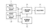
図2は、GLONASS衛星を用いた従来の測位装置の基本構成を示したブロック図である。この測位装置は、既知点でGLONASS衛星からの衛星信号に含まれるキャリア・フェーズを受信して既知点キャリア・フェーズ信号を出力する既知点キャリア・フェーズ受信部1と、未知点でGLONASS衛星からの衛星信号に含まれるキャリア・フェーズを受信して未知点キャリア・フェーズ信号を出力する未知点キャリア・フェーズ受信部2と、既知点キャリア・フェーズ信号並びに未知点キャリア・フェーズ信号に基づいて二重位相差を計算するときにGLONASS衛星のうちの既知点と未知点との両方で受信しているものから特定な対の基準衛星を選択した結果を衛星選択信号として出力する基準衛星選択部5と、既知点キャリア・フェーズ信号並びに未知点キャリア・フェーズ信号に基づいてLONASS衛星のうちの既知点と未知点との両方で受信しているものに関して衛星選択信号に示される基準衛星との間で二重位相差を計算して二重位相差信号を出力する二重位相差計算部3と、二重位相差信号に示される二重位相差を用いて基線を計算して基線信号を出力する測位計算部4とを備えている。
【0008】
このうち、既知点キャリア・フェーズ受信部1は、既知点キャリア・フェーズ信号を二重位相差計算部3及び基準衛星選択部5へ出力するもので、空中線(アンテナ)を含むGLONASS衛星用受信機そのもので構成しても良いし、既知点に設置したGLONASS衛星用受信機からの既知点キャリア・フェーズ信号を通信回線を経由して受信するタイプの通信用受信機で構成しても良い。
【0009】
同様に、未知点キャリア・フェーズ受信部2は、未知点キャリア・フェーズ信号を二重位相差計算部3及び基準衛星選択部5へ出力するもので、空中線を含むGLONASS衛星用受信機そのもので構成しても良いし、未知点に設置したGLONASS衛星用受信機からの未知点キャリア・フェーズ信号を通信回線を経由して受信するタイプの通信用受信機で構成しても良い。
【0010】
基準衛星選択部5は、GLONASS衛星のうちの既知点と未知点との両方で受信しているものから基準となるキャリア・フェーズ差を持つ特定な対の基準衛星を選択した結果を衛星選択信号として二重位相差計算部3へ出力するものであるが、通常基準衛星としては連続的に受信可能であり、しかもC/Nが比較的良くて安定した受信できるように、変更されることが少なく、且つその結果として変更に伴う計算の煩雑さが少ない高仰角衛星を用いるようにし、衛星選択信号のデータには衛星名を用いる。
【0011】
このような測位装置では、既知点キャリア・フェーズ受信部1及び未知点キャリア・フェーズ受信部2で受信した既知点及び未知点のキャリア・フェーズに基づいて基準衛星選択部5が基準衛星を選択した衛星選択信号を二重位相差計算部3へ送出し、二重位相差計算部3により既知点及び未知点のキャリア・フェーズに基づいて既知点と未知点との両方で受信しているGLONASS衛星に関して衛星選択信号に示される基準衛星との間で二重位相差を計算した結果を二重位相差信号として測位計算部4へ出力し、測位計算部4において二重位相差を用いて基線を計算した結果を基線信号として出力する。
【0012】
【発明が解決しようとする課題】
上述した測位装置の場合、機能上はGLONASS衛星を用いてもGPS衛星を用いた場合と同様に干渉測位を行うことができるが、一般にGPS衛星がCDMA(Code Division Multiple Access)方式であるのに対し、GLONASS衛星はFDMA(Frequency Division Multiple Access)方式であるため、受信機内部におけるフィルタ等の時間遅延により生じた時刻誤差が二重位相差を取ってもキャンセルできない程度の誤差となってしまうため、高精度測位を行う際の大きな問題となり、現状では測量や土木工事等の分野での適用が困難になっている。
【0013】
例えば公知文献として、D.Walsh and P.Daly:GPS and GLONASS Carrier Phase Ambiguity Resolution,Proceedings of the 9th International Technical Meeting of the Satellite Division of the Institute of Navigation,ION GPS−96,pp899〜907の記載によれば、GLONASSにおける誤差の要因の一つとして、fi を衛星名iのキャリア周波数[Hz],fj を衛星名jのキャリア周波数[Hz],dtB を未知点GLONASS衛星用受信機の時刻誤差[s],dtA を既知点GLONASS衛星用受信機の時刻誤差[s]とした場合、(fi −fj )(dtB −dtA )なる関係で示されるものがあり、これが極めて大きな影響を与えるとされている。因みに、GPSであれば全ての衛星のキャリア周波数は同じなので、衛星間キャリア周波数差fi −fj =0となり、このような誤差は生じない。
【0014】
又、他の公知文献として、S.A.Gourevitch,S.S.Novitsky and F.V.Diggelen:The GG24 Combined GPS+GLONASS Receiver,Proceedingsof the 9th International Technical Meeting of the Satellite Division ofthe Institute of Navigation,ION GPS−96,pp141〜145の記載によれば、dtB −dtA が10[ns],fi −fj =20[MHz]のときに3センチメートルの測位誤差を生ずることが開示されているが、これから解るように、mm〜cmの精度で測位しようとするときには3センチメートルの測位誤差は極めて大きな問題であるといえる。
【0015】
このような測位誤差を抑える方法の一つとして、フィルタ等の時間遅延の受信機間のばらつきを抑えること(特に温度特性を改善すること)が挙げられるが、実際には価格上の制約や大きさの制限がある上、温度特性の改善が技術的に困難であるため、実現化されていない。一部の特殊な観測用GLONASS衛星用受信機の研究開発では、価格を省みずに受信機のみならず空中線までを温度特性の制御を行って性能を改善する提案もなされているが、こうした構成では汎用化が見込まれない。
【0016】
そこで、別の方法としてGPS衛星及びGLONASS衛星の共用受信機において、GPS衛星とGLONASS衛星とを同等に扱わず、GLONASS衛星を軽視した処理を行ってGLONASS衛星による悪影響を軽減しているが、こうした場合にはGLONASS衛星からの受信を行うにも拘らず有効利用していない点が問題である。
【0017】
本発明は、このような問題点を解決すべくなされたもので、その技術的課題は、測位誤差を充分に抑制できて高精度な測位が可能なGLONASS衛星を用いた測位装置を提供することにある。
【0018】
【課題を解決するための手段】
本発明によれば、位置の分かっている既知点でGLONASS衛星からの衛星信号に含まれるキャリア・フェーズを受信して既知点キャリア・フェーズ信号を出力する既知点キャリア・フェーズ受信部と、位置を測定しようとしている未知点でGLONASS衛星からの衛星信号に含まれるキャリア・フェーズを受信して未知点キャリア・フェーズ信号を出力する未知点キャリア・フェーズ受信部と、既知点キャリア・フェーズ信号並びに未知点キャリア・フェーズ信号に基づいてGLONASS衛星のうちの既知点と未知点との両方で受信しているものから選択された特定な対の基準衛星との間で二重位相差を計算した結果を二重位相差信号として出力する二重位相差計算部と、二重位相差信号に示される二重位相差を用いて基線を計算する測位計算部とを備えた測位装置において、既知点キャリア・フェーズ信号並びに未知点キャリア・フェーズ信号に基づいて二重位相差を計算するときに特定な対の基準衛星を衛星間キャリア周波数差が小さくなるようにGLONASS衛星のうちの既知点と未知点との両方で受信しているものから該二重位相差毎に可変させて選択した結果を衛星対選択信号として二重位相差計算部へ出力する衛星対選択部を備えた測位装置が得られる。
【0019】
【発明の実施の形態】
以下に実施例を挙げ、本発明の測位装置について、図面を参照して詳細に説明する。
【0020】
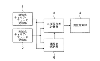
図1は、本発明の一実施例に係る測位装置の基本構成を示したブロック図である。この測位装置も、図2に示した従来装置と同様に、既知点でGLONASS衛星からの衛星信号に含まれるキャリア・フェーズを受信して既知点キャリア・フェーズ信号を出力する既知点キャリア・フェーズ受信部1と、位置を測定しようとしている未知点でGLONASS衛星からの衛星信号に含まれるキャリア・フェーズを受信して未知点キャリア・フェーズ信号を出力する未知点キャリア・フェーズ受信部2と、既知点キャリア・フェーズ信号並びに未知点キャリア・フェーズ信号に基づいてGLONASS衛星のうちの既知点と未知点との両方で受信しているものから選択された特定な対の基準衛星との間で二重位相差を計算した結果を二重位相差信号として出力する二重位相差計算部3と、二重位相差信号に示される二重位相差を用いて基線を計算する測位計算部4とを備えているが、ここでは図2に示した基準衛星選択部5に代え、特定な対の基準衛星を衛星間キャリア周波数差(即ち、上述したfi −fj )が小さくなるようにGLONASS衛星のうちの既知点と未知点との両方で受信しているものから二重位相差毎に可変させて選択した結果を衛星対選択信号として二重位相差計算部3へ出力する衛星対選択部6を備えている。
【0021】
即ち、ここでの衛星対選択部6は、基準衛星を二重位相差毎に変える機能を有している。具体的に云えば、既知点と未知点との両方で受信しているGLONASS衛星をキャリア周波数の小さい順に並べ、例えば最初の衛星対を1番目及び2番目の衛星,次の衛星対を2番目及び3番目の衛星という具合に順次衛星対を決め、それらの衛星対の衛星名を衛星対選択信号のデータとして二重位相差計算部3へ出力する。
【0022】
そこで、二重位相差計算部3では、既知点キャリア・フェーズ受信部1からの既知点キャリア・フェーズ信号と未知点キャリア・フェーズ受信部2からの未知点キャリア・フェーズ信号とに基づいて衛星対選択部6からの衛星対選択信号に示される衛星対である特定な対の基準衛星との間で二重位相差を計算し、その結果の二重位相差信号を測位計算部4へ出力する。この二重位相差信号は基線の情報を含むため、測位計算部4でこれを解くことにより高精度な基線の計算結果を示す基線信号が得られる。
【0023】
GLONASS衛星の場合、完成時は24個の衛星が運用されて平均8衛星の受信が可能である。8衛星が24衛星中から均等に受信できると仮定すれば、24衛星で20[MHz]の周波数差でなので、8衛星の隣り同士の周波数差は平均20/8=2.5[MHz]となる。20[MHz]で3センチメートルの測位誤差を生ずるとすれば、2.5[MHz]では3・2.5/20=0.4センチメートルとなり、測位誤差を従来の約1/10に抑えることができる。
【0024】
従って、この測位装置によりGLONASS衛星を用いて測位(基線の計算)を行えば、二重位相差計算部3において二重位相差計算時に用いられる特定な対の基準衛星を衛星対選択部6によって衛星間キャリア周波数差が小さくなるように二重位相差毎に変えて選択した上で二重位相差の計算が行われるため、測位計算部4で二重位相差を用いて基線を計算する際にキャリア周波数差により生ずる測位誤差を大幅に小さくできるため、結果としてmm〜cmの要求精度に対して充分に応えられるものとなる。
【0025】
尚、このような特定な対の基準衛星を二重位相差毎に変える機能は、従来装置における特定な対の基準衛星を選択する機能を二重位相差毎に変えて行うように変更すれば良いため、ソフトウェアの変更のみで簡単に済ませられ、これによる計算の複雑さも現在のパソコンに見られるようにIC技術の発達による高性能CPUの出現で問題無く対応することができる。
【0026】
【発明の効果】
以上に述べた通り、本発明のGLONASS衛星を用いた測位装置によれば、二重位相差計算時に用いられる特定な対の基準衛星を衛星間キャリア周波数差が小さくなるように二重位相差毎に変えて選択した上で測位(基線の計算)を行うようにしているので、キャリア周波数差により生ずる測位誤差を大幅に小さくすることができてmm〜cmの要求精度に対して充分に応えられ、GPS衛星を用いた場合と同程度の高測位精度を維持できるようになる。又、この特定な対の基準衛星を二重位相差毎に変える機能は、従来装置における特定な対の基準衛星を選択する機能を二重位相差毎に変えて行うようにソフトウェアによる変更のみで実施できるため、価格や装置の大きさ、或いは利用者への使用方法等に全く悪影響を与えずに具現できるという利点がある。この結果、この測位装置はその高精度な測位の性能から年間百万台に達しようとするカーナビゲーション程ではないといえ、従来に無く測量や土木工事等の分野への適用が有効になる他、こうした分野以外の様々な分野への普及も期待できる。特に受信環境が厳しくGPS衛星だけでは測位に必要な衛星数を受信できないような条件下でGLONASS衛星無しでは使用できないような場合に充分に効力を発揮できるため、こうした場合には極めて利用価値が高いものとなる。
【図面の簡単な説明】
【図1】本発明の一実施例に係る測位装置の基本構成を示したブロック図である。
【図2】従来の測位装置の基本構成を示したブロック図である。
【符号の説明】
1 既知点キャリア・フェーズ受信部
2 未知点キャリア・フェーズ受信部
3 二重位相差計算部
4 測位計算部
5 基準衛星選択部
6 衛星対選択部[0001]
BACKGROUND OF THE INVENTION
The present invention is mainly applied to fields such as surveying and civil engineering that require positioning accuracy of mm to cm, and is a global navigation satellite system (hereinafter referred to as GNSS) satellite. The present invention relates to a positioning apparatus using a GLONASS satellite which is a mobile satellite.
[0002]
[Prior art]
In recent years, a highly accurate positioning apparatus using a GPS (Global Positioning System) satellite that has already been widely used has been developed. Positioning devices using GPS satellites are widely used mainly in the field of car navigation because they can obtain accurate positions, but they also use the phase of the carrier frequency (called the carrier phase). When a method called interference positioning is applied, high accuracy of mm to cm can be obtained, so positioning devices with these specifications can perform positioning required in fields such as surveying and civil engineering. It is becoming popular.
[0003]
Interferometric positioning is the distance (called a base line) between a point whose position is known as two points (called a known point) and a point whose position is to be measured (called an unknown point), for example X, Y, Z This is a three-dimensional measurement with high accuracy of mm to cm. A GPS receiver is placed at each of the known and unknown points, and the carrier phase of the satellite is measured at the same time.
[0004]
The difference between the unknown point and the carrier phase at the known point is taken for each satellite, and a reference satellite is appropriately selected and the difference between the carrier phase difference of other satellites based on the carrier phase difference. Take the phase difference. This double phase difference is the difference between known and unknown points and between different satellites, so that most of the positioning errors depending on the receiver and satellite can be canceled, and the baseline information is included. By solving, a high-precision baseline can be obtained. Incidentally, the detailed technique regarding the positioning method based on such a double phase difference is, for example, known by the Geodetic Society of Japan: Newly revised version GPS-accurate positioning system using artificial satellites, Japan Surveying Association, 1989,
[0005]
By the way, in the case of a positioning device using a GPS satellite, it is necessary to directly receive a wave in order to guarantee positioning accuracy using the satellite. For example, in a place sandwiched between buildings or trees, Since the signal may be blocked and reception from the number of satellites necessary for positioning may not be possible, the usage range is greatly limited.
[0006]
Therefore, in addition to GPS satellites operated by the United States, there are GLONASS satellites operated by Russia known as a similar system. However, if both of these GPS satellites and GLONASS satellites are used, the number of receivable satellites increases. In addition to expanding the range, if one system fails, the possibility of positioning with the other system increases. Under such circumstances, in the positioning apparatus applied in the field of surveying, civil engineering work, etc., examination of the shared use of the GLONASS satellite and the GPS satellite is very active. The GLONASS satellite is a system similar to a GPS satellite, and can perform interference positioning in the same manner as the GPS satellite.
[0007]
FIG. 2 is a block diagram showing a basic configuration of a conventional positioning apparatus using a GLONASS satellite. The positioning device includes a known point carrier
[0008]
Among these, the known point carrier
[0009]
Similarly, the unknown point carrier
[0010]
The reference
[0011]
In such a positioning device, the reference
[0012]
[Problems to be solved by the invention]
In the case of the above-described positioning device, even if a GLONASS satellite is used in terms of function, interference positioning can be performed in the same manner as when using a GPS satellite. However, although the GPS satellite is generally a CDMA (Code Division Multiple Access) system. On the other hand, since the GLONASS satellite is a FDMA (Frequency Division Multiple Access) system, the time error caused by the time delay of the filter in the receiver becomes an error that cannot be canceled even if a double phase difference is taken. Therefore, it becomes a big problem when performing high-precision positioning, and it is difficult to apply it in fields such as surveying and civil engineering at present.
[0013]
For example, D. Walsh and P.M. Daly: GPS and GLONASS Carrier Phase Ambiguity Resolution, Proceedings of the 9th International Technical Meeting of the World of the 8th, and the 9th International Technical of the World of the 8th. , F i is the carrier frequency [Hz] of the satellite name i, f j is the carrier frequency [Hz] of the satellite name j, dt B is the time error [s] of the receiver for the unknown point GLONASS satellite, and dt A is the known point GLONASS. If the time error [s] of the satellite receiver, (f i -f j) ( dt B -dt a) becomes that shown by the relationship There has been that this gives a very big impact. Incidentally, since the carrier frequency of all satellites is the same in the case of GPS, the inter-satellite carrier frequency difference f i −f j = 0, and such an error does not occur.
[0014]
As another known document, S.A. A. Gourevich, S.M. S. Novitsky and F.M. V. Diggelen: The GG24 Combined GPS + GLONASS Receiver, Proceedingsof the 9th International Technical Meeting of the Satellite Division ofthe Institute of Navigation, ION GPS-96, according to the description of pp141~145, dt B -dt A is 10 [ns], f i Although it has been disclosed that a positioning error of 3 centimeters occurs when −f j = 20 [MHz], as will be understood from this, a positioning error of 3 centimeters is required when positioning with an accuracy of mm to cm. It can be said that it is a very big problem.
[0015]
One way to suppress such positioning errors is to suppress variations in time delay between receivers such as filters (especially to improve temperature characteristics). In addition, there is a limitation, and since it is technically difficult to improve temperature characteristics, it has not been realized. In the research and development of some special GLONASS satellite receivers for observation, proposals have been made to improve the performance by controlling the temperature characteristics of not only the receiver but also the antenna without saving the price. So generalization is not expected.
[0016]
Therefore, as a different method, the GPS satellite and the GLONASS satellite shared receiver do not treat the GPS satellite and the GLONASS satellite equally, and the GLONASS satellite is disregarded to reduce the adverse effects of the GLONASS satellite. In this case, there is a problem that it is not used effectively despite the reception from the GLONASS satellite.
[0017]
The present invention has been made to solve such problems, and a technical problem thereof is to provide a positioning device using a GLONASS satellite capable of sufficiently suppressing positioning errors and capable of highly accurate positioning. It is in.
[0018]
[Means for Solving the Problems]
According to the present invention, a known point carrier phase receiving unit that receives a carrier phase included in a satellite signal from a GLONASS satellite at a known point whose position is known and outputs a known point carrier phase signal; An unknown point carrier phase receiving unit for receiving the carrier phase included in the satellite signal from the GLONASS satellite at the unknown point to be measured and outputting the unknown point carrier phase signal, the known point carrier phase signal and the unknown point Based on the carrier phase signal, the result of calculating the double phase difference between a specific pair of reference satellites selected from those received at both known and unknown GLONASS satellites is calculated as two results. Calculate the baseline using the double phase difference calculation unit that outputs as a double phase difference signal and the double phase difference shown in the double phase difference signal. In a positioning device equipped with a positioning calculation unit, when calculating a double phase difference based on a known point carrier phase signal and an unknown point carrier phase signal, a specific pair of reference satellites has a small inter-satellite carrier frequency difference. As a result, the GLONASS satellites received from both known and unknown points are variably selected for each double phase difference and the result is output to the double phase difference calculation unit as a satellite pair selection signal. A positioning device including a satellite pair selection unit is obtained.
[0019]
DETAILED DESCRIPTION OF THE INVENTION
The positioning device of the present invention will be described in detail below with reference to the drawings by giving examples.
[0020]
FIG. 1 is a block diagram showing a basic configuration of a positioning apparatus according to an embodiment of the present invention. Similarly to the conventional device shown in FIG. 2, this positioning device also receives a carrier phase included in a satellite signal from a GLONASS satellite at a known point and outputs a known point carrier phase signal.
[0021]
In other words, the satellite
[0022]
Therefore, the double phase
[0023]
In the case of a GLONASS satellite, when completed, 24 satellites are operated and an average of 8 satellites can be received. Assuming that 8 satellites can be received evenly from 24 satellites, the frequency difference between the adjacent 20 satellites is 20/8 = 2.5 [MHz] because the 24 satellites have a frequency difference of 20 [MHz]. Become. If a positioning error of 3 centimeters occurs at 20 [MHz], 2.5.20 / 0.4 centimeters at 2.5 [MHz], and the positioning error is reduced to about 1/10 of the conventional one. be able to.
[0024]
Therefore, if positioning (baseline calculation) is performed using the GLONASS satellite by this positioning device, a specific pair of reference satellites used in the double phase difference calculation in the double phase
[0025]
It should be noted that the function of changing such a specific pair of reference satellites for each double phase difference can be changed by changing the function of selecting a specific pair of reference satellites in the conventional apparatus for each double phase difference. Since it is good, it can be done simply by changing the software, and the complexity of the calculation can be dealt with without any problems with the advent of high-performance CPUs due to the development of IC technology as seen in current personal computers.
[0026]
【The invention's effect】
As described above, according to the positioning apparatus using the GLONASS satellite of the present invention, a specific pair of reference satellites used in the calculation of the double phase difference is set for each double phase difference so that the inter-satellite carrier frequency difference becomes small. Since the positioning (baseline calculation) is performed after selection, the positioning error caused by the carrier frequency difference can be greatly reduced, and the required accuracy of mm to cm can be fully met. As a result, it is possible to maintain the same high positioning accuracy as when using a GPS satellite. The function of changing the specific pair of reference satellites for each double phase difference can be changed only by software so that the function of selecting the specific pair of reference satellites in the conventional apparatus is changed for each double phase difference. Since it can be implemented, there is an advantage that it can be implemented without adversely affecting the price, the size of the apparatus, or the usage method for the user. As a result, this positioning device is not as good as the car navigation system that will reach millions of cars annually because of its high-accuracy positioning performance, but it has become more effective than ever before in applications such as surveying and civil engineering. It can be expected to spread to various fields other than these fields. It is extremely useful in such cases, especially when the reception environment is harsh and GPS satellites alone cannot receive the number of satellites required for positioning and cannot be used without GLONASS satellites. It will be a thing.
[Brief description of the drawings]
FIG. 1 is a block diagram showing a basic configuration of a positioning apparatus according to an embodiment of the present invention.
FIG. 2 is a block diagram showing a basic configuration of a conventional positioning device.
[Explanation of symbols]
DESCRIPTION OF
Claims (1)
Priority Applications (1)
| Application Number | Priority Date | Filing Date | Title |
|---|---|---|---|
| JP08121398A JP3801774B2 (en) | 1998-03-27 | 1998-03-27 | Positioning device |
Applications Claiming Priority (1)
| Application Number | Priority Date | Filing Date | Title |
|---|---|---|---|
| JP08121398A JP3801774B2 (en) | 1998-03-27 | 1998-03-27 | Positioning device |
Publications (2)
| Publication Number | Publication Date |
|---|---|
| JPH11281726A JPH11281726A (en) | 1999-10-15 |
| JP3801774B2 true JP3801774B2 (en) | 2006-07-26 |
Family
ID=13740215
Family Applications (1)
| Application Number | Title | Priority Date | Filing Date |
|---|---|---|---|
| JP08121398A Expired - Fee Related JP3801774B2 (en) | 1998-03-27 | 1998-03-27 | Positioning device |
Country Status (1)
| Country | Link |
|---|---|
| JP (1) | JP3801774B2 (en) |
Families Citing this family (1)
| Publication number | Priority date | Publication date | Assignee | Title |
|---|---|---|---|---|
| CN116660959B (en) * | 2023-08-02 | 2023-09-26 | 银河航天(北京)网络技术有限公司 | Method, device and storage medium for double-difference positioning by utilizing target satellite |
-
1998
- 1998-03-27 JP JP08121398A patent/JP3801774B2/en not_active Expired - Fee Related
Also Published As
| Publication number | Publication date |
|---|---|
| JPH11281726A (en) | 1999-10-15 |
Similar Documents
| Publication | Publication Date | Title |
|---|---|---|
| CN101600970B (en) | Combine measurements and determine clock skew | |
| JP5050904B2 (en) | Current position positioning method and positioning device | |
| JP5109706B2 (en) | Positioning method and positioning device | |
| JP6069840B2 (en) | Moving speed calculation method and moving speed calculation device | |
| US20090267832A1 (en) | Systems and methods for dynamically determining position | |
| CN102162732A (en) | Method and system for calculating position | |
| JP2003518632A (en) | Method and apparatus for determining algebraic solutions to GPS ground hybrid positioning system equations | |
| JP5526492B2 (en) | Pseudo distance calculation method, positioning method, program, and positioning device | |
| JP7065277B2 (en) | Positioning method and positioning terminal | |
| US20190049594A1 (en) | Coordinate output method and coordinate output device | |
| US6567712B1 (en) | Method for determining the co-ordinates of a satellite | |
| WO2019003623A1 (en) | Positioning method and positioning terminal | |
| US20070250266A1 (en) | Information processing apparatus and GPS positioning method | |
| MX2008010827A (en) | Method and apparatus for code space search in a receiver. | |
| KR20050041794A (en) | Method for generating acquisition assistant information in assisted global positioning system | |
| JP2000193733A (en) | Positioning device and positioning method | |
| KR100721517B1 (en) | Apparatus and method for determining a position of mobile terminal equipment | |
| WO2018225421A1 (en) | Positioning method and positioning terminal | |
| CN111610543A (en) | Low-power-consumption processing method and device, positioning system and storage medium | |
| JP3801774B2 (en) | Positioning device | |
| CN101765201A (en) | Location aided method and location aided device using same | |
| CN102156276A (en) | Satellite signal tracking method, position calculating method, and position calculating device | |
| US20150091750A1 (en) | Filtering for global positioning system (gps) receivers | |
| RU2253128C1 (en) | Method for determination of object relative coordinates with survey to arbitrary point of space and system for its realization | |
| KR20030004643A (en) | Satellite Navigation System and Attitude Determination Method of Object using the same |
Legal Events
| Date | Code | Title | Description |
|---|---|---|---|
| A621 | Written request for application examination |
Free format text: JAPANESE INTERMEDIATE CODE: A621 Effective date: 20050127 |
|
| A977 | Report on retrieval |
Free format text: JAPANESE INTERMEDIATE CODE: A971007 Effective date: 20060406 |
|
| TRDD | Decision of grant or rejection written | ||
| A01 | Written decision to grant a patent or to grant a registration (utility model) |
Free format text: JAPANESE INTERMEDIATE CODE: A01 Effective date: 20060419 |
|
| A61 | First payment of annual fees (during grant procedure) |
Free format text: JAPANESE INTERMEDIATE CODE: A61 Effective date: 20060426 |
|
| R150 | Certificate of patent or registration of utility model |
Free format text: JAPANESE INTERMEDIATE CODE: R150 |
|
| LAPS | Cancellation because of no payment of annual fees |