JP3800733B2 - Vending machine product storage device - Google Patents
Vending machine product storage device Download PDFInfo
- Publication number
- JP3800733B2 JP3800733B2 JP16531197A JP16531197A JP3800733B2 JP 3800733 B2 JP3800733 B2 JP 3800733B2 JP 16531197 A JP16531197 A JP 16531197A JP 16531197 A JP16531197 A JP 16531197A JP 3800733 B2 JP3800733 B2 JP 3800733B2
- Authority
- JP
- Japan
- Prior art keywords
- product
- adapter
- passage
- vending machine
- storage device
- Prior art date
- Legal status (The legal status is an assumption and is not a legal conclusion. Google has not performed a legal analysis and makes no representation as to the accuracy of the status listed.)
- Expired - Fee Related
Links
Images


Description
【0001】
【発明の属する技術分野】
本発明は、商品通路内に多数の商品を前後方向に並べて収納し、販売時に1個の商品を商品通路の前側から払い出すタイプの自動販売機の商品収納装置に関する。
【0002】
【従来の技術】
この種の自動販売機の商品収納装置を、例えば特願平8−355374号ですでに提案している。図13に示すように、この商品収納装置50では、商品ラック51を中央の仕切壁54で仕切ることにより、左右2列の商品通路52が形成されている。仕切壁54の前端には、商品通路52の払出口を開閉する透明な開閉板55が設けられ、その後方にはプッシャ56が設けられていて、商品Sは、開閉板55とプッシャ56の間に挟持された状態で、各商品通路52内に多数、並んで収納される。
【0003】
開閉板55は、仕切壁54を貫通する駆動軸59の前端に固定され、駆動軸59は、販売時に、駆動機構(図示せず)によって回転駆動される。また、各商品通路52の前端にはフラッパ58が連設され、このフラッパ58は、連動機構(図示せず)を介して駆動軸59と連結されており、販売待機時には水平姿勢に支持されている。また、この商品収納装置50は、販売時に前から2番目の商品(次販商品)Sを保持する2つのホルダ57、57(1個のみ図示)を備えている。各ホルダ57は、折り曲げた板状のものであり、仕切壁54内に立設した支軸に後端部が回動自在に支持され、仕切壁54の開口から対応する商品通路52に出没可能になっていて、上記駆動機構によって駆動される。
【0004】
商品Sの販売時には、駆動機構が作動し、駆動軸59が所定方向に回転することで、まず、ホルダ57が、駆動軸59に一体に設けられたカム(図示せず)で押圧される、これにより、商品通路52に突出し、商品通路52の側壁52aとの間に、次販商品Sを挟持して、これを保持する。次いで、駆動59の回転に伴う開閉板55の回動によって、反対側の商品通路52が開放されるとともに、開放された商品通路52のフラッパ58が、連動機構による支持を解かれて前下がりに自由回動する。これにより、最前位の商品(販売商品)Sが自然落下によって商品通路52から払い出され、商品Sを1個ずつ払い出すことができる。
【0005】
【発明が解決しようとする課題】
しかし、上記の商品収納装置50は、特に商品Sが飲口側にキャップやつばを有する逆円錐台形のカップ形状商品である場合、商品Sの払出しを確実に行うという点で改善の余地がある。すなわち、商品収納装置50にこのようなカップ形状商品を収納した場合には、隣接する商品S、S間でキャップやつば同士が引っ掛かりやすいとともに、商品Sの重心が高いため、プッシャの押圧力で商品Sが前方に傾きやすい。特に、次販商品Sについては、払出動作時にホルダ20に挟持されるとともに、この場合、ホルダ20はその構造上、次販商品Sの下部に当接することから、前方に傾きやすく、販売商品Sに引っ掛かりやすい。
【0006】
そして、このような引っ掛かり現象が販売商品Sと次販商品Sの間に生じた場合には、上記の商品収納装置50で前述したような自然落下に依存した販売商品Sの払出動作を行っても、販売商品Sが次販商品Sによって商品通路52内に保持されてしまい、販売不良となるおそれがある。また、上記のように次販商品Sが傾けば、払出動作後に次の販売待機状態へ移行するための商品S全体の移動も円滑に行えないとともに、ディスプレイ効果も損われてしまう。
【0007】
本発明は、このような課題を解決するためになされたものであり、商品がカップ形状商品の場合でも、商品を確実に1個ずつ払い出すことができ、販売待機状態への移行を円滑に行えるとともに、ディスプレイ効果を向上させることができる自動販売機の商品収納装置を提供することを目的とする。
【0008】
【課題を解決するための手段】
この目的を達成するため、本発明の自動販売機の商品収納装置は、前端に払出口を有するとともに、多数の商品を前後方向に並べて収納する商品通路を形成した商品ラックと、商品通路の払出口を開放する開放位置と、閉鎖する閉鎖位置との間で回動可能で、販売時に開放位置に回動することにより販売商品を商品通路から払い出す開閉部材と、商品通路に収納された商品を前方に押圧するプッシャと、商品通路に突出する突出位置と、この商品通路から退避する退避位置との間で回動可能で、販売時に突出位置に回動することにより次販商品を保持するホルダと、開閉部材の開放位置への回動に連動して、販売商品を払出口側へ押圧することにより送り出す送出手段と、を備えていることを特徴としている。
【0009】
この自動販売機の商品収納装置によれば、販売待機状態では、開閉部材が、閉鎖位置に位置し、商品通路の払出口を閉鎖しており、商品は、この開閉部材とプッシャとの間に挟持された状態で、商品通路内に前後方向に並んで収納されている。また、ホルダは、退避位置に位置し、商品通路から退避している。商品の販売時には、まず、ホルダが、突出位置に回動して、商品通路に突出することにより、次販商品(前から2番目の商品)を保持する。次いで、開閉部材が、開放位置に回動して商品通路の払出口を開放する。また、この開閉部材の開放と連動して、送出手段が販売商品(最前位の商品)を払出口側に押圧することにより送り出すことによって、販売商品を商品ラックから払い出す。このように、本発明では、開閉部材の開放と連動して、送出手段が販売商品のみを払出口側に押圧することにより送り出すので、商品がカップ形状商品で、販売商品と次販商品の間にキャップなどによる引っ掛かりが生じている場合であっても、販売商品をホルダで保持された次販商品から強制的に引き離すことができ、したがって、販売商品を確実に払い出すことができる。
【0010】
さらに、本発明の自動販売機の商品収納装置は、商品通路が、仕切壁によって互いに仕切られた左右の商品通路で構成され、ホルダが、仕切壁に回動自在に取り付けられた左右のホルダで構成されるとともに、送出手段は、仕切壁の上面前端部に取り付けられたアダプタで構成され、このアダプタは、支軸を有し、仕切壁に取り付けられたベースと、このベースの支軸に鉛直軸線回りに回動自在にそれぞれ取り付けられ、各々が、支軸の前側の係止部と後ろ側の送出部を有する左右のアームと、これら左右のアームの係止部を近づき合う方向に付勢するばねと、を備え、左右のアームの係止部は、開閉部材が閉鎖位置にあるとき、ばねのばね力に抗して広がった状態で開閉部材に係止されるとともに、送出部は、係止部が広がった状態では商品通路から退避し、かつ係止部が狭まったときに商品通路に突出して販売商品を払出口側へ送り出すような形状を有することを特徴としている。
【0011】
この構成では、商品通路が左右2列で構成され、ホルダも両商品通路用に左右2つで構成されるとともに、送出手段は、商品通路を仕切る仕切壁の上面に取り付けたアダプタで構成されている。販売待機状態では、アダプタの一対の係止部が、ばねのばね力に抗して広がった状態で、閉鎖位置にある開閉部材に係止されており、これに伴い、アダプタの一対の送出部は、商品通路から退避している。商品の販売時には、開閉部材の開放位置への回動によって、アダプタの係止部の係止が解かれ、係止部がばねのばね力によって狭まる。これにより、送出部が商品通路に突出し、販売商品をばねのばね力で払出口側へ送り出す。したがって、販売商品を次販商品から強制的に引き離して、確実に払い出すことができる。また、開閉部材の開放動作を利用してアダプタを作動させるので、アダプタによる販売商品の送出動作を、開閉部材の開放動作に確実に連動して行うことができるとともに、アダプタの駆動力はばねのばね力だけでよく、比較的単純に構成できる。
【0012】
この場合、アダプタの送出部が、販売商品を払出口側へ送り出すとともに、次販商品に前方から当接するような形状を有することが好ましい。
【0013】
この構成では、アダプタの送出部は、販売商品を払出口側へ送り出すだけでなく、ホルダにすでに保持されている次販商品に前方から当接する。この場合、アダプタが仕切壁の上面に設けられているので、送出部は、ホルダよりも高い位置で次販商品に当接することになる。したがって、次販商品がプッシャの押圧力で前方に傾いた状態で保持されている場合であっても、次販商品の上部にアダプタの送出部が前方から当接することによって、次販商品を適正な姿勢に整えることができる。その結果、払出動作後に次の販売待機状態へ移行するための商品全体の移動も円滑に行えるとともに、良好なディスプレイ効果が得られる。
【0014】
これらの場合、アダプタが、仕切壁に着脱自在に取り付けられていることが好ましい。
【0015】
この構成では、アダプタが着脱自在であることにより、商品通路を、カップ形状商品の収納用と他形状の商品の収納用とに、切り替えて使用することができる。
【0016】
この場合、アダプタは、ベースに設けられた弾性材から成るプッシュロックボタンを備え、仕切壁の上面に、このプッシュロックボタンを着脱自在に差し込むための取付孔が形成されていることが好ましい。
【0017】
この構成によれば、アダプタを着脱するための構造が単純であるとともに、プッシュロックボタンを取付孔に差し込むだけでアダプタを簡単に着脱することができる。
【0018】
これらの場合、仕切壁に対向する商品通路の側壁に着脱自在に取り付けられるアダプタ材をさらに備え、このアダプタ材は、側壁の前端部で外方に湾曲し、販売商品を払出口側に案内する湾曲ガイド面を有することが好ましい。
【0019】
この構成では、アダプタで販売商品を送り出す際、販売商品は、アダプタ材の外方に湾曲する湾曲ガイド面によって、外方に逃げるようにして商品通路の払出口側に導かれるので、販売商品を、送出部と商品通路の側壁との間に挟み込まれることなく、払出口から円滑に払い出すことができる。
【0020】
この場合、アダプタ材が、側壁に沿って前後方向に延びるとともに、商品通路の内方に向かって所定角度で傾斜する傾斜ガイド面をさらに有することが好ましい。
【0021】
この構成では、商品がカップ形状商品の場合、アダプタ材の傾斜ガイド面の角度を、カップ形状商品の側面の傾斜角度に合致するように定め、側壁に取り付けることによって、次の販売待機状態に移行するための商品の移動を、より円滑に行うことができる。
【0022】
【発明の実施の形態】
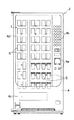
以下、図面を参照しながら、本発明を適用した自動販売機の商品収納装置について説明する。図1〜図3に示すように、この自動販売機2は、缶飲料やパック詰め飲料などの実際の販売商品を外部から視認できるようにした、いわゆるシースルータイプのものである。自動販売機2は、本発明に係る商品収納装置1を収容する販売機本体3と、販売機本体3の前面に取り付けられたメインドア4と、販売機本体3とメインドア4の間に位置する透明断熱扉5とを備えている。
【0023】
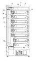
図2および図3に示すように、販売機本体3内には、商品収納装置1の一部を構成する複数の商品ラック10が設けられている。本実施形態では、上下8段で、左右に3列、計24個の商品ラック10が配置されており、各商品ラック10に同一種類の商品Sが収納される。
【0024】
一方、メインドア4の前面には、金銭投入部4a、複数の商品選択ボタン4b、商品取出口4c、および商品ディスプレイを構成する前面窓4dなどが設けられている。商品選択ボタン4bは、商品ラック10と同数および同配置でマトリックス状に配置されている。ユーザーは、商品購入時に、金銭投入部4aに金銭を投入し、購入しようとする商品Sを収納する商品ラック10に対応する商品選択ボタン4bを押すことにより、商品Sを選択する。また、販売機本体3内の商品ラック10の前側の空間には、エレベータ6が設けられており、販売時に商品ラック10から払い出された商品Sは、エレベータ6の載置板6aに載せられた後、底部に設けたシャッタ3a付近まで搬送され、シャッタ3aを介して、商品取出口4cに搬出される。
【0025】
各商品ラック10は、図4および図5などに示すように、ラック本体11と、その前端部に取り付けられた枠体12とを備えている。ラック本体11は、折曲げ加工された鋼板で構成されており、その内部には、中央の仕切壁13で仕切られた左右の商品通路14、14が形成されている。各商品通路14の前端部には、払出口14aが形成されている。
【0026】
一方、枠体12は、合成樹脂(例えばポリプロピレン)の一体成形品で枠状に構成され、ラック本体11の前端部にはめ込まれ、ねじで固定されている。枠体12の前部には、商品通路14の底面に連なる前下がりに傾斜した傾斜ガイド面12bが形成されており、傾斜ガイド面12bには、商品Sの摩擦抵抗を軽減するために、前後方向に延びる複数の長溝12cが形成されている。
【0027】
以上のように構成された商品ラック10は、販売機本体3内に設けた棚(図示せず)に、ローラ16などを介して、前後方向に移動自在に載置されており、商品Sの補充時には、販売機本体3から前方に引き出され、各商品通路14に商品Sが前後方向に並んだ状態で収納されるとともに、補充後、販売機本体3内に押し戻され、格納される(図3参照)。
【0028】
また、図3に示すように、上段の棚から下方に突出するようにして、商品通路14ごとにプッシャ29が設けられている。このプッシャ29は、ばね(図示せず)によって前方に付勢されているとともに、ガイドレール30に沿って前後方向に移動自在に構成されていて、商品Sを常時、前方に押圧している。
【0029】
商品収納装置1はさらに、販売時に商品Sを払い出すための払出機構17を備えている。この払出機構17は、図4および図5に示すように、両商品通路14、14の前端の払出口14a、14aを開閉して、最前位の商品(販売商品)S1を払い出す左右の開閉板18、18(開閉部材)と、これらの開閉板18を付勢するばね(図示せず)と、両開閉板18、18を係止・解放する係止板19と、販売時に前から2番目の商品(次販商品)S2を保持する左右のホルダ20、20と、係止板19およびホルダ20を駆動する駆動機構(図示せず)などで構成されている。
【0030】
開閉板18は、透明な合成樹脂(例えばポリカーボネート)で構成され、その前面には半円弧状の突起23が形成されている。また、各開閉板18は、商品ラック10の中央部に鉛直軸線を中心として回動自在に支持され、商品通路14の払出口14aを閉鎖する閉鎖位置と、開放する開閉位置との間で回動可能である。また、各開閉板18は、上記ばねにより、常時、開放位置側に付勢されている。
【0031】
一方、係止板19は、不透明な合成樹脂(例えばポリアセタール)製の円形板で構成され、その下端部が、駆動機構の駆動軸(図示せず)の先端に固定されている。なお、この駆動軸は、仕切壁13を前後方向に貫通しており、商品Sの販売時に、駆動機構の作動に伴い回転して、係止板19を回動させるようになっている。
【0032】
各ホルダ20は、図5に示すように、折り曲げた板状のものであり、仕切壁13内に立設された支軸(図示せず)に、後端部が回動自在に支持されている。また、両ホルダ20、20は、販売待機時には、商品通路14から退避する退避位置(図5の位置)に位置する一方、販売時には、上記駆動機構の駆動軸の回転に伴って、突出位置(図11の位置)に同時に回動し、両商品通路14、14に突出して、それぞれの次販商品S2を側壁14bとの間に挟持するようになっている。
【0033】
図4および図5などに示すように、商品ラック10にカップ形状の商品S(図8など参照)を収納する場合には、商品ラック10にさらに、アダプタ31およびアダプタ材32が取り付けられる。
【0034】
アダプタ31は、仕切壁13の上面前端部に取り付けられるものであり、図6および図7に示すように、断面コ字形のベース33と、ベース33から立設した支軸34、34に鉛直軸線回りに回動自在にそれぞれ取り付けられた左右のアーム35、35と、ベース33に設けられたプッシュロックボタン36と、を備えている。各アーム35は、支軸34の前側の係止部35aと、後ろ側の送出部35bで構成されている。
【0035】
送出部35b、35bは、内方に屈曲した形状をそれぞれ有するとともに、先端部には、重なり合えるような切欠き35c、35cがそれぞれ形成されている。また、係止部35a、35aは、直線状のものであり、両者間に設けられたコイルばね37によって、内方に常時、付勢されている。プッシュロックボタン36は、例えば弾性を有する樹脂で構成され、ベース33を上下方向に貫通して突出するようにして、設けられている。
【0036】
以上の構成のアダプタ31は、図5〜図7に示すように、そのベース33を仕切壁13の上面にはめ込み、プッシュロックボタン36を仕切壁13の上面に形成した取付孔13aに差し込むことによって、仕切壁13に着脱自在に取り付けられる。また、アダプタ31を取り付ける際には、アーム35、35の係止部35a、35aは、コイルばね37のばね力に抗して押し広げられた状態で、閉鎖位置にある開閉板18、18にそれぞれ係止される。この状態では、アーム35の送出部35bは、図6に2点鎖線で示すように、プッシュロックボタン36の付近で畳まれ、商品通路14から退避した状態になる。
【0037】
アダプタ材32は、折曲げ加工された鋼板で構成され、その係止突起32aを、商品通路14の側壁14bの上面に形成した係止溝14cに係合させることによって、各側壁14bに着脱自在に取り付けられている。アダプタ材32には、傾斜ガイド面32bおよび湾曲ガイド面32cが形成されている。傾斜ガイド面32bは、商品Sを前後方向に案内するためのものであり、図9に示すように、収納するカップ形状商品の側面の傾斜角度に合致する角度で、商品通路14の内方に向かって傾斜している。また、湾曲ガイド面32cは、販売商品Sを案内するものであり、図10に示すように、側壁14bの前端部に位置して、外方に円弧状に延びている。
【0038】
次に、上記構成の商品収納装置1の動作を、特にカップ形状の商品Sを収納した場合について、図8〜図12を参照しながら説明する。図8〜図10に示す販売待機状態では、係止板19は、駆動機構によりホームポジションに保持され、左右の開閉板18、18に前側から当接して、これらを閉鎖位置に係止している。この状態で、多数の商品Sが各商品通路14内に前後方向に並んで収納され、閉鎖位置にある開閉板18とプッシャ29との間に挟持されている。また、ホルダ20は、退避位置に位置し、商品通路14から退避している。さらに、アダプタ31は、そのアーム35、35の係止部35a、35aが、コイルばね37のばね力に抗して押し広げられた状態で、開閉板18、18の背面にそれぞれ係止されていて、送出部35b、35bは、商品通路14から退避した状態になっている。
【0039】
商品の販売時には、駆動機構の駆動軸が回転することにより、図11に示すように、まず、両ホルダ20、20が、突出位置に同時に回動して、それぞれの商品通路14に突出することにより、次販商品S2を、対向する側壁14bとの間に挟持する。駆動軸の回転が進み、係止板19が所定角度まで右側に回動すると、左側の開閉板18から係止板19が外れ、開閉板18が図示しないばねの付勢力で開放位置に回動して、左側の商品通路14の払出口14aを開放する。この開閉板18の開放に伴い、アダプタ31のアーム35の係止部35aが開閉板18から外れ、送出部35bがコイルばね37のばね力で商品通路14に突出し、販売商品S1を勢い良く払出口14a側に送り出すことによって、販売商品S1が商品通路14から払い出される。
【0040】
以上のように、本実施形態の商品収納装置1によれば、開閉板18の開放と連動して、アダプタ31のアーム35の送出部35bが販売商品S1のみを払出口14a側に送り出すので、商品Sがカップ形状商品で、販売商品S1と次販商品S2の間にキャップなどによる引っ掛かりが生じている場合であっても、ホルダ20で保持された次販商品S2から販売商品S1を強制的に引き離すことができ、したがって、販売商品S1を確実に払い出すことができる。また、開閉板18の開放動作を利用してアダプタ31のアーム35を作動させるので、アダプタ31の送出動作を、開閉板18の開放動作に確実に連動させることができるとともに、アダプタ31の駆動力はコイルばね37のばね力だけでよく、比較的単純に構成できる。さらに、アダプタ31で販売商品S1を送り出す際、販売商品S1が、アダプタ材32の外方に湾曲する湾曲ガイド面32cによって、外方に逃げるようにして商品通路14の払出口14a側に導かれるので、販売商品S1を、アダプタ31の送出部35bと商品通路14の側壁14bとの間に挟み込むことなく、円滑に払い出すことができる。
【0041】
また、アーム35の突出回動が終了した時点では、図11および図12に示すように、送出部35bの先端が、ホルダ20にすでに保持されている次販商品S2に前方から当接するようになる。この場合、送出部35bは、図12に示すように、ホルダ20よりも高い位置で次販商品S2に当接する。したがって、次販商品S2がプッシャ29の押圧力で前方に傾いている場合であっても、次販商品S2の上部に送出部35bが前方から当接することによって、次販商品S2を適正な姿勢に整えることができる。
【0042】
その後、駆動機構が再び作動することにより、係止板19がホームポジションまで復帰回動するのに伴い、開閉板18が係止板19に押圧されて閉鎖位置に戻る。これに伴い、アダプタ31の係止部35aが、開閉板18によってコイルばね37のばね力に抗して押し広げられることによって、アーム35が図10に示す位置まで回動し、送出部35bが商品通路14から退避する。また、ホルダ20も、退避位置に回動して、商品通路14から退避する。これに伴い、商品S全体が、プッシャ29の押圧力で開閉板18に当接するまで前方に移動することで、商品収納装置1は、図10に示す販売待機状態に復帰する。この場合、上述したように、それまでの次販商品S2が、アダプタ31の送出部35bによって、適正な姿勢に整えられていること、および、カップ形状の商品Sの側面が、アダプタ材32の傾斜ガイド面32bによって案内されることから、販売待機状態へ移行するための商品Sの移動を円滑に行えるとともに、良好なディスプレイ効果を得ることができる。
【0043】
また、アダプタ31自体が比較的単純で安価に構成できるとともに、プッシュロックボタン36を仕切壁13の取付孔13aに差し込むだけで、アダプタ31を簡単に着脱することができ、したがって、商品通路14を、カップ形状商品の収納用と他形状の商品の収納用とに、簡単に切り替えて使用することができる。
【0044】
なお、本発明は、説明した実施形態に限定されることなく、種々の態様で実施することができる。例えば、販売商品を送出するための送出手段の構成は、実施形態に示したものに限らず、任意である。その他、本発明の趣旨の範囲内で、細部の構成を適宜、変更することが可能である。
【0045】
【発明の効果】
以上のように、本発明の自動販売機の商品収納装置によれば、商品がカップ形状商品の場合でも、商品を確実に1個ずつ払い出すことができ、販売待機状態への移行を円滑に行えるとともに、ディスプレイ効果を向上させることができるなどの効果を有する。
【図面の簡単な説明】
【図1】本発明の実施形態による商品収納装置を搭載した自動販売機の正面図である。
【図2】図1の自動販売機の扉を開いた状態を示す正面図である。
【図3】図1の自動販売機の側断面図である。
【図4】商品収納装置を、アダプタおよびアダプタ材の取付け前の状態で示す斜視図である。
【図5】図4の商品収納装置の前部を、組立後の状態で示す部分斜視図である。
【図6】アダプタの構成および動作を示す平面図である。
【図7】図6のアダプタの正面図である。
【図8】図5の商品収納装置にカップ形状商品を収納した状態を示す斜視図である。
【図9】図8の商品収納装置の正面図である。
【図10】図8の商品収納装置の平面図である。
【図11】商品の販売時における商品収納装置の平面図である。
【図12】商品の販売時における商品収納装置の側面図である。
【図13】 本出願人がすでに提案した商品収納装置の斜視図である。
【符号の説明】
1 商品収納装置
2 自動販売機
10 商品ラック
13 仕切壁
13a 取付孔
14 商品通路
14a 払出口
14b 側壁
18 開閉板
20 ホルダ
29 プッシャ
31 アダプタ
32 アダプタ材
32b 傾斜ガイド面
32c 湾曲ガイド面
33 ベース
34 支軸
35 アーム
35a 係止部
35b 送出部
36 プッシュロックボタン
37 コイルばね
S 商品
S1 販売商品
S2 次販商品[0001]
BACKGROUND OF THE INVENTION
The present invention relates to a product storage device for a vending machine of a type in which a large number of products are stored side by side in a product passage in the product passage and one product is paid out from the front side of the product passage at the time of sale.
[0002]
[Prior art]
A product storage device for this type of vending machine has already been proposed, for example, in Japanese Patent Application No. 8-355374. As shown in FIG. 13, in the
[0003]
The opening /
[0004]
When the product S is sold, the drive mechanism operates and the
[0005]
[Problems to be solved by the invention]
However, the above-described
[0006]
When such a catching phenomenon occurs between the sales product S and the next sales product S, the above-described
[0007]
The present invention has been made to solve such a problem, and even when the product is a cup-shaped product, the products can be paid out one by one without fail, and the transition to the sales standby state can be made smoothly. An object of the present invention is to provide a product storage device for a vending machine that can perform the display effect and improve the display effect.
[0008]
[Means for Solving the Problems]
In order to achieve this object, a product storage device for a vending machine according to the present invention has a product outlet having a discharge outlet at the front end and formed with a product passage for storing a large number of products arranged in the front-rear direction, and a payment for the product passage. An opening / closing member that can be rotated between an open position for opening the outlet and a closed position for closing, and that disposes the sold product from the product passage by turning to the open position at the time of sale, and the product stored in the product passage Can be rotated between a pusher that pushes forward, a protruding position that protrudes into the product path, and a retracted position that retracts from the product path, and holds the next sale product by rotating to the protruding position at the time of sale. It is characterized by comprising a holder and a sending means for sending the sold product by pressing it toward the payout side in conjunction with the rotation of the opening / closing member to the open position.
[0009]
According to the product storage device of this vending machine, in the sales standby state, the opening / closing member is located at the closed position and the outlet of the product passage is closed, and the product is placed between the opening / closing member and the pusher. In a sandwiched state, they are stored side by side in the front-rear direction in the product passage. Further, the holder is located at the retracted position and is retracted from the product passage. When selling a product, the holder first rotates to the protruding position and protrudes into the product passage, thereby holding the next sales product (the second product from the front). Next, the opening / closing member rotates to the open position to open the outlet of the product passage. In conjunction with the opening of the opening / closing member, the delivery means sends out the sale product (the foremost product) by pushing it toward the delivery outlet side, thereby delivering the sale product from the product rack. Thus, in the present invention, in conjunction with the opening of the opening / closing member, the sending means sends out the sold product by pressing only the sold product to the payout side, so the product is a cup-shaped product, and between the sold product and the next sold product. Even if the cap is caught by a cap or the like, the sold product can be forcibly separated from the next sold product held by the holder, and therefore the sold product can be surely paid out.
[0010]
Furthermore, the product storage device of the vending machine according to the present invention is configured such that the product passage is composed of left and right product passages partitioned from each other by a partition wall, and the holder is a left and right holder rotatably attached to the partition wall. The delivery means is composed of an adapter attached to the front end portion of the upper surface of the partition wall. The adapter has a support shaft, and a base attached to the partition wall and a vertical to the support shaft of the base. The left and right arms each having a front-side locking portion and a rear-side feeding portion of the support shaft and the locking portions of the left and right arms are biased toward each other. And the left and right arm locking portions are locked to the opening and closing member in a state of spreading against the spring force of the spring when the opening and closing member is in the closed position. In the state where the locking part spreads, the quotient Retracted from the passage, and is characterized by having a shape as to protrude commodity passage feeding the commodities to discharge opening side when the locking portion is narrowed.
[0011]
In this configuration, the product passage is composed of two rows on the left and right, the holder is also composed of two on the left and right for both product passages, and the delivery means is composed of an adapter attached to the upper surface of the partition wall that partitions the product passage. Yes. In the standby state, the pair of locking portions of the adapter are locked against the opening / closing member in the closed position in a state of spreading against the spring force of the spring. Is evacuated from the merchandise passage. When the product is sold, the locking portion of the adapter is unlocked by turning the opening / closing member to the open position, and the locking portion is narrowed by the spring force of the spring. Thereby, a sending-out part protrudes in a goods passage, and sends out sales goods to the discharge outlet side with the spring force of a spring. Therefore, it is possible to forcibly separate the sales product from the next sales product and pay it out reliably. In addition, since the adapter is operated using the opening operation of the opening and closing member, it is possible to reliably perform the delivery operation of the sale product by the adapter in conjunction with the opening operation of the opening and closing member, and the driving force of the adapter is the spring force. Only a spring force is required, and the structure can be relatively simple.
[0012]
In this case, it is preferable that the sending part of the adapter has a shape that sends out the sold product to the payout side and makes contact with the next sold product from the front.
[0013]
In this configuration, the delivery unit of the adapter not only sends out the sales product to the payout side, but also comes into contact with the next sales product already held by the holder from the front. In this case, since the adapter is provided on the upper surface of the partition wall, the delivery unit comes into contact with the next sale product at a position higher than the holder. Therefore, even if the next-sale product is held in a state where it is tilted forward by the pressing force of the pusher, the next-sale product is made appropriate by contacting the upper part of the next-sale product from the front from the front. Can be adjusted to a proper posture. As a result, it is possible to smoothly move the entire product for shifting to the next sales standby state after the payout operation, and to obtain a good display effect.
[0014]
In these cases, it is preferable that the adapter is detachably attached to the partition wall.
[0015]
In this configuration, since the adapter is detachable, the merchandise passage can be switched between being used for storing cup-shaped products and storing products of other shapes.
[0016]
In this case, the adapter preferably includes a push lock button made of an elastic material provided on the base, and an attachment hole for detachably inserting the push lock button is formed on the upper surface of the partition wall.
[0017]
According to this configuration, the structure for attaching and detaching the adapter is simple, and the adapter can be easily attached and detached simply by inserting the push lock button into the attachment hole.
[0018]
In these cases, the adapter material further includes an adapter material that is detachably attached to the side wall of the product passage facing the partition wall, and the adapter material is curved outward at the front end portion of the side wall to guide the sold product to the payout side. It is preferable to have a curved guide surface.
[0019]
In this configuration, when the sales product is sent out by the adapter, the sales product is guided to the outlet side of the product passage so as to escape outward by the curved guide surface curved outward of the adapter material. It is possible to smoothly dispense from the dispensing outlet without being sandwiched between the delivery portion and the side wall of the product passage.
[0020]
In this case, it is preferable that the adapter material further has an inclined guide surface that extends in the front-rear direction along the side wall and is inclined at a predetermined angle toward the inside of the product passage.
[0021]
In this configuration, when the product is a cup-shaped product, the angle of the inclined guide surface of the adapter material is determined so as to match the inclination angle of the side surface of the cup-shaped product, and the product is put on the side wall to shift to the next sales standby state. The goods can be moved more smoothly.
[0022]
DETAILED DESCRIPTION OF THE INVENTION
Hereinafter, a product storage device of a vending machine to which the present invention is applied will be described with reference to the drawings. As shown in FIGS. 1 to 3, the
[0023]
As shown in FIGS. 2 and 3, a plurality of
[0024]
On the other hand, on the front surface of the
[0025]
Each
[0026]
On the other hand, the
[0027]
The
[0028]
Further, as shown in FIG. 3, a
[0029]
The
[0030]
The opening /
[0031]
On the other hand, the locking
[0032]
As shown in FIG. 5, each
[0033]
As shown in FIGS. 4 and 5, when a cup-shaped product S (see FIG. 8 or the like) is stored in the
[0034]
The
[0035]
The sending
[0036]
As shown in FIGS. 5 to 7, the
[0037]
The
[0038]
Next, the operation of the
[0039]
When the product is sold, when the drive shaft of the drive mechanism rotates, as shown in FIG. 11, first, both
[0040]
As described above, according to the
[0041]
Further, when the projecting and turning of the
[0042]
Thereafter, when the driving mechanism is actuated again, as the locking
[0043]
In addition, the
[0044]
In addition, this invention can be implemented in various aspects, without being limited to the described embodiment. For example, the configuration of the sending means for sending the sales product is not limited to that shown in the embodiment, but is arbitrary. In addition, it is possible to appropriately change the detailed configuration within the scope of the gist of the present invention.
[0045]
【The invention's effect】
As described above, according to the product storage device of the vending machine of the present invention, even when the product is a cup-shaped product, it is possible to reliably pay out the products one by one and smoothly shift to the sales standby state. It can be performed, and the display effect can be improved.
[Brief description of the drawings]
FIG. 1 is a front view of a vending machine equipped with a product storage device according to an embodiment of the present invention.
FIG. 2 is a front view showing a state in which the door of the vending machine of FIG. 1 is opened.
FIG. 3 is a side sectional view of the vending machine shown in FIG. 1;
FIG. 4 is a perspective view showing the product storage device in a state before the adapter and the adapter material are attached.
5 is a partial perspective view showing the front part of the product storage device of FIG. 4 in a state after assembly.
FIG. 6 is a plan view showing the configuration and operation of the adapter.
7 is a front view of the adapter of FIG. 6. FIG.
8 is a perspective view showing a state in which a cup-shaped product is stored in the product storage device of FIG. 5. FIG.
9 is a front view of the product storage device of FIG. 8. FIG.
10 is a plan view of the product storage device of FIG. 8. FIG.
FIG. 11 is a plan view of the product storage device when the product is sold.
FIG. 12 is a side view of the product storage device when the product is sold.
FIG. 13 is a perspective view of a product storage device that the applicant has already proposed.
[Explanation of symbols]
DESCRIPTION OF
Claims (6)
前記商品通路の前記払出口を開放する開放位置と、閉鎖する閉鎖位置との間で回動可能で、販売時に前記開放位置に回動することにより販売商品を前記商品通路から払い出す開閉部材と、
前記商品通路に収納された商品を前方に押圧するプッシャと、
前記商品通路に突出する突出位置と、この商品通路から退避する退避位置との間で回動可能で、販売時に前記突出位置に回動することにより次販商品を保持するホルダと、
前記開閉部材の前記開放位置への回動に連動して、販売商品を前記払出口側へ押圧することにより送り出す送出手段と、
を備えていることを特徴とする自動販売機の商品収納装置であって、
前記商品通路が、仕切壁によって互いに仕切られた左右の商品通路で構成され、前記ホルダが、前記仕切壁に回動自在に取り付けられた左右のホルダで構成されるとともに、
前記送出手段は、前記仕切壁の上面前端部に取り付けられたアダプタで構成され、このアダプタは、
支軸を有し、前記仕切壁に取り付けられたベースと、
このベースの前記支軸に鉛直軸線回りに回動自在にそれぞれ取り付けられ、各々が、前記支軸の前側の係止部と後ろ側の送出部を有する左右のアームと、
これら左右のアームの前記係止部を近づき合う方向に付勢するばねと、を備え、
前記左右のアームの前記係止部は、前記開閉部材が前記閉鎖位置にあるとき、前記ばねのばね力に抗して広がった状態で前記開閉部材に係止されるとともに、前記送出部は、前記係止部が広がった状態では前記商品通路から退避し、かつ前記係止部が狭まったときに前記商品通路に突出して販売商品を前記払出口側へ送り出すような形状を有することを特徴とする、自動販売機の商品収納装置。A merchandise rack having a merchandise passage for storing a large number of merchandise side by side in the front-rear direction and having a dispensing outlet at the front end;
An opening / closing member that is pivotable between an open position that opens the payout opening of the commodity passage and a closed position that closes the commodity passage; ,
A pusher for pushing the product stored in the product passage forward;
A holder that is pivotable between a projecting position projecting into the product path and a retracted position retracting from the product path, and holding a next sale product by pivoting to the projecting position at the time of sale;
In conjunction with the rotation of the opening and closing member to the open position, the sending means for sending out the sold product by pressing it toward the payout side,
A vending machine product storage device characterized by comprising:
The product passage is composed of left and right product passages partitioned from each other by a partition wall, and the holder is composed of left and right holders rotatably attached to the partition wall,
The delivery means is composed of an adapter attached to the upper front end of the partition wall,
A base having a spindle and attached to the partition;
Left and right arms, each of which is attached to the support shaft of the base so as to be rotatable around a vertical axis, each having a front locking portion and a rear delivery portion of the support shaft,
A spring that urges the locking portions of the left and right arms in a direction approaching,
The locking portions of the left and right arms are locked to the opening / closing member in a state of spreading against the spring force of the spring when the opening / closing member is in the closed position, and the sending portion is It has a shape that retracts from the commodity passage in a state where the locking portion is widened, and protrudes into the commodity passage when the locking portion is narrowed so as to send the sold product to the payout side. Vending machine product storage device .
Priority Applications (1)
| Application Number | Priority Date | Filing Date | Title |
|---|---|---|---|
| JP16531197A JP3800733B2 (en) | 1997-06-06 | 1997-06-06 | Vending machine product storage device |
Applications Claiming Priority (1)
| Application Number | Priority Date | Filing Date | Title |
|---|---|---|---|
| JP16531197A JP3800733B2 (en) | 1997-06-06 | 1997-06-06 | Vending machine product storage device |
Publications (2)
| Publication Number | Publication Date |
|---|---|
| JPH10340383A JPH10340383A (en) | 1998-12-22 |
| JP3800733B2 true JP3800733B2 (en) | 2006-07-26 |
Family
ID=15809927
Family Applications (1)
| Application Number | Title | Priority Date | Filing Date |
|---|---|---|---|
| JP16531197A Expired - Fee Related JP3800733B2 (en) | 1997-06-06 | 1997-06-06 | Vending machine product storage device |
Country Status (1)
| Country | Link |
|---|---|
| JP (1) | JP3800733B2 (en) |
Families Citing this family (4)
| Publication number | Priority date | Publication date | Assignee | Title |
|---|---|---|---|---|
| JP4888168B2 (en) * | 2007-03-13 | 2012-02-29 | 富士電機リテイルシステムズ株式会社 | Vending machine product storage device |
| CN106875565A (en) * | 2017-01-04 | 2017-06-20 | 广州品帝智能科技有限公司 | A kind of beverage vending machine carrying device |
| KR102058416B1 (en) * | 2019-09-19 | 2019-12-24 | 이상현 | EM microbial auto feeder |
| CN111887679B (en) * | 2020-08-07 | 2021-08-27 | 陈竹 | Special display cabinet convenient to take according to packets for tobacco retail |
-
1997
- 1997-06-06 JP JP16531197A patent/JP3800733B2/en not_active Expired - Fee Related
Also Published As
| Publication number | Publication date |
|---|---|
| JPH10340383A (en) | 1998-12-22 |
Similar Documents
| Publication | Publication Date | Title |
|---|---|---|
| US8002144B2 (en) | Drive system for a vending machine dispensing assembly | |
| US5392953A (en) | Cold drink vending machine with window front panel | |
| US4087020A (en) | Article vending machine having rotary storage compartments | |
| JP2001014543A (en) | Device and method for housing merchandise for automatic vending machine | |
| JP3800733B2 (en) | Vending machine product storage device | |
| US2847146A (en) | Vending machines for packaged merchandise or the like | |
| US2952384A (en) | Vending machine | |
| JP3511194B2 (en) | Vending machine product unloading device | |
| US2888168A (en) | Aperture delivery cigarette merchandising machine | |
| JP3478065B2 (en) | Vending machine product storage device | |
| JP4289780B2 (en) | Merchandise storage and dispensing device for vending machines | |
| EP1006495B1 (en) | Article storage device for vending machine | |
| JP5458866B2 (en) | vending machine | |
| JP4888054B2 (en) | Product storage device | |
| EP1006496A1 (en) | Article container for automatic vending machine | |
| KR100231771B1 (en) | Commodity ejecting device and method in the spiral type vending machine | |
| JP3478066B2 (en) | Vending machine product storage device | |
| JP2685231B2 (en) | Vending machine product unloading device | |
| JP2541013Y2 (en) | Vending machine product unloading device | |
| JP2000149129A (en) | Article storage and discharge device for automatic vending machine | |
| JPH10255140A (en) | Commodity storage device for automatic vending machine | |
| JP3826514B2 (en) | Merchandise storage and dispensing device for vending machines | |
| JP2533669Y2 (en) | Vending machine product storage device | |
| JP2002150414A (en) | Device for storing and delivering article for vending machine | |
| JP2000090344A (en) | Merchandise pay-out device for automatic vending machine |
Legal Events
| Date | Code | Title | Description |
|---|---|---|---|
| A977 | Report on retrieval |
Free format text: JAPANESE INTERMEDIATE CODE: A971007 Effective date: 20041216 |
|
| A131 | Notification of reasons for refusal |
Free format text: JAPANESE INTERMEDIATE CODE: A131 Effective date: 20041228 |
|
| A521 | Written amendment |
Free format text: JAPANESE INTERMEDIATE CODE: A523 Effective date: 20050221 |
|
| A02 | Decision of refusal |
Free format text: JAPANESE INTERMEDIATE CODE: A02 Effective date: 20050809 |
|
| A521 | Written amendment |
Free format text: JAPANESE INTERMEDIATE CODE: A523 Effective date: 20050908 |
|
| A911 | Transfer of reconsideration by examiner before appeal (zenchi) |
Free format text: JAPANESE INTERMEDIATE CODE: A911 Effective date: 20051012 |
|
| TRDD | Decision of grant or rejection written | ||
| A01 | Written decision to grant a patent or to grant a registration (utility model) |
Free format text: JAPANESE INTERMEDIATE CODE: A01 Effective date: 20060411 |
|
| A61 | First payment of annual fees (during grant procedure) |
Free format text: JAPANESE INTERMEDIATE CODE: A61 Effective date: 20060424 |
|
| R150 | Certificate of patent or registration of utility model |
Free format text: JAPANESE INTERMEDIATE CODE: R150 |
|
| FPAY | Renewal fee payment (event date is renewal date of database) |
Free format text: PAYMENT UNTIL: 20090512 Year of fee payment: 3 |
|
| FPAY | Renewal fee payment (event date is renewal date of database) |
Free format text: PAYMENT UNTIL: 20100512 Year of fee payment: 4 |
|
| FPAY | Renewal fee payment (event date is renewal date of database) |
Free format text: PAYMENT UNTIL: 20110512 Year of fee payment: 5 |
|
| FPAY | Renewal fee payment (event date is renewal date of database) |
Free format text: PAYMENT UNTIL: 20110512 Year of fee payment: 5 |
|
| FPAY | Renewal fee payment (event date is renewal date of database) |
Free format text: PAYMENT UNTIL: 20120512 Year of fee payment: 6 |
|
| S531 | Written request for registration of change of domicile |
Free format text: JAPANESE INTERMEDIATE CODE: R313531 |
|
| FPAY | Renewal fee payment (event date is renewal date of database) |
Free format text: PAYMENT UNTIL: 20120512 Year of fee payment: 6 |
|
| R350 | Written notification of registration of transfer |
Free format text: JAPANESE INTERMEDIATE CODE: R350 |
|
| FPAY | Renewal fee payment (event date is renewal date of database) |
Free format text: PAYMENT UNTIL: 20120512 Year of fee payment: 6 |
|
| FPAY | Renewal fee payment (event date is renewal date of database) |
Free format text: PAYMENT UNTIL: 20130512 Year of fee payment: 7 |
|
| FPAY | Renewal fee payment (event date is renewal date of database) |
Free format text: PAYMENT UNTIL: 20130512 Year of fee payment: 7 |
|
| S111 | Request for change of ownership or part of ownership |
Free format text: JAPANESE INTERMEDIATE CODE: R313111 |
|
| FPAY | Renewal fee payment (event date is renewal date of database) |
Free format text: PAYMENT UNTIL: 20130512 Year of fee payment: 7 |
|
| R350 | Written notification of registration of transfer |
Free format text: JAPANESE INTERMEDIATE CODE: R350 |
|
| FPAY | Renewal fee payment (event date is renewal date of database) |
Free format text: PAYMENT UNTIL: 20130512 Year of fee payment: 7 |
|
| FPAY | Renewal fee payment (event date is renewal date of database) |
Free format text: PAYMENT UNTIL: 20140512 Year of fee payment: 8 |
|
| LAPS | Cancellation because of no payment of annual fees |