JP3800341B2 - Louver glass - Google Patents
Louver glass Download PDFInfo
- Publication number
- JP3800341B2 JP3800341B2 JP2004051229A JP2004051229A JP3800341B2 JP 3800341 B2 JP3800341 B2 JP 3800341B2 JP 2004051229 A JP2004051229 A JP 2004051229A JP 2004051229 A JP2004051229 A JP 2004051229A JP 3800341 B2 JP3800341 B2 JP 3800341B2
- Authority
- JP
- Japan
- Prior art keywords
- glass
- louver
- layer
- laminated glass
- laminated
- Prior art date
- Legal status (The legal status is an assumption and is not a legal conclusion. Google has not performed a legal analysis and makes no representation as to the accuracy of the status listed.)
- Expired - Fee Related
Links
Images


Description
本発明は住宅等建造物の開口部等に設置のルーバー窓に用いられるルーバーガラス(羽根ガラス、ジャロジーガラスとも言う)に関するものであって、その防犯対策に係り、ルーバーガラスがガラス切やニッパーの類によって刻まれた傷を起点に割られたり、その他強引に割り破られたりする被害や、ルーバーガラスが支持金具から抜き外されたりする被害の防止に効果を有する。 The present invention relates to a louver glass (also referred to as a blade glass or jalousie glass) used for a louver window installed in an opening or the like of a building such as a house, and relates to a crime prevention measure. It is effective in preventing damages such as cracks carved by a kind from the starting point, and other breaching damages, and damage to the louver glass being removed from the support bracket.
従来、ルーバー窓の種類には、ルーバーガラスの両端にエンドキャップを被せて支持金具に挿入すればワンタッチ操作的に装着とロックとが同時に行えるエンドキャップ装着のルーバー窓と、装着機能のみでロック機能のないクリップ式支持金具を備えるクリップ装着のルーバー窓とがある。 Conventional types of louver windows include louver windows with end caps that can be mounted and locked at the same time by one-touch operation by placing end caps on both ends of the louver glass and inserting them into the support bracket. There is a clip-mounted louver window equipped with a clip-type support bracket without a gap.
図8はルーバー窓の一般的な構成を概略的に示す断面図であり、ルーバーガラスGは従来一般に厚み6.0〜6.8mmの板ガラスが用いられており、エンドキャップ式やクリップ式等の支持金具Kに装着されていて、支持金具Kはルーバー窓の本体部Hに回動自在に取付けられており、連動フレームFを介してオペレータPに連結している。ルーバーガラスGは回動することにより長辺周辺部が鎧状に接触して開閉する構成になっている。 FIG. 8 is a cross-sectional view schematically showing a general configuration of a louver window, and a louver glass G is generally made of a plate glass having a thickness of 6.0 to 6.8 mm, and is generally of an end cap type or a clip type. The support fitting K is attached to the main body H of the louver window, and is connected to the operator P via the interlocking frame F. The louver glass G is configured to open and close by rotating around the long side of the louver glass G in an armor shape.
ルーバー窓における防犯上の問題としては、エンドキャップ装着のルーバー窓やクリップ装着のルーバー窓において裸のルーバーガラス(板ガラスが所定寸法に切断されて面取りされた状態のもの)を用いる場合に、該ルーバーガラスがガラス切ないしはニッパーの類によって刻まれた傷を起点にして割られて抜き取られたり、希にはバール等によって強引に割られたりするという問題があった。以下、この問題は「割り抜き」被害と言うものとする。もう1つの問題としては、ルーバーガラスをロックする機能が備わっていないクリップ装着のルーバー窓においては、支持金具からルーバーガラスが抜き外されるという問題があった。以下、この問題は「抜き外し」被害と言うものとする。 As a security problem in the louver window, when using a louver glass with a cap attached to an end cap or a louver window with a clip attached, bare louver glass (with a glass plate cut into a predetermined size and chamfered) is used. There has been a problem that glass is cracked and pulled out starting from scratches carved by glass cutting or nippers, or rarely forcibly cracked by bar or the like. In the following, this problem is referred to as “discount” damage. Another problem is that the louver glass is removed from the support fitting in a clip-mounted louver window that does not have a function of locking the louver glass. Hereinafter, this problem will be referred to as “unplugging” damage.
近年では、エンドキャップ装着のルーバー窓が大半を占めるに至り、ロック機構のないクリップ装着のルーバー窓は設置が少なくなってきていて、クリップ装着のルーバー窓において発生していた抜き外し被害の問題は終息の方向にある。しかし、割り抜き被害は裸のルーバーガラスを用いる場合に発生する被害であってクリップ装着のルーバー窓においても発生するのであって、防犯上の課題は割り抜き被害の防止に絞られてきている。 In recent years, louver windows with end caps occupy the majority, and louver windows with clip mechanisms without a locking mechanism have been installed less frequently. In the direction of termination. However, the breakage damage is a damage that occurs when a bare louver glass is used, and also occurs in a louver window fitted with a clip, and the problem of crime prevention has been focused on preventing the breakage damage.
中間膜を用いた公知の合せガラスは、ガラス層が割られると容易に撓んで変形し、支持金具から抜き取ることが可能なので、何れのルーバー窓においても厚み6.0〜6.8mmの裸のルーバーガラスが専ら用いられている。ガラス切等で刻まれた傷を起点にしてルーバーガラスが割られて抜き取られる割り抜き被害は、型板ガラスや網入りガラスを裸の状態で用いる場合に発生する被害であって、裸のルーバーガラスが専ら用いられている現状においては全てのルーバー窓において被害の発生する惧れがある。装着とロックとがワンタッチ操作で行えるという優れた機能を有するエンドキャップ装着のルーバー窓と言えども、裸のルーバーガラスを用いる限りにおいては、ガラス切等を用いて分断したり、撓ませたりして抜き取るという割り抜き被害に対しては全くの無防備であって対策を必要としていた。また、裸のルーバーガラスは意匠性に劣るという問題も併せ持っていた。 The known laminated glass using the interlayer film is easily bent and deformed when the glass layer is cracked, and can be removed from the support fitting. Therefore, any louver window has a bare thickness of 6.0 to 6.8 mm. Louver glass is exclusively used. The cut damage caused by louver glass being cracked and extracted from scratches carved by glass cutting, etc., is damage that occurs when template glass or netted glass is used in a bare state. Bare louver glass Currently, there is a risk that damage will occur in all louver windows. Even if it is a louver window with an end cap that has an excellent function that can be attached and locked with one touch operation, as long as bare louver glass is used, it can be broken or bent using glass cutting etc. It was completely defenseless against the unforeseen damage caused by sampling, and needed countermeasures. In addition, the naked louver glass has a problem that it is inferior in design.
割り抜き被害の一例としては、ガラス切による場合は短辺方向に線状傷が入れられ、ニッパー等による場合は側部に噛り傷が入れられ、必要に応じて消音のための粘着テープが貼られ、ルーバーガラスが閉状態の際には鑿やバールや釘抜きの類の先端部を鎧状に重なるルーバーガラスの間隙に差込んで梃子の原理により、開状態の際や2枚目以降の場合にはペンチやヤットコの類で挟んで該傷の箇所に折り曲げ方向の力を加えるようにすればルーバーガラスは該傷を起点に割られて容易に分断されるし、網入りガラスでは折り曲げられる。ルーバーガラスは支持金具に嵌まっているにすぎないので、分断されたり折り曲げられた状態のルーバーガラスは切り口の方向に引っ張れば簡単に抜き取れる。これらに要する時間はルーバーガラス1個当り数秒とは掛からない。 As an example of cutout damage, a linear flaw is made in the short side direction when glass is cut, a bite is put on the side when nippers are used, and an adhesive tape for silencing is used if necessary. When the louvered glass is closed, the tip of the bag, bar, or nail clipper is inserted into the gap between the louvered glass that overlaps the armor. In some cases, the louver glass can be easily divided by being cracked from the scratch if it is sandwiched with pliers or a yatco to apply a force in the direction of bending to the point of the scratch. . Since the louver glass is only fitted to the support fitting, the louver glass in a state of being divided or bent can be easily pulled out by pulling in the direction of the cut end. The time required for these does not take several seconds per louver glass.
なお、因みに述べれば、断面溝形のサッシにグレチャンを介して板ガラスを嵌めたルーバーガラスは、従来一般のガラス窓と同様であってグレチャンには接着力がないため、ガラスが割られれば割られたガラス片はサッシに接着されているのではなくて嵌まっているにすぎないので簡単に外され、ガラス片の外れた開口部から手が入れられてロックが解除されるものであり、割り抜き被害の防止にはなり得ないという問題があった。
また、ルーバー窓の気密性を向上させるため、弾性材から成る気密材をルーバーガラスの長辺近傍に貼着したルーバーガラスが、例えば特開平11−62420号、特開平10−122210号、特開平9−133384号等において提案されているが、弾性材から成る気密材はルーバーガラスが割られる際に一緒に折れ曲がるので、割り抜き被害の防止にはなり得ないという問題があった。
Incidentally, the louver glass in which a plate glass is fitted to a sash having a groove shape in cross section via a grechan is the same as a conventional glass window and has no adhesive force, so if the glass is cracked, it is broken. The glass piece is not glued to the sash, it just fits in, so it is easily removed and the hand is inserted through the opening where the glass piece is removed, and the lock is released. There was a problem that it could not prevent the damage.
Further, in order to improve the airtightness of the louver window, a louver glass in which an airtight material made of an elastic material is attached in the vicinity of the long side of the louver glass is disclosed in, for example, JP-A-11-62420, JP-A-10-122210, Although proposed in No. 9-133384 and the like, the hermetic material made of an elastic material is bent together when the louver glass is cracked, and therefore, there is a problem that it cannot prevent the breakage damage.
割り抜き被害の手口は、ガラス切等を道具として用いることにより素人にも音も出さず失敗なく素早く行える業であって、その手口が泥棒仲間に知れ渡れば従来の抜き外し被害の比ではなく極めて大きな被害に広まる惧れがあり、ルーバー窓の存続にも関わるものと危惧される。本発明は上記危惧に鑑みて為されたものであり、本発明の第1の課題は、上記の割り抜き被害が簡単に防止できる新たな構成のルーバーガラスを提供することにある。更には、その新たな構成のルーバーガラスが世間に受け入れられるためには窓としての美観が必要であって、意匠性に優れた魅力のある構成のルーバーガラスであることが必須であることに鑑み、意匠性の向上も併せて課題としている。 The technique of cutout damage is a work that can be done quickly without failure by using glass cutting etc. as a tool without making any noise, and if the technique is known to thief friends, it is not the ratio of conventional removal damage There is a possibility that it will spread to extremely large damage, and it is feared that it will be related to the survival of the louver window. The present invention has been made in view of the above-mentioned concerns, and a first object of the present invention is to provide a louver glass having a new configuration that can easily prevent the above-mentioned damage caused by cutting. Furthermore, in view of the fact that the louver glass with the new configuration requires acceptance of the aesthetics as a window in order to be accepted by the world, it is essential that the louver glass has an attractive configuration with excellent design. The improvement of the design is also an issue.
本発明の第2の課題は、クリップ装着のルーバー窓を対象としており、ロック機構を備えていないために発生する抜き外し被害を、上記の割り抜き被害を防止する際に同時に防止することにある。抜き外し被害の問題は上記のように終息の方向にはあるが、既設のルーバー窓にはクリップ装着のルーバー窓も多く存在していることに鑑みて為されたものであり、ルーバー窓の本体部は改造することなく、裸のルーバーガラスを本発明のルーバーガラスに取り替えるのみによって抜き外し被害と割り抜き被害とが同時に防止できるようにすることにある。 The second problem of the present invention is directed to a clip-mounted louver window and is intended to prevent unplugging damage that occurs because the lock mechanism is not provided at the same time as preventing the above-mentioned cutting damage. . Although the problem of unplugging damage is in the direction of termination as described above, it was made in view of the fact that there are many clip-attached louver windows in the existing louver windows. The present invention has an object to prevent damage from being removed and cut off at the same time by replacing bare louver glass with the louver glass of the present invention without modification.
上記第1の課題を解決する請求項1記載の発明では、回動することによって開閉する構成のルーバー窓に用いられるルーバーガラスであって該ルーバーガラスの一部の箇所がガラス層と接着材層と耐衝撃材層とから成る合せガラスの構成になっているルーバーガラスにおいて、上記合せガラスの構成になっている合せガラス部は、形成されている箇所がルーバーガラスの周辺部であって、該ルーバーガラスが鎧状に接触する際の接触側がガラス層から成り、反接触側が耐衝撃材層から成るものであることを特徴とするルーバーガラスを提供している。
The invention according to
本発明において合せガラスとは、一方の側が板ガラスから成るものは相手側の材質に関係なく合せガラスの範疇であるとし、全域ではなく一部分のみが合せガラスの構成になっているものも全てが合せガラスの範囲に含まれるものとし、相手側の材質や占める面積には拘らないものとする。耐衝撃材とは、ガラスのように衝撃によって破損する材質のものではなくて、例えば金属や或る種の合成樹脂等のように剛性と粘性を兼ね備えていて衝撃にも耐える高強度の材質のものを言う。公知の合せガラスから成るルーバーガラスは、ガラス層が割られれば容易に撓んで(折れ曲がって)支持金具から簡単に抜き取られるのに対し、請求項1記載のルーバーガラスは周辺部をガラス層と接着材層と耐衝撃材層とから成る合せガラスの構成としており、剛性と粘性を兼ねる高強度な耐衝撃材を相手側に用いることによって、ガラス層が割られた場合にも支持金具から抜き取ることができないようにして割り抜き被害を防止し、且つ、該合せガラス部は周辺部に形成するようにしており相手側が不透明な材質であっても窓に必要な採光を得る構成であって、延いては合せガラス部の描く模様によって意匠性を向上させる構成とした点に特徴を有する。
In the present invention, a laminated glass means that a glass sheet on one side is in the category of laminated glass regardless of the material of the other side, and a laminated glass is composed of only a part of the laminated glass, not the entire area. It shall be included in the glass range, regardless of the material and area occupied by the other party. The impact-resistant material is not made of a material that is damaged by impact like glass, but is made of a high-strength material that has both rigidity and viscosity and can withstand impact, such as metal and some synthetic resins. Say things. The louver glass made of a known laminated glass is easily bent (bent) when the glass layer is broken, and is easily extracted from the support metal, whereas the louver glass according to
請求項1記載のルーバーガラスでは、合せガラス部は、接触側のガラス層と反接触側の耐衝撃材層とが接着剤層を介して向き合う構成とし、1つのガラス層に対して1つの耐衝撃材層を組み合わせた所謂シングル構造の合せガラスとして形成している点に特徴を有する。即ち、製作が容易なシングル構造とすることによってコスト低廉に割り抜き被害を防止し、且つ、厚み3〜5mmの薄い板ガラスを用いた場合にも合せガラスに形成することによって周辺部の厚みを増加させて6mm用支持金具に適合する形状の得られる構成とした点に特徴を有する。
In the louver glass according to
上記第1の課題を解決する請求項2記載の発明では、回動することによって開閉する構成のルーバー窓に用いられるルーバーガラスであって該ルーバーガラスの一部の箇所がガラス層と接着材層と耐衝撃材層とから成る合せガラスの構成になっているルーバーガラスにおいて、上記合せガラスの構成になっている合せガラス部は、形成されている箇所がルーバーガラスの周辺部であって、該ルーバーガラスが鎧状に接触する際の接触側がガラス層から成り、反接触側と側面とが耐衝撃材層から成るものであることを特徴とするルーバーガラスを提供している。 In the invention according to claim 2, which solves the first problem, the louver glass is used in a louver window configured to be opened and closed by rotating, and a part of the louver glass includes a glass layer and an adhesive layer. In the louver glass comprising a laminated glass composed of an impact-resistant material layer, the laminated glass part comprising the laminated glass is formed at a peripheral portion of the louver glass, There is provided a louver glass characterized in that the contact side when the louver glass contacts the armor is made of a glass layer, and the anti-contact side and the side surface are made of an impact-resistant material layer.
請求項2に記載のルーバーガラスにおいては、合せガラス部は、接触側のガラス層を、反接触側の耐衝撃材層と側面の耐衝撃材層とによって異なる2つの方向から覆う構成とし、1つのガラス層に対して2つの耐衝撃材層を組み合わせた所謂ダブル構造の合せガラスとして形成している点に特徴を有する。即ち、反接触側の耐衝撃材層と側面の耐衝撃材層とによる2次元の壁面によってガラス層を保護する構成とすることによって割り抜き被害を強力に防止し、且つ、厚み3〜5mmの薄い板ガラスを用いた場合にも合せガラスに形成することによって周辺部の厚みを増加させて6mm用支持金具に適合する形状の得られる構成とした点に特徴を有する。なお、側面の耐衝撃材層とガラス層との間に介在させる接着材層は省略しても防犯力に支障はないが、省略した場合は、見かけはダブル構造であっても機能としてはシングル構造の範疇となる。 In the louver glass according to claim 2, the laminated glass portion is configured to cover the contact-side glass layer from two different directions depending on the anti-contact side impact-resistant material layer and the side impact-resistant material layer. It is characterized in that it is formed as a so-called double-structured laminated glass in which two impact-resistant material layers are combined with one glass layer. That is, it is possible to strongly prevent the breakage damage by protecting the glass layer with a two-dimensional wall surface by the impact-resistant material layer on the anti-contact side and the impact-resistant material layer on the side surface, and having a thickness of 3 to 5 mm. Even when a thin plate glass is used, it is characterized in that the thickness of the peripheral portion is increased by forming it on a laminated glass so that a shape suitable for a support bracket for 6 mm can be obtained. Note that even if the adhesive layer interposed between the impact-resistant material layer and the glass layer on the side surface is omitted, there is no problem in the crime prevention power. However, if omitted, even if the appearance is a double structure, the function is single. It becomes a category of structure.
上記第1の課題を解決する請求項3記載の発明では、請求項1または請求項2に記載のルーバーガラスにおいて、上記合せガラスの構成になっている合せガラス部は、該ルーバーガラスが支持金具に装着された際に支持金具によって覆い隠される支持金具装着部を除く部分であって、該支持金具の間に露出している露出部に形成されて成るものであることを特徴とするルーバーガラスを提供している。 According to a third aspect of the present invention for solving the first problem, in the louver glass according to the first or second aspect, the laminated glass portion constituting the laminated glass is formed of the louver glass as a support fitting. A louver glass that is formed on an exposed portion that is exposed between the support brackets, except for a support bracket mounting portion that is covered with the support bracket when mounted on the support bracket. Is provided.
請求項3に記載のルーバーガラスにおいては、合せガラス部は露出部に限定して形成するようにして支持金具装着部は裸ガラスの状態のまま残す構成としたことによって、厚みの増加する箇所と増加しない箇所とを目的に応じて機能させる構成としている点に特徴を有する。即ち、第三者からの攻撃の対象となる露出部は厚みが増加する箇所として合せガラス部を設けることによって割り抜き被害を強力に防止し、且つ、支持金具に嵌める支持金具装着部は強度十分な厚み6.0〜6.8mmの板ガラスを用いた場合にも厚みが増加しない箇所として残すようにして6mm用支持金具に適合する形状の得られる構成とした点に特徴を有する。また、請求項3に記載のルーバーガラスでは、優先権主張に係る先の出願の請求項3および段落番号0016に記載しているように、合せガラスの構成になっている合せガラス部は少なくとも何れか一方の長辺の近傍に形成されていれば防犯上は十分である。 In the louver glass according to claim 3, the laminated glass portion is limited to the exposed portion and the support fitting mounting portion is left in a bare glass state, thereby increasing the thickness. It is characterized in that it is configured such that a portion that does not increase functions according to the purpose. In other words, the exposed part that is subject to attack from a third party is strongly prevented from being damaged by providing a laminated glass part as a place where the thickness increases, and the support fitting mounting part fitted to the support fitting is sufficiently strong Even when a plate glass having a thickness of 6.0 to 6.8 mm is used, it is characterized in that it has a configuration in which a shape suitable for the 6 mm support metal fitting is obtained by leaving it as a portion where the thickness does not increase. Further, in the louver glass according to claim 3, as described in claim 3 and paragraph number 0016 of the prior application relating to the claim of priority, at least any of the laminated glass portions constituting the laminated glass If it is formed near one of the long sides, it is sufficient for crime prevention.
上記第2の課題を解決する請求項4記載の発明では、回動することによって開閉する構成のルーバー窓に用いられるルーバーガラスであって該ルーバーガラスの一部の箇所がガラス層と接着材層と耐衝撃材層とから成る合せガラスの構成になっているルーバーガラスにおいて、上記合せガラスの構成になっている合せガラス部は、形成されている箇所がルーバーガラスの周辺部であって、上記合せガラス部を構成する耐衝撃材層が金属層から成り、該金属層には支持金具のクリップ部が開閉する際の軌道上に出現して該クリップ部の動きを封ずる舌片が出退自在に設けられて成るものであることを特徴とするルーバーガラスを提供している。 In the invention according to claim 4, which solves the second problem, the louver glass is used in a louver window configured to open and close by rotating, and a part of the louver glass includes a glass layer and an adhesive layer. In the louver glass having a laminated glass structure composed of a shock-resistant material layer, the laminated glass part having the laminated glass structure is a peripheral part of the louver glass, and The impact-resistant material layer that constitutes the laminated glass part is composed of a metal layer, and a tongue piece that appears on the track when the clip part of the support bracket opens and closes and seals the movement of the clip part comes and goes. Provided is a louver glass characterized by being freely provided.
請求項4記載のルーバーガラスは、ロック機構を有しないクリップ装着のルーバー窓を対象としており、ルーバー窓本体部の改造は全く必要とせず、従来のルーバーガラスを本発明のルーバーガラスに取り替えるのみの手段でもって、取り外し被害と割り抜き被害とを同時に防止するようにした点に特徴を有する。 The louver glass according to claim 4 is intended for a clip-mounted louver window that does not have a lock mechanism, and does not require any modification of the louver window body, and only replaces the conventional louver glass with the louver glass of the present invention. It is characterized in that the removal damage and the breakage damage are prevented at the same time by the means.
請求項1記載のルーバーガラスは、周辺部の接触側がガラス層から成り反接触側が耐衝撃材層から成る合せガラスの構成になっているため、ガラス層が割り抜き被害の攻撃を受けて割られたとしても、相手方の耐衝撃材層は強度が大きくて破断することはないし、接着しているガラス層は耐衝撃材層から剥離されることがなく、原形を維持していて撓む(折れ曲がる)こともない。即ち、本発明のルーバーガラスは、中間膜を用いた従来の合せガラスのように撓むことはなく、支持金具から抜き取られることはないのであって、割り抜き被害は防止される。耐衝撃材層とガラス層は接着されていることによって飛躍的に強化されるものであり、両者の関係はビル建築の鉄骨コンクリートにおける鉄骨とコンクリートとの関係に似ており、鉄骨に該当する耐衝撃材層とコンクリートの骨材に該当するガラス層とがセメントに該当する接着材層によって一体化されて強固な構造を生み出している。このように強固な構造のルーバーガラスは、全域が合せガラスの構成になっている必要はないのであって、周辺部に形成されているのみでも十分な防犯機能を有する。また、周辺部のみが合せガラスの構成になっている構成では、耐衝撃層が不透明な材質のものである場合にも、面積の大半を占める非合せガラス(単板ガラス)の領域から窓に必要な採光は十分に得られる。また、合せガラスの箇所はルーバー窓に固有の横縞模様の意匠を更に強調する存在であり、美観が向上する。
The louver glass according to
請求項1記載のルーバーガラスでは、合せガラス部は、接触側がガラス層から成り反接触側が耐衝撃材層から成る、所謂シングル構造の合せガラスから成るものであり、構造が簡単であって、コストが低廉なわりには機能性に優れている。即ち、割り抜き被害の攻撃を受けた場合には、耐衝撃材層が該ルーバーガラスを周辺部から保護して面格子としての機能を果たし、先ずは第1段目の防衛を果たす。この第1段目の防衛に敗れてガラス層が割られたとしても、割られたガラス片は耐衝撃材層に接着していて撓む(折れ曲がる)ことがなく支持金具から抜き取られることはないのであり、割り抜き被害は耐衝撃材層が果たす面格子機能と、合せガラスが果たすそれ本来の機能との2段構えの機能によって強力に防止される。また、厚さ3〜5mmの薄い板ガラスを用いた場合にも、周辺部は合せガラスの構成にすることによって従来のルーバーガラス並みの6.0〜6.8mmにまで厚みを増加させることができて、6mm用支持金具に適合する厚みが得られ、従来のルーバー窓において互換性100%に用いることができる。また、面積の大半を占める非合せガラスの部分(単板ガラスの部分)は厚さ3〜5mmの薄い板ガラスであって、従来に比べ軽量化が図れる。
In the louver glass according to
請求項2に記載のルーバーガラスでは、合せガラス部は接触側がガラス層から成り、反接触側と側面とが共に耐衝撃材層から成る、所謂ダブル構造の合せガラスから成るものであり、機能は請求項1や2に記載のシングル構造のものに比べれば単純計算で略2倍に強化されている。即ち、ガラス層は反接触側の耐衝撃材層と側面の耐衝撃材層とによる2次元の壁面によって保護されており、一部材としての耐衝撃材層が果たす面格子としての機能と、本体部としての合せガラス部が果たす合せガラス本来の機能は共に請求項1のシングル構造の場合よりも強化されていて、撓みに対する抵抗力が大きくて支持金具から抜き取られることはなく、割り抜き被害は強力に防止される。また、厚さ3〜5mmの薄い板ガラスを用いた場合にも、周辺部は合せガラスの構成にすることによって従来のルーバーガラス並みの6.0〜6.8mmにまで厚みを増加させることができて、6mm用支持金具に適合する厚みが得られ、従来のルーバー窓において互換性100%に用いることができる。また、面積の大半を占める非合せガラスの部分(単板ガラスの部分)は厚さ3〜5mmの薄い板ガラスであって、従来に比べ軽量化が図れる。
In the louver glass according to claim 2, the laminated glass portion is made of a so-called double-structured laminated glass in which the contact side is made of a glass layer, and the anti-contact side and the side face are both made of an impact-resistant material layer, and the function is Compared to the single structure according to
請求項3に記載のルーバーガラスでは、合せガラス部は、支持金具装着部を除く部分であって露出部に限定して形成されているため、厚さ6.0〜6.8mmの板ガラスの周辺部に合せガラス部を形成した場合でも、支持金具装着部分の厚みは増すことがないのであって、6mm用支持金具に適合する形状のままであり、従来のルーバー窓において互換性100%に用いることができる。即ち、本発明のルーバーガラスでは、更に厚みが増加しても装着に影響のない露出部に合せガラス部を形成するようにし、6mm用支持金具に適合するルーバーガラスとしては限度最高の厚みである6.0〜6.8mmの板ガラスを用いて限度最高のガラス強度を得ると同時に、更に厚みが増加すると装着に支障を来たす支持金具装着部には合せガラス部を設けないようにして従来品との互換性を得るようにしている。即ち、泥棒など第三者からの攻撃を直接に受ける露出部分を合せガラスの構成にすることによって得られる面格子機能と合せガラス機能とによって割り抜き被害を防止するものである。要するに、本発明によれば6.0〜6.8mmの板ガラスに合せガラス部を設けた防犯効果十分なルーバーガラスを6mm用支持金具に適合するルーバーガラスとして提供することができる。 In the louver glass according to claim 3, the laminated glass portion is a portion excluding the support fitting mounting portion and is limited to the exposed portion, so that the periphery of the plate glass having a thickness of 6.0 to 6.8 mm Even if a laminated glass part is formed on the part, the thickness of the support fitting mounting part does not increase, and the shape remains compatible with the support fitting for 6 mm, and is used for 100% compatibility in the conventional louver window. be able to. That is, in the louver glass of the present invention, the laminated glass part is formed on the exposed part which does not affect the mounting even if the thickness is further increased, and it is the maximum thickness as the louver glass suitable for the support bracket for 6 mm. A glass plate with a thickness of 6.0 to 6.8 mm is used to obtain the highest limit of glass strength. At the same time, if the thickness increases further, it is difficult to install a laminated glass portion on the support fitting mounting portion that will interfere with the mounting. Try to get compatibility. That is, the damage caused by the surface lattice function and the laminated glass function obtained by making the exposed portion directly attacked by a third party such as a thief into a laminated glass structure is prevented. In short, according to the present invention, a louver glass having a sufficient crime prevention effect in which a laminated glass portion is provided on a plate glass of 6.0 to 6.8 mm can be provided as a louver glass suitable for a support fitting for 6 mm.
請求項4に記載のルーバーガラスでは、ロック機構がルーバーガラスの側に単独に設けられているので、従来のルーバーガラスに代えて用いるという簡単な手段によってロック機能が備わる。クリップ装着のルーバー窓のようにロック機能を有しないルーバー窓においても、ルーバー窓の本体部を改造する必要はなく、ルーバーガラスを本発明のものに取り替えるのみで、抜き外し被害と割り抜き被害とを同時に防止することができて、簡便であってコストも低廉である。 In the louver glass according to the fourth aspect, since the lock mechanism is provided independently on the louver glass side, the lock function is provided by a simple means used instead of the conventional louver glass. Even in a louver window that does not have a locking function, such as a clip-mounted louver window, it is not necessary to modify the main body of the louver window. Can be prevented at the same time, and it is simple and inexpensive.
以下に、本発明を実施するための最良の形態を実施例によって、図面を参照しながら説明する。なお、以下の実施例は何れの実施例も全て、耐衝撃材層が金属層から成る例として示している。 The best mode for carrying out the present invention will be described below by way of example with reference to the drawings. In the following examples, all the examples are shown as examples in which the impact-resistant material layer is formed of a metal layer.
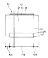
本発明の実施例1は請求項1に対応する実施例であって、図1は本発明の実施例1に係るルーバーガラス11を屋外側から見た場合の斜視図であり、図2はルーバーガラス11が鎧状に重なる際の状態を示す要部断面図である。ルーバーガラス11では、合せガラスの構成になっている合せガラス部15は、ガラス層12の長辺周辺部に形成されており、該ルーバーガラスが鎧状に接触する際の接触側X(図2参照)がガラス層12から成り、反接触側Yが金属層13から成るものであり、ガラス層12と金属層13とが接着材層14を介して向き合う構成になっていて、ガラス層と金属層とが1対1の組み合わせになっており、所謂シングル構造の合せガラスから成るものであって、効果の割にはコストが低廉である。ルーバーガラス11は、接触側がガラス層であるので鎧状に接触する際にはガラス層同士の接触(図2参照)となる。なお、合せガラス部は短辺側にも延長して部分的に設けることができるものであり、その場合は、板状の金属やゴム等から成るスペーサを貼着することによって代用してもよい。
金属層13としては、アルミ押出形材ないしはステンレス鋼板や真鍮板の成形品等から成り、幅が5〜25mm、厚みが0.5〜3mm程度の平板状のものが好ましいが、半筒状ないしは山形状など他の形状であってもよい。接着材層14としては、建築業界においてガラスとサッシとのシールに用いられるシーリング材の類、例えはジメチルポリシロキサンを主成分とするオキシム型であって湿気硬化型の1成分形シリコーン系弾性シーリング材等を用いることができるものであり、引張応力として0.5N/平方ミリメートル前後の大きな接着力を有する。ガラス層12としては、厚み3〜5mmの無色ないしは色彩の型板ガラスやフロートガラス等を用いることができる。
The
ルーバーガラス11では、合せガラス部15は厚み3〜5mmの板ガラスの長辺全長に形成されていて、ガラス層12と接着材層14と金属層13の合計厚みが概ね6.0〜6.8mmの範囲になるように形成されていて6mm用支持金具に適合する形状になっており、従来のルーバー窓において互換性100に用いることができる。また、反接触側Yに配置されている金属層13がガラス層12の外側から先ずは面格子としての機能を果たすものであり、仮に面格子としての機能が及ばずガラス層12が割られた場合においても、周辺部が合せガラスの構成になっていて撓むことがなく、ルーバーガラスが支持金具から抜き取られることはないのであって、金属層が単独に果たす面格子としての機能と、合せガラス部15の本体が果たす合せガラスとしての機能との二段構えの機能によって割り抜き被害は強力に防止される。また、合せガラスの構成になっている箇所は一部であってガラス層の大半は非合せガラスの領域であって厚み3〜5mmの板ガラスが占めており、従来の厚み6.0〜6.8mmに比べて軽量化されている。また、非合わせガラスの領域からは十分な採光が得られる。また、合わせガラス部はルーバー窓の横縞模様を一層強調するものであって美観に優れている。
In the
本発明の実施例2は請求項1と請求項3に対応する実施例であり、図3は本発明の実施例2に係るルーバーガラス21を屋外側から見た場合の正面図である。実施例2における合せガラス部25は、実施例1における合せガラス部15が露出部22bに限定されて形成されている場合であって、支持金具装着部22a、22aには形成されていない。ルーバーガラス21では、合せガラス部25が露出部22bに限定されているので、支持金具装着部22a、22aでは厚みが増加することはなくて元の厚みのままであり、厚み6.0〜6.8mmの板ガラスを用いて合せガラスに構成したルーバーガラスであっても、6mm用支持金具を備えるルーバー窓において互換性100%に用いることができる。即ち、実施例1のルーバーガラス11では厚み3〜5mmの板ガラスに合せガラス部15を形成することによって厚みを増加させて6mm用支持金具に適合させているのに対し、実施例2のルーバーガラス21では合せガラス部25を露出部22bに限定して形成することによって6.0〜6.8mmの板ガラスを用いたルーバーガラスを6mm用支持金具に適合させているのであり、6mm用支持金具に適合するルーバーガラスとしては限度最高のガラス強度を有する。
The second embodiment of the present invention is an embodiment corresponding to
請求項1及び又は請求項3に係る他の実施例としては、図は省略されているが、合せガラス部を側面の一部又は全周囲に設けたシングル構造のルーバーガラスがある。このように、金属層を側面に設ける場合は厚みが増加することはないのであって、6.0〜6.8mm厚の板ガラスを用いた場合にも6mm用支持金具に適合するルーバーガラスが得られる。変形例としては、実施例1における合せガラス部15の構成はルーバー窓以外の窓ガラス、例えば引き違い窓や滑り出し窓等にも適応可能であって、それらの窓における割り破り被害を防止することができる。なお、何れの実施例においても図面は作図上の都合によって金属層や接着材層は実際よりも厚肉に描かれているが、実際は図面から受ける感じよりも薄い存在である。
As another embodiment according to
本発明の実施例3は請求項2に対応する実施例であり、図4は本発明の実施例3に係るルーバーガラス31を屋外側から見た場合の斜視図である。実施例3における合せガラス部35は、実施例1(図1参照)における合せガラス部15の側面Zに対して金属層が追加されて2次元の壁面として形成されている場合であって、ルーバーガラス31が鎧状に接触する際の接触側Xがガラス層32から成り、反接触側Yと側面Zとが金属層33から成るものであり、1つのガラス層と2つの金属層との組み合わせになっていて、所謂ダブル構造の合せガラスから成る。ルーバーガラス31が鎧状に接触する際には実施例1の場合(図2参照)と同様に、ガラス層同士の接触となる。なお、合せガラス部は短辺側にも設けることができるものであり、その場合は、板状お金属やゴム等から成るスペーサによって代用することができる。
Embodiment 3 of the present invention is an embodiment corresponding to claim 2, and FIG. 4 is a perspective view of the
合せガラス部35の反接触側Yと側面Zとを構成する金属層33は、2次元の断面であってL字状を呈しており、アルミ押出形材ないしはステンレス鋼板や真鍮板の成形品等から成り、短辺側は3〜8mm前後、長辺側は5〜30mm前後、厚みは0.5〜2mm前後が好ましい。なお、L字のコナー部は直角である必要はなくて2つの面に沿う形状であれば半筒状など他の形状であってもよい。接着材層34としては実施例1の場合と同じシーリング材を用いることができる。ガラス層32としては厚み3〜5mmの無色ないしは色彩の型板ガラスやフロートガラスを用いることができる。なお、側面Zの金属層とガラス層32との間に介在させる接着材層は省略しても防犯力に支障を来たすことはない。接着材層が省略された側面の金属層はガラス層の側面を覆うカバー材(面格子)として機能するものであって合せガラス部を構成するものではないので、その場合はシングル構造の合せガラスの範疇となる。
The
ルーバーガラス31は、厚みの点では実施例1のルーバーガラス11と同様であって、金属層33と接着材層34とガラス層32との合計厚みが6mm用支持金具に適合する厚みに形成されており、従来のルーバー窓において互換性100%に用いることができる。また、ルーバーガラス31は合せガラス部35がダブル構造になっているので、金属層33が果たす面格子としての機能と、合せガラス部35が果たすそれ本来の機能は共に、実施例1のシングル構造のルーバーガラス11に比べれば単純計算で略2倍に強化されており、撓むことがなく、支持金具から抜き取られることがないのであって、割り抜き被害は更に強力に防止される。また、合せガラスの構成になっている箇所は一部であってガラス層の大半は非合せガラスの領域であって厚み3〜5mmの単板ガラスが占めており、従来の厚み6.0〜6.8mmに比べて軽量化されている。また、非合せガラスの領域からは十分な採光が得られる。また、合わせガラス部はルーバー窓の横縞模様を一層強調するものであって美観に優れている。
The
本発明の実施例4は請求項2と請求項3に対応する実施例であり、図5は本発明の実施例4に係るルーバーガラス41を屋外側から見た場合の正面図である。実施例4における合せガラス部45は、実施例3(図4参照)における合せガラス部35が露出部42bに限定して形成されている場合であって、支持金具装着部42a、42aには形成されていない。ルーバーガラス41では、合せガラス部45が露出部42bに限定して形成されているので、支持金具装着部42a、42aでは厚みが増加することはなくて元の厚みのままであり、厚み6.0〜6.8mmの板ガラスを用いて合せガラスに構成したルーバーガラスであっても、6mm用支持金具を備えるルーバー窓において互換性100%に用いることができる。即ち、実施例3のルーバーガラス31では厚み3〜5mmの板ガラスに合せガラス部35を形成することによって厚みを増加させて6mm用支持金具に適合させているのに対し、実施例4のルーバーガラス41では合せガラス部45を露出部42bに限定して形成することによって6.0〜6.8mmの板ガラスを用いたルーバーガラスを6mm用支持金具に適合させているのであり、6mm用支持金具に適合するルーバーガラスとしては限度最高のガラス強度を有する。
Embodiment 4 of the present invention is an embodiment corresponding to Claims 2 and 3, and FIG. 5 is a front view of the
ルーバーガラス41では、厚み6.0〜6.8mmの板ガラスが用いられていて、ガラス強度が6mm支持金具用としては限度最高であるのみならず、泥棒等侵入者からの攻撃を直接に受ける露出部42bはダブル構造の合せガラスになっていて、実施例1のシングル構造のルーバーガラス11に比べれば単純計算で略2倍の面格子機能と合せガラス機能とを有するものであり、撓むことがなくて、支持金具から抜き取られることがないのであって、割り抜き被害は更に強力に防止される。なお、図5では合せガラス部45を上下双方の長辺に形成した例として示しているが、合せガラス部45は、優先権主張に係る先の出願の請求項3および段落番号0016に記載しているように、上下何れか一方の長辺に形成されていれば十分であり、その場合は下方の長辺に形成するのが好ましい。
In the
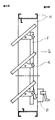
本発明の実施例5は請求項4に対応する実施例であり、図6は本発明の実施例5に係るルーバーガラス41Rの平面図であってロック機構Rが解除されている状態を示しており、図7は図6においてロック機構Rが施錠されている状態を示している。実施例5のルーバーガラス41Rは、図5に示す実施例4のルーバーガラス41にロック機構Rを設けた構成であり、クリップ装着のルーバー窓に専ら用いられるものであって、エンドキャップ装着のルーバー窓は対象としていない。なお、図7に示すルーバーガラス41Rは屋内側から見た場合の正面図であるのに対し、図5に示すルーバーガラス41は屋外側から見た場合の正面図になっている。
Embodiment 5 of the present invention is an embodiment corresponding to claim 4, and FIG. 6 is a plan view of a
ロック機構Rは、合せガラス部45の金属層43の両端部にプレートR1が設けられていて、プレートR1の一端には舌片R2(図7参照)が設けられ、他端に固定用のネジR3が設けられており、舌片R2とネジR3との略中間位置がリベットR4によって金属層43に軸支された構成になっている。ルーバーガラス41Rを支持金具Kに装着する際には、図6に示すように、プレートR1がルーバーガラス41Rに対して略直角の位置、すなわち解除の状態とし、支持金具Kはクリップ部の掛止片K2を矢印K3の方向に開いた状態とし、従来通りの要領で挿入して装着する。ロック機構Rを施錠する際には、プレートR1を矢印R5の方向に回動すると、図7に示すように、クリップ部K1(掛止片K2)が開閉する際の軌道上に舌片R2が出現して、クリップ部K1(掛止片K2)の動きを封ずる位置に至る。しかる後、ネジR3を金属層43に螺入してプレートR1が回動しないように固定する。施錠を解除する際は上記の逆工程となる。なお、金属層43の形状は図示の例ではL字形になっているが、例えば溝形であって板ガラスの全周囲に設けられていてもよい。また、プレートR1は、図示の例では回動させる構成になっているが、スライドさせる等その他の構成であってもよい。
The locking mechanism R is provided with plates R1 at both ends of the
ロック機構Rはルーバーガラスに単独に設けられているので、クリップ装着のルーバー窓のようにロック機能を有しないルーバー窓においても、従来のルーバーガラスから本発明のルーバーガラス41Rに取り替えるのみでロック機能が備わる。このロック機構によって抜き外し被害が防止され、合わせガラス部43によって割り抜き被害が同時に防止される。
Since the lock mechanism R is provided independently on the louver glass, even in a louver window that does not have a lock function, such as a clip-mounted louver window, the lock function can be obtained by simply replacing the conventional louver glass with the
G、11、21、31、41、41R ルーバーガラス
12、22、32、42 ガラス層
13、23、33、43 金属層(層耐衝撃材層)
14、24、34、44 接着材層
15、25、35、45 合せガラス部
X 接触側
Y 非接触側
Z 側面
22a、42a 支持金具装着部
22b、42b 露出部
K 支持金具
K1 クリップ部
K2 掛止片
R ロック機構
R1 プレート
R2 舌片
R3 ネジ
R4 リベット
F 連動フレーム
H 本体部
P オペレータ
G, 11, 21, 31, 41,
14, 24, 34, 44
Claims (4)
Priority Applications (1)
| Application Number | Priority Date | Filing Date | Title |
|---|---|---|---|
| JP2004051229A JP3800341B2 (en) | 2003-09-24 | 2004-02-26 | Louver glass |
Applications Claiming Priority (2)
| Application Number | Priority Date | Filing Date | Title |
|---|---|---|---|
| JP2003330930 | 2003-09-24 | ||
| JP2004051229A JP3800341B2 (en) | 2003-09-24 | 2004-02-26 | Louver glass |
Publications (3)
| Publication Number | Publication Date |
|---|---|
| JP2005120812A JP2005120812A (en) | 2005-05-12 |
| JP2005120812A5 JP2005120812A5 (en) | 2005-09-22 |
| JP3800341B2 true JP3800341B2 (en) | 2006-07-26 |
Family
ID=34621902
Family Applications (1)
| Application Number | Title | Priority Date | Filing Date |
|---|---|---|---|
| JP2004051229A Expired - Fee Related JP3800341B2 (en) | 2003-09-24 | 2004-02-26 | Louver glass |
Country Status (1)
| Country | Link |
|---|---|
| JP (1) | JP3800341B2 (en) |
-
2004
- 2004-02-26 JP JP2004051229A patent/JP3800341B2/en not_active Expired - Fee Related
Also Published As
| Publication number | Publication date |
|---|---|
| JP2005120812A (en) | 2005-05-12 |
Similar Documents
| Publication | Publication Date | Title |
|---|---|---|
| JP4960233B2 (en) | Conservation screen | |
| US7383666B2 (en) | Blast-resistant window | |
| US20180038156A1 (en) | Protective glazing systems, apparatus and methods for structural openings | |
| JP2009511772A (en) | Component | |
| US8590227B2 (en) | Blast-resistant window | |
| WO2015152011A1 (en) | Multilayer panel | |
| EP2339105B1 (en) | Security door comprising an observation window | |
| JP3800341B2 (en) | Louver glass | |
| CN205689066U (en) | A kind of fire resisting door glass pane assembling structure | |
| KR20150020656A (en) | Coupling devices for door frames | |
| JP2007314370A (en) | Stepped laminated glass window | |
| EP3173548A1 (en) | Construction panel corner shield | |
| JPH11280339A (en) | Upper frame construction for insulating sash | |
| JP2014196643A (en) | End face protecting cover for multiplex glass sash, and multiplex glass sash | |
| JP5146244B2 (en) | Entrance door | |
| JP2005155243A (en) | Double glazing door structure | |
| JP5080780B2 (en) | door | |
| JP3974056B2 (en) | Security sash and construction method | |
| JP2005083075A (en) | Glass door | |
| KR102636624B1 (en) | Protecting cover for lower sill of fire door | |
| JP4175533B2 (en) | Seismic door | |
| GB2497358A (en) | A method of framing and installing a viewing panel. | |
| JP4500524B2 (en) | Opening device | |
| GB2403501A (en) | Security glazing | |
| EP3650254B1 (en) | Fixed window of a motor vehicle with opening hatch |
Legal Events
| Date | Code | Title | Description |
|---|---|---|---|
| A521 | Written amendment |
Free format text: JAPANESE INTERMEDIATE CODE: A523 Effective date: 20050629 |
|
| A977 | Report on retrieval |
Free format text: JAPANESE INTERMEDIATE CODE: A971007 Effective date: 20060201 |
|
| A131 | Notification of reasons for refusal |
Free format text: JAPANESE INTERMEDIATE CODE: A131 Effective date: 20060207 |
|
| A521 | Written amendment |
Free format text: JAPANESE INTERMEDIATE CODE: A523 Effective date: 20060309 |
|
| TRDD | Decision of grant or rejection written | ||
| A01 | Written decision to grant a patent or to grant a registration (utility model) |
Free format text: JAPANESE INTERMEDIATE CODE: A01 Effective date: 20060411 |
|
| A61 | First payment of annual fees (during grant procedure) |
Free format text: JAPANESE INTERMEDIATE CODE: A61 Effective date: 20060418 |
|
| R150 | Certificate of patent (=grant) or registration of utility model |
Free format text: JAPANESE INTERMEDIATE CODE: R150 |
|
| FPAY | Renewal fee payment (prs date is renewal date of database) |
Free format text: PAYMENT UNTIL: 20100512 Year of fee payment: 4 |
|
| LAPS | Cancellation because of no payment of annual fees |