JP3795355B2 - Vehicle roof molding - Google Patents
Vehicle roof molding Download PDFInfo
- Publication number
- JP3795355B2 JP3795355B2 JP2001225745A JP2001225745A JP3795355B2 JP 3795355 B2 JP3795355 B2 JP 3795355B2 JP 2001225745 A JP2001225745 A JP 2001225745A JP 2001225745 A JP2001225745 A JP 2001225745A JP 3795355 B2 JP3795355 B2 JP 3795355B2
- Authority
- JP
- Japan
- Prior art keywords
- roof
- lip
- groove
- leg
- head
- Prior art date
- Legal status (The legal status is an assumption and is not a legal conclusion. Google has not performed a legal analysis and makes no representation as to the accuracy of the status listed.)
- Expired - Lifetime
Links
Images


Description
【0001】
【発明の属する技術分野】
本発明は、車体のルーフパネル側縁に沿って前後方向に設けられたルーフ溝に差し込まれて取付けられるルーフモールに関し、更に、詳しくは、ルーフ溝の幅方向に寸法の「ばらつき(一つのルーフ溝で、その長手方向に沿って幅寸法がばらつく場合と、複数の車両間でルーフ溝の幅寸法がばらつく場合との双方を含む)」が生じていても、車体のルーフパネルに対して所定位置に正確に取付けられて、この状態を保持できるルーフモールに関するものである。
【0002】
【従来の技術】
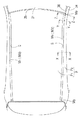
図1は、本発明に係るルーフモールM1 が側縁に取付けられた自動車の車体のルーフパネルPの部分の斜視図であり、図2は、同じく平面図である。図1及び図2に示されるように、ルーフモールM1 は、車体のルーフパネルPの両側縁に沿って車体の前後方向に形成されたルーフ溝G(図5ないし図7参照)に差し込まれて取付けられる。
【0003】
また、ルーフ溝Gの全体形状は、スタイリングの観点から車体パネルの形状、或いは構造によって種々のものがあって、その頂点位置(垂直方向で最も高い位置)Q1(図6ないし図8参照)を基準にして、以下のものがある。(a)車体の前後方向に沿って直線状に伸びるもの。(b)車体の前後方向で端末が滑らかに曲がって、前記頂点位置Q1 よりも下側に位置するもの。(c)車体の前後方向で端末が滑らかに曲がって、かつ前記頂点位置Q1 よりも車体の幅方向で内又は外側に位置するもの。(d)前記(b)と(c)の各形状を組み合わせたもの。(e)更に(d)において、溝の姿勢(水平又は垂直姿勢を基準にして、溝の傾斜、又はねじれ角度)が変化するもの。なお、図1及び図2に示されるルーフモールM1 は、上記(e)で示す形状のルーフ溝に取付けられるものである。
【0004】
図12は、ルーフ溝G’に従来のルーフモールM’を取付けた状態の横断面図である。図12において、ルーフ溝G’は、センタールーフパネルP'1とサイドルーフパネルP'2との接合部に形成される。両パネルP'1, P'2は、金属板をプレス成形したものであって、その幅方向の端末側に段部S'1(S'2) と側壁部SW'1(SW'2) と底壁部BW'1 (BW'2) とが一体に成形されるが、プレス型を使用して金属板をプレス成形するという成形上の特性からして、段部S'1と側壁部SW'1との間の寸法(L1)は、正確に成形できる。
【0005】
しかし、ルーフ溝G’は、両パネルP'1, P'2の各底壁部BW'1, BW'2どうしを重ね合わせて、スポット溶接等で接合して形成される。このため、現在の生産技術水準では、両パネルP'1, P'2を溶接により接合する際の位置ずれ等により、形成されるルーフ溝G’の幅寸法(L2)は、ほぼ1.5〜3mの長さの一つの溝(同一溝)において正規寸法に対してプラス・マイナス1.5mm程度の「ばらつき」が生ずるのは、避けられない。
【0006】
この結果、上記した幅寸法(L2)の「ばらつき」によって、ルーフ溝G’の各段部S'1, S'2の間の寸法(L3)は、前記幅寸法(L2)の「ばらつき」に比例してばらつくことになる。
【0007】
一方、ルーフ溝G’に差し込んで取付けられるルーフモールM’は、合成樹脂の押出成形品であって、その横断面形状は、全長に亘って一定しており、幅広の頭部51と、該頭部51の裏面側から前記ルーフ溝G’に向けて突出するように一体成形された脚部52と、該脚部52の下端部両側からルーフ溝G’の両側壁部SW'1, SW'2に向けて突出する一対の弾発リップ53とを備えている。この一対の弾発リップ53は、左右対称形状をなしている。
【0008】
これにより、ルーフモールM’を構成する一対の弾発リップ53は、ルーフ溝G’の両側壁部SW'1, SW'2に左右振分状態で係止する結果、ルーフモールM’は、常にルーフ溝G’の中心位置に取付けられるという利点がある反面、下記の不具合を包含している。
【0009】
(1)ルーフ溝又はその近傍に、スタイリングの観点及び/ 又はパネルの補強を目的とした段部等がルーフ溝に沿って長手方向に連続して形成されている場合には、モールM’の頭部51の幅方向の端縁51aと、パネル(この場合は、センタールーフパネル)P'1の段部S'1との間の隙間(L4)が、同一溝において長手方向に沿って変動することになる。(2)同一溝の中でルーフ溝G’の幅寸法(L2)が一定に保持されていたとしても、複数の車両の間で前記幅寸法(L2)に「ばらつき」が生ずると、車両毎に前記隙間(L4)が異なることになる。
【0010】
上記した(1),(2)のいずれの不具合が生じても、車両の外観が害される。特に、この不具合は、ルーフ溝の形状が上記した(e)のように、車両の上下方向、幅方向、ねじれ方向の全てにおいて変化するものには、両パネルP'1, P'2の接合作業に複雑さが加わって、顕著に現れる。
【0011】
【発明が解決しようとする課題】
本発明の課題は、ルーフ溝の幅寸法の変動があっても、ルーフ溝の一方の側壁部に対するルーフモールの頭部の前記側壁部の側の幅方向の端縁の位置を不変にして、ルーフモールの取付状態の外観を良好にすることである。
【0012】
【課題を解決するための手段】
上記課題を解決するための請求項1の発明は、車体のルーフパネル側縁に沿って前後方向に設けられたルーフ溝の側壁部に弾発係止して、該ルーフ溝の少なくとも一部を外側から覆うようにして、該ルーフ溝に沿って取付けられる長尺状をした合成樹脂製の車両用ルーフモールであって、前記ルーフモールは前記ルーフ溝の開口部に沿って配置される頭部と、該頭部の裏面側から前記ルーフ溝内に突出するように形成された脚部本体と該脚部本体の下端部の幅方向両側から前記ルーフ溝の両側壁部に向けて各々突出する第1及び第2の脚膨出部とよりなる脚部と、各々の脚膨出部の先端に夫々形成された第1及び第2の各弾発リップとを備え、前記頭部、脚部本体及び脚膨出部は弾性変形可能な剛性を有する合成樹脂から形成され、前記第1及び第2弾発リップはいずれも前記頭部、脚部本体及び脚膨出部よりも軟質でかつ弾力性に富む合成樹脂によって前記脚膨出部に一体的に形成され、両弾発リップの先端の間の距離はフリー状態において前記ルーフ溝の幅よりも広く形成されると共に、第1の弾発リップの弾性復元力は第2の弾発リップの弾性復元力よりも大きくなるように設定され、前記ルーフモールの前記脚部を前記ルーフ溝に押し込んで取り付ける際、前記両側壁部により前記第1及び第2の両方の弾発リップは先端間の距離を短くするように共に弾性変形し、前記ルーフ溝に取り付けられた後には第1弾発リップは実質的に弾性変形せずに長手方向に沿って同一形状を維持し、第2弾発リップはその先端と脚膨出部の突出先端の間に形成されたくびれ部を中心として折れ曲がり状に、長手方向で前記ルーフ溝の溝幅の変動に応じて弾性変形して、両側壁部に対する第2の弾発リップの弾性復元力により前記ルーフ溝内に弾発係止可能とされていることを特徴としている。
【0013】
請求項1の発明によれば、ルーフ溝の幅が変動している場合でも、第2弾発リップがその変動を吸収するため、実質的に弾性変形しない第1弾発リップ側に位置する前記頭部の幅方向の一端縁は、ルーフ溝の全長に亘って、その幅方向に沿って局部的な位置変動を起こすことなく、該ルーフ溝の幅方向に沿って定位置を保って取付けられる。このため、前記隙間がルーフ溝の全長に亘って一定となって、ルーフ溝にモールを取付けた状態における装飾性が低下されない。
【0014】
また、請求項2の発明は、請求項1の発明を前提として、軟質で弾力性に富む材料で成形された前記第1弾発リップは、所定の肉厚と突出長とを有していて、前記第2弾発リップは、その肉厚が前記第1弾発リップの肉厚を超えず、かつその突出長は、前記第1弾発リップの突出長よりも大きく設定されていることを特徴としている。
【0015】
請求項2の発明によれば、第2弾発リップの突出長は、第1弾発リップのそれよりも長くなっているので、ルーフ溝の内壁面から同一の力が作用した場合に、第2弾発リップは、第1弾発リップよりも撓み量が大きくなって、ルーフ溝の溝幅の変動は、第2弾発リップにより吸収される。また、第1及び第2の各弾発リップの突出長に対応したオリフィス形状を有する成形型を使用するのみで、異なる突出長の2本の弾発リップを有するルーフモールの押出成形を容易に行える。
【0016】
【0017】
【0018】
また、請求項3の発明は、請求項1の発明を前提として、軟質で弾力性に富む材質で成形された第1弾発リップは、ルーフ溝の側壁部に対してほぼ直交する方向に向けて突出し、第2弾発リップは、ルーフ溝の別の側壁部に対して略斜め上向きの傾斜方向に向けて突出していることを特徴としている。
【0019】
請求項3の発明によれば、ルーフ溝にモールを取付ける際に、第1弾発リップは、ルーフ溝の側壁部から、その突出方向に押される力を受けるために、変形に対する抗力が生じて、変形しにくくなるのに対して、第2弾発リップは、ルーフ溝の別の側壁部から受ける力によって、曲げモーメントが作用するため、第1弾発リップに比較して、撓み易くなる。このため、ルーフ溝の溝幅の変動は、第2弾発リップにより吸収される。また、第1及び第2の各弾発リップの突出方向に対応したオリフィスを有する成形型を使用するのみで、脚部に対して突出方向の異なる2本の弾発リップを有するルーフモールの押出成形を容易に行える。
【0020】
また、請求項4の発明は、請求項1の発明を前提として、第2弾発リップは、第1弾発リップよりも、更に軟質でかつ弾力性に富む材料から成形されていることを特徴としている。
【0021】
請求項4の発明によれば、第1及び第2の各弾発リップが、ルーフ溝の対向内壁面から同じ力を受けた場合には、第2弾発リップの方が撓み量が大きいので、ルーフ溝の溝幅の変動は、第2弾発リップで吸収される。また、押出成形型に異なる物性の材料を供給して、共押出しすることにより、第1及び第2の各弾発リップが異なる材料で成形されたルーフモールを容易に成形できる。
【0022】
また、請求項5の発明は、請求項1ないし3のいずれかの発明を前提として、第1及び第2の各弾発リップは、軟質で弾力性に富む第1熱可塑性エラストマー樹脂で成形され、頭部、脚部本体及び脚膨出部は、前記第1熱可塑性エラストマー樹脂と相溶性を有し、かつこれよりも硬質で剛性を有する別の第2熱可塑性エラストマー樹脂で成形されて、第1及び第2の各熱可塑性エラストマー樹脂で成形された部分の境界部は溶着一体化していることを特徴としている。
【0023】
請求項5の発明によれば、ルーフモールの頭部及び脚部と、第1及び第2の各弾発リップとの境界部が一体化された状態で、両部分の間において必要な硬度差を設けて成形可能となる。
【0024】
また、請求項6の発明は、請求項1ないし5のいずれかの発明を前提として、頭部の表面には、弾性変形可能で、しかも前記頭部を成形する材料より更に硬質で着色された合成樹脂カバー層が溶着により一体化されていることを特徴としている。
【0025】
請求項6の発明によれば、合成樹脂カバー層の存在により、頭部の長手方向に沿った局部的な曲がり、変形等が生じるのを更に防止すると共に、ルーフモールの耐表面損傷性が向上して、耐久性が増す。
【0026】
また、請求項7の発明は、請求項1ないし6のいずれかの発明を前提として、頭部を構成する材料よりも更に硬質で剛性を有する材料からなる板状の補強部材が、前記頭部及び/ 又は脚部本体の幅方向の中心部に、その面が前記頭部の幅方向と非平行となる姿勢を保持して埋設されていることを特徴としている。
【0027】
請求項7の発明によれば、ルーフパネル側縁に設けられるルーフ溝は、その前後方向に沿って三次元的にわん曲していることが多く、補強部材が上記のようにして埋設されることより、ルーフモールは、前記補強部材の面に対して垂直な面内においてわん曲され易くなるために、無理に変形されることなく、ルーフ溝の形状に倣って自然に取付けることが可能となる。これにより、ルーフ溝の形状に倣って、モール全体が無理なくわん曲させられて、第1及び第2の各弾発リップに溝幅方向に沿って無理な荷重が作用しなくなって、第1及び第2の各弾発リップが本来有している上記特性が阻害されなくなる。
【0028】
【発明の実施の形態】
以下、実施形態を挙げて本発明を更に詳細に説明する。図3は、本発明に係る車両用ルーフモールM1 の斜視図であり、図4は、同じく拡大横断面図であり、図5は、図1及び図2のX−X線断面図であり、図6は、図1及び図2のY−Y線断面図であり、図7は、図1及び図2のZ−Z線断面図であり、図8は、ルーフ溝GにルーフモールM1 を差し込んでいる途中を示す横断面図であり、図9は、同じく差し込まれた状態の横断面図(図5の部分拡大図)である。
【0029】
ルーフモールM1 が取付けられるルーフ溝Gの全体形状は、「従来の技術」の項目で説明したように、図1及び図2のX−X線位置である頂点位置Q1 を基準にして、その前後方向の端末が滑らかに曲がって、前記頂点位置Q1 よりも下側に位置し、しかもルーフ溝Gが車体の幅方向で外側に位置しており、これに加えて、その全体が捩じられた形状となっている。なお、図5ないし図7において、一点鎖線で示される曲線Cは、それぞれ図1及び図2のX−X線位置においてルーフ溝Gの中心(取付けられたルーフモールM1 の補強部材6が位置する点)を背面側から見た曲線を示し、各図において、Q2 は、ルーフ溝Gの前端位置を示す。
【0030】
また、図9に示されるように、ルーフ溝Gは、金属板をプレス成形したセンタールーフパネルP1 とサイドルーフパネルP2 との接合部に形成されて、センタールーフパネルP1 の側の段部S1 は、ルーフ溝GにルーフモールM1 が取付けられた状態で、その頭部1の表面(装飾面)とセンタールーフパネルP1 の表面とが無段差状態となるように、浅く形成されているが、サイドルーフパネルP2 の段部S2 は、ルーフ溝GにルーフモールM1 が取付けられた状態で、なお前記段部S2 の大部分が残存している程の高低差を有している。よって、ルーフモールM1 の幅方向の両端縁と、各段部S1,S2 との間の各隙間に関しては、頭部1の表面とルーフパネルPの表面とがほぼ無段差状態となっている頭部1の内側の端縁とセンタールーフパネルP1 との間の隙間(L4)に変化のある場合の方が、取付状態の外観が悪くなる。
【0031】
また、ルーフ溝Gは、両パネルP1,P2 の各側壁部SW1,SW2 と各底壁部BW1,BW2 とによって横断面が緩やかな台形状に形成されている。即ち、ルーフ溝Gの入口開口21の幅(L2)〔図8参照〕は、その「ばらつき」を考慮しても(「ばらつき」により最大幅となっても)、ルーフモールM1 の頭部1の幅(L11) 〔図4及び図8参照〕よりも狭く形成されている。また、ルーフ溝Gの溝幅は、その全体形状が緩やかな台形状になっていることからして、入口開口21から底部に向けて徐々に広くなっているが、その「ばらつき」を考慮しても(「ばらつき」により最大幅となっても)、ルーフモールM1 の第1及び第2の各弾発リップ3,4が係止される部分の幅は、フリー状態(自然状態)における各弾発リップ3,4の先端の間の長さ(L12)〔図4参照〕よりも狭くなっている。
【0032】
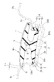
また、図3及び図4において、ルーフモールM1 は、ルーフ溝Gの入口開口21に臨む部分に配置されて、センター側及びサイド側の各段部S1,S2 の底面22(図8参照)に弾接する頭部1と、該頭部1の裏面側から前記ルーフ溝G内に突出するように形成された脚部2と、該脚部2の下端部の両側から、前記ルーフ溝Gの両側壁部SW1,SW2 に向けて各々突出する第1及び第2の各弾発リップ3,4との3つの部分で構成される。
【0033】
また、前記脚部2は、前記頭部1の幅方向の中央部に一体成形された脚部本体2aと、該脚部本体2aの下半部の両側に各々側方に向けて突出された第1及び第2の各脚膨出部2b,2cとの3つの部分で構成される。前記第1弾発リップ3は、センター側に配置された第1脚膨出部2bの先端部に一体成形されて、センター側の側壁部SW1 に係止されると共に、第2弾発リップ4は、サイド側に配置された第2脚膨出部2cの先端部に一体成形されて、サイド側の側壁部SW2 に係止される。
【0034】
ここで、第1及び第2の各弾発リップ3,4の形状について、更に詳細に述べる。センター側に配置される第1弾発リップ3は、脚部2を構成する第1脚膨出部2bの先端部に、ほぼ水平方向に突出して一体成形された基部3aと、該基部3aの先端部にくびれ部3cを介して斜上方を向いて成形された係止部3bとで構成される。即ち、第1弾発リップ3を構成する基部3aと係止部3bとは、上方に向けて鈍角状に屈曲されていて、前記係止部3bの肉厚は、前記基部3aの肉厚よりも薄く成形されていると共に、前記係止部3bの長さは、前記基部3aの長さよりも短く成形されている。
【0035】
一方、サイド側に配置される第2弾発リップ4は、脚部2を構成する第2脚膨出部2cの先端部に、ほぼ水平方向に突出して一体成形された基部4aと、該基部4aの先端部にくびれ部4cを介して斜上方を向いて成形された係止部4bとで構成される。即ち、第2弾発リップ4を構成する基部4aと係止部4bとは、前記第1弾発リップ3と同様にして、上方に向けて鈍角状に屈曲されているが、第2弾発リップ4の全長(L13) は、第1弾発リップ3の全長(L14) 〔いずれも図4参照〕よりも長くなっている。また、第1弾発リップ3は、基部3aの長さが係止部3bよりも長くなっているのに対して、第2弾発リップ4は、前記第1弾発リップ3とは逆に、基部4aの長さが係止部4bの長さよりも短くなっている。このように、第2弾発リップ4は、第1弾発リップ3よりも長く成形され、しかも、これを構成する基部4a(3a)と係止部4b(3b)との長さの関係が逆となっているので、第2弾発リップ4は、幅方向の内側に向く力が作用したときに、第1弾発リップ3に比較して、くびれ部4cを中心にして変形し易くなっている。
【0036】
また、第1及び第2の各弾発リップ3,4は、全体としてはルーフ溝Gの各側壁部SW1,SW2 に対しては、いずれもほぼ直交した方向に向けて突出している。
【0037】
また、図7に示されるように、ルーフモールM1 の長手方向の両端部の所定長の部分には、別のクリップ等の取付具を取付可能にするために、脚部2、並びに第1及び第2の各弾発リップ3,4は、除去されて形成されていない。このため、図7に示されるように、ルーフモールM1 の長手方向の両端部においては、その頭部1のみが両段部S1,S2 の底面22に接している。なお、図1及び図2において、Ma,Mb は、それぞれルーフモールM1 の前端部及び後端部を示す。
【0038】
また、前記頭部1及び脚部2を成形する合成樹脂は、第1及び第2の各弾発リップ3,4を成形する樹脂よりも硬質で、しかも剛性を有するものであれば、特に限定されないが、好ましくは、ショアA硬度で55〜90度程度の範囲に入る半硬質塩化ビニール樹脂、ポリプロピレン樹脂、或いは熱可塑性エラストマー樹脂(オレフィン系、スチレン系、ビニール系等)等が挙げられる。上記実施形態では、頭部1及び脚部2は、いずれも上記合成樹脂で成形されているが、各部分において樹脂の種類が異なっている。
【0039】
一方、第1及び第2の各弾発リップ3,4を成形する合成樹脂は、前記頭部1及び脚部2を成形する樹脂よりも軟質であって、しかもゴム状弾性を呈する樹脂で成形され、好ましくは、ショアA硬度で40〜80度程度の範囲に入る熱可塑性エラストマー樹脂(オレフィン系、スチレン系、ビニール系等)が挙げられる。ここで、第1及び第2の各弾発リップ3,4を成形する合成樹脂は、いずれも上記条件を満たしていることを前提として、第2弾発リップ4は、第1弾発リップ3よりも、軟質で、しかも弾性に富む樹脂で成形して、成形原料である樹脂自体の相違によって、第2弾発リップ4を第1弾発リップ3よりも弾性変形し易くすることが好ましい。これにより、第2弾発リップ4は、第1弾発リップ3に比較して、上記した形状的に変形し易いのに加えて、成形原料の差異が原因となって変形し易くもなっていて、本発明の目的が達成し易くなる。
【0040】
ただし、本発明においては、頭部1、脚部2、並びに第1及び第2の各弾発リップ3,4を構成する樹脂の硬度は、上記した数値に限定されるものではなく、前記各弾発リップ3,4を構成する合成樹脂が、前記頭部1及び脚部2を構成する合成樹脂よりも軟質で、しかも弾力性に富むものであれば、いかなる樹脂であっても選択可能である。
【0041】
また、ルーフモールM1 を構成する頭部1の表面には、該頭部1を構成する合成樹脂よりも硬質であって、しかも着色された合成樹脂からなるカバー層5が溶着により一体化されている。このカバー層5の存在によって、頭部1のルーフ溝Gの方向に沿った局部的な曲がり、同変形等が生じるのを防止できると共に、ルーフモールM1 の表面が傷付けられるのを防止でき、しかも外観も良好となる。
【0042】
また、頭部1の幅方向の中央部の最も肉厚の大きな部分には、金属帯板から成る補強部材6が、その面が前記頭部1の幅方向と非平行となる姿勢を維持して埋設されている。即ち、実施形態では、補強部材6は、帯板の幅方向端部のサイド側がセンター側よりも高くなるように傾斜してルーフモールM1 の頭部1に埋設されて、該補強部材6の上面は、車体を基準にすると、その表面は、車体の斜上側方を向いている。これにより、ルーフモールM1 の全体は、前記補強部材6の板面に対して垂直な面内において変形し易くなって、全体がねじられた形状になっている前記ルーフ溝Gの全体形状に対応して、該ルーフ溝Gの形状に倣って前記ルーフモールM1 がわん曲され易くなっていて、該ルーフ溝Gに対するルーフモールM1 の取付けを容易にしている。
【0043】
また、前記ルーフモールM1 は、頭部1の表面にカバー層5が一体に溶着された状態で連続押出成形され、ルーフ溝Gの長さに対応した長さに切断して、その両端部において所定長の脚部2、並びに第1及び第2の各弾発リップ3,4を切除した後に、別途の取付具を取付けて使用する。そして、押出成形型に関しては、成形されるルーフモールM1 の横断面形状に対応した押出成形口(オリフィス)を有するものを使用して、各成形部分毎に異なる成形原料(溶融合成樹脂)を供給して、共押出しにより成形する。
【0044】
そして、ルーフパネルPの両側縁に前後方向に沿って設けられたルーフ溝Gに前記ルーフモールM1 を差し込んで取付けるには、以下のようにして行う。まず、図8に示されるように、ルーフモールM1 の脚部2をルーフ溝Gの入口開口21に当てがった状態で、その頭部1に、ルーフ溝Gの底壁部BW1(BW2)に対して垂直な方向の押付け力Fを加えると、第1及び第2の各弾発リップ3,4がそれぞれルーフ溝Gの段部S1,S2 に当たって、各弾発リップ3,4は、いずれもくびれ部3c,4c を中心にして上方に向けて弾性変形して、弾性変形後の各弾発リップ3,4の先端の間の距離が前記入口開口21の幅(L2)と等しくなった状態で、ルーフモールM1 の脚部2は、ルーフ溝G内に押し込まれる。
【0045】
また、ルーフ溝G内にルーフモールM1 の脚部2が押し込まれると、ルーフ溝Gを基準にしてセンター側に配置された第1弾発リップ3は、弾性変形してほぼ元の形状に戻り、後述する第2弾発リップ4の反力によりセンター側の側壁部SW1 に弾接して、脚部2を第2弾発リップ4の側(サイド側)に押し付ける。一方、サイド側に配置された第2弾発リップ4は、弾性変形してサイド側の側壁部SW2 に弾接して、元に戻ろうとする弾性復元力により、脚部2を第1弾発リップ3の側(センター側)に押し付ける。
【0046】
ここで、上記したように、第1弾発リップ3は、第2弾発リップ4に比較して形状的、及び構成材料の双方からして弾性変形しにくい構造(同一量だけ弾性変形するのに、第2弾発リップ4よりも大きい力を必要とする構造)にしてあるので、第1弾発リップ3の弾性復元力は、第2弾発リップ4のそれに比較して相対的に大きくなる。よって、図9に示されるように、ルーフモールM1 の脚部2がルーフ溝Gに差し込まれた後には、第1弾発リップ3は、元の形状に復元して実質的に弾性変形せずに、第2弾発リップ4のみが弾性変形した状態となって、当該状態が維持される。
【0047】
そして、図10に示されるように、ルーフ溝Gの長手方向において、その溝幅(L2)が変化した場合には、この変化に追随して、変形し易い第2弾発リップ4のみが弾性変形して、前記溝幅の変化を吸収する構造となる。即ち、ルーフ溝Gの溝幅(L'2) が基準溝幅(L2)よりも広くなった場合には、第2弾発リップ4は、基準溝幅(L2)における弾性変形量よりも少ない量だけ弾性変形した状態が維持されると共に、ルーフ溝Gの溝幅(L"2) が基準溝幅(L2)よりも狭くなった場合には、第2弾発リップ4は、基準溝幅(L2)における弾性変形量よりも多い量だけ弾性変形した状態が維持される。
【0048】
この結果、ルーフ溝Gのセンター側の側壁部SW1 に対するルーフモールM1 の頭部1の第1弾発リップ3の側の幅方向端位置は、殆ど不変となって、センター側の前記隙間(L4)は、一定寸法を維持することになる。これに対して、一対の弾発リップをバランスさせてルーフ溝の中央部に配置する従来構造のルーフモールM’では、ルーフ溝Gの溝幅の変化に応じて、前記隙間(L4)が変動することになる。
【0049】
なお、図1及び図2において、31は、フロントウインドウであり、32は、フロントドアであり、33は、リアドアであり、34は、フロントピラーパネルであり、35は、ウインドウアッパーモールであり、36は、ウインドウサイドモールである。
【0050】
また、ルーフモールM1 の頭部1に埋設された板状をした補強部材6は、その面が前記頭部1の幅方向と非平行となる姿勢を維持して埋設されているので、捩じられた形状のルーフ溝Gに対しても前記ルーフモールM1 を対応形状に変形させて、無理なく取付けることができる。このため、第1及び第2の各弾発リップ3,4に溝幅方向に沿って無理な荷重が作用しなくなって、第1及び第2の各弾発リップ3,4の本来有している上記特性が阻害されなくなる。
【0051】
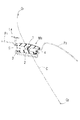
また、図11は、本発明の別のルーフモールM2 がルーフ溝Gに取付けられた状態の横断面図である。このルーフモールM2 を構成する第1及び第2の各弾発リップ3',4’の全体形状は、前記ルーフモールM1 の各弾発リップ3,4とほぼ同一形状であって、その屈曲部も上面に設けられているが、ルーフモールM2 は、前記ルーフモールM1 に対してルーフ溝Gの両側壁部SW1,SW2 に対する突出方向が異なる。即ち、第1弾発リップ3’は、これが係止される側壁部SW1 に対してほぼ直交する方向に突出しているが、第2弾発リップ4’は、これが係止される側壁部SW2 に対して非直交となる傾斜方向に突出している。
【0052】
このため、ルーフ溝GにルーフモールM2 を取付ける際に、第1弾発リップ3’は、その突出方向の関係からして、ルーフ溝Gの側壁部SW1 から、その突出方向に押される力を受けるために、変形に対する抗力が生じて、変形しにくくなる。これに対して、第2弾発リップ4’は、その突出方向の関係からして、ルーフ溝の別の側壁部SW2 から受ける力によって、上方に向けてわん曲するような曲げモーメントが作用するために、第1弾発リップ3’に比較して撓み易くなる。このように、ルーフモールM2 を構成する各弾発リップ3',4’のルーフ溝Gの各側壁部SW1,SW2 に対する突出方向に差を設けることにより、一方の弾発リップ4’をより変形し易くできて、本発明の上記課題が達成され易くなる。
【0053】
また、本発明が実施可能なルーフモールは、上記実施形態のように、その頭部1によってルーフ溝Gが全幅に亘って覆われるものに限定されず、ルーフ溝の幅方向の少なくとも一部を覆っていて、一方の側壁部との間に上方に向けて開口する流水溝を形成する構成のものに対しても実施可能である。更に、頭部の形状に関しても、上記実施形態のように、その幅方向で左右対称である必要はなく、非対称であっても、頭部における第1弾発リップの側の幅方向端位置が、ルーフ溝における前記第1弾発リップの側の側壁部に対して一定位置を維持していれば、頭部の形状自体は、いかなるものであってもよい。
【0054】
また、第1及び第2の各弾発リップの位置は、センター側又はサイド側のいずれのパネルとの隙間を一定に保持するかによって異なるもので、前述の実施形態と異なることもある。
【0055】
また、上記実施形態は、ねじれを含んだ最も複雑な形状のルーフ溝Gを有する車両に対して本発明を実施したものであるが、「従来の技術」の項目で説明した(a)〜(d)に示される形状のルーフ溝を有する車両に対しても実施可能である。
【0056】
【発明の効果】
本発明は、ルーフモールの脚部の両側に設けられる第1及び第2の各弾発リップに弾性復元力に大きな差を設けてあって、ルーフ溝にルーフモールを取付けた状態において、一方の弾発リップは、殆ど弾性変形しないで、ルーフ溝の側壁部に係止する構造にしてあるので、ルーフ溝の幅寸法の変動があっても、ルーフ溝の一方の側壁部に対するルーフモールの頭部の前記側壁部の側の幅方向の端縁の位置を不変にして、ルーフモールの取付状態の外観が良好となる。
【図面の簡単な説明】
【図1】 本発明に係るルーフモールM1 が側縁に取付けられた自動車の車体のルーフパネルPの部分の斜視図である。
【図2】 同じく平面図である。
【図3】 本発明に係る車両用ルーフモールM1 の斜視図である。
【図4】 同じく拡大横断面図である。
【図5】 図1及び図2のX−X線断面図である。
【図6】 図1及び図2のY−Y線断面図である。
【図7】 図1及び図2のZ−Z線断面図である。
【図8】 ルーフ溝GにルーフモールM1 を差し込んでいる途中を示す横断面図である。
【図9】 同じく差し込まれた状態の横断面図(図5の部分拡大図)である。
【図10】 ルーフ溝Gの溝幅の変化に対する第2弾発リップ4の変形状態の変化を示す部分拡大断面図である。
【図11】 本発明に係る別のルーフモールM2 がルーフ溝Gに取付けられた状態の横断面図である。
【図12】 ルーフ溝G’に従来のルーフモールM’を取付けた状態の横断面図である。
【符号の説明】
BW1,BW2 :ルーフ溝の底壁部
G:ルーフ溝
L4 :隙間
M1,M2 :ルーフモール
P:ルーフパネル
P1 :センタールーフパネル
P2 :サイドルーフパネル
S1,S2 :段部
SW1,SW2 :ルーフ溝の側壁部
1:頭部
2:脚部
2a:脚部本体
2b:第1脚膨出部
2c:第2脚膨出部
3:第1弾発リップ
4:第2弾発リップ
4c:第2弾発リップのくびれ部
5:カバー層
6:補強部材[0001]
BACKGROUND OF THE INVENTION
The present invention relates to a roof molding that is attached by being inserted into a roof groove provided in the front-rear direction along the side edge of the roof panel of the vehicle body. Even if the width dimension of the groove varies along the longitudinal direction of the groove and the width dimension of the roof groove varies among a plurality of vehicles) The present invention relates to a roof molding that can be accurately attached to a position and maintain this state.
[0002]
[Prior art]
FIG. 1 shows a roof molding M according to the present invention.1FIG. 2 is a perspective view of a portion of a roof panel P of a vehicle body attached to a side edge, and FIG. 2 is a plan view of the same. As shown in FIGS. 1 and 2, the roof molding M1Is inserted and attached to a roof groove G (see FIGS. 5 to 7) formed in the longitudinal direction of the vehicle body along both side edges of the roof panel P of the vehicle body.
[0003]
Also, the overall shape of the roof groove G varies depending on the shape or structure of the vehicle body panel from the viewpoint of styling, and its apex position (the highest position in the vertical direction) Q1Based on (see FIGS. 6 to 8), there are the following. (A) Those extending linearly along the longitudinal direction of the vehicle body. (B) The terminal bends smoothly in the longitudinal direction of the vehicle body, and the vertex position Q1The one that is located below. (C) The terminal bends smoothly in the front-rear direction of the vehicle body and the vertex position Q1It is located inside or outside in the width direction of the car body. (D) A combination of the shapes of (b) and (c). (E) Further, in (d), the groove posture (the inclination of the groove or the twist angle with respect to the horizontal or vertical posture) is changed. The roof molding M shown in FIGS. 1 and 21Is attached to the roof groove having the shape shown in (e) above.
[0004]
FIG. 12 is a cross-sectional view of a state where a conventional roof molding M ′ is attached to the roof groove G ′. In FIG. 12, the roof groove G ′ has a center roof panel P ′.1And side roof panel P '2And is formed at the junction. Both panels P '1, P '2Is formed by press-molding a metal plate, and has a stepped portion S ′ on the end side in the width direction.1(S '2) And side wall SW '1(SW '2) And bottom wall BW '1 (BW '2) Is formed as a single piece, but from the viewpoint of the molding characteristics of pressing a metal plate using a press die, the step S ′1And side wall SW '1Dimension between and (L1) Can be molded accurately.
[0005]
However, the roof groove G ′ is formed on both panels P ′.1, P '2Each bottom wall BW '1, BW '2They are formed by overlapping each other and joining them by spot welding or the like. Therefore, at the current production technology level, both panels P '1, P '2The width dimension (L of the roof groove G 'formed due to misalignment or the like when joining2) Is inevitable that a variation of about plus or minus 1.5 mm with respect to the normal dimension occurs in one groove (same groove) having a length of about 1.5 to 3 m.
[0006]
As a result, the width dimension (L2) Of each step S ′ of the roof groove G ′.1, S '2Dimension between (LThree) Is the width dimension (L2) Varies in proportion to the "variation".
[0007]
On the other hand, the roof molding M ′ that is attached by being inserted into the roof groove G ′ is an extruded product of a synthetic resin, and the cross-sectional shape thereof is constant over the entire length, and the
[0008]
As a result, the pair of
[0009]
(1) When a step for the purpose of styling and / or reinforcing the panel is continuously formed in the longitudinal direction along the roof groove at or near the roof groove, An
[0010]
Even if any of the above problems (1) and (2) occurs, the appearance of the vehicle is damaged. In particular, the problem is that both the panels P ′ are used when the roof groove shape changes in all of the vertical direction, the width direction, and the torsional direction of the vehicle as shown in (e) above.1, P '2Adds complexity to the joining work, and it appears prominently.
[0011]
[Problems to be solved by the invention]
The problem of the present invention is that even if there is a variation in the width dimension of the roof groove, the position of the edge in the width direction on the side of the side wall portion of the roof molding head relative to one side wall portion of the roof groove is unchanged, The appearance of the roof molding installationGoodIs Rukoto.
[0012]
[Means for Solving the Problems]
According to a first aspect of the present invention for solving the above problem, at least a part of the roof groove is elastically locked to a side wall portion of a roof groove provided in the front-rear direction along the side edge of the roof panel of the vehicle body. It is a roof molding for a vehicle made of a synthetic resin having a long shape attached along the roof groove so as to cover from the outside,The roof molding isAt the opening of the roof grooveAlongThe head portion to be disposed and the leg portion formed so as to protrude into the roof groove from the back side of the head portionBodyAnd the legBodyAt the bottom ofWidth directionFirst and second protrusions projecting from both sides toward both side walls of the roof grooveThe leg part which becomes a leg bulge part, and the 1st and 2nd respectively formed in the front-end | tip of each leg bulge partEach bullet lip and the head, Leg body and leg bulgeFormed of a synthetic resin having elastically deformable rigidity, the first and first2 bulletsLip fromYesMisalignment of the head, Leg body and leg bulgeSofter thanAndWith a highly flexible synthetic resinFormed integrally with the leg bulge,The distance between the ends of the bullet lipIsMore than the width of the roof groove in the free stateWideFormedAnd the elastic restoring force of the first bullet lip is set to be larger than the elastic restoring force of the second bullet lip,Push the leg into the roof grooveWhen installing,in frontThe first and second walls by the side wallsBothBullet lipIs between the tipsTo shorten the distanceAfter both elastically deformed and attached to the roof grooveThe first lip is essentiallyElasticityThe same shape along the longitudinal direction without deformationMaintainThe second lip isBends around the constriction formed between the tip and the protruding tip of the leg bulgeAccording to the variation of the groove width of the roof groove in the longitudinal directionBulletSexually deformed against both side wallsSecondElasticity of bullet lipRestoreBy forceSaidBullet locking in the roof groovePossibleIt is characterized by being.
[0013]
According to the first aspect of the present invention, even when the width of the roof groove is fluctuating, the second bullet lip absorbs the fluctuation, so that the first bullet lip that is not substantially elastically deformed is located on the side. One end edge in the width direction of the head is attached to the roof groove in a fixed position along the width direction of the roof groove without causing a local position variation along the width direction of the roof groove. . For this reason, the said clearance gap becomes constant over the full length of a roof groove | channel, and the decorativeness in the state which attached the molding to the roof groove | channel is not deteriorated.
[0014]
According to a second aspect of the present invention, on the premise of the first aspect of the invention, the first elastic lip molded from a soft and elastic material has a predetermined thickness and a protruding length. The second bullet lip has a wall thickness that does not exceed the wall thickness of the first bullet lip, and the projection length is set to be larger than the projection length of the first bullet lip. It is a feature.
[0015]
According to the invention of
[0016]
[0017]
[0018]
Claims3According to the present invention, on the premise of the invention of
[0019]
Claim3According to the invention, when the molding is attached to the roof groove, the first resilient lip receives a force pushed in the protruding direction from the side wall portion of the roof groove, and therefore, the resistance against deformation is generated and the first lip is deformed. In contrast, the second bullet lip is more easily bent than the first bullet lip because a bending moment acts on the second bullet lip due to a force received from another side wall portion of the roof groove. For this reason, the fluctuation of the groove width of the roof groove is absorbed by the second bullet lip. Further, only by using a mold having an orifice corresponding to the projecting direction of each of the first and second projecting lips, the extrusion of the roof molding having two projecting lips with different projecting directions with respect to the leg portion is performed. Easy to form.
[0020]
Claims4According to the present invention, on the premise of the invention of
[0021]
Claim4According to the invention, when each of the first and second bullet lips receives the same force from the opposing inner wall surface of the roof groove, the second bullet lip has a larger amount of deflection, so the roof groove The fluctuation of the groove width is absorbed by the second bullet lip. Also, by supplying materials having different physical properties to the extrusion mold and co-extrusion, the roof molding in which the first and second elastic lips are formed of different materials can be easily formed.
[0022]
Claims5The invention of
[0023]
Claim5According to the invention, in the state where the boundary between the head and legs of the roof molding and the first and second bullet lips is integrated, a necessary hardness difference is provided between the two parts. Molding becomes possible.
[0024]
Claims6The invention of
[0025]
Claim6According to the invention, the presence of the synthetic resin cover layer further prevents local bending, deformation, etc. along the longitudinal direction of the head, and improves the surface damage resistance of the roof molding, Increased durability.
[0026]
Claims7The invention of
[0027]
Claim7According to the invention, the roof groove provided on the side edge of the roof panel is often bent three-dimensionally along the front-rear direction, and the reinforcing member is embedded as described above. Since the roof molding is easily bent in a plane perpendicular to the surface of the reinforcing member, the roof molding can be naturally attached according to the shape of the roof groove without being forcibly deformed. As a result, the entire molding is bent without difficulty according to the shape of the roof groove, and an unreasonable load does not act on the first and second bullet lips along the groove width direction. And the said characteristic which each 2nd bullet lip originally has will not be inhibited.
[0028]
DETAILED DESCRIPTION OF THE INVENTION
Hereinafter, the present invention will be described in more detail with reference to embodiments. FIG. 3 shows a vehicle roof molding M according to the present invention.14 is an enlarged cross-sectional view, FIG. 5 is a cross-sectional view taken along the line XX of FIGS. 1 and 2, and FIG. 6 is a YY view of FIGS. 7 is a cross-sectional view taken along the line ZZ in FIGS. 1 and 2, and FIG.1FIG. 9 is a cross-sectional view (partially enlarged view of FIG. 5) in a state where the same is inserted.
[0029]
Roof Mall M1The overall shape of the roof groove G to which the frame is mounted is the vertex position Q, which is the XX line position in FIGS. 1 and 2, as described in the section “Prior Art”.1, The terminal in the front-rear direction bends smoothly, and the vertex position Q1Further, the roof groove G is located outside in the width direction of the vehicle body, and in addition to this, the entire shape is twisted. 5 to 7, the curve C indicated by the alternate long and short dash line indicates the center of the roof groove G (the attached roof molding M at the XX line position in FIGS. 1 and 2, respectively.1The point where the reinforcing
[0030]
Further, as shown in FIG. 9, the roof groove G has a center roof panel P formed by press-molding a metal plate.1And side roof panel P2Center roof panel P1Step S on the side of1Is the roof molding G in the roof groove G1Is attached to the surface (decorative surface) of the
[0031]
Moreover, the roof groove G is formed on both panels P.1, P2Each side wall SW of1, SW2And each bottom wall BW1, BW2Are formed in a trapezoidal shape with a gentle cross section. That is, the width of the entrance opening 21 of the roof groove G (L2) [Refer to FIG. 8], even if the “variation” is taken into account (even if the maximum width is caused by the “variation”), the roof molding M1Width of head 1 (L11) Narrower than [see FIGS. 4 and 8]. Further, the groove width of the roof groove G is gradually widened from the inlet opening 21 to the bottom because the overall shape is a gentle trapezoidal shape. Even (even if it becomes the maximum width due to "variation"), the roof molding M1The width of the portion where the first and
[0032]
3 and 4, the roof molding M1Is arranged at a portion facing the entrance opening 21 of the roof groove G, and each step S on the center side and the side side is provided.1, S2A
[0033]
The
[0034]
Here, the shape of each of the first and
[0035]
On the other hand, the second projecting
[0036]
Further, the first and second
[0037]
In addition, as shown in FIG.1The
[0038]
The synthetic resin for molding the
[0039]
On the other hand, the synthetic resin for molding each of the first and second
[0040]
However, in the present invention, the hardness of the resin constituting the
[0041]
Roof Mall M1The
[0042]
Further, a reinforcing
[0043]
The roof molding M1Are continuously extruded with the
[0044]
Then, the roof molding M is formed in the roof groove G provided on both side edges of the roof panel P along the front-rear direction.1To insert and install, do as follows. First, as shown in FIG.1In the state where the
[0045]
Also, in the roof groove G, the roof molding M1When the
[0046]
Here, as described above, the
[0047]
Then, as shown in FIG. 10, in the longitudinal direction of the roof groove G, the groove width (L2) Changes, only the
[0048]
As a result, the side wall SW on the center side of the roof groove G1Roof Mall M against1The width direction end position of the
[0049]
1 and 2, 31 is a front window, 32 is a front door, 33 is a rear door, 34 is a front pillar panel, and 35 is a window upper molding. 36 is a window side molding.
[0050]
Roof Mall M1The plate-shaped reinforcing
[0051]
FIG. 11 shows another roof molding M of the present invention.2FIG. 4 is a transverse cross-sectional view of a state where is attached to the roof groove G. This roof mall M2The overall shape of each of the first and second bullet lips 3 'and 4' constituting the roof molding M1Each of the
[0052]
For this reason, the roof molding M in the roof groove G2When the first lip 3 'is attached, the side wall SW of the roof groove G is taken into account in relation to the protruding direction.1Therefore, in order to receive the force pushed in the protruding direction, a resistance against deformation is generated, and the deformation becomes difficult. On the other hand, the second bullet lip 4 'has another side wall portion SW of the roof groove in view of the projecting direction.2Since the bending moment that bends upward acts by the force received from the first, it becomes easier to bend compared to the first bullet lip 3 '. In this way, roof molding M2Each side wall SW of the roof groove G of each bullet lip 3 ', 4' constituting1, SW2By providing a difference in the protruding direction with respect to, one of the
[0053]
Further, the roof molding in which the present invention can be implemented is not limited to one in which the roof groove G is covered over the entire width by the
[0054]
Further, the positions of the first and second bullet lips differ depending on whether the gap with the center side panel or the side panel is kept constant, and may differ from the above-described embodiment.
[0055]
Moreover, although the said embodiment implements this invention with respect to the vehicle which has the roof groove | channel G of the most complicated shape containing a twist, (a)-( It can also be applied to a vehicle having a roof groove having the shape shown in d).
[0056]
【The invention's effect】
The present invention is elastic to the first and second elastic lips provided on both sides of the leg portion of the roof molding.RestoreThere is a large difference in force, and in the state where the roof molding is attached to the roof groove, one resilient lip is structured to be locked to the side wall of the roof groove with almost no elastic deformation. Even if the width of the groove changes, the position of the edge of the roof molding head on the side of the side of the roof molding relative to one side of the roof groove remains unchanged, and the appearance of the roof molding installation stateIs good.
[Brief description of the drawings]
FIG. 1 is a roof molding M according to the present invention.1It is a perspective view of the part of the roof panel P of the vehicle body of the motor vehicle attached to the side edge.
FIG. 2 is also a plan view.
FIG. 3 is a vehicle roof molding M according to the present invention.1FIG.
FIG. 4 is an enlarged cross-sectional view of the same.
5 is a cross-sectional view taken along the line XX in FIGS. 1 and 2. FIG.
6 is a cross-sectional view taken along the line YY in FIGS. 1 and 2. FIG.
7 is a cross-sectional view taken along the line ZZ in FIGS. 1 and 2. FIG.
[Fig. 8] Roof molding M in roof groove G1It is a cross-sectional view which shows the middle of inserting.
FIG. 9 is a cross-sectional view (partially enlarged view of FIG. 5) in the same inserted state.
10 is a partially enlarged cross-sectional view showing a change in the deformation state of the
FIG. 11 shows another roof molding M according to the present invention.2FIG. 4 is a transverse cross-sectional view of a state where is attached to the roof groove G.
FIG. 12 is a cross-sectional view of a state where a conventional roof molding M ′ is attached to a roof groove G ′.
[Explanation of symbols]
BW1, BW2: Bottom wall of roof groove
G: Roof groove
LFour: Gap
M1, M2: Roof mall
P: Roof panel
P1: Center roof panel
P2: Side roof panel
S1, S2: Step
SW1, SW2: Roof groove side wall
1: head
2: Leg
2a: Leg body
2b: First leg bulge
2c: Second leg bulge
3: The first lip
4: Lip of the second bullet
4c: Constriction of second lip
5: Cover layer
6: Reinforcing member
Claims (7)
前記ルーフモールは前記ルーフ溝の開口部に沿って配置される頭部と、該頭部の裏面側から前記ルーフ溝内に突出するように形成された脚部本体と該脚部本体の下端部の幅方向両側から前記ルーフ溝の両側壁部に向けて各々突出する第1及び第2の脚膨出部とよりなる脚部と、各々の脚膨出部の先端に夫々形成された第1及び第2の各弾発リップとを備え、
前記頭部、脚部本体及び脚膨出部は弾性変形可能な剛性を有する合成樹脂から形成され、前記第1及び第2弾発リップはいずれも前記頭部、脚部本体及び脚膨出部よりも軟質でかつ弾力性に富む合成樹脂によって前記脚膨出部に一体的に形成され、両弾発リップの先端の間の距離はフリー状態において前記ルーフ溝の幅よりも広く形成されると共に、第1の弾発リップの弾性復元力は第2の弾発リップの弾性復元力よりも大きくなるように設定され、
前記ルーフモールの前記脚部を前記ルーフ溝に押し込んで取り付ける際、前記両側壁部により前記第1及び第2の両方の弾発リップは先端間の距離を短くするように共に弾性変形し、
前記ルーフ溝に取り付けられた後には第1弾発リップは実質的に弾性変形せずに長手方向に沿って同一形状を維持し、第2弾発リップはその先端と脚膨出部の突出先端の間に形成されたくびれ部を中心として折れ曲がり状に、長手方向で前記ルーフ溝の溝幅の変動に応じて弾性変形して、両側壁部に対する第2の弾発リップの弾性復元力により前記ルーフ溝内に弾発係止可能とされていることを特徴とする車両用ルーフモール。Attached along the roof groove by elastically locking to the side wall of the roof groove provided in the front-rear direction along the side edge of the roof panel of the vehicle body so as to cover at least part of the roof groove from the outside A long plastic roof molding made of synthetic resin,
The roof molding is a head that is disposed along the opening of the roof groove, the lower end portion of the formed legs body and leg body so as to protrude into the roof groove from the back side of the head portion Leg portions composed of first and second leg bulging portions respectively projecting from both sides in the width direction toward the both side wall portions of the roof groove, and a first portion formed at the tip of each leg bulging portion. And a second bullet lip,
The head, legs body and leg swelling portion is formed of synthetic resin having an elastically deformable rigidity, the first and second resiliently lip Yes displacement also the head, legs body and leg swelling portion It formed integrally with the leg swollen portion of a synthetic resin-rich soft and and resilient than, with the distance between the tips of the two elastic lips are wider than the width of the roof groove in the free state The elastic restoring force of the first bullet lip is set to be larger than the elastic restoring force of the second bullet lip,
Wherein said leg portion of the roof molding time of mounting is pushed into the roof groove, the first and second both resilient lip by front Symbol both side walls together elastically deformed so as to shorten the distance between the tips,
After being attached to the roof groove, the first bullet lip is not substantially elastically deformed and maintains the same shape along the longitudinal direction, and the second bullet lip has its tip and the protruding tip of the leg bulge. constricted portion formed bent shape around a during, and elastic deformation in accordance with the variation of the groove width of the roof groove in the longitudinal direction, the elastic restoring force of the second resilient lip for both side wall portions vehicle roof molding, characterized by being capable Tamahatsugakari stop the yo Ri the roof groove.
Priority Applications (1)
| Application Number | Priority Date | Filing Date | Title |
|---|---|---|---|
| JP2001225745A JP3795355B2 (en) | 2001-07-26 | 2001-07-26 | Vehicle roof molding |
Applications Claiming Priority (1)
| Application Number | Priority Date | Filing Date | Title |
|---|---|---|---|
| JP2001225745A JP3795355B2 (en) | 2001-07-26 | 2001-07-26 | Vehicle roof molding |
Publications (3)
| Publication Number | Publication Date |
|---|---|
| JP2003040042A JP2003040042A (en) | 2003-02-13 |
| JP2003040042A5 JP2003040042A5 (en) | 2004-09-16 |
| JP3795355B2 true JP3795355B2 (en) | 2006-07-12 |
Family
ID=19058684
Family Applications (1)
| Application Number | Title | Priority Date | Filing Date |
|---|---|---|---|
| JP2001225745A Expired - Lifetime JP3795355B2 (en) | 2001-07-26 | 2001-07-26 | Vehicle roof molding |
Country Status (1)
| Country | Link |
|---|---|
| JP (1) | JP3795355B2 (en) |
Families Citing this family (7)
| Publication number | Priority date | Publication date | Assignee | Title |
|---|---|---|---|---|
| JP2006219115A (en) * | 2005-01-11 | 2006-08-24 | Tokai Kogyo Co Ltd | Long ornamental molding and manufacturing method for it |
| JP5485251B2 (en) * | 2011-12-14 | 2014-05-07 | 東海興業株式会社 | Vehicle roof molding |
| US10179435B2 (en) | 2012-07-10 | 2019-01-15 | U.S. Farathane Corporation | Roof ditch molding assembly and process with heated air assist |
| US8955896B2 (en) | 2012-07-10 | 2015-02-17 | U.S. Farathane Corporation | Tri-extruded roof ditch molding with hard and soft components including associated fastener system and method for heat forming the roof ditch molding |
| US10071522B2 (en) | 2012-07-10 | 2018-09-11 | U.S. Farathane Corporation | Roof ditch molding process incorporating conformed shaping features in a molding fixture |
| US8783751B2 (en) | 2012-07-10 | 2014-07-22 | U.S. Farathane Corporation | Coextruded root ditch molding with hard and soft components including associated fastener system |
| JP7321020B2 (en) * | 2019-07-25 | 2023-08-04 | 株式会社イノアックコーポレーション | Roof molding mounting structure |
-
2001
- 2001-07-26 JP JP2001225745A patent/JP3795355B2/en not_active Expired - Lifetime
Also Published As
| Publication number | Publication date |
|---|---|
| JP2003040042A (en) | 2003-02-13 |
Similar Documents
| Publication | Publication Date | Title |
|---|---|---|
| JP3702732B2 (en) | Window molding | |
| JP3640912B2 (en) | Bumpers spoiler and its mounting structure | |
| EP1319578B1 (en) | Vehicle roof molding | |
| EP1388449A1 (en) | Weather strip for a vehicle door | |
| JP3850813B2 (en) | Bumpers spoiler and its mounting structure | |
| US20110078959A1 (en) | Opening trim weather strip | |
| JP3795355B2 (en) | Vehicle roof molding | |
| JP3717877B2 (en) | Inner belt molding for vehicle and its mounting structure | |
| JP2003040042A5 (en) | ||
| US8499499B2 (en) | Weather strip for motor vehicle | |
| JP3864725B2 (en) | Seal parts for vehicles | |
| JP3574745B2 (en) | Roof molding for vehicles | |
| JP5321901B2 (en) | Weather strip | |
| JP4008406B2 (en) | Bumpers spoiler and its mounting structure | |
| JP3178325B2 (en) | Door glass weather strip mounting structure | |
| JP3726658B2 (en) | Molding method for composite parts | |
| JP2003127797A (en) | Roof molding | |
| JPH0976941A (en) | Cowl top cover | |
| JP3572912B2 (en) | Roof molding for vehicles | |
| JP2001199286A (en) | Vehicular roof molding | |
| JP2632435B2 (en) | Glass run corner forming method | |
| JPH0632422Y2 (en) | Car door molding | |
| JP4003477B2 (en) | Under spoiler for vehicles | |
| JP4190903B2 (en) | Mounting structure and mounting tool for vehicle roof molding | |
| JP3925276B2 (en) | Seal parts for vehicles |
Legal Events
| Date | Code | Title | Description |
|---|---|---|---|
| A977 | Report on retrieval |
Free format text: JAPANESE INTERMEDIATE CODE: A971007 Effective date: 20051219 |
|
| A131 | Notification of reasons for refusal |
Free format text: JAPANESE INTERMEDIATE CODE: A131 Effective date: 20060110 |
|
| A521 | Written amendment |
Free format text: JAPANESE INTERMEDIATE CODE: A523 Effective date: 20060309 |
|
| TRDD | Decision of grant or rejection written | ||
| A01 | Written decision to grant a patent or to grant a registration (utility model) |
Free format text: JAPANESE INTERMEDIATE CODE: A01 Effective date: 20060411 |
|
| A61 | First payment of annual fees (during grant procedure) |
Free format text: JAPANESE INTERMEDIATE CODE: A61 Effective date: 20060412 |
|
| R150 | Certificate of patent or registration of utility model |
Ref document number: 3795355 Country of ref document: JP Free format text: JAPANESE INTERMEDIATE CODE: R150 Free format text: JAPANESE INTERMEDIATE CODE: R150 |
|
| FPAY | Renewal fee payment (event date is renewal date of database) |
Free format text: PAYMENT UNTIL: 20090421 Year of fee payment: 3 |
|
| FPAY | Renewal fee payment (event date is renewal date of database) |
Free format text: PAYMENT UNTIL: 20100421 Year of fee payment: 4 |
|
| R250 | Receipt of annual fees |
Free format text: JAPANESE INTERMEDIATE CODE: R250 |
|
| FPAY | Renewal fee payment (event date is renewal date of database) |
Free format text: PAYMENT UNTIL: 20110421 Year of fee payment: 5 |
|
| R250 | Receipt of annual fees |
Free format text: JAPANESE INTERMEDIATE CODE: R250 |
|
| R250 | Receipt of annual fees |
Free format text: JAPANESE INTERMEDIATE CODE: R250 |
|
| FPAY | Renewal fee payment (event date is renewal date of database) |
Free format text: PAYMENT UNTIL: 20120421 Year of fee payment: 6 |
|
| FPAY | Renewal fee payment (event date is renewal date of database) |
Free format text: PAYMENT UNTIL: 20130421 Year of fee payment: 7 |
|
| R250 | Receipt of annual fees |
Free format text: JAPANESE INTERMEDIATE CODE: R250 |
|
| FPAY | Renewal fee payment (event date is renewal date of database) |
Free format text: PAYMENT UNTIL: 20130421 Year of fee payment: 7 |
|
| FPAY | Renewal fee payment (event date is renewal date of database) |
Free format text: PAYMENT UNTIL: 20140421 Year of fee payment: 8 |
|
| R250 | Receipt of annual fees |
Free format text: JAPANESE INTERMEDIATE CODE: R250 |
|
| R250 | Receipt of annual fees |
Free format text: JAPANESE INTERMEDIATE CODE: R250 |
|
| R250 | Receipt of annual fees |
Free format text: JAPANESE INTERMEDIATE CODE: R250 |
|
| R250 | Receipt of annual fees |
Free format text: JAPANESE INTERMEDIATE CODE: R250 |
|
| R250 | Receipt of annual fees |
Free format text: JAPANESE INTERMEDIATE CODE: R250 |
|
| R250 | Receipt of annual fees |
Free format text: JAPANESE INTERMEDIATE CODE: R250 |
|
| R250 | Receipt of annual fees |
Free format text: JAPANESE INTERMEDIATE CODE: R250 |
|
| R250 | Receipt of annual fees |
Free format text: JAPANESE INTERMEDIATE CODE: R250 |
|
| R250 | Receipt of annual fees |
Free format text: JAPANESE INTERMEDIATE CODE: R250 |
|
| EXPY | Cancellation because of completion of term |