JP3793489B2 - Wireless transceiver - Google Patents
Wireless transceiver Download PDFInfo
- Publication number
- JP3793489B2 JP3793489B2 JP2002227018A JP2002227018A JP3793489B2 JP 3793489 B2 JP3793489 B2 JP 3793489B2 JP 2002227018 A JP2002227018 A JP 2002227018A JP 2002227018 A JP2002227018 A JP 2002227018A JP 3793489 B2 JP3793489 B2 JP 3793489B2
- Authority
- JP
- Japan
- Prior art keywords
- mtu
- data
- transmission
- type
- wireless transceiver
- Prior art date
- Legal status (The legal status is an assumption and is not a legal conclusion. Google has not performed a legal analysis and makes no representation as to the accuracy of the status listed.)
- Expired - Fee Related
Links
Images


Description
【0001】
【発明の属する技術分野】
本発明は無線送受信機に関し、更に詳しくは、適用すべき上位レイヤプコルを切り換えてデータ送受信が行われる無線送受信機に関する。
【0002】
【従来の技術】
近年、インターネットや低コスト通信網の普及に伴って、ネットワークのIP化が進んでいる。IPネットワークにおいては、データはIPプロトコルに従って送信元から宛先に届けられる。
IPは、OSI参照モデルにおけるネットワーク層(第3層)のプロトコルであり、その上位プロトコルとして、トランスポート層(第4層)にTCPやUDPがある。TCPやUDPは、IPとアプリケーションプログラムとを仲介をする役目を担っている。IPの下位プロトコルとしては、データリンク層(第2層)、物理層(第1層)のプロトコルがあり、例えば、IEEE802.3で規定されたイーサネット(登録商標)や、IEEE802.11で規定された無線LANがある。
【0003】
無線LAN技術は、加入者網を無線により実現する無線アクセスにも適用されており、IPネットワークでは、無線系と有線系に跨った様々なアプリケーション(例えば、WEBアクセス、IP電話、テレビ会議など)が実行可能となっている。
アプリケーションには、動画配信やIP電話のようにリアルタイム性が要求されるアプリケーションと、例えば、ファイルデータのダウンロードのようにリアルタイム性が要求されないアプリケーションとがある。TCPやUDPなどのトランスポート層のプロトコルは、アプリケーションに応じて使い分けられている。一般的に、UDPは、リアルタイム性の要求される動画配信やIP電話などのアプリケーションに適用される。TCPは、フロー制御や誤り制御等の機能を備えており、リアルタイム性は低いが、確実で効率のよい通信が期待されるデータ伝送用のアプリケーションに適用される。
【0004】
【発明が解決しようとする課題】
無線区間における通信は、データリンク層と物理層のプロトコルによって送受信制御が行なわれる。この場合、送信単位となるデータブロック毎に、符号化、復号化が行なわれるため、送信単位を大きくすると、伝送遅延時間が大きくなる。また、送信単位を大きくすると、回線の擾乱などによるフレームエラーの発生確率が増加するため、データリンク層や、それより上位のネットワーク層、アプリケーション層におけるデータ再送処理が増加する。
【0005】
これらの再送処理は、単にスループットを低下させるだけでなく、リアルタイム性を要求するアプリケーションでは、再送によって到着遅れとなったデータが廃棄対象となるため、サービス品質の劣化原因にもなる。また、無線区間では、リンク毎に符号化、復号化が行なわれるため、無線リンク数が増加すると、それに比例して伝送遅延時間が増加する。特に、宛先からの確認応答を待って次のデータブロックを送信する通信手順においては、伝送遅延時間の増加によってスループットが低下する。
【0006】
一方、無線区間の送信単位を小さくすると、データブロック毎に付加されるヘッダや誤り検出ビット等のオーバヘッド部分の比率が増加し、スループットが低下する。TCPでは、伝送遅延時間がスループットに及ぼす影響を少なくするため、ウィンドウサイズという概念が導入されている。ウィンドウサイズは、宛先からの確認応答を待つことなく送信可能なデータサイズを意味しており、送信側では、ウィンドウサイズの範囲内で、宛先からの応答を待たずに次々とデータブロックを送信できる。従って、ウィンドウサイズを大きくすることによって、上述した伝送遅延時間がスループットに及ぼす影響を少なくすることができる。
【0007】
然るに、従来の無線送受信機では、データリンク層よりも上位にアプリケーション対応の各種のプロトコルが用意されていても、データリンク層以下のプロトコルが、これら上位層プロトコルの変化に関係なく、常に同一の制御動作を行っていたため、システム全体として最適なパフォーマンスとサービス品質を保証することができなかった。
【0008】
本発明の目的は、データリンク層以下のプロトコルが、上位層で動作中のプロトコルに対応した適切な制御動作を実行する無線送受信機を提供することにある。
本発明の他の目的は、無線区間におけるデータブロックの送信単位を上位層プロトコルに応じて可変にした無線送受信機を提供することにある。
【0009】
【課題を解決するための手段】
上記目的を達成するため、本発明は、送信機と受信機とからなる無線送受信機において、上記送信機が、
送信パケットのデータ種別を判別し、データ種別に応じて最大転送単位(MTU:Maximum Transmission Unit)の値を決定するための手段と、
上記MTU値に従って送信パケットを複数のブロックに分割し、分割ブロック毎に無線区間用の通信フレームを生成するための手段と、
上記無線区間用の通信フレームを無線信号に変換して送信するための手段とを有することを特徴とする。
【0010】
更に詳述すると、上記決定手段は、例えば、データ種別対応に予め指定されたMTU値を記憶するためのテーブルを備え、該テーブルを参照することによって、上記通信フレーム生成手段で使用すべきMTU値を決定する。
【0011】
本発明の1実施例によれば、上記テーブルが、アプリケーションプログラム種別と対応してMTU値を記憶しており、上記決定手段が、送信パケットを扱うアプリケーションプログラムの種別に従って上記テーブルを参照し、上記通信フレーム生成手段で使用すべきMTU値を決定する。アプリケーションプログラムの種別は、例えば、送信パケットのヘッダ部に含まれるポート番号から判別できる。
【0012】
本発明の他の実施例によれば、上記テーブルが、通信プロトコル種別と対応してMTU値を記憶しており、上記決定手段が、送信パケットに適用されたプロトコル種別に従って上記テーブルを参照し、上記通信フレーム生成手段で使用すべきMTU値を決定する。プロトコル種別は、例えば、送信パケットのヘッダ部に含まれるプロトコル番号から判定できる。
【0013】
また、本発明の好ましい実施例によれば、上記テーブルが、アプリケーションプログラム種別と対応してMTU値を記憶した第1テーブルと、通信プロトコル種別と対応してMTU値を記憶した第2テーブルとからなり、上記決定手段が、送信パケットを扱うアプリケーションプログラムの種別に従って第1テーブルを参照し、該第1テーブルに該当データがなかった場合に、上記送信パケットに適用されたプロトコル種別に従って第2テーブルを参照することによって、前記通信フレーム生成手段で使用すべきMTU値を決定する。
【0014】
本発明によれば、送信データをプロトコル種別やアプリケーション種別に対応した最適MTUで無線区間用の通信フレームを生成できるため、無線通信システム全体として良好なパフォーマンスとサービス品質を保証することが可能となる。
【0015】
【発明の実施の形態】
以下、本発明をIEEE802.11の無線LANに適用した実施例について、図面を参照して説明する。尚、IEEE802.11は、無線LANにおける物理層と、データリンク層の下に位置するMAC(Media Access Control)層に関する規格である。
【0016】
図1は、本発明による無線送受信機の1実施例を示すブロック図である。
無線送受信機は、データ処理部10と、送信系を形成する送信バッファ11、フレーム符号化部12および変調部13と、アンテナに接続されたRF部14と、受信系を形成する復調部15、フレーム判定部16およびデータ組立部17とからなり、本発明の特徴的な要素としてMTU(Maximum Transmission Unit)決定部20とMTUテーブル21を備えている。
【0017】
データ処理部10で生成した送信データ(送信フレーム)は、送信バッファ11に一時的に蓄積された後、フレーム符号化部13に供給される。MTU決定部20は、送信バッファ11に蓄積された送信データのヘッダを解析し、MAC層よりも上位のプロトコル種類やアプリケーション種類を判定し、MTUテーブル21から送信データのプロトコル種別、アプリケーション種別と対応したMTU長を読み出す。
【0018】
MTUテーブル21には、例えば、図2に示すように、ポート番号用のMTUテーブル21Aと、プロトコル番号用のMTUテーブル21Bとが用意してある。
【0019】
ポート番号用のMTUテーブル21Aには、アプリケーションの種別を示すTCPヘッダおよびUDPヘッダの送信元ポート番号、宛先ポート番号と対応して、最適MTU長を指定した複数のエントリ211A、212A、…が登録されている。また、プロトコル番号用のMTUテーブル21Bには、IPヘッダに含まれるプロトコル番号と対応して、最適MTU長を指定した複数のエントリ211B、212B、…が登録されている。
【0020】
MTU決定部20は、送信データに付随するポート番号に従ってMTUテーブル21Aを参照し、ポート番号(アプリケーション)と対応した最適なMTU長を検索する。もし、MTUテーブル21Aに該当するエントリが見つからなかった場合は、送信データに付随するプロトコル番号に従ってMTUテーブル21Bを参照し、プロトコル番号と対応したMTU長を検索する。これによって、送信データの発生元における上位層プロトコル毎に予め指定された最適なデータブロックサイズ(MTU長)が求まる。
【0021】
MTU決定部20は、信号線L20を介して上記MTU長をフレーム符号化部12に通知し、該当する送信データを送信バッファ11からフレーム符号化部12に供給する。フレーム符号化部12は、送信データを上記MTU決定部20が指定したMTU長に従って複数のデータブロック(フラグメント)に分割した後、フラグメント毎にMACヘッダと誤り検出ビットFCSを付加して、無線区間に送信すべきMACフレームを生成する。これらのMACフレームは、変調部13で変調した後、RF部14で無線周波数に変換され、アンテナから送出される。
【0022】
一方、アンテナで受信された他の装置からの無線信号は、RF部14で周波数変換した後、復調部15で受信フレームに復調され、フレーム判定部16に供給される。フレーム判定部16は、受信フレームの誤り検出と、フレームヘッダ判定を行う。受信フレームにビット誤りがなく、宛先アドレスから自局宛のフレームと判定された場合は、MACヘッダを除去し、得られたデータブロック(フラグメント)部分を順次にデータ組立部17に渡す。データ組立部17は、受信バッファでデータブロックをバッファリングし、最終データブロックのバッファリングが完了した時、これを受信データとしてデータ処理部10に出力する。
【0023】
図3は、本発明の無線送受信機が適用される通信の1例として、無線クライアント端末10Bが、Webブラウザを利用して、サーバ10A上のWebページを参照する場合を示す。
無線クライアント端末10Bには、例えば、IPアドレス「172.20.100.34」が割当てられ、IPプロトコル32Bの上位に、トランスポート層33BとしてTCPとUDP、アプリケーション層34Bとして、TCPの上位にWebブラウザとTelnet、UDPの上位にSNMPを装備している。ここで、TCPとUDPは、それぞれプロトコル番号「6」、「17」で識別され、TelnetとSNMPは、ポート番号「23」、「161」で識別される。また、Webブラウザは、クライアント側で任意に与えたポート番号、ここでは「2001」で特定される。
【0024】
一方、サーバ10Aは、この例では、IPアドレス「172.20.100.32」を有し、IPプロトコル32Aの上位に、トランスポート層33AとしてTCPとUDPを装備し、アプリケーション層34Aとして、TCPの上位にHTTPとTelnet、UDPの上位にSNMPを装備している。HTTPは、ポート番号「80」で識別される。
【0025】
Webページを参照する場合、クライアント10BのWebブラウザは、サーバ10AのHTTPと通信する。この時、クライアント10Bからサーバ10Aに送信されるIPパケット400は、例えば、図4に示すヘッダ内容となっている。
上記IPパケット400は、データ部40と、TCPヘッダ41、IPヘッダ43からなる。TCPヘッダ41は、Webブラウザを示す送信元ポート番号411と、HTTPを示す宛先ポート番号412を含む。また、IPヘッダ43は、クライアント10Bを示す送信元IPアドレス431と、サーバ10Aを示す宛先IPアドレス432と、IPヘッダに続くトランスポート層ヘッダ41の適用プロトコルがTCPであることを示すプロトコル番号433を含んでいる。
【0026】
図5にIPヘッダ43の詳細フォーマット、図6にTCPヘッダ41の詳細フォーマットを示す。
TCPヘッダ41は、上述した送信元ポート番号411、宛先ポート番号412の他に、シーケンス番号、その他の多項目のヘッダ情報を含んでいる。IPヘッダのプロトコル番号433が「17」の場合は、TCPヘッダに代えて、図7に示すUDPヘッダ42が採用される。UDPヘッダ42も、アプリケーションを識別するための送信元ポート番号421と宛先ポート番号422を含み、TCPヘッダよりも簡単なヘッダフォーマットとなっている。
【0027】
図8は、MTU決定部20が実行するMTU決定処理200のフローチャートを示す。
MTU決定部20は、送信バッファ11内に送信処理すべきデータ(例えば、図4に示したIPフレーム)が在るか否かを判定し(ステップ201)、送信データがあった場合は、送信データがもつパケットヘッダを解析する(202)。上記ヘッダ解析ステップでは、先ず、IPヘッダ53のプロトコル番号433から適用プロトコルを判定し、プロトコル種別に従って、後続するヘッダ41(または42)を解析することによって、送信元ポート番号411(または421)と宛先ポート番号412(または422)の値を特定する。
【0028】
次に、送信元ポート番号411(または421)と宛先ポート番号412(または422)に従って、ポート番号用のMTUテーブル21Aを検索する(203)。最初、送信元ポート番号で検索し、該当エントリが見つかった場合は(204)、MTU長を上記エントリで指定された値に設定する(208)。送信元ポート番号に対応するエントリが未登録の場合、宛先ポート番号でMTUテーブル21A検索し、MTU長を該当エントリの指定値に設定する。
【0029】
MTUテーブル21Aに送信元ポート番号、宛先ポート番号に該当するエントリが全くなかった場合は、プロトコル番号433に従って、プロトコル番号用のMTUテーブル21Bを検索する(205)。MTUテーブル21Aからプロトコル番号433に該当するエントリが見つかった場合は(206)、MTU長を上記エントリの指定値に設定する(208)。プロトコル番号433に該当するエントリが未登録の場合は、MTU長を予め定められた標準的な値に設定する(207)。
【0030】
MTU長が決まると、フレーム符号化部12の状態を判定する(210)。もし、フレーム符号化部が送信データを受信可能な状態であれば、MTU長を通知し(211)、該MTU長を適用すべき1パケット分の送信データを送信バッファ11からフレーム符号化部12に転送して(212)、ステップ201に戻る。
【0031】
尚、フレーム符号化部12の状態判定(210)には、例えば、符号化フレーム符号化部12が1パケット分のデータ送信処理を終了した時に信号線L12に発生する割り込み信号を利用できる。また、送信バッファ11からフレーム符号化部12へのパケットデータの転送は、MTU長の通知に応答して、フレーム符号化部12が、送信バッファ11からMTU長のブロック(フラグメント)単位でデータを読み込むようにしてもよい。
【0032】
図9は、送信バッファ11からフレーム符号化部12に供給されるIPパケット400と、フレーム符号化部12から出力されるMACフレーム500−1、500−2、・・・との関係を示す。
フレーム符号化部12は、MTU決定部20から指定されたMTU長に従って、IPパケット400を複数のデータブロック(フラグメント)FG1、FG2、FG3に分割し、各データブロックにMACヘッダ50と誤り検出用のチェックビットFCS(Frame Check Sequence)を付加することによって、MACフレーム500−1、500−2、・・・を生成する。最後のMACフレーム500−3は、データブロック長が半端になるため、指定MTU長以下の長さになっている。
【0033】
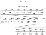
MACヘッダ50は、図10に示すように、複数項目のヘッダ情報51〜57からなり、その先頭部にフレーム制御情報51を含んでいる。上記フレーム制御情報51自体も、図示するように複数項目の情報511〜522からなっている。MACフレームのデータ部が最終フラグメントか否かは、More Fragmentビット516によって判定できる。フレーム符号化部12は、MACヘッダ50を生成する時、最終フラグメント以外のデータブロックに対しては、上記More Fragmentビット516に“0”を設定し、最終フラグメントのデータブロックに対しては“1”を設定する。
上記MACフレーム500の受信側装置では、上記More Fragmentビット516をチェックすることによって、受信フレームのデータ部がIPパケットの最後のフラグメントか否かを判定できる。
【0034】
以上の実施例から明らかなように、本発明によれば、送信データのプロトコル種別、アプリケーション種別に適合した最適なMTU長で、無線区間のパケット伝送を行うことができる。尚、上記実施例では、MTU長の決定に際して、送信元ポート番号、宛先ポート番号、プロトコル番号の順に判定優先度を与えたが、これとは異なった優先順位を採用してもよい。
【0035】
MTU長を指定するMTUテーブル21をNV(Non Volatile)RAM等の不揮発性メモリで構成した場合、送受信機の出荷時に、既知のポート番号またはプロトコル番号と対応する最適MTU値を予め書込んでおき、その後、必要に応じてテーブル内容を更新するようにすればよい。新たなエントリの追加や既存MTU値の変更は、例えば、無線ネットワークに接続された保守用PCからテーブル更新情報を含む制御メッセージをブロードキャストし、各無線送受信機が、上記制御メッセージに応答して、各々のMTUテーブルの内容を書き換えるようにすればよい。
【0036】
MTUテーブル21をRAM等の揮発性メモリで構成した場合は、例えば、データ処理部10が備えるROMまたは不揮発性のメモリ部にマスタ用のMTUテーブル情報を保持しておき、無線送受信機の電源がオンとなった時、上記マスタ用のMTUテーブル情報をMTUテーブル21に自動的に複写するようにすればよい。電源がオンとなった時、各無線送受信機が保守用PCと自動的に交信して、保守用のPCからテーブルエントリをダウンロードするようにしてもよい。
【0037】
図11は、本発明による無線送受信機からの出力信号を受信する無線ネットワーク用の無線中継機の1例を示す。
ここに示した無線中継機は、第1、第2の2つの無線送受信機1A、1Bからなる。無線送受信機1A(1B)は、図1で説明したフレーム符号化部12A(12B)、変調部13A(13B)、RF部14A(14B)、復調部15A(15B)、フレーム判定部16A(16B)からなる。これら2つの無線送受信機1A、1Bは、無線送受信機1Aのフレーム判定部16Aの出力信号が無線送受信機1Bのフレーム符号化部12Bに入力され、無線送受信機1Bのフレーム判定部16Bの出力信号が無線送受信機1Aのフレーム符号化部12Aに入力されるように接続されている。
【0038】
第1無線送受信機1Aは、アンテナ19Aから受信した無線信号を復調し、受信フレームが自局宛のエラーのないフレームであれば、これを第2無線送受信機1Bの送信系に入力する。第2無線送受信機1Bは、フレーム符号化部12Bにおいて、上記受信フレームの宛先アドレスを予め指定された次の無線中継機のアドレスに書き換え、誤り検出ビットを付け替えた後、変調部13Bに入力する。変調部13Bの出力は、RF部14Bで所定電力レベルをもつ無線信号に変換され、アンテナ19Bから送信される。第2無線送受信機1Bのアンテナ19Bから受信された逆方向の無線信号についても、上記と同様の動作で無線中継される。
【0039】
上述した無線中継機を含む通信ネットワークでは、フレーム送信元となった無線送受信機が決定したフラグメント長に従って、受信フレームの中継動作が繰り返される。従って、本発明の無線送受信機のように、送信元で出力フレームのMTU長を最適化しておけば、無線中継区間における伝送遅延の問題を回避することが可能となる。
【0040】
以上、本発明の一実施例についてTCP/IPプロトコルやIEEE802.11プロトコルを適用して説明したが、本発明は実施例に示したプロトコルに限定されるものではなく、他のプロトコルにも適用可能である。
【0041】
【発明の効果】
本発明によれば、以下の効果が期待できる。アプリケーションやプロトコル種別に応じて、無線区間でのMTU長を決定するので、スループットの向上やサービス品質の向上に有効である。無線区間転送単位を柔軟に設定できるので、中継時の伝送遅延時間短縮に有効である。アプリケーション対応、プロトコル種別対応にMTUサイズを登録したテーブルは外部から追加、変更が可能なため、システムの追加・変更に柔軟に対応できる。データのMAC層以下のプロトコルが実行するため既存の上位プロトコルに影響を与えない。
【図面の簡単な説明】
【図1】本発明による無線送受信機の1実施例を示すブロック構成図。
【図2】MTU決定部20が参照するMTUテーブルの1例を示す図。
【図3】本発明の無線送受信機が適用される通信の1例を示す図。
【図4】図3のクライアント10Bとサーバ10Aとの間で交信されるIPパケット400のヘッダ内容1例を示す図。
【図5】IPヘッダ43の詳細フォーマットを示す図。
【図6】TCPヘッダ41の詳細フォーマットを示す図。
【図7】UDPヘッダ42の詳細フォーマットを示す図。
【図8】MTU決定部20が実行するMTU決定処理を示すフローチャート。
【図9】フレーム符号化部12に入力されるIPパケット400と、出力されるMACフレーム500との関係を説明するための図。
【図10】MACフレーム500に付加されるMACヘッダ50の詳細フォーマットを示す図。
【図11】本発明による無線送受信機からの出力信号を受信する無線ネットワーク用の無線中継機の1例を示す図。
【符号の説明】
10:データ処理部、11:送信バッファ、12:フレーム符号化部、13:変調部、14:RF部、15:復調部、16:フレーム判定部、17:データ組立部、20:MTU決定部、21:MTUテーブル。[0001]
BACKGROUND OF THE INVENTION
The present invention relates to a radio transceiver, and more particularly to a radio transceiver that performs data transmission / reception by switching an upper layer protocol to be applied.
[0002]
[Prior art]
In recent years, with the spread of the Internet and low-cost communication networks, the use of IP in networks has progressed. In an IP network, data is delivered from a source to a destination according to the IP protocol.
IP is a protocol in the network layer (third layer) in the OSI reference model, and TCP and UDP are in the transport layer (fourth layer) as higher protocols. TCP and UDP play a role of mediating between IP and application programs. As lower IP protocols, there are data link layer (second layer) and physical layer (first layer) protocols. For example, Ethernet (registered trademark) defined in IEEE802.3 and IEEE802.11. There is a wireless LAN.
[0003]
Wireless LAN technology is also applied to wireless access that implements a subscriber network wirelessly. In an IP network, various applications (for example, WEB access, IP phone, video conference, etc.) spanning wireless and wired systems. Is executable.
There are applications that require real-time performance, such as video distribution and IP phone, and applications that do not require real-time performance, such as file data download. Transport layer protocols such as TCP and UDP are properly used according to the application. In general, UDP is applied to applications such as moving image distribution and IP phone that require real-time performance. TCP has functions such as flow control and error control, and has low real-time performance, but is applied to data transmission applications that are expected to provide reliable and efficient communication.
[0004]
[Problems to be solved by the invention]
In the communication in the wireless section, transmission / reception is controlled by the protocol of the data link layer and the physical layer. In this case, encoding and decoding are performed for each data block serving as a transmission unit. Therefore, if the transmission unit is increased, the transmission delay time is increased. Also, if the transmission unit is increased, the probability of occurrence of a frame error due to line disturbance or the like increases, so the data retransmission processing in the data link layer, the higher network layer, and the application layer increases.
[0005]
These retransmission processes not only lower the throughput but also cause degradation of service quality in applications that require real-time performance, because data that has been delayed due to retransmission becomes a discard target. In addition, since encoding and decoding are performed for each link in the radio section, the transmission delay time increases in proportion to the increase in the number of radio links. In particular, in a communication procedure in which the next data block is transmitted after waiting for an acknowledgment from the destination, the throughput decreases due to an increase in transmission delay time.
[0006]
On the other hand, if the transmission unit of the radio section is reduced, the ratio of overhead parts such as headers and error detection bits added for each data block increases, and the throughput decreases. In TCP, the concept of window size is introduced to reduce the influence of transmission delay time on throughput. The window size means a data size that can be transmitted without waiting for an acknowledgment from the destination. On the transmitting side, data blocks can be transmitted one after another without waiting for a response from the destination within the window size range. . Therefore, by increasing the window size, the influence of the transmission delay time described above on the throughput can be reduced.
[0007]
However, in the conventional wireless transceiver, even if various protocols corresponding to applications are prepared above the data link layer, the protocol below the data link layer is always the same regardless of changes in these upper layer protocols. Because of the control action, the system as a whole could not guarantee optimal performance and quality of service.
[0008]
An object of the present invention is to provide a radio transceiver in which a protocol below the data link layer executes an appropriate control operation corresponding to a protocol operating in an upper layer.
Another object of the present invention is to provide a radio transceiver in which a transmission unit of a data block in a radio section is variable according to an upper layer protocol.
[0009]
[Means for Solving the Problems]
In order to achieve the above object, the present invention provides a wireless transceiver including a transmitter and a receiver, wherein the transmitter includes:
Means for determining a data type of a transmission packet, and determining a value of a maximum transmission unit (MTU) according to the data type;
Means for dividing a transmission packet into a plurality of blocks according to the MTU value and generating a communication frame for a radio section for each divided block;
And means for converting the communication frame for the radio section into a radio signal and transmitting the radio frame.
[0010]
More specifically, the determination means includes, for example, a table for storing an MTU value designated in advance corresponding to the data type, and the MTU value to be used by the communication frame generation means by referring to the table. To decide.
[0011]
According to an embodiment of the present invention, the table stores an MTU value corresponding to the application program type, and the determining means refers to the table according to the type of the application program that handles the transmission packet, and The MTU value to be used by the communication frame generation means is determined. The type of application program can be determined from, for example, the port number included in the header portion of the transmission packet.
[0012]
According to another embodiment of the present invention, the table stores an MTU value corresponding to the communication protocol type, and the determining means refers to the table according to the protocol type applied to the transmission packet, The MTU value to be used by the communication frame generating means is determined. The protocol type can be determined from, for example, a protocol number included in the header part of the transmission packet.
[0013]
According to a preferred embodiment of the present invention, the table includes: a first table storing MTU values corresponding to application program types; and a second table storing MTU values corresponding to communication protocol types. Thus, the determining means refers to the first table according to the type of the application program that handles the transmission packet, and when there is no corresponding data in the first table, the second table is determined according to the protocol type applied to the transmission packet. The MTU value to be used by the communication frame generating means is determined by referring to the above.
[0014]
According to the present invention, since the communication frame for the radio section can be generated with the optimum MTU corresponding to the protocol type and the application type for the transmission data, it is possible to guarantee good performance and service quality as the whole radio communication system. .
[0015]
DETAILED DESCRIPTION OF THE INVENTION
Embodiments in which the present invention is applied to an IEEE802.11 wireless LAN will be described below with reference to the drawings. IEEE802.11 is a standard related to a physical layer in a wireless LAN and a MAC (Media Access Control) layer located below the data link layer.
[0016]
FIG. 1 is a block diagram showing an embodiment of a radio transceiver according to the present invention.
The radio transceiver includes a
[0017]
The transmission data (transmission frame) generated by the
[0018]
In the MTU table 21, for example, as shown in FIG. 2, an MTU table 21A for port numbers and an MTU table 21B for protocol numbers are prepared.
[0019]
In the port number MTU table 21A, a plurality of
[0020]
The
[0021]
The
[0022]
On the other hand, a radio signal from another device received by the antenna is frequency-converted by the
[0023]
FIG. 3 shows a case where the wireless client terminal 10B refers to a Web page on the
For example, the IP address “172.20.100.34” is assigned to the wireless client terminal 10B, and TCP and UDP are used as the
[0024]
On the other hand, in this example, the
[0025]
When referring to the Web page, the Web browser of the client 10B communicates with the HTTP of the
The
[0026]
FIG. 5 shows the detailed format of the
The
[0027]
FIG. 8 shows a flowchart of an
The
[0028]
Next, the port number MTU table 21A is searched according to the transmission source port number 411 (or 421) and the destination port number 412 (or 422) (203). First, the source port number is searched, and if the corresponding entry is found (204), the MTU length is set to the value specified by the entry (208). When the entry corresponding to the transmission source port number is not registered, the MTU table 21A is searched with the destination port number, and the MTU length is set to the designated value of the entry.
[0029]
If there is no entry corresponding to the transmission source port number and the destination port number in the MTU table 21A, the protocol number MTU table 21B is searched according to the protocol number 433 (205). When an entry corresponding to the
[0030]
When the MTU length is determined, the state of the
[0031]
For the state determination (210) of the
[0032]
9 shows the relationship between the
The
[0033]
As shown in FIG. 10, the
The receiving side device of the MAC frame 500 can determine whether or not the data portion of the received frame is the last fragment of the IP packet by checking the
[0034]
As is clear from the above embodiments, according to the present invention, packet transmission in a wireless section can be performed with an optimal MTU length that is suitable for the protocol type and application type of transmission data. In the above embodiment, when the MTU length is determined, the determination priority is given in the order of the transmission source port number, the destination port number, and the protocol number. However, a different priority order may be adopted.
[0035]
When the MTU table 21 for specifying the MTU length is configured by a nonvolatile memory such as NV (Non Volatile) RAM, an optimal MTU value corresponding to a known port number or protocol number is written in advance at the time of shipment of the transceiver. Thereafter, the table contents may be updated as necessary. In order to add a new entry or change an existing MTU value, for example, a control message including table update information is broadcast from a maintenance PC connected to the wireless network, and each wireless transceiver responds to the control message. What is necessary is just to rewrite the contents of each MTU table.
[0036]
When the MTU table 21 is configured by a volatile memory such as a RAM, for example, the master MTU table information is held in the ROM or the non-volatile memory unit included in the
[0037]
FIG. 11 shows an example of a wireless repeater for a wireless network that receives an output signal from a wireless transceiver according to the present invention.
The wireless repeater shown here includes first and
[0038]
The
[0039]
In a communication network including the above-described wireless repeater, the received frame is repeatedly relayed according to the fragment length determined by the wireless transmitter / receiver serving as the frame transmission source. Therefore, if the MTU length of the output frame is optimized at the transmission source as in the wireless transceiver of the present invention, the problem of transmission delay in the wireless relay section can be avoided.
[0040]
As described above, the TCP / IP protocol and the IEEE802.11 protocol are applied to the embodiment of the present invention. However, the present invention is not limited to the protocol shown in the embodiment and can be applied to other protocols. It is.
[0041]
【The invention's effect】
According to the present invention, the following effects can be expected. The MTU length in the radio section is determined according to the application and protocol type, which is effective for improving throughput and improving service quality. Since the wireless section transfer unit can be set flexibly, it is effective for shortening the transmission delay time at the time of relay. A table in which MTU sizes are registered for application and protocol types can be added and changed from the outside, so that it is possible to flexibly deal with additions and changes of systems. Since the protocol below the MAC layer of data is executed, the existing higher level protocol is not affected.
[Brief description of the drawings]
FIG. 1 is a block diagram showing an embodiment of a wireless transceiver according to the present invention.
FIG. 2 is a diagram illustrating an example of an MTU table referred to by an
FIG. 3 is a diagram showing an example of communication to which the wireless transceiver of the present invention is applied.
4 is a view showing an example of header contents of an
5 is a diagram showing a detailed format of an
6 is a diagram showing a detailed format of a
7 is a diagram showing a detailed format of a UDP header 42. FIG.
FIG. 8 is a flowchart showing MTU determination processing executed by the
9 is a diagram for explaining a relationship between an
10 is a view showing a detailed format of a
FIG. 11 is a diagram showing an example of a wireless repeater for a wireless network that receives an output signal from a wireless transceiver according to the present invention.
[Explanation of symbols]
10: data processing unit, 11: transmission buffer, 12: frame encoding unit, 13: modulation unit, 14: RF unit, 15: demodulation unit, 16: frame determination unit, 17: data assembly unit, 20: MTU determination unit , 21: MTU table.
Claims (6)
送信パケットのデータ種別を判別し、データ種別に応じて最大転送単位(MTU:Maximum Transmission Unit)の値を決定するための手段と、
上記MTU値に従って送信パケットを複数のブロックに分割し、分割ブロック毎に無線区間用の通信フレームを生成するための手段と、
上記無線区間用の通信フレームを無線信号に変換して送信するための手段とを有することを特徴とする無線送受信機。In a wireless transceiver including a transmitter and a receiver, the transmitter is
Means for determining a data type of a transmission packet, and determining a value of a maximum transmission unit (MTU) according to the data type;
Means for dividing a transmission packet into a plurality of blocks according to the MTU value, and generating a communication frame for a radio section for each divided block;
And a means for converting the communication frame for the radio section into a radio signal and transmitting the radio frame.
前記決定手段が、前記送信パケットを扱うアプリケーションプログラムの種別に従って第1テーブルを参照し、該第1テーブルに該当データがなかった場合に、上記送信パケットに適用されたプロトコル種別に従って第2テーブルを参照することによって、前記通信フレーム生成手段で使用すべきMTU値を決定することを特徴とする請求項2に記載の無線送受信機。The table includes a first table storing MTU values corresponding to application program types, and a second table storing MTU values corresponding to communication protocol types,
The determining means refers to the first table according to the type of the application program that handles the transmission packet, and refers to the second table according to the protocol type applied to the transmission packet when there is no corresponding data in the first table. The wireless transceiver according to claim 2, wherein an MTU value to be used by the communication frame generation unit is determined.
Priority Applications (1)
| Application Number | Priority Date | Filing Date | Title |
|---|---|---|---|
| JP2002227018A JP3793489B2 (en) | 2002-08-05 | 2002-08-05 | Wireless transceiver |
Applications Claiming Priority (1)
| Application Number | Priority Date | Filing Date | Title |
|---|---|---|---|
| JP2002227018A JP3793489B2 (en) | 2002-08-05 | 2002-08-05 | Wireless transceiver |
Publications (3)
| Publication Number | Publication Date |
|---|---|
| JP2004072294A JP2004072294A (en) | 2004-03-04 |
| JP2004072294A5 JP2004072294A5 (en) | 2004-12-16 |
| JP3793489B2 true JP3793489B2 (en) | 2006-07-05 |
Family
ID=32014166
Family Applications (1)
| Application Number | Title | Priority Date | Filing Date |
|---|---|---|---|
| JP2002227018A Expired - Fee Related JP3793489B2 (en) | 2002-08-05 | 2002-08-05 | Wireless transceiver |
Country Status (1)
| Country | Link |
|---|---|
| JP (1) | JP3793489B2 (en) |
Families Citing this family (6)
| Publication number | Priority date | Publication date | Assignee | Title |
|---|---|---|---|---|
| EP1742500B1 (en) * | 2004-04-30 | 2018-04-11 | Mitsubishi Denki Kabushiki Kaisha | Mobile station, base station, communication system, data amount information transmitting method, transmission control information notifying method, and radio communication method |
| US20060245384A1 (en) * | 2005-05-02 | 2006-11-02 | Talukdar Anup K | Method and apparatus for transmitting data |
| JP2007288491A (en) * | 2006-04-17 | 2007-11-01 | Nippon Telegr & Teleph Corp <Ntt> | Dividing circuit of frame, and transmission system and method using dividing circuit |
| CN101197783A (en) * | 2007-12-28 | 2008-06-11 | 华为技术有限公司 | Method for data message transmission and converter |
| JP2009303036A (en) * | 2008-06-16 | 2009-12-24 | Toshiba Corp | Packet transceiver |
| KR101567868B1 (en) | 2009-08-31 | 2015-11-20 | 한국전자통신연구원 | / apparatus for transmitting/receiving data in usn and its method |
Family Cites Families (6)
| Publication number | Priority date | Publication date | Assignee | Title |
|---|---|---|---|---|
| JPH01226252A (en) * | 1988-03-04 | 1989-09-08 | Pfu Ltd | System for dividing transmission data for plural hierarchy protocols |
| JPH05153131A (en) * | 1991-12-02 | 1993-06-18 | Mitsubishi Electric Corp | Lan terminal equipment |
| JPH07336375A (en) * | 1994-06-14 | 1995-12-22 | Hitachi Ltd | Data transfer system |
| JPH10233809A (en) * | 1997-02-20 | 1998-09-02 | Matsushita Electric Ind Co Ltd | Concentrator and converter |
| JP3349926B2 (en) * | 1997-07-10 | 2002-11-25 | 三菱電機株式会社 | Receiving control device, communication control system, and communication control method |
| JP2000124950A (en) * | 1998-10-12 | 2000-04-28 | Nec Corp | Method and device for setting transmission/reception parameter |
-
2002
- 2002-08-05 JP JP2002227018A patent/JP3793489B2/en not_active Expired - Fee Related
Also Published As
| Publication number | Publication date |
|---|---|
| JP2004072294A (en) | 2004-03-04 |
Similar Documents
| Publication | Publication Date | Title |
|---|---|---|
| US7274730B2 (en) | QoS control method for transmission data for radio transmitter and radio receiver using the method | |
| CN113411313B (en) | Data transmission method, device and system | |
| US7742454B2 (en) | Network performance by dynamically setting a reassembly timer based on network interface | |
| KR100785293B1 (en) | System and Method for TCP Congestion Control Using Multiple TCP ACKs | |
| US9236936B2 (en) | System and method for low-complexity, high-speed preprocessing of encapsulated packets in a broadband communications network | |
| US20110044338A1 (en) | Throughput in a lan by managing tcp acks | |
| EP3518504B1 (en) | Methods and systems for transmission of data over computer networks | |
| US20010017862A1 (en) | IP router device having a TCP termination function and a medium thereof | |
| US20070076618A1 (en) | IP communication device and IP communication system therefor | |
| US6327626B1 (en) | Method and apparatus for MSS spoofing | |
| KR20020037361A (en) | Manipulating header fields for improved performance in packet communications | |
| EP1798913B1 (en) | Transport control method in wireless communication system | |
| JP3645895B2 (en) | Wireless transceiver, QoS control device, and transmission data QoS control method | |
| Sun et al. | The Internet underwater: An IP-compatible protocol stack for commercial undersea modems | |
| CN107707476A (en) | Efficient wireless relay device and method based on FPGA | |
| CN111131179B (en) | Service processing method, device, network equipment and storage medium | |
| JP3793489B2 (en) | Wireless transceiver | |
| US8364832B2 (en) | Data segregation and fragmentation in a wireless network for improving video performance | |
| Papadopoulos et al. | RFC 4944: per-hop fragmentation and reassembly issues | |
| KR101116265B1 (en) | Wireless device with dynamic fragmentation threshold adjustment | |
| Rattal et al. | An effective practical method for narrowband wireless mesh networks performance | |
| WO2020199030A1 (en) | Compression processing method, decompression processing method and related devices | |
| Marchese | Performance analysis of the TCP behavior in a GEO satellite environment | |
| KR100624686B1 (en) | System and Method for setting packet Maximum Transmission Unit of IPv6 transition tunnel using Packet too big message | |
| JP2013013093A (en) | Improving throughput in lan by managing tcp acks |
Legal Events
| Date | Code | Title | Description |
|---|---|---|---|
| A521 | Written amendment |
Free format text: JAPANESE INTERMEDIATE CODE: A523 Effective date: 20040115 |
|
| A621 | Written request for application examination |
Free format text: JAPANESE INTERMEDIATE CODE: A621 Effective date: 20040115 |
|
| A977 | Report on retrieval |
Free format text: JAPANESE INTERMEDIATE CODE: A971007 Effective date: 20050414 |
|
| A131 | Notification of reasons for refusal |
Free format text: JAPANESE INTERMEDIATE CODE: A131 Effective date: 20050426 |
|
| RD02 | Notification of acceptance of power of attorney |
Free format text: JAPANESE INTERMEDIATE CODE: A7422 Effective date: 20050622 |
|
| TRDD | Decision of grant or rejection written | ||
| A01 | Written decision to grant a patent or to grant a registration (utility model) |
Free format text: JAPANESE INTERMEDIATE CODE: A01 Effective date: 20060322 |
|
| A61 | First payment of annual fees (during grant procedure) |
Free format text: JAPANESE INTERMEDIATE CODE: A61 Effective date: 20060407 |
|
| R150 | Certificate of patent or registration of utility model |
Free format text: JAPANESE INTERMEDIATE CODE: R150 |
|
| FPAY | Renewal fee payment (event date is renewal date of database) |
Free format text: PAYMENT UNTIL: 20100414 Year of fee payment: 4 |
|
| FPAY | Renewal fee payment (event date is renewal date of database) |
Free format text: PAYMENT UNTIL: 20110414 Year of fee payment: 5 |
|
| FPAY | Renewal fee payment (event date is renewal date of database) |
Free format text: PAYMENT UNTIL: 20120414 Year of fee payment: 6 |
|
| FPAY | Renewal fee payment (event date is renewal date of database) |
Free format text: PAYMENT UNTIL: 20130414 Year of fee payment: 7 |
|
| FPAY | Renewal fee payment (event date is renewal date of database) |
Free format text: PAYMENT UNTIL: 20140414 Year of fee payment: 8 |
|
| LAPS | Cancellation because of no payment of annual fees |