JP3791292B2 - Ring groove forming method and ring groove forming apparatus for spherical polishing apparatus - Google Patents
Ring groove forming method and ring groove forming apparatus for spherical polishing apparatus Download PDFInfo
- Publication number
- JP3791292B2 JP3791292B2 JP2000080393A JP2000080393A JP3791292B2 JP 3791292 B2 JP3791292 B2 JP 3791292B2 JP 2000080393 A JP2000080393 A JP 2000080393A JP 2000080393 A JP2000080393 A JP 2000080393A JP 3791292 B2 JP3791292 B2 JP 3791292B2
- Authority
- JP
- Japan
- Prior art keywords
- annular groove
- support
- groove
- sphere
- cutting tool
- Prior art date
- Legal status (The legal status is an assumption and is not a legal conclusion. Google has not performed a legal analysis and makes no representation as to the accuracy of the status listed.)
- Expired - Fee Related
Links
Images


Description
【0001】
【発明の属する技術分野】
本発明は球体研磨装置の環状溝成形方法及び環状溝成形装置に関し、より詳しくは、転がり軸受の転動体等に使用される球体を研磨加工する球体研磨装置において、研磨加工の際に前記球体を案内するための環状溝成形方法及び環状溝成形装置に関する。
【0002】
【従来の技術】
従来より、転がり軸受の転動体等に使用される球体の研磨加工は、図12に示すような球体研磨装置を使用して行われることが知られている。
【0003】
すなわち、該球体研磨装置は、同心円状に複数の環状溝101が対向状に成形された2個の研磨盤(回転盤102及び固定盤103)と、球体104が収容されたコンベア105とを備え、コンベア105を矢印b方向に回転させながら、矢印a方向に回転駆動する回転盤102と固定盤103との間に球体104を搬送・供給し、球体104を両盤の環状溝101間に所定の加圧力で挟持しながら転走させることにより、球体104に研磨加工を施している。
【0004】
ところで、この種の球体研磨装置で高精度な球体加工を行うためには上述した環状溝101の溝深さが深いのが好ましく、所望の高精度な研磨加工を施すためには被加工物である球体104の球径の20%〜40%の溝深さが必要とされている。
【0005】
そして、従来より、上記環状溝は、予め別途旋盤等により溝加工を施して成形するか、或いは特開平10−44008公報に開示されているように、平板形状の固定盤を研磨装置本体に装着すると共に、回転盤支持体に切削工具を装着し、該切削工具を使用して該固定盤に切削加工を施し、これにより、まず、固定盤に環状溝を成形し、その後、所謂「盤ならし加工」を施すことにより回転盤に環状溝を成形している。すなわち、回転盤側の環状溝は、固定盤に環状溝を成形した後、所定の加圧力でもって固定盤と回転盤との間に球体を挟持し、遊離砥粒を援用しながら回転盤を回転させて球体を転走させることにより成形している。
【0006】
【発明が解決しようとする課題】
しかしながら、上述したように別途溝加工を施して研磨盤(回転盤102及び固定盤103)に環状溝を成形した場合、該研磨盤を研磨装置本体に装着しても溝加工時の加工誤差や取付誤差等により、図13に示すように、回転盤102の環状溝101の中心線cと球体104の軸回転の中心線c′とが一致しなかったり、或いは双方の環状溝101同士の位置が完全な対向位置とはならず、位置誤差Δtが生じる。したがって、このような状態で球体研磨を行うと環状溝101の形状が摩滅により変形したり、或いは球体104と環状溝101との間の接触状態不良や回転盤102の回転精度が低下し、高精度な研磨加工を施すことが困難であるという問題点があった。
【0007】
また、上記特開平10−44008公報に開示された環状溝の成形方法では、固定盤を研磨装置本体に装着して固定盤に所望溝深さの環状溝を形成し、その後、盤ならし加工を行うことにより平板形状の回転盤にも徐々に環状溝を形成しており、したがって固定盤及び回転盤を共に装置本体に装着した状態で環状溝を成形しているため、上述のような加工誤差や取付誤差による不具合は生じないが、回転盤側の環状溝を成形するためには球体を長時間に亙って、固定盤と回転盤との間に挟持させて転走させなければならず、したがって所望の環状溝を得るためには非常な長時間を要するという問題点があった。
【0008】
本発明はこのような問題点に鑑みてなされたものであり、高精度な研磨加工を施すことのできる研磨加工用環状溝を短時間で得ることのできる球体研磨装置の環状溝成形方法及び環状溝成形装置を提供することを目的とする。
【0009】
【課題を解決するための手段】
上記目的を達成するために本発明に係る球体研磨装置の環状溝成形方法は、固定盤支持体と回転盤支持体とを研磨装置本体内の所定位置に配し、第1の切削工具を前記回転盤支持体に装着すると共に、平板形状の固定盤を前記第1の切削工具と対向状に前記固定盤支持体に装着し、前記回転盤支持体を回転させながら前記第1の切削工具を軸心方向及び径方向に移動させることにより前記固定盤に同心円状の複数の第1の環状溝を成形し、次いで、平板形状の回転盤を前記固定盤と対向状に前記回転盤支持体に装着し、前記第1の環状溝が成形された前記固定盤と前記平板形状の回転盤との間に球体を挟持・転走させることにより、前記第1の環状溝の軌跡を前記回転盤に転写して該回転盤に転写溝を成形し、次に、第2の切削工具を前記第1の環状溝が成形された前記固定盤に装着し、前記転写溝に基いて前記回転盤に同心円状の複数の第2の環状溝を成形することを特徴としている。
また、上記目的を達成するために、請求項2記載の環状溝成形装置は、球体研磨装置本体に設けられ、固定盤が非回転状態で装着された固定盤支持体と、前記球体研磨装置本体に回転可能に設けられた回転盤支持体とを備える環状溝成形装置において、前記回転盤支持体に前記固定盤と対向状に装着され、前記回転盤支持体とともに回転しながら前記回転盤支持体の軸心方向及び径方向に移動することにより、前記固定盤に同心円状の複数の第1の環状溝を成形する第1の切削工具と、前記固定盤に径方向に移動可能に装着され、前記回転盤支持体の回転により、前記第1の切削工具に代えて前記回転盤支持体に装着される回転盤に、前記複数の第1の環状溝の軌跡に基いて同心円状の複数の第2の環状溝を成形する第2の切削工具とを有することを特徴とする。
【0010】
上記環状溝成形方法によれば、回転盤支持体に装着された第1の切削工具を使用して固定盤に第1の環状溝を成形し、次いで、該第1の環状溝の軌跡を回転盤に転写して該回転盤に転写溝を成形し、その後転写溝に基づいて第2の環状溝を回転盤に成形しているので、第1の環状溝の軌跡が転写された転写溝に基づいて第2の環状溝が成形されることにより、第1及び第2の環状溝は完全に対向する位置に成形され、加工誤差や取付誤差が生じることもない。しかも、第2の切削工具により転写溝に基づいて前記第2の環状溝を成形しているので、転写溝の成形を溝深さが比較的浅い段階で終了し、引き続いて第2の切削工具により第2の環状溝を成形することにより、長時間の「盤ならし加工」が不要となり、短時間で所望の深さの環状溝を成形することができる。
【0011】
また、上記環状溝成形方法及び環状溝成形装置において、第2の切削工具の切削部の先端形状は被加工物である球体の球形に対応した形状とするのが好ましい。すなわち、前記切削部を斯かる形状とすることにより、より短時間で容易に所望形状の第2の環状溝を成形することができる。
【0012】
さらに、切削部が矩形状又はV字状とされた第3の切削工具を使用し、第1の環状溝又は第2の環状溝を成形した後、これら環状溝の少なくとも一方の環状溝の底部に凹所を成形するのも好ましい。すなわち、第1の環状溝又は第2の環状溝の少なくとも一方の環状溝の底部に凹所を成形することにより、環状溝に供給される球体と環状溝とのマッチングが不良となったときでも凹所が所謂「逃げ」の作用を呈することとなり、球体の研磨精度が低下するのを防止することができる。
【0013】
また、第1及び第2の切削工具のうちの少なくとも一方の切削工具を被加工物(球体)の形状に対応した形状対応部を有すると共に、その先端を矩形状又はV字状とすることにより、前記第3の切削工具を別途使用することなく凹所を有する第1の環状溝又は第2の環状溝を得ることができる。
【0014】
さらに、上記第1又は第2の環状溝のいずれか一方の環状溝において、環状溝間に形成される平面部が段差を有するように前記第1の切削工具又は第2の切削工具を使用して前記平面部に切削加工を施すのも好ましい。すなわち、平面部間に段差を設けることにより、球体には摩擦力の差に起因してスピンが生じ、これにより球体の自転軸が傾斜し、短時間で球体の全表面が万遍なく研磨され、加工精度と作業効率の向上を図ることができる。
【0015】
【発明の実施の形態】
以下、本発明の実施の形態を図面に基づいて詳説する。
【0016】
図1は本発明に係る球体研磨装置の環状溝成形方法の一実施の形態を示す工程図であって、該環状溝成形方法は、固定盤1に第1の環状溝2を成形する第1の環状溝成形工程(I)と、第1の環状溝2の溝軌跡を回転盤3に転写して転写溝4を成形する転写溝成形工程(II)と、前記転写溝4に基づき回転盤3に第2の環状溝5を成形する第2の環状溝成形工程(III)と、「盤ならし加工」を行う仕上げ工程(IV)とからなり、これら第1及び第2の環状溝2、5は、研磨装置本体上で行われる。
【0017】
すなわち、第1の環状溝成形工程では、図1(I)に示すように、研磨装置本体内に配設された回転盤支持体7に第1の切削工具6を装着すると共に、平板形状の固定盤1を固定盤支持体8に装着して該固定盤支持体8を前記第1の切削工具6と対向状に配する。次いで、回転盤支持体7を回転させながら軸方向に所定量移動させることにより固定盤1を第1の切削工具6で切削し、第1の環状溝2を成形する。そしてその後、第1の切削工具6を所定量だけ径方向に移動させて上述の処理を繰り返し、複数の第1の環状溝2を固定盤1上に同心円状に成形する。
【0018】
次に、転写溝成形工程では、図1(II)に示すように、平板形状の回転盤3を固定盤1と対向するように回転盤支持体7に装着し、第1の環状溝2が成形された固定盤1と前記回転盤3との間に被加工物と同一形状の球体10を挟持・転走させ、矢印Aに示すように、前記第1の環状溝2の軌跡を回転盤3に転写させて該回転盤3に転写溝4を成形する。
【0019】
次に、第2の環状溝成形工程では、図1(III)に示すように、先端部が前記球体の球形状に対応した形状とされた第2の切削工具11を第1の環状溝2が成形された固定盤1に装着し、前記転写溝4に基いて切削加工を行い、同心円状の複数の第2の環状溝5を回転盤3に成形し、その後第2の切削工具11を転写溝4の溝ピッチに対応する所定量だけ径方向に移動させて上述の処理を繰り返し、複数の第2の環状溝5を回転盤3上に同心円状に成形する。
【0020】
そして最後に、仕上げ工程では、図1(IV)に示すように、被加工物と同一形状の球体10を使用して「盤ならし加工」を行い、これにより環状溝同士が完全に互いの対向する位置に成形された研磨盤(固定盤1及び回転盤3)が製造される。
【0021】
このように本実施の形態では、球体研磨装置の研磨装置本体内に固定盤支持体8及び回転盤支持体7を配した状態で固定盤1及び回転盤3に夫々第1及び第2の環状溝2、5を成形しており、以下、上記環状溝成形方法を具体的に説明する。
【0022】
まず、前記第1及び第2の環状溝2、5を成形するための球体研磨装置について説明する。
【0023】
図2は上記球体研磨装置の縦断面図である。
【0024】
同図において、12は基台であって、該基台12上には固定盤支持体8及び回転盤支持体7が設けられている。
【0025】
そして、固定盤支持体8には固定盤1が装着されると共に、回転盤支持体7には回転盤3が前記固定盤1と対向状に装着されている。
【0026】
また、回転盤支持体7は、第1の回転軸13と一体的に形成されると共に、スプライン機構14を介して第2の回転軸15に連設され、かつ第2の回転軸15の基端にはプーリ16が固着されている。そして、プーリ16はベルト(不図示)を介してモータ(不図示)に接続され、該モータを駆動することにより該モータからの動力が第2の回転軸15及び第1の回転軸13に伝達され、回転盤支持体7を介して回転盤3が回転する。
【0027】
また、第1の回転軸13は、転がり軸受17a、17bを介して略円筒形状の案内体18に回転可能に支持されると共に、第2の回転軸15は、転がり軸受19a,19bを介して基台12の側面に配設された略円筒形状の支持部材20に回転可能に支持されている。
【0028】
また、支持部材20の円周方向には複数個のシリンダ21が配設されると共に、該シリンダ21からはピストンロッド22が伸縮可能に突設され、かつ該ピストンロッド22の先端は案内体18の平面部に固着されている。さらに、シリンダ21内の油圧室は不図示の油圧回路に接続され、油圧を介してピストンロッド22を伸縮させることにより、案内体18、第1の回転軸13及び回転盤支持体7が一体となって矢印B方向(軸方向)に往復運動する。すなわち、案内体18は、不図示の案内スライド機構により矢印B方向に往復運動可能に構成されており、ピストンロッド22を伸縮させることにより回転盤3は矢印B方向に往復運動する。
【0029】
このように構成された球体研磨装置においては、球体10を固定盤1と回転盤3との間に挟持し、油圧を介してピストンロッド22の伸縮量を制御することにより加圧力を調整し、これにより多数の球体10に研磨加工を施すことができる。
【0030】
次に、上記球体研磨装置の環状溝成形方法について、各工程を順次説明する。(I)第1の環状溝成形工程
図3は第1の環状溝成形用に組み替えた球体研磨装置の要部縦断面図である。
【0031】
同図において、固定盤支持体8にはメタルボンドのダイヤモンド砥石からなる固定盤1が装着されると共に、回転盤支持体7には、回転盤3に代えて、第1の切削工具6が装着される。すなわち、回転盤支持体7には、断面L字状の工具取付台23が不図示のボルト等を介して前記固定盤1と対向状に固着され、さらに、前記工具取付台23にはダイアモンドバイトからなる切削部24を有する第1の切削工具6が矢印C方向に往復運動可能に取り付けられている。
【0032】
具体的には、工具取付台23には係合溝23aが形成されており、第1の切削工具6の基端に設けられた係合溝6aが前記係合溝23aに係合されている。また、第1の切削工具6の略中央部には雌ネジ部が内設されており、該雌ネジ部は工具取付台23の底部23bによって支持されるネジ棒25に螺着されている。そして、ネジ棒25の基端には摘み部26が設けられており、該摘み部26を回動させることにより第1の切削工具6を矢印C方向に往復運動可能としている。
【0033】
また、回転盤支持体7の中央部には孔27が貫設されると共に、第1の回転軸13からは杆状の受け部材28が突設されている。また、固定盤支持体8には孔29が形成されており、所定軸長を有する杆状のストッパ30が軸受部31を介して固定盤支持体8に回転可能且つ矢印D方向に往復運動可能に支持されている。そして、受け部材28の先端面とストッパ30の先端面とは互いに対向し、ストッパ30の先端面を受け部材28の先端面に当接させることにより、第1の環状溝2の溝深さを制御できるように構成されている。
【0034】
具体的には、ストッパ30の基端部は、静圧軸受32を介してネジ軸33の先端部に接続されている。該ネジ軸33は、例えばボールネジからなり、ボールネジのナット34を介して固体盤支持体8に回転自在に支持されている。また、ネジ軸33の基端部には平歯車35が固定され、さらに該平歯車35はピニオン歯車36に噛合されている。尚、該ピニオン歯車36は、固定盤支持体8に付設されたブラケット37により回転自在に支持され、サーボモータ38により回転駆動する。すなわち、サーボモータ38を正逆回転させることにより、ピニオン歯車36、平歯車35、ネジ軸33及び静圧軸受32を介して、ストッパ30を矢印D方向に位置調節できるようになっている。
【0035】
このようにして固定盤1に成形される第1の環状溝2の溝深さは、サーボモータ38により位置調整されたストッパ30が第1の回転軸13に突設された受け部材28に当接することにより決定されることとなる。
【0036】
尚、静圧軸受32は、ストッパ30とネジ軸33とを、夫々単独回転可能となるようにカップリング部材39を有しており、また該カップリング部材39には作動油流出孔39aが穿設され、静圧軸受32には、不図示のポンプにより作動液が供給できるようになっている。
【0037】
すなわち、ネジ軸33の中央部には作動液供給路40が貫設され、その一端部はカップリング部材39内に開放されると共に、その他端部は回転継手41、ホース42を介してダイヤフラム型制御絞り部43の流出口43aに接続されている。該ダイヤフラム型制御絞り部43の流入口43bは、前記ポンプの吐出口に接続され、該ポンプの吸入口は不図示の作動液タンクに接続されている。尚、ダイヤフラム型制御絞り部43は、基台12の端面に固着されている。
【0038】
そして、作動液タンク内の作動油がポンプによりダイヤフラム型制御絞り部43の流入口43bに供給されると、該ダイヤフラム型制御絞り部43により、ストッパ30とネジ軸33との対向面間の隙間δが一定に保たれるように作動液の圧力が自動的に絞られ、その作動液は流出口43aからホース42、回転継手41及び作動液供給路40を順次介して静圧軸受32のカップリング部材39内に供給される。カップリング部材39内に供給された作動液は、カップリング部材39の作動液流出孔39aから図示しない作動液回収回路を介して前記作動液タンク内に回収される。
【0039】
このように組み替えられた球体研磨装置においては、以下のようにして第1の環状溝2が成形される。
【0040】
すなわち、まず摘み部26を操作してネジ棒25を正逆回転させることにより、第1の切削工具6を矢印C方向に移動させ切削部24を初期位置に設定する。尚、切削部24の設定位置は、固定盤1を固定盤支持体8に装着する前に印(マーク)を付しておいてもよく、また、固定盤1を固定盤支持体8に装着した後にスケール等で測定して設定してもよい。
【0041】
次に、切削部24の初期位置、受け部材28の先端位置、及び第1の環状溝2の設定溝深さに基づいてサーボモータ38を駆動させ、ストッパ30の位置を調整する。
【0042】
ここで、第1の環状溝2の溝深さは、ハードディスクドライブ(以下、「HDD」という)用軸受のような高精度な研磨加工を得るためには、球体10の球径の20〜40%に設定するのが好ましい。
【0043】
次いで、回転盤支持体7を回転させながら該回転盤支持体7を固定盤方向に移動させる。これにより、第1の切削工具6は回転盤支持体7と一体となって回転しながら固定盤1に近接し、固定盤1は前記第1の切削工具6の切削部24により切削加工が施され、ストッパ30と受け部材28とが当接することにより、1本の第1の環状溝2の成形が終了する。
【0044】
このようにして1本の第1の環状溝2が成形されると、次いで、不図示のダイヤルゲージ等で測定しながら第1の切削工具6を所定量だけ矢印C方向に移動させて切削部24の位置を調整し設定した後、上述と同様の切削加工を繰り返し、第1の環状溝2を同心円状に成形する。
【0045】
以下、上述の処理を所定回数繰り返すことにより、所定本数の複数の第1の環状溝2を同心円状に成形する。
【0046】
このように本実施の形態によれば、回転盤支持体7の第1及び第2の回転軸13、15と同軸を使って切削加工を施しているため、回転盤支持体7の回転中心との偏心を生じることなく第1の環状溝2を成形することができる。
【0047】
尚、本実施の形態においては、回転盤支持体7には、第1の切削工具6等、該回転盤支持体7の装着物に対するバランスウエイトを取り付けることが望ましい。
【0048】
(II)転写溝成形工程
転写溝成形工程では、まず、図3に示す球体研磨装置から、第1の切削工具6等の回転盤支持体7への装着物やストッパ30等の固定盤支持体8に組み込まれた部材を除去し、メタルボンドのダイヤモンド砥石からなる平板形状の回転盤3を回転盤支持体7に装着する(図2参照)。そして、この状態で回転盤3と固定盤1との間に被加工物と同一形状の球体10を供給し、該球体10を回転盤3と固定盤1との間に挟持させながら第1の回転軸13と連動するモータ(不図示)を駆動させて回転盤3を回転させる。そして、遊離砥粒を援用しながら球体10を第1の環状溝2内で転走させ、これにより第1の環状溝2の溝軌跡を回転盤3側に転写し該回転盤3に転写溝4を成形する。
【0049】
ここで、溝深さとしては、転写溝成形工程を早期に終了して全工程時間の短縮化を図るためには球体10の球径の2%〜10%程度となるようにするのが好ましい。その理由は、転写溝4の溝深さが球径の2%以下の場合は溝軌跡が不明瞭となって明確に認識できないため、後述の第2の環状溝5の加工精度が低下し、一方、転写溝4の溝深さが球径の10%以上となるまで球体10を挟持・転走させると転写溝4の成形に長時間を要するからである。
【0050】
すなわち、高精度な研磨加工を行うためには、回転盤3にも第1の環状溝2と同様、球体10の球径の20%〜40%程度の溝深さを有する第2の環状溝5を成形する必要があるが、この転写溝成形工程では、球体10の球径の2〜10%程度の浅い溝を、遊離砥粒の援用下、短時間で成形し、次工程に移る。
【0051】
(III)第2の環状溝成形工程
続く第2の環状溝成形工程では、まず、球体研磨装置を第2の環状溝成形用に組み替える。
【0052】
図4は第2の環状溝成形用に組み替えた球体研磨装置の要部正面図であり、図5は図4のX−X矢視図である。
【0053】
図4及び図5において、固定盤1には、球体10を供給・排出するための切欠部44が設けられており、該切欠部44にスライド機構45が取り付けられている。
【0054】
スライド機構45は、具体的には支持部材46がボルト47を介してベース48に立設され、さらに支持部材46には第1の把持部49aを有する位置調整部材49が挿通されると共に、該位置調整部材49にはスライド部材50が係合されている。そして、スライド部材50の基端には第2の把持部51が螺合されると共に、先端には第2の切削工具11が固着されている。そして、該第2の切削工具11の先端には被加工物である球体10の半径と同一径のR寸法を有するダイヤモンドバイトからなる切削部52が設けられている。また、スライド部材50には位置測定器53が連設されると共に、該位置測定器53は杆状支持部材54に係合されている。
【0055】
そして、該スライド機構45においては、第1の把持部49aを操作することによりスライド部材50は矢印D方向に移動し、第2の把持部51を操作することによりスライド部材50は矢印E方向に移動する。
【0056】
また、スライド機構45の上方には拡大鏡55が配設されている。すなわち、該拡大鏡55は、方向を自在に変更することのできる支持部材56を介して固定盤支持体8に取り付けられている。
【0057】
ここで、拡大鏡55の倍率としては10〜100倍のものを使用するのが好ましい。その理由は、拡大鏡55の倍率が10倍以下であると第2の切削工具11の位置を正確に所望位置に設定するのが困難となり、一方、拡大鏡55の倍率が100倍を超えると視野が狭くなり且つ焦点を合わせるのが困難になるからである。
【0058】
また、回転盤3及び回転盤支持体7の中央部に貫設されている孔には第3の回転軸57が挿通されており、該第3の回転軸57の基端は第1の回転軸13と一体となって回転可能となるように該第1の回転軸13に連接されると共に、その先端には半円形状の突起部58が形成されている。また固定盤支持体8には超硬合金製の雄ネジ部を有するストッパ59がナット60を介して螺着されている。
【0059】
このようにスライド機構45、拡大鏡55及び第3の回転軸57が組み込まれた球体研磨装置においては、第1の把持部49aを操作し位置測定器53で矢印D方向のスライド部材50の位置調整を行い、さらに、拡大鏡55を使用し、図6(a)に示すように、転写溝4のR形状の底部と切削部52のR形状の先端とが対応するように第2の把持部51を操作し、第2の切削工具11の初期位置を決定する。また、第2の環状溝5の溝深さが所定量に到達すると第3の回転軸57の突起部58がストッパ59に当接するようにナット60を回転させてストッパ59の位置を調整する。
【0060】
このようにしてスライド部材50の初期位置及びストッパ59の位置の設定が終了した後、回転盤3を回転させながら案内スライド機構により突起部58がストッパ60に当接するまで回転盤3を固定盤1方向に移動させ、図6(b)に示すように第2の環状溝5を成形する。
【0061】
次に、固定盤1に成形されている第1の環状溝2と同一の溝ピッチ分だけ、上述と同様、第1及び第2の把持部49a、50を操作してスライド部材50を移動させ、切削部52による同様の切削加工を行う。
【0062】
以下、上述の処理を所定回数繰り返すことにより、同心円状の複数の第2の環状溝5を成形する。
【0063】
このように本実施の形態によれば、第1の環状溝2を転写した転写溝4に基づいて回転盤3に第2の環状溝5を成形するので、固定盤1の第1の環状溝2と完全に対向して位置ずれの生じない第2の環状溝5を回転盤3に成形することができ、また、転写溝4の成形を溝深さが比較的浅い段階で終了し、引き続いて第2の切削工具11により第2の環状溝を成形することにより、短時間で所望の深さの環状溝を成形することができ、もって高精度な研磨加工を施すことのできる第1の環状溝2及び第2の環状溝5を短時間で得ることができる。
【0064】
尚、切削部52の先端が摩耗して所謂「R崩れ」を起こさないためには十分に低い切削速度(例えば、5m/min)で行うのが好ましく、またミスト状切削油を使用するのが好ましい。
【0065】
(IV)仕上げ工程
次に、球体研磨装置を図2の状態に戻し、被加工物と同一形状の球体10を使用して「盤ならし加工」を行い、切削痕を除去し、第1及び第2の環状溝2、5の成形を終了する。
【0066】
そしてこの後、回転盤1及び固定盤3を研磨装置本体から取り外すことなく、被加工物である球体10の研磨加工が行なうことにより、所望の高精度な真円度を有する球体10を得ることができる。
【0067】
このように本実施の形態では、研磨装置本体上で固定盤1及び回転盤3の双方に夫々第1及び第2の環状溝2、5を成形しているので、回転盤3と固定盤1との環状溝の中心、及び球体10の回転中心とが完全に一致し、しかも所望深さの環状溝を成形することができるので、例えばHDD等のコンピュータ関連機器に使用される玉軸受用転動体のように極めて高精度な加工精度の要求される球体に対しても好適した球体研磨装置を得ることができる。
【0068】
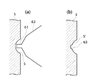
図7は本発明の第2の実施の形態の要部を模式的に示した図であって、本第2の実施の形態では、上記第1の実施の形態に示すような第2の環状溝5を成形した後、第2の切削工具11に代えて、図7(a)に示すように、先端部61が矩形状に形成された第3の切削工具62を使用し、図7(b)に示すように、第2の環状溝5の底部に前記切削部61の形状に対応した凹状のステッキ溝63を成形している。
【0069】
すなわち、第1及び第2の環状溝2、5間に供給される球体と環状溝とのマッチングが不良等となった場合は、図8に示すように環状溝5の底部5aのみで球体10が研磨加工されるため、真円度の低い三角形状の等径ひずみ球に研磨加工される場合がある。このため、従来では、環状溝の低部が矩形状のステッキ溝やV溝を有する研磨盤と交換していた。
【0070】
そこで、本第2の実施の形態では、第2の環状溝5を成形した後、第2の切削工具11を第3の切削工具62に取り替え、該第3の切削工具62で回転盤3に切削加工を施すことにより第2の環状溝5の底部に凹所としてのステッキ溝63を形成し、これによりステッキ溝63が「逃げ」(ポケット)としての作用をなすこととなり、球体10の全表面が確実に研磨され、所望の研磨加工を行うことができる。
【0071】
尚、上記第2の実施の形態では第2の環状溝5にステッキ溝を成形しているが、上記ステッキ溝を第2の環状溝5側に成形するのに代えて、第1の環状溝2側に成形してもよく、或いは第1の環状溝2及び第2の環状溝5の双方に成形してもよい。また、凹所の形状としてはステッキ溝に代えてV溝としてもよい。すなわち、第3の切削工具62の切削部61をV字状とし、V溝を成形するようにするのも好ましい。
【0072】
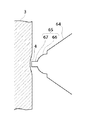
図9は第3の実施の形態の要部を模式的に示した図であって、本第3の実施の形態では、第1の実施の形態に示した第2の切削工具11に代えて、図に示すような第2の切削工具64を使用して第2の環状溝5を成形している。
【0073】
すなわち、上記第2の切削工具64は、切削部65が被加工物である球体10の球径と同一のR寸法とされたR部66を有すると共に先端には矩形部67が突設されている。
【0074】
そして、これにより第2の実施の形態に示した第2の環状溝5′(図7(b)参照)の成形工程を2回に分けることなく一度に行うことができる。
【0075】
また、図示は省略するが、第1の環状溝2の底部に凹所を成形する場合も、第1の切削工具6を改良することにより同様に成し得るのはいうまでもない。
【0076】
図10は本発明の第4の実施の形態を模式的に示した図であって、本第4の実施の形態では、環状溝間の平面部68に段差Lが形成されるように第2の切削工具11を使用して平面部68を切削加工している。すなわち、図11に示すように、球体10の自転軸Yが軸芯方向に対して常に90°を成している場合は、球の極の環状溝2、5の溝部69a〜69dに当たらずに1周するため、研磨されない部分が生じて所望の研磨精度を得るには長時間を要し、また研磨速度を上げると真円度の低下を招来する虞が生じる。
【0077】
そこで、本第4の実施の形態では、平面部間で段差Lを形成することにより、摩擦力の差に起因したスピンを球体10に生じさせ、これにより球体10の自転軸YがY′の位置に傾斜可能として自転軸の向きの変化を誘発し、因って短時間で球体の全表面が万遍なく研磨され、加工精度と作業効率の向上を図ることができる。
【0078】
また、上記第4の実施の形態では、第2の環状溝5間の平面部68を切削しているが、第1の環状溝2間の平面部68を切削するようにしてもよい。
【0079】
尚、本発明は上記実施の形態に限定されるものではない。上記実施の形態では図2に示す球体研磨装置を使用して第1及び第2の環状溝2、5を成形しているが、本発明の要旨を逸脱しない範囲内で、研磨装置本体上で第1及び第2の環状溝2、5を成形することができる球体研磨装置であればよく、図2に示すような構造の球体研磨装置に限定されるものではない。
【0080】
【発明の効果】
以上詳述したように、本発明に係る球体研磨装置の環状溝成形方法によれば、固定盤支持体と回転盤支持体とを研磨装置本体内の所定位置に配し、第1の切削工具を回転盤支持体に装着すると共に、平板形状の固定盤を第1の切削工具と対向状に固定盤支持体に装着し、回転盤支持体を回転させながら第1の切削工具を軸心方向及び径方向に移動させることにより固定盤に同心円状の複数の第1の環状溝を成形し、次いで、平板形状の回転盤を固定盤と対向状に回転盤支持体に装着し、第1の環状溝が成形された固定盤と平板形状の回転盤との間に球体を挟持・転走させることにより、第1の環状溝の軌跡を回転盤に転写して該回転盤に転写溝を成形し、次に、第2の切削工具を第1の環状溝が成形された固定盤に装着し、転写溝に基いて回転盤に同心円状の複数の第2の環状溝を成形するので、研磨装置本体上で第1及び第2の環状溝が成形されることとなり、したがって回転盤と固定盤との環状溝の中心、及び被加工物である球体の回転中心とが完全に一致し、しかも第2の切削工具を使用することにより所望の溝深さを有する第2の環状溝を短時間で成形することができ、もって高精度な研磨加工を施すことのできる研磨加工用環状溝を短時間で得ることができる。したがって、例えばHDD等のコンピュータ関連機器に使用される玉軸受用転動体のように極めて高精度な加工精度の要求される球体に対しても好適した球体研磨装置を得ることができる。
【図面の簡単な説明】
【図1】本発明に係る球体研磨装置の環状溝成形方法の一実施の形態を示す工程図である。
【図2】球体研磨装置の一例を示す縦断面図である。
【図3】固定盤に環状溝(第1の環状溝)を成形する場合の球体研磨装置の要部断面図である。
【図4】回転盤に環状溝(第2の環状溝)を成形する場合の球体研磨装置の概略正面図である。
【図5】図4のX−X矢視図である。
【図6】第2の環状溝の成形方法を説明する図である。
【図7】本発明の第2の実施の形態を模式的に示した図である。
【図8】環状溝に供給される球体と環状溝とのマッチングが不良となった場合の問題点を説明するための図である。
【図9】本発明の第3の実施の形態を模式的に示した図である。
【図10】本発明の第4の実施の形態を模式的に示した図である。
【図11】球体の自転軸と研磨状態の関係を説明するための図である。
【図12】球体研磨装置による研磨方法を説明するための斜視図である。
【図13】従来の球体研磨装置で球体を研磨する場合の問題点の一例を示す図である。
【符号の説明】
1 固定盤
2 第1の環状溝
3 回転盤
4 転写溝
5 第2の環状溝
6 第1の切削工具
7 回転盤支持体
8 固定盤支持体
10 球体
11 第2の切削工具[0001]
BACKGROUND OF THE INVENTION
The present invention relates to a method for forming an annular groove of a spherical polishing apparatus and Annular groove More specifically, in a sphere polishing apparatus for polishing a sphere used for a rolling element of a rolling bearing or the like, an annular for guiding the sphere during the polishing process. Mizonari The present invention relates to a forming method and an annular groove forming apparatus.
[0002]
[Prior art]
Conventionally, it has been known that polishing of a sphere used for a rolling element of a rolling bearing is performed using a sphere polishing apparatus as shown in FIG.
[0003]
That is, the sphere polishing apparatus includes two polishing disks (a rotating
[0004]
By the way, in order to perform highly accurate sphere processing with this type of sphere polishing apparatus, it is preferable that the groove depth of the above-described
[0005]
Conventionally, the annular groove is formed in advance by groove processing with a lathe or the like, or a flat plate-shaped fixed plate is mounted on the polishing apparatus main body as disclosed in JP-A-10-44008. At the same time, a cutting tool is attached to the rotating disk support, and the cutting tool is used to cut the fixed plate, whereby an annular groove is first formed in the fixed plate. An annular groove is formed in the rotating disk by applying a “grinding”. That is, the annular groove on the turntable side is formed by forming a ring groove on the fixed platen, sandwiching a sphere between the fixed platen and the turntable with a predetermined pressure, and using the free abrasive grains. It is formed by rolling and rolling the sphere.
[0006]
[Problems to be solved by the invention]
However, when an annular groove is formed in the polishing machine (the rotating
[0007]
Further, in the annular groove forming method disclosed in the above-mentioned JP-A-10-44008, an annular groove having a desired groove depth is formed on the stationary platen by mounting the stationary platen on the polishing apparatus body, and then the plate leveling process. As a result, the annular groove is gradually formed in the plate-shaped rotating disk. Therefore, the annular groove is formed with both the stationary disk and the rotating disk mounted on the apparatus main body. There is no problem due to errors or mounting errors, but in order to form an annular groove on the turntable side, the sphere must be rolled over a long period of time and sandwiched between the fixed platen and the turntable. Therefore, there is a problem that it takes a very long time to obtain a desired annular groove.
[0008]
The present invention has been made in view of such problems, and an annular groove forming method for a spherical polishing apparatus capable of obtaining an annular groove for polishing capable of performing high-precision polishing in a short time, and Annular groove An object is to provide a molding apparatus.
[0009]
[Means for Solving the Problems]
In order to achieve the above object, an annular groove forming method for a sphere polishing apparatus according to the present invention includes a fixed plate support and a rotating plate support arranged at predetermined positions in a polishing device main body, and the first cutting tool is arranged in the above-described manner. Attaching to the rotating plate support, a flat plate-like fixed plate is attached to the fixed plate support so as to face the first cutting tool, and the rotating plate support is rotated while rotating the rotating plate support. First cutting tool Axial direction And radial direction To form a plurality of concentric first annular grooves on the stationary platen, and then mount a flat plate-like rotating plate on the rotating plate support so as to face the stationary platen. A trajectory of the first annular groove is transferred to the rotating disk by sandwiching and rolling a sphere between the fixed disk in which the annular groove is formed and the flat disk-shaped rotating disk. Next, a second cutting tool is mounted on the stationary platen on which the first annular groove is formed, and a plurality of second concentric circles are formed on the rotating plate based on the transfer groove. An annular groove is formed.
Moreover, in order to achieve the said objective,
[0010]
How to form the annular groove To the law According to the present invention, the first annular groove is formed in the stationary platen using the first cutting tool mounted on the rotating plate support, and then the locus of the first annular groove is transferred to the rotating plate. On the turntable Since the transfer groove is formed, and then the second annular groove is formed on the turntable based on the transfer groove, By forming the second annular groove based on the transfer groove to which the locus of the first annular groove is transferred, The first and second annular grooves are formed at positions that completely face each other, and processing errors and mounting errors do not occur. Moreover, since the second annular groove is formed on the basis of the transfer groove by the second cutting tool, the formation of the transfer groove is finished at a stage where the groove depth is relatively shallow, and then the second cutting tool. By forming the second annular groove by the above, long-time “board leveling” becomes unnecessary, and a desired time can be achieved in a short time. In depth An annular groove can be formed.
[0011]
The annular groove forming method and Annular groove In the molding apparatus, it is preferable that the tip shape of the cutting portion of the second cutting tool is a shape corresponding to the spherical shape of the sphere that is the workpiece. That is, by making the cutting part into such a shape, the second annular groove having a desired shape can be easily formed in a shorter time.
[0012]
Furthermore, after forming the first annular groove or the second annular groove using a third cutting tool whose cutting part is rectangular or V-shaped, the bottom of at least one of the annular grooves It is also preferable to form a recess in the surface. That is, by forming a recess in the bottom of at least one annular groove of the first annular groove or the second annular groove, even when matching between the sphere supplied to the annular groove and the annular groove becomes poor The concave portion exhibits a so-called “escape” action, and it is possible to prevent the spherical grinding accuracy from being lowered.
[0013]
Further, at least one of the first and second cutting tools has a shape-corresponding portion corresponding to the shape of the workpiece (sphere), and the tip thereof is made rectangular or V-shaped. The first annular groove or the second annular groove having a recess can be obtained without using the third cutting tool separately.
[0014]
Further, in either one of the first and second annular grooves, the first cutting tool or the second cutting tool is used so that a flat portion formed between the annular grooves has a step. It is also preferable to cut the planar portion. In other words, by providing a step between the flat portions, spin occurs in the sphere due to the difference in frictional force, which causes the rotation axis of the sphere to tilt, and the entire surface of the sphere is uniformly polished in a short time. Therefore, it is possible to improve processing accuracy and work efficiency.
[0015]
DETAILED DESCRIPTION OF THE INVENTION
Hereinafter, embodiments of the present invention will be described in detail with reference to the drawings.
[0016]
FIG. 1 is a process diagram showing an embodiment of an annular groove forming method for a spherical polishing apparatus according to the present invention. The annular groove forming method is a first method for forming a first
[0017]
That is, in the first annular groove forming step, as shown in FIG. 1 (I), the
[0018]
Next, in the transfer groove forming step, as shown in FIG. 1 (II), a flat plate-shaped
[0019]
Next, in the second annular groove forming step, as shown in FIG. 1 (III), the
[0020]
And finally, in the finishing step, as shown in FIG. 1 (IV), the “slab leveling” is performed using the
[0021]
As described above, in the present embodiment, the fixed
[0022]
First, a spherical polishing apparatus for forming the first and second
[0023]
FIG. 2 is a longitudinal sectional view of the sphere polishing apparatus.
[0024]
In the figure,
[0025]
The fixed
[0026]
The
[0027]
The first
[0028]
A plurality of
[0029]
In the sphere polishing apparatus configured as described above, the
[0030]
Next, each step will be sequentially described with respect to the annular groove forming method of the sphere polishing apparatus. (I) First annular groove forming step
FIG. 3 is a longitudinal sectional view of an essential part of a spherical polishing apparatus that has been recombined for forming the first annular groove.
[0031]
In the figure, a
[0032]
Specifically, an
[0033]
In addition, a
[0034]
Specifically, the proximal end portion of the
[0035]
The groove depth of the first
[0036]
The
[0037]
That is, a hydraulic
[0038]
When the hydraulic oil in the hydraulic fluid tank is supplied to the
[0039]
In the spherical polishing apparatus thus rearranged, the first
[0040]
That is, first, by operating the
[0041]
Next, the
[0042]
Here, the groove depth of the first
[0043]
Next, the
[0044]
When one first
[0045]
Thereafter, by repeating the above-described process a predetermined number of times, a predetermined number of the first
[0046]
Thus, according to the present embodiment, the
[0047]
In this embodiment, the
[0048]
(II) Transfer groove forming process
In the transfer groove forming step, first, a rotating disk support such as the
[0049]
Here, the groove depth is preferably about 2% to 10% of the diameter of the
[0050]
That is, in order to perform high-precision polishing, the second annular groove having a groove depth of about 20% to 40% of the spherical diameter of the
[0051]
(III) Second annular groove forming step
In the subsequent second annular groove forming step, first, the sphere polishing apparatus is rearranged for forming the second annular groove.
[0052]
FIG. 4 is a front view of a main part of the spherical polishing apparatus recombined for forming the second annular groove, and FIG. 5 is a view taken along the line XX of FIG.
[0053]
4 and 5, the fixed
[0054]
Specifically, in the
[0055]
In the
[0056]
Further, a magnifying
[0057]
Here, the magnification of the
[0058]
A third
[0059]
In the spherical polishing apparatus in which the
[0060]
After the setting of the initial position of the
[0061]
Next, the first and second
[0062]
Thereafter, by repeating the above-described process a predetermined number of times, a plurality of concentric second
[0063]
As described above, according to the present embodiment, the second
[0064]
In order to prevent the tip of the cutting
[0065]
(IV) Finishing process
Next, the sphere polishing apparatus is returned to the state shown in FIG. 2, and “smoothing” is performed using the
[0066]
Thereafter, the
[0067]
As described above, in the present embodiment, the first and second
[0068]
FIG. 7 is a diagram schematically showing the main part of the second embodiment of the present invention. In the second embodiment, the second annular shape as shown in the first embodiment is shown. After forming the
[0069]
That is, when the matching between the sphere supplied between the first and second
[0070]
Therefore, in the second embodiment, after the second
[0071]
In the second embodiment, the stick groove is formed in the second
[0072]
FIG. 9 is a diagram schematically showing the main part of the third embodiment. In the third embodiment, instead of the
[0073]
That is, the
[0074]
Thus, the molding process of the second
[0075]
Although not shown, it goes without saying that a recess can be formed in the bottom of the first
[0076]
FIG. 10 is a diagram schematically showing a fourth embodiment of the present invention. In the fourth embodiment, the second step is formed so that a step L is formed in the
[0077]
Therefore, in the fourth embodiment, by forming a step L between the plane portions, spin caused by the difference in frictional force is generated in the
[0078]
Moreover, in the said 4th Embodiment, although the
[0079]
The present invention is not limited to the above embodiment. In the above embodiment, the first and second
[0080]
【The invention's effect】
As detailed above, the annular groove forming method of the spherical polishing apparatus according to the present invention To the law According to this, the fixed platen support and the rotary platen support are arranged at predetermined positions in the polishing apparatus main body, the first cutting tool is mounted on the rotary platen support, and the flat plate-shaped fixed platen is first cut. Attaching to the fixed platen support so as to face the tool, while rotating the turntable support First cutting tool Axial direction And radial direction To form a plurality of concentric first annular grooves on the stationary platen, and then mount the flat plate-like rotating plate on the rotating plate support so as to face the stationary platen. By holding and rolling the sphere between the formed fixed plate and the flat plate-shaped rotating plate, the trajectory of the first annular groove is transferred to the rotating plate, and the transfer groove is formed on the rotating plate. In addition, the second cutting tool is mounted on the fixed plate with the first annular groove formed, and a plurality of concentric second annular grooves are formed on the rotating plate based on the transfer groove. Thus, the first and second annular grooves are formed, so that the center of the annular groove between the rotating disk and the stationary disk and the rotation center of the sphere that is the workpiece are completely coincident with each other. No. Having the desired groove depth by using 2 cutting tools Second ring Groove In a short time Can be molded, Therefore, an annular groove for polishing that can be polished with high accuracy can be obtained in a short time. Therefore, it is possible to obtain a sphere polishing apparatus suitable for a sphere that requires extremely high processing accuracy, such as a ball bearing rolling element used in a computer-related device such as an HDD.
[Brief description of the drawings]
FIG. 1 is a process diagram showing one embodiment of a method for forming an annular groove of a spherical polishing apparatus according to the present invention.
FIG. 2 is a longitudinal sectional view showing an example of a sphere polishing apparatus.
FIG. 3 is a cross-sectional view of a main part of a spherical body polishing apparatus when an annular groove (first annular groove) is formed on a stationary platen.
FIG. 4 is a schematic front view of a spherical body polishing apparatus in the case where an annular groove (second annular groove) is formed on a rotating disk.
FIG. 5 is a view taken in the direction of arrows XX in FIG. 4;
FIG. 6 is a diagram illustrating a method for forming a second annular groove.
FIG. 7 is a diagram schematically showing a second embodiment of the present invention.
FIG. 8 is a diagram for explaining a problem when matching between a sphere supplied to the annular groove and the annular groove becomes poor.
FIG. 9 is a diagram schematically showing a third embodiment of the present invention.
FIG. 10 is a diagram schematically showing a fourth embodiment of the present invention.
FIG. 11 is a diagram for explaining a relationship between a rotation axis of a sphere and a polishing state.
FIG. 12 is a perspective view for explaining a polishing method using a spherical polishing apparatus.
FIG. 13 is a diagram showing an example of a problem when a sphere is polished by a conventional sphere polishing apparatus.
[Explanation of symbols]
1 fixed platen
2 First annular groove
3 Turntable
4 Transfer groove
5 Second annular groove
6 First cutting tool
7 Turntable support
8 Fixed platen support
10 Sphere
11 Second cutting tool
Claims (2)
前記回転盤支持体に前記固定盤と対向状に装着され、前記回転盤支持体とともに回転しながら前記回転盤支持体の軸心方向及び径方向に移動することにより、前記固定盤に同心円状の複数の第1の環状溝を成形する第1の切削工具と、
前記固定盤に径方向に移動可能に装着され、前記回転盤支持体の回転により、前記第1の切削工具に代えて前記回転盤支持体に装着される回転盤に、前記複数の第1の環状溝の軌跡に基いて同心円状の複数の第2の環状溝を成形する第2の切削工具とを有することを特徴とする環状溝形成装置。 Provided spherical polishing apparatus main body, a fixed plate support that is mounted in the stationary platen is nonrotatably, in an annular groove forming apparatus and a turntable support provided rotatably in the spherical body polishing apparatus main body,
Wherein the instrumentation wear before Symbol fixed platen and a counter-shaped to the turntable support, by moving in the axial direction and the radial direction of the rotating disk support while rotating together with the rotating disk support, before Symbol fixed platen A first cutting tool for forming a plurality of concentric first annular grooves;
A plurality of the first discs are mounted on the rotating disc mounted on the rotating disc support instead of the first cutting tool by the rotation of the rotating disc support . An annular groove forming apparatus comprising: a second cutting tool that forms a plurality of concentric second annular grooves based on a locus of the annular groove.
Priority Applications (1)
| Application Number | Priority Date | Filing Date | Title |
|---|---|---|---|
| JP2000080393A JP3791292B2 (en) | 2000-03-22 | 2000-03-22 | Ring groove forming method and ring groove forming apparatus for spherical polishing apparatus |
Applications Claiming Priority (1)
| Application Number | Priority Date | Filing Date | Title |
|---|---|---|---|
| JP2000080393A JP3791292B2 (en) | 2000-03-22 | 2000-03-22 | Ring groove forming method and ring groove forming apparatus for spherical polishing apparatus |
Publications (3)
| Publication Number | Publication Date |
|---|---|
| JP2001259981A JP2001259981A (en) | 2001-09-25 |
| JP2001259981A5 JP2001259981A5 (en) | 2004-11-25 |
| JP3791292B2 true JP3791292B2 (en) | 2006-06-28 |
Family
ID=18597500
Family Applications (1)
| Application Number | Title | Priority Date | Filing Date |
|---|---|---|---|
| JP2000080393A Expired - Fee Related JP3791292B2 (en) | 2000-03-22 | 2000-03-22 | Ring groove forming method and ring groove forming apparatus for spherical polishing apparatus |
Country Status (1)
| Country | Link |
|---|---|
| JP (1) | JP3791292B2 (en) |
Families Citing this family (3)
| Publication number | Priority date | Publication date | Assignee | Title |
|---|---|---|---|---|
| JP4785822B2 (en) * | 2007-11-28 | 2011-10-05 | 株式会社天辻鋼球製作所 | Grooving method of vitrified grinding wheel for sphere processing |
| DE102009009254A1 (en) * | 2008-12-19 | 2010-07-01 | Schaeffler Technologies Gmbh & Co. Kg | Method for producing the rolling elements of a ball roller bearing |
| JP6384241B2 (en) * | 2013-10-17 | 2018-09-05 | 株式会社ジェイテクト | Sphere polishing apparatus and sphere polishing method |
-
2000
- 2000-03-22 JP JP2000080393A patent/JP3791292B2/en not_active Expired - Fee Related
Also Published As
| Publication number | Publication date |
|---|---|
| JP2001259981A (en) | 2001-09-25 |
Similar Documents
| Publication | Publication Date | Title |
|---|---|---|
| KR101584265B1 (en) | Lens spherical surface grinding method using dish-shaped grindstone | |
| US4928435A (en) | Apparatus for working curved surfaces on a workpiece | |
| US4760672A (en) | Simultaneously grinding and polishing preforms for optical lenses | |
| WO1999024206A1 (en) | Method and apparatus for polishing inner surface of cylindrical portion of elongated cylindrical work and elongated cylindrical work | |
| JP2712782B2 (en) | Polishing spindle | |
| JP3791292B2 (en) | Ring groove forming method and ring groove forming apparatus for spherical polishing apparatus | |
| JPH1133886A (en) | Method and device for polishing inside surface of glass disc | |
| JP2002361543A (en) | Internal surface grinding device | |
| JPH1044008A (en) | Method and device for polishing sphere, and grooving method for circular channel | |
| JP4285008B2 (en) | Surface processing equipment | |
| JP6303568B2 (en) | Tapered roller grinding apparatus and tapered roller grinding method | |
| JPH06502807A (en) | Manufacturing equipment for valves for power steering devices | |
| JP3835255B2 (en) | Gear tooth surface processing method and apparatus | |
| JP4055796B2 (en) | Sphere polishing equipment | |
| JPH11347896A (en) | Centerless grinding machine | |
| JP5300939B2 (en) | Machining method using finishing tools | |
| JP5308209B2 (en) | Taper hole grinding | |
| JP2003145348A (en) | Gear tooth surface regular position machining method and device | |
| JPH11179641A (en) | Lens centering clamp device and lens centering machine using same | |
| JP2003205459A (en) | Polishing machining device and method | |
| JP6497214B2 (en) | Sphere polishing apparatus and truing method thereof | |
| JP3407691B2 (en) | Grinding method of cylindrical shape of hard brittle material with belt drive rotation applying method | |
| RU2570135C1 (en) | Method of dressing of grinding wheel of centreless grinder | |
| JP3893384B2 (en) | Cylindrical workpiece end grinding machine | |
| JP5973787B2 (en) | Optical element processing tool, grindstone holding tool, optical element processing tool manufacturing method and method of use, and optical member manufacturing method |
Legal Events
| Date | Code | Title | Description |
|---|---|---|---|
| A521 | Written amendment |
Free format text: JAPANESE INTERMEDIATE CODE: A523 Effective date: 20031210 |
|
| A621 | Written request for application examination |
Free format text: JAPANESE INTERMEDIATE CODE: A621 Effective date: 20031210 |
|
| A977 | Report on retrieval |
Free format text: JAPANESE INTERMEDIATE CODE: A971007 Effective date: 20051209 |
|
| A131 | Notification of reasons for refusal |
Free format text: JAPANESE INTERMEDIATE CODE: A131 Effective date: 20051220 |
|
| A521 | Written amendment |
Free format text: JAPANESE INTERMEDIATE CODE: A523 Effective date: 20060217 |
|
| RD03 | Notification of appointment of power of attorney |
Free format text: JAPANESE INTERMEDIATE CODE: A7423 Effective date: 20060217 |
|
| TRDD | Decision of grant or rejection written | ||
| A01 | Written decision to grant a patent or to grant a registration (utility model) |
Free format text: JAPANESE INTERMEDIATE CODE: A01 Effective date: 20060314 |
|
| A61 | First payment of annual fees (during grant procedure) |
Free format text: JAPANESE INTERMEDIATE CODE: A61 Effective date: 20060327 |
|
| R150 | Certificate of patent or registration of utility model |
Free format text: JAPANESE INTERMEDIATE CODE: R150 |
|
| LAPS | Cancellation because of no payment of annual fees |