JP3788366B2 - Speaker device with human body detection function - Google Patents

Speaker device with human body detection function Download PDF

Info

Publication number
JP3788366B2
JP3788366B2 JP2002044837A JP2002044837A JP3788366B2 JP 3788366 B2 JP3788366 B2 JP 3788366B2 JP 2002044837 A JP2002044837 A JP 2002044837A JP 2002044837 A JP2002044837 A JP 2002044837A JP 3788366 B2 JP3788366 B2 JP 3788366B2
Authority
JP
Japan
Prior art keywords
notification sound
sound
signal
human body
speaker
Prior art date
Legal status (The legal status is an assumption and is not a legal conclusion. Google has not performed a legal analysis and makes no representation as to the accuracy of the status listed.)
Expired - Fee Related
Application number
JP2002044837A
Other languages
Japanese (ja)
Other versions
JP2003241704A (en
Inventor
剛彰 平松
正一 秋山
晶子 岡村
Current Assignee (The listed assignees may be inaccurate. Google has not performed a legal analysis and makes no representation or warranty as to the accuracy of the list.)
Panasonic Electric Works Co Ltd
Original Assignee
Matsushita Electric Works Ltd
Priority date (The priority date is an assumption and is not a legal conclusion. Google has not performed a legal analysis and makes no representation as to the accuracy of the date listed.)
Filing date
Publication date
Application filed by Matsushita Electric Works Ltd filed Critical Matsushita Electric Works Ltd
Priority to JP2002044837A priority Critical patent/JP3788366B2/en
Publication of JP2003241704A publication Critical patent/JP2003241704A/en
Application granted granted Critical
Publication of JP3788366B2 publication Critical patent/JP3788366B2/en
Anticipated expiration legal-status Critical
Expired - Fee Related legal-status Critical Current

Links

Images

Description

【0001】
【発明の属する技術分野】
本発明は、人体検知機能付スピーカ装置に関するものである。
【0002】
【従来の技術】
従来より、スーパーマーケット、コンビニエンスストア、飲食店などの店舗の出入口近傍に2個の人感センサを人の移動方向に沿って配置し、2個の人感センサが人体を感知したタイミングから人の移動方向(進入方向又は退出方向)を判別し、その移動方向に対応した音を出力させる人体検知機能付スピーカ装置が提供されている。
【0003】
このような人体検知機能付スピーカ装置では、進入時の報知音と退出時の報知音とが1音ずつ登録されているが、出入口に対して機器を左右何れの側に設置するかによって、進入方向又は退出方向となる移動方向が逆転するため、移動方向の正逆を反転させるスイッチを設け、このスイッチを用いて進入時及び退出時の報知音を出力する方向と実際の方向とを一致させている。
【0004】
【発明が解決しようとする課題】
上記構成の人体検知機能付スピーカ装置では、人体の検知時のみ報知音を出力するようになっているため、報知音の種類などの設定を確認したい場合、その都度人体を検知させて報知音を出力させなければ、報知音の設定を確認することができず、確認作業がしにくいという問題があった。
【0005】
本発明は上記問題点に鑑みて為されたものであり、その目的とするところは、報知音などの設定状態を容易に確認できる人体検知機能付スピーカ装置を提供することにある。
【0006】
【課題を解決するための手段】
上記目的を達成するために、請求項1の発明では、検知エリア内で人体を検知するとともに、その人体の移動方向を検知する検知手段、人体の各移動方向に対応した報知音を記憶する記憶手段、前記記憶手段に記憶された報知音を再生する再生手段、外部よりワイヤレス信号で送信される設定確認信号を受信する受信手段、及び前記検知手段が人体を検知するとその移動方向に応じた報知音を再生手段により再生させるとともに、前記受信手段が設定確認信号を受信すると記憶手段に記憶された各移動方向の報知音を再生手段により音声で出力させる制御手段を有するスピーカ本体と、記憶手段に記憶された各移動方向の報知音を再生手段から音声で出力させるための操作を行う第1の操作手段、第1の操作手段の操作に応じて外部へワイヤレス信号にて設定確認信号を送信する送信手段を有するリモコン設定器とを備え、上記記憶手段には、報知音をそれぞれ記憶する記憶ブロックが複数設けられ、各記憶ブロックに報知音を録音させる録音手段と、各記憶ブロックに記憶された報知音の中から各移動方向に対応して再生する報知音を設定する設定手段とをスピーカ本体に設けるとともに、上記リモコン設定器に、上記記憶手段の個別の記憶ブロックを指定して、当該記憶ブロックに記憶された報知音を強制的に再生させるための操作を行う第2の操作手段を設け、送信手段は、第2の操作手段の操作に応じて外部へワイヤレス信号にて報知音再生信号を送信させており、上記制御手段は、受信手段の受信した報知音再生信号に基づいて指定された記憶ブロックの報知音を再生手段により再生させることを特徴とし、リモコン設定器の第1の操作手段を操作すると、送信手段がワイヤレス信号にて設定確認信号を送信し、この設定確認信号を受信したスピーカ本体では、制御手段が、設定確認信号に応じて各移動方向の報知音を再生手段により音声で出力させているので、人体を検知していない状態でも報知音を強制的に再生でき、リモコン設定器を用いて離れた場所から報知音を音声で容易に確認できる。
【0007】
しかも、録音手段を用いて記憶手段の各記憶ブロックに所望の報知音を録音させることができ、且つ設定手段を用いて各記憶ブロックに録音させた報知音の中から所望の報知音を各移動方向に対応して設定できるから、使用状況に応じた報知音を再生することができる。
【0008】
そのうえ、リモコン設定器の第2の操作手段を操作すると、送信手段がワイヤレス信号にて報知音再生信号を送信させ、この報知音再生信号を受信したスピーカ本体では、制御手段が、報知音再生信号に応じて指定された記憶ブロックの報知音を強制的に再生しているので、リモコン設定器を用いて離れた場所から記憶手段の各記憶ブロックにどのような報知音が録音されているかを容易に確認できる。
【0009】
【発明の実施の形態】
本発明の実施の形態を図1乃至図12を参照して説明する。本実施形態の人体検知機能付スピーカ装置は、例えばスーパーマーケット、コンビニエンスストア、飲食店などの店舗の出入口に設置され、人体の出入りを検知して、報知音を出力するものであり、人体の移動方向に応じて報知音を異ならせることで、人体の進入及び退出を報知したり、店舗内の案内や販促用のメッセージを流したり、さらには侵入者に対して警告するといった用途に用いられる。
【0010】
この人体検知機能付スピーカ装置は、スピーカ本体10と、造営面に固定されるとともにスピーカ本体10が着脱自在に取り付けられる取付ベース23と、リモコン設定器50とで構成される。
【0011】
スピーカ本体10は、図1に示すように、マイクロコンピュータからなる制御部11(制御手段)と、例えば店舗の出入口に人体の移動方向に沿って配置され、人体から放射される熱線を検知することによって検知エリア内の人の存否を検出する焦電センサのような2個の人感センサ12a,12b(検知手段)と、本体に内蔵されたマイクMC1と、外部マイク(図示せず)からの信号が入力されるマイク入力部MC2と、AV機器からの信号が入力されるライン入力部AVXと、内蔵のマイクMC1、マイク入力部MC2又はライン入力部AVXを介して入力された音声信号を音声メモリ14(記憶手段)に録音するとともに、音声メモリ14に記録されている音声信号を再生してスピーカSPから出力させる録音手段及び再生手段としての録再回路13と、外部よりワイヤレス信号で送信された信号を受信する受信部15(受信手段)と、人体検知時に接点信号を出力する出力回路16と、各種の操作を行うための操作部17と、主電源部18と、補助電源部19とで構成される。
【0012】
また、リモコン設定器50は、スピーカ本体10の動作設定を行うための操作部52(第1及び第2の操作手段)と、外部へワイヤレス信号を送信する送信部53(送信手段)と、マイクロコンピュータからなり、操作部52の操作入力に応じた信号を送信部53からワイヤレス信号にて送信させる制御部51とを備える。尚、リモコン設定器50から送信されるワイヤレス信号としては、赤外線のような光信号や電波によるものなど、遠隔操作に利用できる信号であればどのような信号でも良い。
【0013】
ここで、スピーカ本体10、取付ベース23及びリモコン設定器50の構造について以下に説明する。
【0014】
リモコン設定器50は図3に示すような外観形状を備える。リモコン設定器50は、片手で持つことができる程度の大きさに形成された扁平な器体60を備え、器体60の上面には送信部53が配置され、前面には各種の設定操作を行うための操作キーK0〜K12、K21〜K24、K31〜K37が配置されており、これらの操作キーK0…により上述の操作部52が構成される。
【0015】
なお、操作キーK0の釦には「終了/0」という文字が表示され、操作キーK1〜K12の釦にはそれぞれ1〜12の数字が表示されている。操作キーK21,K22の組、操作キーK23,K24の組は、それぞれ、後述するパターンP1,P2の報知音を設定する釦であり、操作キーK21,K22の下側には「P1」という文字が、操作キーK23,K24の下側には「P2」という文字が表示されている。また、操作キーK21,K23は後述する方向D1に対応した報知音、操作キーK22,K24は後述する方向D2に対応した報知音を設定する釦であり、その釦にはそれぞれ「D1」「D2」という文字が表示されている。操作キーK31はモード切替用の操作釦であり、その釦には「入/切」という文字が表示され、釦の上側には「センサ」という文字が表示される。操作キーK32は、人体を検知すると即座に報知音を出力させる機能(この機能を連続鳴動機能と言う)をオン/オフするための釦であり、操作キーK32の釦には「入/切」という文字が表示され、釦の上側には「連続検知」という文字が表示されている。操作キーK33は出力する報知音のパターンをP1又はP2に切り替えるための釦であり、その釦には「P1/P2」という文字が表示され、釦の上側には「出力パターン」という文字が表示される。操作キーK34,K35は音量調節用の操作釦であり、音量を大きくするための操作キーK34には「△」が、音量を小さくするための操作キーK35には「▽」が表示されている。また、操作キーK36は確認操作用、K37は登録操作用の釦であり、それぞれの釦には「確認」「登録」という文字が表示されている。
【0016】
一方、スピーカ本体10は図4乃至図6に示すような外観形状を有しており、スピーカ本体10のケース20は天井面や壁面などの造営面に固定される取付ベース23に着脱自在に取り付けられる。
【0017】
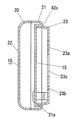
ケース20は、合成樹脂により前面が開口した箱状に形成されたボディ21(図9及び図10参照)と、ボディ21の開口部分の大部分を覆うようにボディ21に被着される合成樹脂製のカバー22とを組立ねじ(図示せず)で結合することにより形成される。ボディ21の開口部分のうちカバー22により覆われていない部分(カバー22の下部中央)は、熱線に対して透過性を有する合成樹脂(例えば高密度ポリエチレン樹脂)で形成された保護カバー24で覆われており、この保護カバー24の裏側に2個の人感センサ12a,12bを保持する人感センサユニット25が収納されている。
【0018】
カバー22の中央部の後面側にはスピーカSPが配設されており、右側下部の後面側にはプリント基板よりなる回路基板30に実装されたマイクMC1が配置されている(図9参照)。また、カバー22にはスピーカSPと対向する部位に多数の音孔22aがマトリクス状に貫設され、さらにマイクMC1と対向する部位にも音孔22bが貫設されている。
【0019】
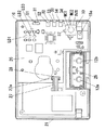
ボディ21の前面側には、上述した制御部11、録再回路13、音声メモリ14、補助電源部19などの回路部品や、通電時に点灯する通電表示用の発光ダイオードLD1や、動作モードに応じて発光色が変化する動作モード表示用の発光ダイオードLD2や、録音レベルを表示するための発光ダイオードLD3や、受信部15を構成するフォトダイオードのような受光素子15aが実装されたプリント基板よりなる回路基板26が配置されており、回路基板26と上述した回路基板30との間はケーブル37を介して電気的接続が為されている。なお、各発光ダイオードLD1〜LD3の発光は、カバー22に設けた透光窓35を通して視認できるようになっている。また、カバー22には受光素子15aと対向する部位に受光窓36が配設されている。受光窓36はワイヤレス信号に対して透光性を有しており、リモコン設定器50から送信された信号を受光素子15aが受光窓36を通して受信できるようになっている。
【0020】
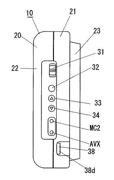
また回路基板26の右側縁には、スライドスイッチからなるモード切替スイッチS1と、タクトスイッチからなるパターン切替スイッチS2、音量アップスイッチS3および音量ダウンスイッチS4と、マイク入力部MC2と、ライン入力部AVXとが配設されている。モード切替スイッチS1の操作摘み31および各スイッチS2〜S4の操作釦32〜34はケース20の右側面に露設されている。またマイク入力部MC2及びライン入力部AVXもケース20の右側面に設けた開口窓から露出しており、外部マイク又はAV機器側のプラグを着脱自在に接続できるようになっている。ここにおいて、モード切替スイッチS1はスピーカ本体10の動作モードを切り替えるためのスイッチであり、操作摘み31を上側の切替位置にスライドさせると人感センサ12a,12bの検知信号に応じて動作し(このモードを通常モードと言う)、中央の切換位置にスライドさせると人感センサ12a,12bの検知信号に関係なく録再回路13が最後に出力した報知音をスピーカSPから出力させ(このモードを再生モードと言う)、下側の切換位置にスライドさせると内蔵のマイクMC1、マイク入力部MC2又はライン入力部AVXを通じて入力された音声信号を録再回路13が音声メモリ14に録音する(このモードを録音モードと言う)。また、パターン切替スイッチS2は移動方向に応じた報知音の組合せを切り替えるためのスイッチであり、音量アップスイッチS3および音量ダウンスイッチS4は音量調節用のスイッチである。
【0021】
一方、取付ベース23は前面が開口した箱状に形成されており、上壁の前端縁にはケース20を取り付けるための2つの取付片23d,23d(図6および図11参照)が上方に延設されており、左右の両側壁の下部内側にはケース20を取り付けるための係合爪23e,23eが突設されている。一方、ボディ21の背面には取付ベース23の前端側が嵌合する凹所21aが凹設され、この凹所21aの内面に上記取付片23d,23dが挿入係止される2つの挿入孔21b,21bが形成されている。また、ボディ21の下部の左右両側には、ボディ21(すなわちケース20)を取付ベース23に着脱自在に取り付けるための2つの取付部材38,38が取着されている。ここにおいて、取付部材38は、一端部に上記係合爪23eの後面に係合可能な係止爪38bを有し他端部がボディ21に固定されて厚み方向に撓み可能な逆J字状の撓み片38aと、撓み片38aの中間部から撓み片38aの厚み方向に延出されボディ21の後壁の前面側で後壁に沿ってスライド自在に移動可能なスライド片38cと、スライド片38cの先端部から下方に延長された操作片38dとを備えている。一方、ボディ21は、後壁に撓み片38aが挿通される貫通孔21cが形成され、両側壁にスライド片38cが挿通される挿通孔21dが形成されている。而して、ケース20を取付ベース23に取り付ける際には、取付ベース23の取付片23d,23dを挿入孔21b,21bに挿入して、ボディ21の両側面から露出した操作片38d,38dを互いに近づく向きに押し込んだ状態で取付ベース23の前部をケース21の後面の凹部21aに嵌め込み、その後で操作片38d,38dから手を離せば係止爪38b,38bが取付ベース23の係合爪23e,23eに係止されることになる。これに対して、取付ベース23からケース20を取り外す際には、操作片38d,38dを互いに近づく向きに押し込んで係止爪38b,38bと係合爪23e,23eとの係合状態を解除してケース20の下部を手前にずらせばよい。
【0022】
また取付ベース23の中央部には、商用電源からの電源電線100を挿通する矩形状の電線挿通孔23cが形成され、電線挿通孔23cの上下両側には2つの取付孔23a,23bが形成されている。上側の取付孔23aの形状はだるま孔状であって、下部の直径が上部の直径よりも大きく形成され、下部は取付ねじの頭部が挿通可能な直径に形成され、上部は取付ねじの頭部が抜けない直径に形成されている。したがって、取付ベース23を造営面に取り付ける際には、造営面に取り付けた取付ねじの頭部を取付孔の下部に通した後に、取付ベース23を下方にスライドさせて取付ねじの頭部を取付孔23aの上部に位置させると、取付ベース23が造営面に仮止めされ、この状態で取付ベース23の中央下部に設けられた取付孔23bを通して取付ねじを造営面に螺合させれば、取付ねじにより取付ベース23が造営面に固定される。
【0023】
ところで、図12は主電源部18及び補助電源部19からなる電源部の回路ブロック図であり、主電源部18では電源スイッチSW及びヒューズFを介して入力された交流電源ACの電源電圧をトランスTrにより降圧し、全波整流器DBで全波整流した後、三端子レギュレータなどの電源ICを用いた5V電源回路18aで安定化している。主電源部18は取付ベース23の前面側に配置され、ケーブル27を介して回路基板26に電気的に接続されており、ケース20が取付ベース23に保持されている状態では、主電源部18からケーブル27を介して回路基板26に動作電源が供給されている。ケーブル27の両端にはコネクタ27aが結線されており、主電源部18及び回路基板26にそれぞれ設けた受け側のコネクタ28,28に対してコネクタ接続されている。なお、主電源部18の電源スイッチSWは押釦スイッチからなり、ケース20を取付ベース23に取り付けている状態では、電源スイッチSWの押釦がケース20によって取付ベース23側に押さえつけられて導通し、主電源部18に通電されるようになっている。
【0024】
補助電源部19は、電池B(バッテリ)を電源として約5Vの一定電圧を生成する5V電源部19aを有しており、ケース20を取付ベース23から取り外して使用する際には、回路基板26と主電源部18との間を接続するケーブル27を外して、ケース20を取付ベース23から取り外した後、ケース20(ボディ21)の後面側に設けた電池ボックス29に電池Bを取り付けて、5V電源部19aにより電池Bを電源として一定電圧を生成させ、制御部11などに動作電源を供給している。尚、ケース20を取付ベース23から取り外すと、電源スイッチSWの押釦を押す力がなくなって、電源スイッチSWがオフになるので、電源の切り忘れを防止できる。
【0025】
次に、この人体検知機能付スピーカ装置の動作について説明する。図2は人感センサユニット25に保持された2個の人感センサ12a,12bの検知エリアを示しており、両人感センサ12a,12bの検知エリアA1,A2は、人体M1,M2の移動方向(図2中の上下方向)において前後に並んで配置される。人体M1が図2中の下側から上側に向かって移動する場合(この方向を方向D1と言う)、人体M1は人感センサ12aの検知エリアA1を通過して人感センサ12bの検知エリアA2内に進入するので、人感センサ12a→人感センサ12bの順番で人体M1を検知する。一方、上述とは逆に人体M2が図2中の上側から下側に向かって移動する場合(この方向を方向D2と言う)は人感センサ12b→人感センサ12aの順番で人体M2を検知する。このように、人体の移動方向D1,D2に応じて2個の人感センサ12a,12bで人体を感知するタイミングが異なるため、スピーカ本体10の制御部11では、両人感センサ12a,12bからの人体検知信号に基づいて人体の移動方向を判別することができ、各移動方向D1,D2にそれぞれ対応付けられた報知音を録再回路13により再生させ、スピーカSPから出力させている。
【0026】
ところで、音声メモリ14には報知音を記憶するための複数の領域(以下、ボックスと言う)が用意され、各ボックスには0〜12までの連続したボックス番号が割り当てられている。表1は各ボックスに記憶された報知音を示しており、0番のボックスには何も音が録音されておらず(無音)、1番から4番までのボックスには「いらっしゃいませ」「ありがとうございました」「ピンポン」「ポロロン」といった4種類の報知音が予め録音されている。なお出荷時には5番から12番までのボックスに報知音が録音されておらず、ユーザ側で所望の報知音を録音させることができる。
【0027】
【表1】

Figure 0003788366
【0028】
ここで、所望の報知音を録音する方法について説明する。一般に、スピーカ本体10は天井や壁面などの高所に設置されて使用されるので、報知音を録音する際には取付ベース23からケース20を取り外し、録音作業のやり易い場所に移動させて録音を行う。なお、ケース20を取付ベース23から取り外して使用する際は、主電源部18と回路基板26との間を接続するケーブル27を外し、ケース20の後面側に設けた電池ボックス29に電池Bを取り付け、電池Bを電源として動作させる。
【0029】
報知音を録音する際には、先ずモード切替スイッチS1の操作摘み31を下側の切換位置にスライドさせて動作モードを録音モードに切り替える。尚、上述のように発光ダイオードLD2は動作モードに応じて発光色が変化し、通常モードでは赤色、再生モードではオレンジ色、録音モードでは緑色で点灯する。
【0030】
ここで、録再回路13に音声信号を入力する方法としては、内蔵のマイクMC1で音声を電気信号に変換して入力する方法、外部マイクからの音声信号をマイク入力部MC2を介して入力する方法、AV機器からの音声信号をライン入力部AVXを介して入力する方法の3通りの方法がある。マイク入力部MC2又はライン入力部AVXにプラグが接続されていなければ、内蔵のマイクMC1からの音声信号が録再回路13に入力される。一方、マイク入力部MC2又はライン入力部AVXにプラグが接続されると、マイクMC1からの入力が自動的に切り離されて、外部マイク又はAV機器からの音声信号がマイク入力部MC2又はライン入力部AVXを通じて録再回路13に自動的に入力され、さらに入力された音声信号がスピーカSPから出力されるようになっている。
【0031】
動作モードが録音モードに切り替えられると、録再回路13に内蔵されたレベルメータ(図示せず)が動作を開始し、入力信号の信号レベルを検出して、発光ダイオードLD3の表示色で信号レベルを表示するようになっている。発光ダイオードLD3は、入力信号の音量が小さい場合は黄色、最適であれば緑色、大きい場合は赤色で点灯するようになっており、入力信号の音量の大小を視覚的に確認することができる。而してユーザが、上述した3通りの方法の何れかで録音したい音(音声メッセージやメロディ音など)を入力して、発光ダイオードLD3の発光色を見ながら、入力信号の音量を調整して録音レベルを最適値に設定した後、リモコン設定器50の操作キーK5〜K12により録音したいボックス番号を入力すると、制御部51が送信部53からボックス番号を示す信号を送信させる。この時、スピーカ本体10の受信部15がリモコン設定器50から送信された信号を受信し、制御部11が受信信号に基づいて発光ダイオードLD2を1秒周期で5秒間緑色で点滅させた後、発光ダイオードLD2を緑色点灯させるとともに、録再回路13の録音動作を開始させる。その後、ユーザがリモコン設定器50の操作キーK0を押操作すると、制御部51は送信部53から録音動作を終了させる信号を送信させ、スピーカ本体10では受信部15がこの信号を受信して、制御部11が録再回路13の録音動作を終了させ、音声メモリ14の指定されたボックスに音声信号を記録させる。
【0032】
ここで、発光ダイオードLD2の点滅中に別のボックス番号に対応した操作キーK5〜K12が押操作された場合は、後に押された操作キーK5〜K12を優先して、キー操作に応じてリモコン送信器50から送信された信号を受信した時点から5秒間、制御部11が発光ダイオードLD2を点滅させた後、後に押された操作キーで指定されたボックスに、入力された音声信号を録音させる。また、発光ダイオードLD2が点灯状態に切り替わった後に何れかの操作キーK5〜K12が押された場合、そのキー入力は無視する。なお、各ボックスに録音可能な音声信号の時間(録音可能時間)は予め決められており、録音動作を開始してからリモコン設定器50の操作キーK0が押されるまでの間にこのボックスに録音可能な時間が経過すると、制御部11は録再回路13の録音動作を終了させるとともに、スピーカSPから警告音を出力させる。
【0033】
ところで、録音するボックスを指定する際に操作キーK0〜K4が押された場合、0番及び1番〜4番までのボックスは固定音用であり、ユーザ側で録音できないため、制御部11は録再回路13を用いてスピーカSPから警告音を出力させる。また、録音モードに切り換えられた状態で数字を表す操作キーK0〜K12以外のキーが押操作された場合にはその入力を無視し、録再回路13を用いてスピーカSPから警告音を出力させる。またリモコン設定器50には、ユーザ側で録音可能な5番から12番までのブロック(記憶ブロック)の録音内容を消去するキーが用意されておらず、先に録音した音声信号を消去したい場合はそのブロックに上書きすることで音声信号を消去すれば良い。
【0034】
上述のように本実施形態の人体検知機能付スピーカ装置は所望の報知音を録音する機能を有し、この録音機能を利用してお店の雰囲気に合わせた音声や音楽、建物内の案内用の音声、警戒監視用の音声などをスピーカ6から出力させることも可能であり、多用途に展開でき、設置場所も建物の出入口だけでなく、建物内に設定することや屋外で設置することも可能である。なお、メーカ側で想定される使用状況に合わせた音声メッセージ(日本語および外国語による挨拶や警告)、効果音(小鳥のさえずりや波の音といった自然の音や鈴、鐘の音など)、メロディ音、警報音及び呼出音を録音したコンパクトディスクを用意し、このコンパクトディスクを出荷時に添付しておけば、このコンパクトディスクに録音された音をコンパクトディスクプレイヤーで再生し、ライン入力部AVXを通じて録再回路13に入力させることで、コンパクトディスクに録音された音の中から所望の音を報知音として録音させることができ、汎用性が高くなる。
【0035】
また、このスピーカ本体10は天井や壁面などの造営面に設置されて使用されるため、頻繁に行う設定操作を本体側で行うのは困難であるから、リモコン設定器50を用いて各種の設定操作を行うようにしている。
【0036】
ここで、リモコン設定器50を用いて、音声メモリ14の12個のボックスに登録された報知音の中から人体検知時に再生させる報知音の組合せを選択する方法について説明する。本実施形態では、人体が方向D1に移動する時の報知音と方向D2に移動する時の報知音とを1つの組(パターン)として複数パターン(本実施形態では例えば2パターン)選択できるようになっており、2つのパターンをそれぞれパターンP1、パターンP2と呼ぶ。
【0037】
例えばパターンP1の方向D1における報知音として7番のボックスに録音された報知音を選択する場合、ケース20を取付ベース23に取り付けている状態でリモコン設定器50の操作キーK31を押すと、送信部53から動作モードを通常モードに切り替える信号が送信され、この信号を受けてスピーカ本体10の制御部11が動作モードを通常モードに切り替えるとともに、発光ダイオードLD2を赤色で点灯させる。その後、リモコン設定器50の操作キーK21を押すと、送信部53からパターンP1の方向D1を指定する信号が送信され、この信号を受けてスピーカ本体10の制御部11は内部タイマ(図示せず)のカウント動作を開始させる。そして、内部タイマによるカウント時間(例えば5秒)のカウント動作が終了するまでの間に、選択するボックス番号(7番)に対応した操作キー(K7)が押されると、送信部53から7番のボックス番号を指定する信号が送信され、この信号を受けてスピーカ本体10の制御部11は内部タイマのカウント動作をリセットして再度開始させる。その後、内部タイマによるカウント時間(例えば5秒)のカウント動作が終了するまでの間に、リモコン設定器50の操作キーK37が押されると、送信部53から報知音を登録する信号が送信され、この信号を受けて設定手段たるスピーカ本体10の制御部11は指定されたボックスに録音された報知音をスピーカSPから出力させるとともに、この報知音をパターンP1の方向D1における報知音として設定する。ここで、制御部11の内部タイマがカウント動作を終了するまでの間にリモコン設定器50からの信号送信がなければ、報知音の選択処理を終了する。また、指定されたボックスに報知音が録音されていない場合や0番のボックスが指定された場合には報知音が無音になり、その方向に移動する人を検知しても報知音が出力されなくなる。なお、他の報知音についても上述と同様の手順で選択することができる。表2及び表3は報知音の設定例を示しており、表2に示す例ではパターンP1が選択されている場合に方向D1に人体が移動していれば報知音aを、方向D2に人体が移動していれば報知音bを出力させ、パターンP2が選択されている場合に方向D1に人体が移動していれば報知音cを、方向D2に人体が移動していれば報知音dを出力させる。
【0038】
【表2】
Figure 0003788366
【0039】
【表3】
Figure 0003788366
【0040】
上述のようにして音声メモリ14に設けた複数のボックスに所望の報知音を録音し、パターンP1,P2の方向D1,D2における報知音として、各ボックスに録音された報知音を選択できるのであるが、リモコン設定器50の操作キーK33を用いて出力パターンをパターンP1とパターンP2とに交互に切り替えることができる。リモコン設定器50の操作キーK33を押すと、制御部51は送信部53から出力パターンを反転させる信号を送信させる。この信号をスピーカ本体10の受信部15が受信すると、制御部11が、受信部15の受信した信号に基づいて再生する報知音の出力パターンをパターンP1又はP2に交互に切り替えており、方向D1及び方向D2の報知音を1セットで切り替えることができる。尚、リモコン設定器50の操作キーK33を用いる代わりに、スピーカ本体10のパターン切替スイッチS2を用いてパターンを切り替えることもでき、パターン切替スイッチS2の操作釦32を押す毎にパターンP1又はP2に交互に切り替えることができる。
【0041】
また更に、スピーカ本体10の設定状態をリモコン設定器50の操作キーK36を用いて確認することができる。設定確認時には、先ずリモコン設定器50の操作キーK31を押して、リモコン設定器50から再生モードに切り替える信号を送信させる。スピーカ本体10では、この信号を受けて制御部11が動作モードを再生モードに切り替えるとともに、発光ダイオードLD2をオレンジ色で発光させる。この状態でリモコン設定器50の操作キーK36(第1の操作手段)を押すと、制御部51は送信部53から設定状態を確認する設定確認信号を送信させる。この設定確認信号をスピーカ本体10の受信部15が受信すると、制御部11が、録再回路13を制御し、「現在の動作環境の確認をします」という音声メッセージに続けて、方向D1のときの報知音と、方向D2のときの報知音とをスピーカSPから出力させ、さらに連続鳴動機能がオンの場合は「連続鳴動オンです」、オフの場合は「連続鳴動オフです」という音声メッセージをスピーカSPから出力させる。なお、方向D1又はD2の報知音として無音が設定されている場合には、録再回路13は「無音です」というメッセージをスピーカSPから出力させている。そして、設定状態を確認した後にリモコン設定器50の操作キーK31を押すと、リモコン設定器50から通常モードに切り替える信号が送信され、この信号を受けてスピーカ本体10の制御部11が動作モードを通常モードに切り替える。このように、リモコン設定器50を用いて現在の報知音の設定を確認することができるので、スピーカ本体10が天井や壁面などの高所に設置されている場合でも確認作業を容易に行うことができる。
【0042】
また、リモコン設定器50を用いて各ブロックに録音されている報知音を実際に鳴動させて確認することもできる。ケース20が取付ベース23に保持されている場合は、モード切替スイッチS1により動作モードを通常モードに切り替えた後、リモコン設定器50の操作キーK31を押すと、リモコン設定器50から再生モードに切り替える信号が送信され、この信号を受けてスピーカ本体10の制御部11が動作モードを再生モードに切り替えるとともに、発光ダイオードLD2をオレンジ色で発光させる。また、ケース20を取付ベース23から取り外して電池駆動させた場合には、スピーカ本体10の動作モードが自動的に再生モードに切り替えられる。このようにスピーカ本体10の動作モードを再生モードに切り替えられた状態で、リモコン設定器50の何れかの操作キーK1〜K12(第2の操作手段)を押操作すると対応するブロック番号の報知音を再生させる報知音再生信号が送信部53から送信される。この報知音再生信号をスピーカ本体10の受信部15が受信すると、制御部11が録再回路13を用いて指定された登録番号の報知音を再生させ、スピーカSPから出力させており、各ブロックに録音されている音声信号の内容をリモコン設定器50を用いて確認することができる。そして、設定状態を確認した後にリモコン設定器50の操作キーK31を押すと、リモコン設定器50から通常モードに切り替える信号が送信され、この信号を受けてスピーカ本体10の制御部11が動作モードを通常モードに切り替える。なお、リモコン設定器50の背面に図13に示すようなシール61を貼り付けて、1〜12番のボックスに録音された音の種類を表示することにより、目で見て確認できるようにしても良い。
【0043】
また、リモコン設定器50の操作キーK32により連続鳴動機能をオン/オフすることができる。操作キーK32を押操作すると、リモコン設定器50から連続鳴動機能をオン又はオフさせる信号が送信され、この信号を受けてスピーカ本体10の制御部11が連続鳴動機能をオン又はオフする。ここに、連続鳴動機能がオフされると、人体を1度検知して報知音を出力した場合、一定時間内(例えば約20秒以内)は報知音を出力しなくなるので、複数の人間が連続して出入りする場合や人が立ち止まった場合に報知音が鳴り続けるのを防止できる。
【0044】
また、リモコン設定器50の操作キーK34,K35又はスピーカ本体10のスイッチS3,S4を用いてスピーカSPの音量を変化させることができる。スピーカSPの音量は無音状態を含めて7段階に切り替えることができる。動作モードが通常モードに設定されている状態で、操作キーK34又はスイッチS3を1回押操作すると、録再回路13は1段階大きな音量で現在選択されているパターンの両方向の報知音をスピーカSPから出力させ、操作キーK35又はスイッチS4を1回押操作すると、録再回路13は1段階小さな音量で現在選択されているパターンの両方向の報知音をスピーカSPから出力させる。一方、動作モードが再生モードに設定されている状態で、操作キーK34又はスイッチS3を1回押操作すると、録再回路13は最後に出力した報知音を1段階大きな音量でスピーカSPから出力させ、操作キーK35又はスイッチS4を1回押操作すると、録再回路13は最後に出力した報知音を1段階小さな音量でスピーカSPから出力させる。なお、スピーカSPの音量の最大値は、ユーザが録音した報知音を約85dB以上の音量で再生できるような音量に設定されている。
【0045】
以上説明したように、本実施形態の人体検知機能付スピーカ装置では、人体を検知していない場合でも、リモコン設定器50を用いて報知音などの設定状態や、音声メモリ14に記憶された報知音を音声で出力させることができるから、確認作業を容易に行えるという利点がある。また、スピーカ本体10は一般に天井面や壁面などの高所に設置されているが、リモコン設定器50を用いて離れた場所から確認作業が行えるので、スピーカ本体10を設置場所から取り外して確認作業を行う必要がなく、確認作業を容易に行えるという利点もある。
【0046】
尚、本実施形態ではリモコン設定器50を用いて報知音などの設定状態を確認しているが、スピーカ本体10に設定状態を確認するためのスイッチを設け、このスイッチの操作に応じて報知音などの設定状態や、音声メモリ14に記憶された報知音を音声で出力させるようにしても良い。
【0047】
【発明の効果】
上述のように、請求項1の発明は、検知エリア内で人体を検知するとともに、その人体の移動方向を検知する検知手段、人体の各移動方向に対応した報知音を記憶する記憶手段、前記記憶手段に記憶された報知音を再生する再生手段、外部よりワイヤレス信号で送信される設定確認信号を受信する受信手段、及び前記検知手段が人体を検知するとその移動方向に応じた報知音を再生手段により再生させるとともに、前記受信手段が設定確認信号を受信すると記憶手段に記憶された各移動方向の報知音を再生手段により音声で出力させる制御手段を有するスピーカ本体と、記憶手段に記憶された各移動方向の報知音を再生手段から音声で出力させるための操作を行う第1の操作手段、第1の操作手段の操作に応じて外部へワイヤレス信号にて設定確認信号を送信する送信手段を有するリモコン設定器とを備え、上記記憶手段には、報知音をそれぞれ記憶する記憶ブロックが複数設けられ、各記憶ブロックに報知音を録音させる録音手段と、各記憶ブロックに記憶された報知音の中から各移動方向に対応して再生する報知音を設定する設定手段とをスピーカ本体に設けるとともに、上記リモコン設定器に、上記記憶手段の個別の記憶ブロックを指定して、当該記憶ブロックに記憶された報知音を強制的に再生させるための操作を行う第2の操作手段を設け、送信手段は、第2の操作手段の操作に応じて外部へワイヤレス信号にて報知音再生信号を送信させており、上記制御手段は、受信手段の受信した報知音再生信号に基づいて指定された記憶ブロックの報知音を再生手段により再生させることを特徴とし、リモコン設定器の第1の操作手段を操作すると、送信手段がワイヤレス信号にて設定確認信号を送信し、この設定確認信号を受信したスピーカ本体では、制御手段が、設定確認信号に応じて各移動方向の報知音を再生手段により音声で出力させているので、人体を検知していない状態でも報知音を強制的に再生でき、リモコン設定器を用いて離れた場所から報知音を音声で容易に確認できるという効果がある。
【0048】
また更に、録音手段を用いて記憶手段の各記憶ブロックに所望の報知音を録音させることができ、且つ設定手段を用いて各記憶ブロックに録音させた報知音の中から所望の報知音を各移動方向に対応して設定できるから、使用状況に応じた報知音を再生できるという効果がある。
【0049】
そのうえ、リモコン設定器の第2の操作手段を操作すると、送信手段がワイヤレス信号にて報知音再生信号を送信させ、この報知音再生信号を受信したスピーカ本体では、制御手段が、報知音再生信号に応じて指定された記憶ブロックの報知音を強制的に再生しているので、リモコン設定器を用いて離れた場所から記憶手段の各記憶ブロックにどのような報知音が録音されているかを容易に確認できるという効果がある。
【図面の簡単な説明】
【図1】本実施形態の人体検知機能付スピーカ装置の概略構成図である。
【図2】同上の人体検知エリアと人の移動方向との関係を説明する説明図である。
【図3】同上のリモコン設定器の正面図である。
【図4】同上のスピーカ本体を取付ベースに取り付けた状態の正面図である。
【図5】同上のスピーカ本体を取付ベースに取り付けた状態の側面図である。
【図6】同上のスピーカ本体を取付ベースに取り付けた状態の背面図である。
【図7】同上のスピーカ本体を取付ベースに取り付けた状態を右側から見た断面図である。
【図8】図4のA−A’断面図である。
【図9】同上のスピーカ本体を示し、カバーを外した状態を前方から見た図である。
【図10】同上のスピーカ本体を取付ベースから外した状態を後方から見た図である。
【図11】同上の取付ベースを前方から見た図である。
【図12】同上の要部の回路ブロック図である。
【図13】同上のリモコン設定器に貼着するシールの説明図である。
【符号の説明】
10 スピーカ本体
12a,12b 人感センサ
11 制御部
13 録再回路
50 リモコン設定器
SP スピーカ[0001]
BACKGROUND OF THE INVENTION
The present invention relates to a speaker device with a human body detection function.
[0002]
[Prior art]
Conventionally, two human sensors are placed in the vicinity of the entrance of a store such as a supermarket, a convenience store, a restaurant, etc. along the direction of movement of the person, and the movement of the person from the timing when the two human sensors sense the human body. There is provided a speaker device with a human body detection function that determines a direction (an approach direction or an exit direction) and outputs a sound corresponding to the moving direction.
[0003]
In such a speaker device with a human body detection function, the notification sound at the time of entry and the notification sound at the time of exit are registered one by one, but depending on whether the device is installed on the left or right side of the entrance / exit, Since the direction of movement or the direction of withdrawal is reversed, a switch that reverses the direction of movement is provided, and this switch is used to match the direction that outputs the notification sound at the time of entry and exit with the actual direction. ing.
[0004]
[Problems to be solved by the invention]
In the speaker device with the human body detection function configured as described above, a notification sound is output only when a human body is detected.Therefore, when it is desired to check the setting of the type of the notification sound, the human body is detected each time and the notification sound is generated. If it is not output, the setting of the notification sound cannot be confirmed, and there is a problem that the confirmation work is difficult.
[0005]
The present invention has been made in view of the above problems, and an object of the present invention is to provide a speaker device with a human body detection function capable of easily confirming a setting state such as a notification sound.
[0006]
[Means for Solving the Problems]
In order to achieve the above object, according to the first aspect of the present invention, the human body is detected in the detection area, the detecting means for detecting the moving direction of the human body, and the memory for storing the notification sound corresponding to each moving direction of the human body. Means for reproducing the notification sound stored in the storage means, receiving means for receiving a setting confirmation signal transmitted as a wireless signal from the outside, and notification according to the moving direction when the detection means detects a human body A speaker main body having a control means for causing the reproducing means to output a notification sound in each moving direction stored in the storage means when the receiving means receives the setting confirmation signal, and to the storage means First operation means for performing an operation for outputting the stored notification sound of each moving direction from the reproduction means by voice, and wire to the outside according to the operation of the first operation means Remote control setting unit having a transmitting means for transmitting the setting confirmation signal at scan signal The storage means is provided with a plurality of storage blocks for storing the notification sounds, recording means for recording the notification sounds in each storage block, and each movement from the notification sounds stored in the storage blocks. The speaker body is provided with setting means for setting a notification sound to be reproduced in accordance with the direction, and an individual storage block of the storage means is designated in the remote control setting device, so that the notification sound stored in the storage block is stored. Second operation means for performing an operation for forcibly reproducing the sound is provided, and the transmission means transmits a notification sound reproduction signal to the outside by a wireless signal in accordance with the operation of the second operation means, The control means causes the reproduction means to reproduce the notification sound of the storage block designated based on the notification sound reproduction signal received by the reception means. When the first operation means of the remote control setting device is operated, the transmission means transmits a setting confirmation signal by a wireless signal. In the speaker body that has received the setting confirmation signal, the control means transmits the setting confirmation signal. In response to this, the notification sound in each moving direction is output by sound by the playback means, so that the notification sound can be forcibly reproduced even when no human body is detected, and the notification sound can be reproduced from a remote location using the remote control setting device. Can be easily confirmed by voice.
[0007]
Moreover, A desired notification sound can be recorded in each storage block of the storage means using the recording means, and the desired notification sound is recorded in each movement direction from the notification sounds recorded in each storage block using the setting means. Since it can set correspondingly, the notification sound according to a use condition can be reproduced.
[0008]
In addition, When the second operation means of the remote control setting device is operated, the transmission means transmits the notification sound reproduction signal by a wireless signal, and in the speaker body that has received the notification sound reproduction signal, the control means responds to the notification sound reproduction signal. Because the notification sound of the specified memory block is forcibly played back, it is easy to check what notification sound is recorded in each storage block of the storage means from a remote location using the remote control setting device it can.
[0009]
DETAILED DESCRIPTION OF THE INVENTION
Embodiments of the present invention will be described with reference to FIGS. The speaker device with a human body detection function of the present embodiment is installed at an entrance of a store such as a supermarket, a convenience store, or a restaurant, for example, detects the entrance / exit of the human body, and outputs a notification sound. By changing the notification sound according to the situation, it is used for notifying the entry and exit of the human body, sending a message for in-store guidance and sales promotion, and warning the intruder.
[0010]
This speaker device with a human body detection function includes a speaker main body 10, an attachment base 23 to which the speaker main body 10 is detachably attached while being fixed to the construction surface, and a remote control setting device 50.
[0011]
As shown in FIG. 1, the speaker body 10 is arranged along the moving direction of the human body at the entrance of a store, for example, a control unit 11 (control means) composed of a microcomputer, and detects heat rays emitted from the human body. From two human sensors 12a and 12b (detection means) such as pyroelectric sensors that detect the presence or absence of a person in the detection area, a microphone MC1 built in the main body, and an external microphone (not shown) A microphone input unit MC2 to which a signal is input, a line input unit AVX to which a signal from an AV device is input, and an audio signal input via the built-in microphone MC1, the microphone input unit MC2, or the line input unit AVX. Recording means and reproducing means for recording in the memory 14 (storage means) and reproducing the audio signal recorded in the audio memory 14 and outputting it from the speaker SP Recording / reproducing circuit 13, a receiving unit 15 (receiving means) for receiving a signal transmitted as a wireless signal from the outside, an output circuit 16 for outputting a contact signal when detecting a human body, and an operating unit for performing various operations 17, a main power supply unit 18, and an auxiliary power supply unit 19.
[0012]
The remote controller setting device 50 includes an operation unit 52 (first and second operation units) for setting the operation of the speaker body 10, a transmission unit 53 (transmission unit) for transmitting a wireless signal to the outside, a micro And a control unit 51 configured to transmit a signal corresponding to an operation input of the operation unit 52 from the transmission unit 53 by a wireless signal. The wireless signal transmitted from the remote control setting device 50 may be any signal that can be used for remote operation, such as an optical signal such as infrared light or a radio wave.
[0013]
Here, the structure of the speaker body 10, the mounting base 23, and the remote controller setting device 50 will be described below.
[0014]
The remote controller setting device 50 has an external shape as shown in FIG. The remote control setting device 50 includes a flat device body 60 that is formed in a size that can be held with one hand. A transmission unit 53 is disposed on the upper surface of the device body 60, and various setting operations are performed on the front surface. Operation keys K0 to K12, K21 to K24, and K31 to K37 for performing are arranged, and the operation unit 52 is configured by these operation keys K0.
[0015]
Note that the letters “END / 0” are displayed on the buttons of the operation keys K0, and the numbers 1 to 12 are displayed on the buttons of the operation keys K1 to K12, respectively. A set of operation keys K21 and K22 and a set of operation keys K23 and K24 are buttons for setting notification sounds of patterns P1 and P2, which will be described later, respectively, and a character “P1” is displayed below the operation keys K21 and K22. However, the characters “P2” are displayed below the operation keys K23 and K24. The operation keys K21 and K23 are buttons for setting a notification sound corresponding to a direction D1 to be described later, and the operation keys K22 and K24 are buttons for setting a notification sound corresponding to a direction D2 to be described later. "Is displayed. The operation key K31 is an operation button for mode switching, and a letter “ON / OFF” is displayed on the button, and a letter “SENSOR” is displayed above the button. The operation key K32 is a button for turning on / off a function that immediately outputs a notification sound when a human body is detected (this function is referred to as a continuous ringing function). The button of the operation key K32 is “ON / OFF”. The characters “continuous detection” are displayed above the buttons. The operation key K33 is a button for switching the notification sound pattern to be output to P1 or P2. The letter “P1 / P2” is displayed on the button, and the letter “output pattern” is displayed above the button. Is done. The operation keys K34 and K35 are operation buttons for adjusting the volume, and "△" is displayed on the operation key K34 for increasing the volume, and "▽" is displayed on the operation key K35 for decreasing the volume. . The operation key K36 is a confirmation operation button, and K37 is a registration operation button. The characters “confirmation” and “registration” are displayed on each button.
[0016]
On the other hand, the speaker body 10 has an external shape as shown in FIGS. 4 to 6, and the case 20 of the speaker body 10 is detachably attached to a mounting base 23 fixed to a construction surface such as a ceiling surface or a wall surface. It is done.
[0017]
The case 20 includes a body 21 (see FIGS. 9 and 10) formed in a box shape whose front surface is opened by a synthetic resin, and a synthetic resin that is attached to the body 21 so as to cover most of the opening portion of the body 21. It is formed by joining the made cover 22 with an assembly screw (not shown). A portion of the opening of the body 21 that is not covered by the cover 22 (the lower center of the cover 22) is covered with a protective cover 24 formed of a synthetic resin (for example, high-density polyethylene resin) that is permeable to heat rays. A human sensor unit 25 for holding two human sensors 12a and 12b is housed on the back side of the protective cover 24.
[0018]
A speaker SP is disposed on the rear surface side of the center portion of the cover 22, and a microphone MC1 mounted on a circuit board 30 made of a printed circuit board is disposed on the rear surface side of the lower right portion (see FIG. 9). Further, the cover 22 has a large number of sound holes 22a penetrating in a matrix shape at a portion facing the speaker SP, and further a sound hole 22b penetrating at a portion facing the microphone MC1.
[0019]
On the front side of the body 21, circuit components such as the control unit 11, the recording / reproducing circuit 13, the audio memory 14, and the auxiliary power source unit 19, the light emitting diode LD1 for energization display that lights when energized, and the operation mode are provided. And a printed circuit board on which a light emitting diode LD2 for displaying an operation mode in which the emission color changes, a light emitting diode LD3 for displaying a recording level, and a light receiving element 15a such as a photodiode constituting the receiving unit 15 are mounted. The circuit board 26 is disposed, and the circuit board 26 and the circuit board 30 described above are electrically connected via a cable 37. The light emitted from each of the light emitting diodes LD1 to LD3 can be visually recognized through a light transmitting window 35 provided in the cover 22. The cover 22 is provided with a light receiving window 36 at a portion facing the light receiving element 15a. The light receiving window 36 is transparent to the wireless signal so that the light receiving element 15a can receive the signal transmitted from the remote controller setting device 50 through the light receiving window 36.
[0020]
Further, on the right edge of the circuit board 26, a mode change switch S1 made of a slide switch, a pattern change switch S2 made of a tact switch, a volume up switch S3 and a volume down switch S4, a microphone input part MC2, and a line input part AVX. Are arranged. The operation knob 31 of the mode switch S1 and the operation buttons 32 to 34 of the switches S2 to S4 are exposed on the right side surface of the case 20. The microphone input section MC2 and the line input section AVX are also exposed from an opening window provided on the right side surface of the case 20, so that an external microphone or a plug on the AV device side can be detachably connected. Here, the mode selector switch S1 is a switch for switching the operation mode of the speaker body 10. When the operation knob 31 is slid to the upper switching position, the mode selector switch S1 operates according to the detection signals of the human sensors 12a and 12b (this The mode is referred to as a normal mode), and when it is slid to the switching position in the center, the last notification sound output by the recording / playback circuit 13 is output from the speaker SP regardless of the detection signals of the human sensors 12a and 12b (reproducing this mode). When the slider is slid to the lower switching position, the recording / playback circuit 13 records the audio signal input through the built-in microphone MC1, microphone input unit MC2 or line input unit AVX in the audio memory 14 (this mode is referred to as “mode”). Called recording mode). The pattern changeover switch S2 is a switch for changing the combination of notification sounds according to the moving direction, and the volume up switch S3 and the volume down switch S4 are volume adjustment switches.
[0021]
On the other hand, the mounting base 23 is formed in a box shape with an open front, and two mounting pieces 23d and 23d (see FIGS. 6 and 11) for mounting the case 20 extend upward on the front edge of the upper wall. Engaging claws 23e, 23e for attaching the case 20 project from the lower inner sides of the left and right side walls. On the other hand, a recess 21a into which the front end side of the mounting base 23 is fitted is formed in the rear surface of the body 21, and two insertion holes 21b, into which the mounting pieces 23d and 23d are inserted and locked, are inserted into the inner surface of the recess 21a. 21b is formed. Further, two attachment members 38 for attaching the body 21 (that is, the case 20) to the attachment base 23 in a detachable manner are attached to the left and right sides of the lower portion of the body 21. Here, the attachment member 38 has a locking claw 38b that can be engaged with the rear surface of the engaging claw 23e at one end portion, and has an inverted J-shape that is fixed to the body 21 and can be bent in the thickness direction. , A slide piece 38c that extends in the thickness direction of the flexure piece 38a from the intermediate portion of the flexure piece 38a and is slidable along the rear wall on the front side of the rear wall of the body 21, and a slide piece And an operation piece 38d extending downward from the tip of 38c. On the other hand, the body 21 has a through hole 21c through which the bending piece 38a is inserted in the rear wall, and an insertion hole 21d through which the slide piece 38c is inserted in both side walls. Thus, when the case 20 is attached to the attachment base 23, the attachment pieces 23d, 23d of the attachment base 23 are inserted into the insertion holes 21b, 21b, and the operation pieces 38d, 38d exposed from both side surfaces of the body 21 are inserted. When the front part of the mounting base 23 is fitted into the recess 21a on the rear surface of the case 21 in a state of being pushed toward each other, and then the hands are released from the operation pieces 38d, 38d, the locking claws 38b, 38b are engaged with the mounting base 23. The claws 23e and 23e are locked. On the other hand, when removing the case 20 from the mounting base 23, the operating pieces 38d, 38d are pushed toward each other to release the engaged state between the locking claws 38b, 38b and the engaging claws 23e, 23e. The lower part of the case 20 may be shifted to the front.
[0022]
In addition, a rectangular wire insertion hole 23c through which the power supply wire 100 from a commercial power source is inserted is formed at the center of the attachment base 23, and two attachment holes 23a and 23b are formed on both upper and lower sides of the wire insertion hole 23c. ing. The shape of the upper mounting hole 23a is a harpoon hole, the lower diameter is formed larger than the upper diameter, the lower is formed to have a diameter through which the head of the mounting screw can be inserted, and the upper is the head of the mounting screw. The diameter is formed so that the part does not come off. Therefore, when attaching the mounting base 23 to the construction surface, the head of the mounting screw attached to the construction surface is passed through the lower portion of the mounting hole, and then the mounting base 23 is slid downward to attach the head of the mounting screw. When the mounting base 23 is temporarily fixed to the construction surface when positioned at the upper portion of the hole 23a, and the mounting screw is screwed to the construction surface through the mounting hole 23b provided in the lower center of the mounting base 23 in this state, The mounting base 23 is fixed to the construction surface with screws.
[0023]
FIG. 12 is a circuit block diagram of the power supply unit including the main power supply unit 18 and the auxiliary power supply unit 19. The main power supply unit 18 converts the power supply voltage of the AC power supply AC input via the power switch SW and the fuse F. After being stepped down by Tr and full-wave rectified by a full-wave rectifier DB, it is stabilized by a 5V power supply circuit 18a using a power supply IC such as a three-terminal regulator. The main power supply unit 18 is arranged on the front side of the mounting base 23 and is electrically connected to the circuit board 26 via the cable 27, and the main power supply unit 18 is in a state where the case 20 is held by the mounting base 23. To the circuit board 26 via the cable 27. Connectors 27a are connected to both ends of the cable 27, and are connected to receiving-side connectors 28 and 28 provided on the main power supply unit 18 and the circuit board 26, respectively. The power switch SW of the main power supply unit 18 is formed of a push button switch. When the case 20 is attached to the mounting base 23, the push button of the power switch SW is pressed against the mounting base 23 side by the case 20 and becomes conductive. The power supply unit 18 is energized.
[0024]
The auxiliary power supply unit 19 includes a 5V power supply unit 19a that generates a constant voltage of about 5V using the battery B (battery) as a power supply. When the case 20 is detached from the mounting base 23, the circuit board 26 is used. And the main power supply unit 18 is disconnected, the case 20 is removed from the mounting base 23, and then the battery B is attached to the battery box 29 provided on the rear side of the case 20 (body 21). The 5V power supply unit 19a generates a constant voltage using the battery B as a power supply, and supplies the operation power to the control unit 11 and the like. When the case 20 is removed from the mounting base 23, the force to push the push button of the power switch SW is lost, and the power switch SW is turned off, so that it is possible to prevent forgetting to turn off the power.
[0025]
Next, the operation of the speaker device with a human body detection function will be described. FIG. 2 shows detection areas of the two human sensors 12a and 12b held by the human sensor unit 25. The detection areas A1 and A2 of the human sensors 12a and 12b are the movements of the human bodies M1 and M2. They are arranged side by side in the direction (vertical direction in FIG. 2). When the human body M1 moves from the lower side to the upper side in FIG. 2 (this direction is referred to as direction D1), the human body M1 passes through the detection area A1 of the human sensor 12a and the detection area A2 of the human sensor 12b. The human body M1 is detected in the order of the human sensor 12a → the human sensor 12b. On the other hand, when the human body M2 moves from the upper side to the lower side in FIG. 2 (this direction is referred to as the direction D2), the human body M2 is detected in the order of the human sensor 12b → the human sensor 12a. To do. As described above, since the timing of sensing the human body is different between the two human sensors 12a and 12b in accordance with the moving directions D1 and D2 of the human body, the control unit 11 of the speaker body 10 uses both human sensors 12a and 12b. The moving direction of the human body can be determined based on the human body detection signal, and the notification sound associated with each of the moving directions D1 and D2 is reproduced by the recording / reproducing circuit 13 and output from the speaker SP.
[0026]
By the way, a plurality of areas (hereinafter referred to as boxes) for storing the notification sound are prepared in the audio memory 14, and consecutive box numbers from 0 to 12 are assigned to each box. Table 1 shows the alarm sounds stored in each box. No sound is recorded in the 0th box (silence), and the 1st to 4th boxes are "Welcome". Four kinds of notification sounds such as "Thank you", "Ping Pong" and "Pororon" are recorded in advance. At the time of shipment, the notification sound is not recorded in the boxes No. 5 to No. 12, and the user can record the desired notification sound.
[0027]
[Table 1]
Figure 0003788366
[0028]
Here, a method for recording a desired notification sound will be described. In general, since the speaker body 10 is installed and used at a high place such as a ceiling or a wall surface, when recording a notification sound, the case 20 is removed from the mounting base 23 and moved to a place where the recording work can be easily performed. I do. When the case 20 is detached from the mounting base 23 and used, the cable 27 for connecting the main power supply unit 18 and the circuit board 26 is removed, and the battery B is placed in the battery box 29 provided on the rear side of the case 20. Attach and operate battery B as power source.
[0029]
When recording the notification sound, first, the operation knob 31 of the mode switch S1 is slid to the lower switching position to switch the operation mode to the recording mode. As described above, the light emitting diode LD2 changes its emission color according to the operation mode, and lights up in red in the normal mode, orange in the reproduction mode, and green in the recording mode.
[0030]
Here, as a method of inputting an audio signal to the recording / reproducing circuit 13, a method of inputting an audio signal by converting the audio into an internal microphone MC1, and an audio signal from an external microphone are input via the microphone input unit MC2. There are three methods: a method and a method of inputting an audio signal from an AV device via the line input unit AVX. If no plug is connected to the microphone input unit MC2 or the line input unit AVX, an audio signal from the built-in microphone MC1 is input to the recording / playback circuit 13. On the other hand, when the plug is connected to the microphone input unit MC2 or the line input unit AVX, the input from the microphone MC1 is automatically disconnected, and the audio signal from the external microphone or AV device is transmitted to the microphone input unit MC2 or the line input unit. The audio signal is automatically input to the recording / reproducing circuit 13 through AVX, and the input audio signal is output from the speaker SP.
[0031]
When the operation mode is switched to the recording mode, a level meter (not shown) built in the recording / playback circuit 13 starts to operate, detects the signal level of the input signal, and displays the signal level with the display color of the light emitting diode LD3. Is displayed. The light emitting diode LD3 is lit in yellow when the volume of the input signal is low, green when it is optimal, and red when it is high, so that the volume of the input signal can be visually confirmed. Thus, the user inputs a sound (voice message, melody sound, etc.) to be recorded by any one of the three methods described above, and adjusts the volume of the input signal while watching the light emission color of the light emitting diode LD3. After setting the recording level to the optimum value, when the box number to be recorded is input by the operation keys K5 to K12 of the remote controller setting device 50, the control unit 51 causes the transmission unit 53 to transmit a signal indicating the box number. At this time, the receiving unit 15 of the speaker body 10 receives the signal transmitted from the remote control setting device 50, and the control unit 11 causes the light emitting diode LD2 to blink green for 5 seconds at a cycle of 1 second based on the received signal. The light emitting diode LD2 is lit in green and the recording operation of the recording / reproducing circuit 13 is started. Thereafter, when the user presses the operation key K0 of the remote controller setting device 50, the control unit 51 transmits a signal for ending the recording operation from the transmission unit 53, and the reception unit 15 receives this signal in the speaker body 10, The control unit 11 ends the recording operation of the recording / reproducing circuit 13 and records the audio signal in the designated box of the audio memory 14.
[0032]
Here, when the operation keys K5 to K12 corresponding to other box numbers are pressed while the light emitting diode LD2 is blinking, the operation keys K5 to K12 pressed later are given priority, and the remote controller is operated according to the key operation. After the control unit 11 blinks the light emitting diode LD2 for 5 seconds from the time when the signal transmitted from the transmitter 50 is received, the input audio signal is recorded in the box designated by the operation key pressed later. . If any of the operation keys K5 to K12 is pressed after the light emitting diode LD2 is switched to the lighting state, the key input is ignored. Note that the time of the audio signal that can be recorded in each box (recordable time) is determined in advance, and recording is performed in this box after the recording operation is started until the operation key K0 of the remote control setting device 50 is pressed. When a possible time elapses, the control unit 11 ends the recording operation of the recording / reproducing circuit 13 and outputs a warning sound from the speaker SP.
[0033]
By the way, when the operation keys K0 to K4 are pressed when the recording box is designated, the boxes No. 0 and No. 1 to No. 4 are for fixed sounds and cannot be recorded by the user side. A warning sound is output from the speaker SP using the recording / reproducing circuit 13. Further, when a key other than the operation keys K0 to K12 representing numbers is pressed in the state of switching to the recording mode, the input is ignored and a warning sound is output from the speaker SP using the recording / playback circuit 13. . In addition, the remote controller setting unit 50 does not have a key for erasing the recorded contents of the blocks (memory blocks) from No. 5 to No. 12 that can be recorded by the user, and wants to erase the previously recorded audio signal. Can be deleted by overwriting the block.
[0034]
As described above, the speaker device with a human body detection function of the present embodiment has a function of recording a desired notification sound, and uses this recording function for voice and music adapted to the atmosphere of the store, for guidance in the building Can be output from the speaker 6 and can be used for various purposes, and the installation location can be set not only at the entrance / exit of the building but also within the building or installed outdoors. Is possible. Voice messages (greetings and warnings in Japanese and foreign languages), sound effects (natural sounds such as birdsongs and waves, bells, bells, etc.) If a compact disc with melody sound, alarm sound and ringing tone is prepared and this compact disc is attached at the time of shipment, the sound recorded on this compact disc can be played back on a compact disc player, through the line input section AVX. By inputting to the recording / reproducing circuit 13, a desired sound can be recorded as a notification sound from among the sounds recorded on the compact disc, and versatility is enhanced.
[0035]
Further, since the speaker main body 10 is used by being installed on a construction surface such as a ceiling or a wall surface, it is difficult to perform setting operations frequently performed on the main body side. The operation is performed.
[0036]
Here, a method of selecting a combination of notification sounds to be reproduced at the time of detecting a human body from notification sounds registered in twelve boxes of the voice memory 14 using the remote controller setting device 50 will be described. In the present embodiment, the notification sound when the human body moves in the direction D1 and the notification sound when the human body moves in the direction D2 can be selected as one set (pattern) so that a plurality of patterns (for example, two patterns in this embodiment) can be selected. The two patterns are called a pattern P1 and a pattern P2, respectively.
[0037]
For example, when the notification sound recorded in the number 7 box is selected as the notification sound in the direction D1 of the pattern P1, when the operation key K31 of the remote control setting device 50 is pressed while the case 20 is attached to the attachment base 23, transmission is performed. A signal for switching the operation mode to the normal mode is transmitted from the unit 53. Upon receiving this signal, the control unit 11 of the speaker body 10 switches the operation mode to the normal mode, and the light emitting diode LD2 is lit in red. Thereafter, when the operation key K21 of the remote controller setting device 50 is pressed, a signal for designating the direction D1 of the pattern P1 is transmitted from the transmission unit 53, and the control unit 11 of the speaker body 10 receives this signal and an internal timer (not shown). ) To start counting. Then, when the operation key (K7) corresponding to the box number (7) to be selected is pressed before the counting operation by the internal timer (for example, 5 seconds) is completed, the transmitter 53 starts the 7th operation. In response to this signal, the control unit 11 of the speaker body 10 resets and restarts the count operation of the internal timer. Thereafter, when the operation key K37 of the remote control setting device 50 is pressed before the counting operation of the counting time (for example, 5 seconds) by the internal timer is completed, a signal for registering the notification sound is transmitted from the transmission unit 53, Upon receiving this signal, the control unit 11 of the speaker main body 10 serving as setting means causes the notification sound recorded in the designated box to be output from the speaker SP and sets the notification sound as the notification sound in the direction D1 of the pattern P1. Here, if there is no signal transmission from the remote control setting device 50 until the internal timer of the control unit 11 finishes the counting operation, the notification sound selection processing is ended. In addition, when the notification sound is not recorded in the designated box or when the 0th box is designated, the notification sound becomes silent, and the notification sound is output even if a person moving in that direction is detected. Disappear. Other notification sounds can be selected in the same procedure as described above. Tables 2 and 3 show notification sound setting examples. In the example shown in Table 2, when the human body is moving in the direction D1 when the pattern P1 is selected, the notification sound a is displayed, and the human body is displayed in the direction D2. When the pattern P2 is selected, the notification sound b is output. When the pattern P2 is selected, the notification sound c is output when the human body is moving in the direction D1, and the notification sound d is output when the human body is moving in the direction D2. Is output.
[0038]
[Table 2]
Figure 0003788366
[0039]
[Table 3]
Figure 0003788366
[0040]
As described above, desired notification sounds are recorded in a plurality of boxes provided in the voice memory 14, and the notification sounds recorded in each box can be selected as notification sounds in the directions D1 and D2 of the patterns P1 and P2. However, the output pattern can be alternately switched between the pattern P1 and the pattern P2 by using the operation key K33 of the remote controller setting device 50. When the operation key K33 of the remote controller setting device 50 is pressed, the control unit 51 causes the transmission unit 53 to transmit a signal for inverting the output pattern. When the receiving unit 15 of the speaker body 10 receives this signal, the control unit 11 alternately switches the output pattern of the notification sound to be reproduced based on the signal received by the receiving unit 15 to the pattern P1 or P2, and the direction D1 The notification sound in the direction D2 can be switched in one set. Instead of using the operation key K33 of the remote controller setting device 50, the pattern can be switched by using the pattern changeover switch S2 of the speaker body 10, and each time the operation button 32 of the pattern changeover switch S2 is pressed, the pattern P1 or P2 is changed. It can be switched alternately.
[0041]
Furthermore, the setting state of the speaker body 10 can be confirmed using the operation key K36 of the remote control setting device 50. When confirming the setting, first, the operation key K31 of the remote controller setting device 50 is pressed to transmit a signal for switching from the remote control setting device 50 to the reproduction mode. In the speaker main body 10, upon receiving this signal, the control unit 11 switches the operation mode to the reproduction mode, and causes the light emitting diode LD2 to emit light in orange. When the operation key K36 (first operation means) of the remote controller setting device 50 is pressed in this state, the control unit 51 causes the transmission unit 53 to transmit a setting confirmation signal for confirming the setting state. When the receiving unit 15 of the speaker main body 10 receives this setting confirmation signal, the control unit 11 controls the recording / playback circuit 13 to follow the voice message “Check the current operating environment” in the direction D1. The sound message for the time and the direction sound for the direction D2 are output from the speaker SP. Furthermore, when the continuous sound function is on, the sound is “continuous sound is on”, and when it is off, the sound message is “continuous sound is off”. Is output from the speaker SP. If silence is set as the notification sound in the direction D1 or D2, the recording / playback circuit 13 outputs a message “no sound” from the speaker SP. Then, when the operation key K31 of the remote control setting device 50 is pressed after confirming the setting state, a signal for switching to the normal mode is transmitted from the remote control setting device 50, and the control unit 11 of the speaker body 10 receives the signal to change the operation mode. Switch to normal mode. As described above, since the current notification sound setting can be confirmed using the remote controller setting device 50, the confirmation work can be easily performed even when the speaker body 10 is installed at a high place such as a ceiling or a wall surface. Can do.
[0042]
It is also possible to confirm by actually sounding the notification sound recorded in each block using the remote controller setting device 50. When the case 20 is held on the mounting base 23, the operation mode is switched to the normal mode by the mode changeover switch S1, and then the operation key K31 of the remote control setting device 50 is pressed to switch from the remote control setting device 50 to the reproduction mode. Upon receiving this signal, the control unit 11 of the speaker body 10 switches the operation mode to the reproduction mode and causes the light emitting diode LD2 to emit light in orange. Further, when the case 20 is detached from the mounting base 23 and driven by the battery, the operation mode of the speaker body 10 is automatically switched to the reproduction mode. When one of the operation keys K1 to K12 (second operation means) of the remote controller setting device 50 is pressed in the state in which the operation mode of the speaker body 10 is switched to the reproduction mode in this way, the notification sound of the corresponding block number is displayed. Is transmitted from the transmission unit 53. When the receiving unit 15 of the speaker main body 10 receives the notification sound reproduction signal, the control unit 11 reproduces the notification sound of the registration number designated by using the recording / playback circuit 13 and outputs it from the speaker SP, and each block The contents of the audio signal recorded in the can be confirmed using the remote controller setting device 50. Then, when the operation key K31 of the remote control setting device 50 is pressed after confirming the setting state, a signal for switching to the normal mode is transmitted from the remote control setting device 50, and the control unit 11 of the speaker body 10 receives the signal to change the operation mode. Switch to normal mode. A sticker 61 as shown in FIG. 13 is pasted on the back of the remote control setting device 50, and the type of sound recorded in the boxes 1 to 12 is displayed so that it can be visually confirmed. Also good.
[0043]
Further, the continuous ringing function can be turned on / off by the operation key K32 of the remote controller setting device 50. When the operation key K32 is pressed, a signal for turning on or off the continuous ringing function is transmitted from the remote controller setting device 50, and the control unit 11 of the speaker body 10 turns on or off the continuous ringing function in response to this signal. Here, when the continuous sound function is turned off, when a human body is detected once and a notification sound is output, the notification sound is not output within a certain time (for example, within about 20 seconds), so that a plurality of humans are continuously connected. Thus, it is possible to prevent the notification sound from continuously sounding when the person goes in and out or when a person stops.
[0044]
Further, the volume of the speaker SP can be changed by using the operation keys K34 and K35 of the remote controller setting device 50 or the switches S3 and S4 of the speaker body 10. The volume of the speaker SP can be switched between seven levels including the silent state. When the operation key K34 or the switch S3 is pressed once while the operation mode is set to the normal mode, the recording / playback circuit 13 outputs the notification sound in both directions of the currently selected pattern at a louder level by one speaker SP. When the operation key K35 or the switch S4 is pressed once, the recording / playback circuit 13 causes the speaker SP to output a notification sound in both directions of the currently selected pattern with a small volume. On the other hand, when the operation mode is set to the playback mode, when the operation key K34 or the switch S3 is pressed once, the recording / playback circuit 13 causes the loudspeaker SP to output the last output notification sound from the speaker SP with one level louder. When the operation key K35 or the switch S4 is pressed once, the recording / playback circuit 13 causes the speaker SP to output the last output notification sound from the speaker SP with a small volume. Note that the maximum value of the volume of the speaker SP is set so that the notification sound recorded by the user can be reproduced with a volume of about 85 dB or more.
[0045]
As described above, in the speaker device with a human body detection function according to the present embodiment, even when a human body is not detected, a setting state such as a notification sound using the remote control setting device 50 or a notification stored in the voice memory 14 is used. Since the sound can be output by voice, there is an advantage that the confirmation work can be easily performed. The speaker body 10 is generally installed at a high place such as a ceiling surface or a wall surface. However, since the confirmation work can be performed from a remote place using the remote controller setting device 50, the confirmation work is performed by removing the speaker body 10 from the installation place. There is also an advantage that the confirmation work can be easily performed.
[0046]
In the present embodiment, the setting state of the notification sound or the like is confirmed using the remote controller setting device 50, but a switch for confirming the setting state is provided in the speaker body 10, and the notification sound is determined according to the operation of this switch. The notification state stored in the voice memory 14 may be output by voice.
[0047]
【The invention's effect】
As described above, the invention of claim 1 detects the human body in the detection area, detects the moving direction of the human body, storage means for storing the notification sound corresponding to each moving direction of the human body, Reproducing means for reproducing the notification sound stored in the storage means, receiving means for receiving a setting confirmation signal transmitted as a wireless signal from the outside, and reproducing information sound according to the moving direction when the detecting means detects a human body And a speaker main body having control means for outputting a notification sound in each moving direction stored in the storage means by voice when the receiving means receives the setting confirmation signal, and stored in the storage means. A first operating means for performing an operation for outputting sound information of each moving direction from the reproducing means by voice, and externally set by a wireless signal in accordance with the operation of the first operating means. Remote control setting unit having a transmitting means for transmitting a confirmation signal The storage means is provided with a plurality of storage blocks for storing the notification sounds, recording means for recording the notification sounds in each storage block, and each movement from the notification sounds stored in the storage blocks. The speaker body is provided with setting means for setting a notification sound to be reproduced in accordance with the direction, and an individual storage block of the storage means is designated in the remote control setting device, so that the notification sound stored in the storage block is stored. Second operation means for performing an operation for forcibly reproducing the sound is provided, and the transmission means transmits a notification sound reproduction signal to the outside by a wireless signal in accordance with the operation of the second operation means, The control means causes the reproduction means to reproduce the notification sound of the storage block designated based on the notification sound reproduction signal received by the reception means. When the first operation means of the remote control setting device is operated, the transmission means transmits a setting confirmation signal by a wireless signal. In the speaker body that has received the setting confirmation signal, the control means transmits the setting confirmation signal. In response to this, the notification sound in each moving direction is output by sound by the playback means, so that the notification sound can be forcibly reproduced even when no human body is detected, and the notification sound can be reproduced from a remote location using the remote control setting device. Can be easily confirmed by voice.
[0048]
Furthermore, A desired notification sound can be recorded in each storage block of the storage means using the recording means, and the desired notification sound is recorded in each movement direction from the notification sounds recorded in each storage block using the setting means. Since it can set correspondingly, there exists an effect that the alerting sound according to a use condition can be reproduced.
[0049]
In addition, When the second operation means of the remote control setting device is operated, the transmission means transmits the notification sound reproduction signal by a wireless signal, and in the speaker body that has received the notification sound reproduction signal, the control means responds to the notification sound reproduction signal. Because the notification sound of the specified memory block is forcibly played back, it is easy to check what notification sound is recorded in each storage block of the storage means from a remote location using the remote control setting device There is an effect that can be done.
[Brief description of the drawings]
FIG. 1 is a schematic configuration diagram of a speaker device with a human body detection function according to an embodiment.
FIG. 2 is an explanatory diagram for explaining the relationship between the human body detection area and the movement direction of the person.
FIG. 3 is a front view of the above-described remote controller setting device.
FIG. 4 is a front view showing a state in which the speaker main body is attached to the attachment base.
FIG. 5 is a side view showing a state in which the speaker main body is attached to the attachment base.
FIG. 6 is a rear view showing a state in which the speaker main body is attached to the attachment base.
FIG. 7 is a cross-sectional view of the above-described speaker body attached to the attachment base, as viewed from the right side.
FIG. 8 is a cross-sectional view taken along the line AA ′ of FIG.
FIG. 9 is a diagram showing the speaker body same as above, with the cover removed, as viewed from the front.
FIG. 10 is a rear view of the speaker main body as described above with the mounting base removed.
FIG. 11 is a view of the same mounting base as seen from the front.
FIG. 12 is a circuit block diagram of the main part of the above.
FIG. 13 is an explanatory diagram of a sticker attached to the remote control setting device.
[Explanation of symbols]
10 Speaker body
12a, 12b Human sensor
11 Control unit
13 Recording / playback circuit
50 Remote control setting device
SP speaker

Claims (1)

検知エリア内で人体を検知するとともに、その人体の移動方向を検知する検知手段、人体の各移動方向に対応した報知音を記憶する記憶手段、前記記憶手段に記憶された報知音を再生する再生手段、外部よりワイヤレス信号で送信される設定確認信号を受信する受信手段、及び前記検知手段が人体を検知するとその移動方向に応じた報知音を再生手段により再生させるとともに、前記受信手段が設定確認信号を受信すると前記記憶手段に記憶された各移動方向の報知音を前記再生手段により音声で出力させる制御手段を有するスピーカ本体と、前記記憶手段に記憶された各移動方向の報知音を前記再生手段から音声で出力させるための操作を行う第1の操作手段、第1の操作手段の操作に応じて外部へワイヤレス信号にて設定確認信号を送信する送信手段を有するリモコン設定器とを備え、上記記憶手段には、報知音をそれぞれ記憶する記憶ブロックが複数設けられ、各記憶ブロックに報知音を録音させる録音手段と、各記憶ブロックに記憶された報知音の中から各移動方向に対応して再生する報知音を設定する設定手段とをスピーカ本体に設けるとともに、上記リモコン設定器に、上記記憶手段の個別の記憶ブロックを指定して、当該記憶ブロックに記憶された報知音を強制的に再生させるための操作を行う第2の操作手段を設け、送信手段は、第2の操作手段の操作に応じて外部へワイヤレス信号にて報知音再生信号を送信させており、上記制御手段は、受信手段の受信した報知音再生信号に基づいて指定された記憶ブロックの報知音を再生手段により再生させることを特徴とする人体検知機能付スピーカ装置 A detecting means for detecting a human body in the detection area and detecting a moving direction of the human body, a storing means for storing a notification sound corresponding to each moving direction of the human body, and a reproduction for reproducing the notification sound stored in the storage means Means for receiving a setting confirmation signal transmitted as a wireless signal from the outside, and when the detecting means detects a human body, the reproducing means reproduces a notification sound corresponding to the moving direction, and the receiving means confirms the setting. When a signal is received, a speaker body having a control means for outputting the sound of each moving direction stored in the storage means by sound by the reproducing means, and the information sound for each moving direction stored in the storage means are reproduced. First operation means for performing an operation for outputting the sound from the means, and transmitting a setting confirmation signal to the outside by a wireless signal in accordance with the operation of the first operation means And a remote control setting unit having a transmission means that, in the storage means, the storage block for storing an alarm sound respectively provided with a plurality, and recording means for recording an alarm sound to each storage block is stored in the storage block Setting means for setting a notification sound to be reproduced corresponding to each moving direction from among the notification sounds, and specifying a separate storage block of the storage means in the remote control setter, Second operation means for performing an operation for forcibly reproducing the notification sound stored in the storage block is provided, and the transmission means reproduces the notification sound with a wireless signal to the outside in accordance with the operation of the second operation means. signal and to send a said control means includes a feature to be reproduced by the reproducing means an alarm sound for a specified storage block on the basis of the received notification sound reproduced signal receiving means The human body detection function with a speaker device that.
JP2002044837A 2002-02-21 2002-02-21 Speaker device with human body detection function Expired - Fee Related JP3788366B2 (en)

Priority Applications (1)

Application Number Priority Date Filing Date Title
JP2002044837A JP3788366B2 (en) 2002-02-21 2002-02-21 Speaker device with human body detection function

Applications Claiming Priority (1)

Application Number Priority Date Filing Date Title
JP2002044837A JP3788366B2 (en) 2002-02-21 2002-02-21 Speaker device with human body detection function

Publications (2)

Publication Number Publication Date
JP2003241704A JP2003241704A (en) 2003-08-29
JP3788366B2 true JP3788366B2 (en) 2006-06-21

Family

ID=27784049

Family Applications (1)

Application Number Title Priority Date Filing Date
JP2002044837A Expired - Fee Related JP3788366B2 (en) 2002-02-21 2002-02-21 Speaker device with human body detection function

Country Status (1)

Country Link
JP (1) JP3788366B2 (en)

Families Citing this family (1)

* Cited by examiner, † Cited by third party
Publication number Priority date Publication date Assignee Title
JP5108385B2 (en) * 2007-05-30 2012-12-26 積水化学工業株式会社 Earthquake alarm device

Also Published As

Publication number Publication date
JP2003241704A (en) 2003-08-29

Similar Documents

Publication Publication Date Title
US5973591A (en) Electronic signaling system
US5910768A (en) Anti-theft device
US6323780B1 (en) Communicative environmental alarm system with voice indication
US5905429A (en) Audio label
EP2286401B1 (en) A responsive book system and method therefor
US20110315756A9 (en) Reading device
US5989098A (en) Audio visual display apparatus and kit
CA2359240C (en) Environmental condition detector with remote fire extinguisher locator system
US20040017293A1 (en) Talking locator device and system
JP3788366B2 (en) Speaker device with human body detection function
US20150294545A1 (en) Enhanced Low-Battery Alert and Indicator
US20070146153A1 (en) Motion sensing talking technology
JP2003241703A (en) Speaker device having human body detecting function
KR101133811B1 (en) Earphone apparatus having display function
US20030112149A1 (en) Toy with remotely controlled security alarm
JP2004019334A (en) Voice answer back device
US20110227732A1 (en) Accessory actuator
JP2003338268A (en) Electric equipment
US7103309B1 (en) Educational device
CA2217239C (en) Anti-theft device
JP2008046894A (en) Apparatus for defecting thing left behind
JP4293928B2 (en) Alarm clock
US20060292538A1 (en) Portable music machine
KR101126460B1 (en) Lighting and sounding apparatus for a hanger for customers' information
JP2005349077A (en) Sound generating toy

Legal Events

Date Code Title Description
A977 Report on retrieval

Free format text: JAPANESE INTERMEDIATE CODE: A971007

Effective date: 20041227

A131 Notification of reasons for refusal

Free format text: JAPANESE INTERMEDIATE CODE: A131

Effective date: 20050111

A521 Written amendment

Free format text: JAPANESE INTERMEDIATE CODE: A523

Effective date: 20050314

A02 Decision of refusal

Free format text: JAPANESE INTERMEDIATE CODE: A02

Effective date: 20050719

A521 Written amendment

Free format text: JAPANESE INTERMEDIATE CODE: A523

Effective date: 20050818

A911 Transfer of reconsideration by examiner before appeal (zenchi)

Free format text: JAPANESE INTERMEDIATE CODE: A911

Effective date: 20051109

TRDD Decision of grant or rejection written
A01 Written decision to grant a patent or to grant a registration (utility model)

Free format text: JAPANESE INTERMEDIATE CODE: A01

Effective date: 20060307

A61 First payment of annual fees (during grant procedure)

Free format text: JAPANESE INTERMEDIATE CODE: A61

Effective date: 20060320

FPAY Renewal fee payment (event date is renewal date of database)

Free format text: PAYMENT UNTIL: 20090407

Year of fee payment: 3

S533 Written request for registration of change of name

Free format text: JAPANESE INTERMEDIATE CODE: R313533

FPAY Renewal fee payment (event date is renewal date of database)

Free format text: PAYMENT UNTIL: 20090407

Year of fee payment: 3

R350 Written notification of registration of transfer

Free format text: JAPANESE INTERMEDIATE CODE: R350

FPAY Renewal fee payment (event date is renewal date of database)

Free format text: PAYMENT UNTIL: 20100407

Year of fee payment: 4

FPAY Renewal fee payment (event date is renewal date of database)

Free format text: PAYMENT UNTIL: 20100407

Year of fee payment: 4

FPAY Renewal fee payment (event date is renewal date of database)

Free format text: PAYMENT UNTIL: 20110407

Year of fee payment: 5

FPAY Renewal fee payment (event date is renewal date of database)

Free format text: PAYMENT UNTIL: 20130407

Year of fee payment: 7

LAPS Cancellation because of no payment of annual fees