JP3787308B2 - Optical fiber holder - Google Patents
Optical fiber holder Download PDFInfo
- Publication number
- JP3787308B2 JP3787308B2 JP2002002473A JP2002002473A JP3787308B2 JP 3787308 B2 JP3787308 B2 JP 3787308B2 JP 2002002473 A JP2002002473 A JP 2002002473A JP 2002002473 A JP2002002473 A JP 2002002473A JP 3787308 B2 JP3787308 B2 JP 3787308B2
- Authority
- JP
- Japan
- Prior art keywords
- clamp
- holding groove
- optical fiber
- clamp holding
- corner guide
- Prior art date
- Legal status (The legal status is an assumption and is not a legal conclusion. Google has not performed a legal analysis and makes no representation as to the accuracy of the status listed.)
- Expired - Fee Related
Links
Images


Landscapes
- Installation Of Indoor Wiring (AREA)
- Light Guides In General And Applications Therefor (AREA)
- Clamps And Clips (AREA)
- Insertion Pins And Rivets (AREA)
- Snaps, Bayonet Connections, Set Pins, And Snap Rings (AREA)
- Insertion, Bundling And Securing Of Wires For Electric Apparatuses (AREA)
Description
【0001】
【発明の属する技術分野】
本発明は、光ファイバ用コーナーガイド及び光ファイバ保持具の技術分野に属する。
【0002】
【従来の技術】
光ファイバの曲がり部分で光ファイバの曲率を適切な範囲に保持して損傷を防止するために、コーナーガイドが使用される。その一例として、特許第2823547号の光ファイバ用コーナーガイドがある。
【0003】
この特許第2823547号の光ファイバ用コーナーガイドは、断面の外形が弧状の凸曲面となる一対のウイングと、該ウイング間に前記凸曲面に対して凹陥して形成されるクランプ保持溝とを備える本体部と、該本体部を他の物体に取付けるための固定手段とを備えており、他の物体、例えば光ファイバのダクト等に取付けられる。
【0004】
この光ファイバ用コーナーガイドによれば、光ファイバをウイングの凸曲面に沿って配線することで光ファイバの曲率半径を適切な範囲に保持することができる。また、クランプ保持溝にクランプを例えば嵌合させて、光ファイバをそのクランプ内に通すことにより光ファイバを束線することができ、その際にクランプはクランプ保持溝に保持されるので、クランプ自体を固定するための手段は特に必要ない。しかも、クランプはクランプ保持溝にはめ込まれるので、光ファイバ用コーナーガイドとクランプとの連結作業も簡単で、作業効率が低下するおそれもない。さらに、クランプの内側にコーナーガイドが入り込まないから、クランプの束線許容量が減少することもない。
【0005】
【発明が解決しようとする課題】
特許第2823547号の光ファイバ用コーナーガイドは上述のように優れているが、クランプの位置ずれ防止の点で改善の余地があった。
【0006】
【課題を解決するための手段および発明の効果】
上記課題を解決するための請求項1記載の光ファイバ保持具は、断面の外形が弧状の凸曲面となる一対のウイングと、該ウイング間に前記凸曲面に対して凹陥して形成されるクランプ保持溝とを備える本体部と、該本体部を他の物体に取付けるための固定手段とを備える光ファイバ用コーナーガイドであり、
前記ウイングの先端は前記クランプ保持溝の底裏面を基準にして前記クランプ保持溝とは反対側に位置しており、前記クランプ保持溝の底裏面を前記他の物体に接触させて該光ファイバ用コーナーガイドを前記他の物体に取付けると、前記ウイングの先端が前記他の物体に接触して、前記クランプ保持溝の開口幅を狭めるように弾性変形する光ファイバ用コーナーガイドと、
前記クランプ保持溝に保持されるクランプとからなり、
前記クランプ保持溝の壁と前記クランプとの一方に凸部を設け、他方には該凸部に対応する凹部を設けたことにより、
前記クランプ保持溝に前記クランプを保持した際に前記凸部が前記凹部にはめ合い状態となることで前記クランプ保持溝の長さ方向に沿った前記クランプの位置ずれを防止可能とした
ことを特徴とする。
クランプ保持溝にクランプを保持した際に凸部が凹部にはめ合い状態となることでクランプ保持溝の長さ方向に沿ったクランプの位置ずれを防止可能としているので、クランプ保持溝に保持されたクランプがクランプ保持溝の長さ方向に位置ずれするのを良好に防止できる。これにより、クランプ内を通されている光ファイバの配線位置がずれるのも防止される。
【0007】
また、この光ファイバ用コーナーガイドによれば、光ファイバをウイングの凸曲面に沿って配線することで光ファイバの曲率半径を適切な範囲に保持することができる。
クランプ保持溝にクランプを例えば嵌合させて、光ファイバをそのクランプ内に通すことにより光ファイバを束線することができ、その際にクランプはクランプ保持溝に保持されるので、クランプ自体を固定するための手段は特に必要ない。しかも、クランプはクランプ保持溝にはめ込まれるので、光ファイバ用コーナーガイドとクランプとの連結作業も簡単で、作業効率が低下するおそれもない。
【0008】
さらに、クランプの内側にコーナーガイドが入り込まないから、クランプの束線許容量が減少することもない。
なお、光ファイバ用コーナーガイドは単独でも使用でき、その場合にあっても光ファイバをウイングの凸曲面に沿って配線することで光ファイバの曲率半径を適切な範囲に保持することができる。
【0009】
また、光ファイバ用コーナーガイドの弾性変形は、クランプ保持溝に嵌合したクランプを強固に保持する力として作用するから、クランプ保持溝に保持されたクランプがクランプ保持溝の長さ方向に位置ずれするのを良好に防止できる。これにより、クランプ内を通されている光ファイバの配線位置がずれるのも防止される。
請求項2記載の光ファイバ保持具は、請求項1記載の光ファイバ保持具において、前記クランプにピン状突起を設け、短径が前記クランプ保持溝の幅方向に沿い長径が該クランプ保持溝の長さ方向に沿い、前記ピン状突起を貫通させる長穴を前記クランプ保持溝の底の中心から外れる位置に設けたことを特徴とする。
【0010】
クランプ保持溝にクランプを保持した際に、そのクランプに設けられたピン状突起がクランプ保持溝の底に設けられた長穴を貫通するので、その貫通したピン状突起を、光ファイバ用コーナーガイドが取り付けられた基板などの位置決め穴に嵌合させることが可能になる。
【0011】
この位置決め穴とピン状突起との嵌合により、光ファイバ用コーナーガイドが回り変位するのを防止できる。それによって、クランプ内を通されている光ファイバの配線位置のずれも防止される。
また、長穴であるので、クランプのサイズの違い等でピン状突起の位置が変わっても対応できる。
【0012】
請求項3記載の光ファイバ保持具は、請求項1又は2記載の光ファイバ保持具において、前記クランプ保持溝に保持した前記クランプが前記クランプ保持溝の底から離れる方向へ移動するのを阻む抜け止め突起を、前記クランプ保持溝の壁に設けたので、クランプがクランプ保持溝から抜けるのを防止できる。なお、抜け止め突起は、位置ずれ防止のための凹部又は凸部とは別に設けられる。
【0013】
請求項4記載の光ファイバ保持具は、請求項1ないし3のいずれか記載の光ファイバ保持具において、前記クランプ保持溝の底の中心部に貫通穴が設けられ、前記クランプには、前記クランプ保持溝に保持されたときに前記貫通穴と重なり合うビス穴が設けられていることを特徴とする。
クランプ保持溝の底の中心部に貫通穴を設けたので、ビスを用いて基板などに光ファイバ用コーナーガイドを固定する使用方法に適している。
【0015】
また、クランプには、クランプ保持溝に保持されたときに貫通穴と重なり合うビス穴が設けられているから、貫通穴及びビス穴に通した1本のビスによって光ファイバ用コーナーガイドとクランプとをとも締めして基板などに固定できる。
【0016】
【発明の実施の形態】
次に、本発明のいくつかの実施例により発明の実施の形態を説明する。
【0017】
【実施例1】
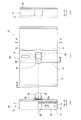
図1及び図2に示すように、この実施例の光ファイバ用コーナーガイド(以下、単にコーナーガイドともいう)10は、円筒の側面状の凸曲面12を有する一対のウイング14を備えている。両ウイング14間は、一段凹陥してクランプ保持溝(以下、単に保持溝ともいう)16が形成されている。
【0018】
保持溝16はウイング14に連続する一対の壁17と、両壁17間に配された底18とによって形成されている。
壁17の中央部には円弧状の凹部20が設けられている。また、壁17には、相手方の壁17に向かって突き出すように形成された抜け止め突起21が凹部20の両側に設けられている。抜け止め突起21は、図1(e)に拡大して示すとおり略山形であるが、保持溝16の開口側の傾斜は緩やかで底18側は急傾斜になっている。
【0019】
保持溝16の底18には保持溝16の片方の端部に寄った位置に長穴19が設けられている。また、底18の裏面には、スナップ23が連設されている。スナップ23の構造は周知のものと同様で、主軸板24と一対の斜板25とからなり、主軸板24の基部が底18から延出されている。
【0020】
周知のように、このスナップ23は、例えば板に開けられている穴に斜板25を主軸板24側に弾性変形させながら押し込むと、斜板25の先端部に設けられている階段状の係止部25aが穴の縁とかみ合い状態になり、また係止部25aと底18とで板を挟持して、この板と連結状態になる。したがって、スナップ23により、コーナーガイド10を板状の物体に装着、固定することができる。
【0021】
コーナーガイド10が板状の物体等に取り付けられていないときには(未使用状態では)、ウイング14の先端は底18の裏面よりもスナップ23側に位置する。このため、上記のようにスナップ23にてコーナーガイド10を板状の物体に装着、固定した際には、ウイング14の先端が板状の物体等に接触して、保持溝16の開口幅を狭めるように弾性変形する。この弾性変形は、保持溝16に嵌合したクランプ40(詳細は後述)をより強固に保持する力として作用する。
【0022】
なお、コーナーガイド10は、プラスチック材料(例えばポリプロピレン樹脂やナイロン樹脂など)の射出成形によって一体形成されている。
このコーナーガイド10は、光ファイバを配線する際に光ファイバを曲げる位置に設置しておき、光ファイバをウイング14に沿わせて配線することにより、光ファイバの曲がり部分の曲率を所定の曲率に維持できる。よって、光ファイバの曲率半径が小さくなりすぎて損傷されることを防止できる。
【0023】
このコーナーガイド10は、上記のように単独で使用してもよいのであるが、図3に例示するクランプ40と連結して使用するといっそう効果的である。
図3に示すように、クランプ40は、底部41及び一対の腕部42a、42bからなるクランプ本体43と、一対の腕部42a、42bに掛け渡されている可動ブリッジ44とで構成されており、クランプ本体43及び可動ブリッジ44は、それぞれプラスチック材料(例えばポリプロピレン樹脂やナイロン樹脂など)の射出成形によって一体形成されている。
【0024】
クランプ本体43の底部41の中央部にはビス孔45が貫通して設けられている。ビス孔45の周囲部分は底部41から弧状に突出して凸部47を形成している。また、底部41の両方の側面には外周リブ48が設けられており、その内側部分49との間に段差を形成している。そして、底部41の下面には腕部42a寄りに円柱状のピン状突起46が立設されている。
【0025】
底部41の厚み(側面の外周リブ48の端面距離)はコーナーガイド10の保持溝16の幅(壁17間距離)よりもわずかに小さく、凸部47の外形は壁17の凹部20の形状に整合し、ピン状突起46の径は長穴19の短径よりもわずかに小さい。
【0026】
したがって、図4に示すようにクランプ本体43の底部41をコーナーガイド10の保持溝16に嵌合させることが可能で、その嵌合時には凸部47が凹部20にはめ合い状態となる。このため、クランプ本体43を保持溝16に嵌合させた後は、凸部47と凹部20との位置ずれ即ちクランプ本体43が保持溝16の長さ方向にずれるのが防止される。なお、嵌合時にはピン状突起46は長穴19を貫通して突出する。
【0027】
また、底部41を保持溝16に嵌合させるために保持溝16の開口から押し込んだ際には、抜け止め突起21が外周リブ48に接触して抵抗となる。しかし、抜け止め突起21の傾斜が保持溝16の開口側では緩やかになっているから、底部41を強く押し込めば抜け止め突起21及び外周リブ48が弾性変形して外周リブ48を通過させる。一方、嵌合させた底部41を引き抜こうとしても、今度は抜け止め突起21の急傾斜が外周リブ48の通過を阻むので、この引き抜きは簡単ではない。つまり、抜け止め突起21が外周リブ48を係止する状態となってクランプ本体43の引き抜きを防止する。
【0028】
図3に示すように、腕部42a、42bの正面側には鋸歯状凹凸部51が設けられているが背面側には凹凸は設けられてはいない。
可動ブリッジ44の右端部は、鋸歯状凹凸部51の谷に対応する突起52aを備える歯合部52とかかる突起を有さないスライド部53とからなり、歯合部52とスライド部53とで腕部42bを挟み付けている。また左端部も同様の歯合部52とスライド部53とで構成されている。鋸歯状凹凸部51及び突起52aの形状は、可動ブリッジ44を下降させる力が加えられた際にはこれを阻まないが、上昇させる力が加えられた場合には可動ブリッジ44の移動を阻止する形状である。
【0029】
左右の歯合部52同士は弾性板55によって連結され、スライド部53同士はL字部材56によって連結されている。そして、弾性板55とL字部材56とは柔軟支点57にて連結されている。このため、弾性板55の「PRESS」の文字付近をL字部材56に押し付けるようにして弾性変形させると、柔軟支点57を中心にして歯合部52が変位し鋸歯状凹凸部51から離れる。これにより、可動ブリッジ44を上昇させることができる。
【0030】
腕部42bの上端は開放状態で歯合部52及びスライド部53の離脱を阻まないが、腕部42aの上端は円弧状のリブ58によって閉じられているので歯合部52及びスライド部53の離脱を阻止する。このため、可動ブリッジ44を上昇端にして腕部42bから歯合部52及びスライド部53を離脱させれば、リブ58付近を中心にして可動ブリッジ44を回動させることができる。
【0031】
従って、上記のようにして可動ブリッジ44を回動させて腕部42a、42bの先端部間を開放状態にして、クランプ本体43の腕部42a、42b間に光ファイバを通してから、可動ブリッジ44の一方の端部を腕部42bに装着して可動ブリッジ44を押し下げれば、光ファイバを可動ブリッジ44と底部41とで挟むようにして保持できる。つまり、光ファイバを結束状態にして保持できる。もちろん、1本の光ファイバでも保持できる。また、可動ブリッジ44を腕部42bから外さずに適宜上昇させた状態で光ファイバを通してもよい。
【0032】
以上のように、光ファイバ用コーナーガイド10は、クランプ保持溝16に保持されるクランプ40に設けられた凸部47に対応する凹部20をクランプ保持溝16の壁17に設けたことにより、クランプ保持溝16にクランプ40を保持した際に凸部47が凹部20にはめ合い状態となることでクランプ保持溝16の長さ方向に沿ったクランプ40の位置ずれを良好に防止できる。これにより、クランプ40内を通されている光ファイバの配線位置がずれるのも防止される。
【0033】
また、この光ファイバ用コーナーガイド10によれば、光ファイバをウイング14の凸曲面12に沿って配線することで光ファイバの曲率半径を適切な範囲に保持することができる。
クランプ保持溝16にクランプ40を嵌合させて、光ファイバをそのクランプ40内に通すことにより光ファイバを束線することができ、その際にクランプ40はクランプ保持溝16に保持されるので、クランプ40自体を固定するための手段は特に必要ない。しかも、クランプ40はクランプ保持溝16にはめ込まれるので、光ファイバ用コーナーガイド10とクランプ40との連結作業も簡単で、作業効率が低下するおそれもない。
【0034】
さらに、クランプ40の内側にコーナーガイド10が入り込まないから、クランプ40の束線許容量が減少することもない。
クランプ保持溝16にクランプ40を保持した際に、そのクランプ40に設けられたピン状突起46がクランプ保持溝16の底18に設けられた長穴19を貫通するので、その貫通したピン状突起46を、光ファイバ用コーナーガイド10が取り付けられた基板などの位置決め穴に嵌合させることが可能になる。
【0035】
この位置決め穴とピン状突起46との嵌合により、光ファイバ用コーナーガイド10が回り変位するのを防止できる。それによって、クランプ40内を通されている光ファイバの配線位置のずれも防止される。
また、長穴19であるので、クランプ40のサイズの違い等でピン状突起46の位置が変わっても対応できる。
【0036】
光ファイバ用コーナーガイド10は、クランプ保持溝16の壁17に設けられた抜け止め突起21が、クランプ保持溝16に嵌合したクランプ40の外周リブ48を係止するので、クランプ40がクランプ保持溝16から抜けるのを防止できる。
【0037】
また、光ファイバ用コーナーガイド10を基板などに取り付けた際には、ウイング14が弾性変形してクランプ保持溝16の開口幅を狭めるので、クランプ40をを保持する嵌合力が増し、クランプ40の抜け落ちやずれがさらに良好に防止される。
【0038】
【実施例2】
ビスを用いて基板などに固定する構造の光ファイバ用コーナーガイドを実施例2として説明する。
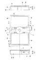
図5及び図6に示すように、この実施例の光ファイバ用コーナーガイド(以下、単にコーナーガイドともいう)50は、円筒の側面状の凸曲面62を有する一対のウイング64を備えている。両ウイング64間は、一段凹陥してクランプ保持溝(以下、単に保持溝という)56が形成されている。
【0039】
保持溝66はウイング64に連続する一対の壁67と、両壁67間に配された底68とによって形成されている。また、ウイング64と壁67の端部同士を連結するようにしてリブ65が設けられている。
壁67の中央部には円弧状の凹部70が設けられている。また、壁67には、相手方の壁67に向かって突き出すように形成された抜け止め突起71が凹部70の両側に設けられている。抜け止め突起71は、図5(e)に拡大して示すとおり略山形であるが、保持溝66の開口側の傾斜は緩やかで底68側は急傾斜になっている。
【0040】
保持溝66の底68には保持溝66の片方の端部に寄った位置に長穴69が設けられている。また、底68の中心部にはビス用の貫通穴73が設けられており、この貫通穴73に挿通させたビスにてコーナーガイド60を板状の物体等に螺着して、固定ができる。
【0041】
なお、コーナーガイド60は、プラスチック材料(例えばポリプロピレン樹脂やナイロン樹脂など)の射出成形によって一体形成されている。
このコーナーガイド60は、光ファイバを配線する際に光ファイバを曲げる位置に設置しておき、光ファイバをウイング64に沿わせて配線することにより、光ファイバの曲がり部分の曲率を所定の曲率に維持できる。よって、光ファイバの曲率半径が小さくなりすぎて損傷されることを防止できる。
【0042】
このコーナーガイド60は、上記のように単独で使用してもよいのであるが、図3に例示するクランプ40と連結して使用するといっそう効果的である。
クランプ40の構造などは実施例1にて説明したとおりである。
図7に示すように、クランプ本体43の底部41をコーナーガイド60の保持溝66に嵌合させることが可能で、その嵌合時にはビス孔45と貫通穴73とが同心で重なり合い、凸部47が凹部70にはめ合い状態となり、ピン状突起46は長穴69を貫通して突出する。
【0043】
このため、クランプ本体43を保持溝16に嵌合させた後は、凸部47と凹部70との位置ずれ即ちクランプ本体43が保持溝66の長さ方向にずれるのが防止される。
また、底部41を保持溝66に嵌合させるために保持溝66の開口から押し込んだ際には、抜け止め突起71が外周リブ48に接触して抵抗となる。しかし、抜け止め突起71の傾斜が保持溝66の開口側では緩やかになっているから、底部41を強く押し込めば抜け止め突起71及び外周リブ48が弾性変形して外周リブ48を通過させる。一方、嵌合させた底部41を引き抜こうとしても、今度は抜け止め突起71の急傾斜が外周リブ48の通過を阻むので、この引き抜きは簡単ではない。つまり、抜け止め突起71が外周リブ48を係止する状態となってクランプ本体43の引き抜きを防止する。
【0044】
ビス孔45と貫通穴73とが同心で重なり合うので、ビス孔45側から貫通穴73に挿通させたビスにて、クランプ40とコーナーガイド60とをとも締めして、それらを板状の物体等(例えば基板)に螺着して、固定ができる。
その際に、長穴69を貫通して突出しているピン状突起46を基板などの位置決め穴に嵌合させることによって、ビス締め時にコーナーガイド60が回り変位するのを防止でき、ビス締め作業を良好に行える。また、基板などの位置決め穴に嵌合したピン状突起46は、このようにして基板などに取り付けた後もコーナーガイド60が回り変位するのを防止するから、クランプ40内を通されている光ファイバの配線位置のずれも防止される。
【0045】
以上のように、光ファイバ用コーナーガイド60は、クランプ保持溝66に保持されるクランプ40に設けられた凸部47に対応する凹部70をクランプ保持溝66の壁67に設けたことにより、クランプ保持溝66にクランプ40を保持した際に凸部47が凹部70にはめ合い状態となることでクランプ保持溝66の長さ方向に沿ったクランプ40の位置ずれを良好に防止できる。これにより、クランプ40内を通されている光ファイバの配線位置がずれるのも防止される。
【0046】
また、この光ファイバ用コーナーガイド60によれば、光ファイバをウイング64の凸曲面62に沿って配線することで光ファイバの曲率半径を適切な範囲に保持することができる。
クランプ保持溝66にクランプ40を嵌合させて、光ファイバをそのクランプ40内に通すことにより光ファイバを束線することができ、その際にクランプ40はクランプ保持溝66に保持されるので、クランプ40自体を固定するための手段は特に必要ない。しかも、クランプ40はクランプ保持溝66にはめ込まれるので、光ファイバ用コーナーガイド60とクランプ40との連結作業も簡単で、作業効率が低下するおそれもない。
【0047】
さらに、クランプ40の内側にコーナーガイド60が入り込まないから、クランプ40の束線許容量が減少することもない。
クランプ保持溝66にクランプ40を保持した際には、クランプ40のビス孔45とコーナーガイド60の貫通穴73とが同心で重なり合うので、ビス孔45側から貫通穴73に挿通させたビスにて、クランプ40とコーナーガイド60とをとも締めして、それらを板状の物体等(例えば基板)に螺着して、固定ができる。
【0048】
また、クランプ40のピン状突起46がコーナーガイド60の長穴69を貫通するので、その貫通したピン状突起46を、光ファイバ用コーナーガイド60が取り付けられた基板などの位置決め穴に嵌合させることが可能になる。ピン状突起46を基板などの位置決め穴に嵌合させれば、ビス締め時にコーナーガイド60が回り変位するのを防止でき、ビス締め作業を良好に行える。また、基板などの位置決め穴に嵌合したピン状突起46は、このようにして基板などに取り付けた後もコーナーガイド60が回り変位するのを防止するから、クランプ40内を通されている光ファイバの配線位置のずれも防止される。
【0049】
また、長穴69であるので、クランプ40のサイズの違い等でピン状突起46の位置が変わっても対応できる。
光ファイバ用コーナーガイド60は、クランプ保持溝66の壁67に設けられた抜け止め突起71が、クランプ保持溝66に嵌合したクランプ40の外周リブ48を係止するので、クランプ40がクランプ保持溝66から抜けるのを防止できる。
【0050】
以上、2つの実施例に従って、本発明の実施の形態について説明したが、本発明はこれらのような例に限定されるものではなく、本発明の要旨を逸脱しない範囲でさまざまに実施できることは言うまでもない。
【図面の簡単な説明】
【図1】 実施例1の光ファイバ用コーナーガイドの説明図であり、(a)は平面図、(b)は正面図、(c)は(a)におけるA−A断面図、(d)は同B−B断面図、(e)は(d)のD部拡大図。
【図2】 実施例1の光ファイバ用コーナーガイドの説明図であり、(a)は裏面図、(b)は(a)におけるE−E矢視図、(c)は同C−C断面図。
【図3】 実施例1、2で使用したクランプの3面図。
【図4】 実施例1の光ファイバ用コーナーガイドにクランプを組み付けた状態の平面図。
【図5】 実施例2の光ファイバ用コーナーガイドの説明図であり、(a)は平面図、(b)は正面図、(c)は(a)におけるA−A断面図、(d)は同B−B断面図、(e)は(d)のD部拡大図。
【図6】 実施例2の光ファイバ用コーナーガイドの説明図であり、(a)は裏面図、(b)は(a)におけるE−E矢視図、(c)は同C−C断面図。
【図7】 実施例2の光ファイバ用コーナーガイドにクランプを組み付けた状態の平面図。
【符号の説明】
10 光ファイバ用コーナーガイド
12 凸曲面
14 ウイング
16 クランプ保持溝
17 壁
18 底
19 長穴
20 凹部
21 突起
23 スナップ
40 クランプ
41 底部
43 クランプ本体
44 可動ブリッジ
45 ビス孔
46 ピン状突起
47 凸部
48 外周リブ
60 光ファイバ用コーナーガイド
62 凸曲面
64 ウイング
65 リブ
66 クランプ保持溝
67 壁
68 底
69 長穴
70 凹部
71 突起
73 貫通穴[0001]
BACKGROUND OF THE INVENTION
The present invention belongs to the technical field of optical fiber corner guides and optical fiber holders.
[0002]
[Prior art]
Corner guides are used to prevent damage by keeping the curvature of the optical fiber in an appropriate range at the bent portion of the optical fiber. As an example, there is a corner guide for optical fiber of Japanese Patent No. 2823547.
[0003]
The corner guide for an optical fiber disclosed in Japanese Patent No. 2823547 includes a pair of wings having an arcuate convex curved surface in cross section, and a clamp holding groove formed between the wings so as to be recessed with respect to the convex curved surface. A main body part and a fixing means for attaching the main body part to another object are provided, and the main body part is attached to another object, such as a duct of an optical fiber.
[0004]
According to this optical fiber corner guide, the radius of curvature of the optical fiber can be maintained in an appropriate range by wiring the optical fiber along the convex curved surface of the wing. Further, for example, the optical fiber can be bundled by fitting the clamp into the clamp holding groove and passing the optical fiber through the clamp. At that time, the clamp is held in the clamp holding groove. There is no particular need for a means for fixing. In addition, since the clamp is fitted in the clamp holding groove, the connecting operation between the optical fiber corner guide and the clamp is easy, and there is no possibility that the working efficiency is lowered. Furthermore, since the corner guide does not enter the inside of the clamp, the allowable bundle amount of the clamp is not reduced.
[0005]
[Problems to be solved by the invention]
The corner guide for optical fiber of Japanese Patent No. 2823547 is excellent as described above, but there is room for improvement in terms of preventing the displacement of the clamp.
[0006]
[Means for Solving the Problems and Effects of the Invention]
An optical fiber holder according to
The front end of the wing is located on the opposite side of the clamp holding groove with respect to the bottom back surface of the clamp holding groove, and the bottom back surface of the clamp holding groove is in contact with the other object. When a corner guide is attached to the other object, an optical fiber corner guide that elastically deforms so that the tip of the wing comes into contact with the other object and narrows the opening width of the clamp holding groove ;
A clamp held in the clamp holding groove,
By providing a convex portion on one of the wall of the clamp holding groove and the clamp, and providing a concave portion corresponding to the convex portion on the other,
When the clamp is held in the clamp holding groove, the convex portion is fitted to the concave portion, thereby preventing the displacement of the clamp along the length direction of the clamp holding groove.
It is characterized by that.
When the clamp is held in the clamp holding groove, the convex portion fits into the concave portion, so that the displacement of the clamp along the length direction of the clamp holding groove can be prevented . It is possible to satisfactorily prevent the clamp from being displaced in the length direction of the clamp holding groove. Thereby, it is also prevented that the wiring position of the optical fiber passing through the clamp is shifted.
[0007]
Further, according to this optical fiber corner guide, the radius of curvature of the optical fiber can be maintained in an appropriate range by wiring the optical fiber along the convex curved surface of the wing.
For example, the optical fiber can be bundled by fitting the clamp into the clamp holding groove and passing the optical fiber through the clamp. At that time, the clamp is held in the clamp holding groove, so the clamp itself is fixed. There is no particular need for means to do this. In addition, since the clamp is fitted in the clamp holding groove, the connecting operation between the optical fiber corner guide and the clamp is easy, and there is no possibility that the working efficiency is lowered.
[0008]
Furthermore, since the corner guide does not enter the inside of the clamp, the allowable bundle amount of the clamp is not reduced.
In addition, the corner guide for optical fibers can be used alone, and even in that case, the radius of curvature of the optical fiber can be maintained in an appropriate range by wiring the optical fiber along the convex curved surface of the wing.
[0009]
In addition, since the elastic deformation of the optical fiber corner guide acts as a force for firmly holding the clamp fitted in the clamp holding groove, the clamp held in the clamp holding groove is displaced in the length direction of the clamp holding groove. Can be prevented well. Thereby, it is also prevented that the wiring position of the optical fiber passing through the clamp is shifted.
The optical fiber holder according to
[0010]
When the clamp is held in the clamp holding groove, the pin-shaped protrusion provided in the clamp penetrates the long hole provided in the bottom of the clamp holding groove. Can be fitted into a positioning hole such as a substrate to which is attached.
[0011]
The fitting between the positioning hole and the pin-shaped protrusion can prevent the optical fiber corner guide from rotating and displacing. Thereby, the displacement of the wiring position of the optical fiber passing through the clamp is also prevented.
Moreover, since it is a long hole, it can respond even if the position of the pin-shaped protrusion changes due to a difference in the size of the clamp.
[0012]
The optical fiber holder according to
[0013]
The optical fiber holder according to
Since the through hole is provided at the center of the bottom of the clamp holding groove, it is suitable for a usage method of fixing the corner guide for optical fiber to a substrate or the like using a screw.
[0015]
Also, since the clamp is provided with a screw hole that overlaps with the through hole when held in the clamp holding groove, the optical fiber corner guide and the clamp are connected by the single screw passed through the through hole and the screw hole. It can be fastened together and fixed to the substrate.
[0016]
DETAILED DESCRIPTION OF THE INVENTION
Next, embodiments of the present invention will be described by way of some examples of the present invention.
[0017]
[Example 1]
As shown in FIGS. 1 and 2, an optical fiber corner guide (hereinafter, also simply referred to as a corner guide) 10 of this embodiment includes a pair of
[0018]
The holding
An arc-shaped
[0019]
An
[0020]
As is well known, when the
[0021]
When the
[0022]
The
The
[0023]
Although the
As shown in FIG. 3, the
[0024]
A
[0025]
The thickness of the bottom portion 41 (the end surface distance of the outer peripheral rib 48 on the side surface) is slightly smaller than the width of the holding
[0026]
Therefore, as shown in FIG. 4, the bottom 41 of the
[0027]
Further, when the bottom 41 is pushed into the holding
[0028]
As shown in FIG. 3, a serrated uneven portion 51 is provided on the front side of the arms 42a and 42b, but no unevenness is provided on the back side.
The right end portion of the movable bridge 44 includes a
[0029]
The left and
[0030]
The upper end of the arm portion 42b is in an open state and does not block the separation of the meshing
[0031]
Therefore, the movable bridge 44 is rotated as described above so that the end portions of the arm portions 42a and 42b are opened, and an optical fiber is passed between the arm portions 42a and 42b of the
[0032]
As described above, the optical
[0033]
Further, according to the optical
The optical fiber can be bundled by fitting the
[0034]
Furthermore, since the
When the
[0035]
The fitting between the positioning hole and the pin-shaped
Moreover, since it is the
[0036]
In the optical
[0037]
Further, when the optical
[0038]
[Example 2]
An optical fiber corner guide having a structure that is fixed to a substrate or the like using screws will be described as a second embodiment.
As shown in FIGS. 5 and 6, the optical fiber corner guide (hereinafter, also simply referred to as a corner guide) 50 of this embodiment includes a pair of
[0039]
The holding
An
[0040]
An
[0041]
The
The
[0042]
Although the
The structure of the
As shown in FIG. 7, the bottom 41 of the
[0043]
For this reason, after the clamp
Further, when the bottom portion 41 is pushed into the holding
[0044]
Since the
At that time, the pin-
[0045]
As described above, the optical
[0046]
Moreover, according to this corner guide 60 for optical fibers, the curvature radius of an optical fiber can be hold | maintained in an appropriate range by wiring an optical fiber along the
The optical fiber can be bundled by fitting the
[0047]
Further, since the
When the
[0048]
Further, since the pin-
[0049]
Moreover, since it is the
In the optical
[0050]
Although the embodiments of the present invention have been described according to the two examples, it is needless to say that the present invention is not limited to these examples and can be implemented in various ways without departing from the gist of the present invention. Yes.
[Brief description of the drawings]
1A and 1B are explanatory views of a corner guide for an optical fiber according to a first embodiment, where FIG. 1A is a plan view, FIG. 1B is a front view, FIG. 1C is a cross-sectional view taken along line AA in FIG. Is a cross-sectional view taken along the line B-B, and (e) is an enlarged view of a portion D in (d).
2A and 2B are explanatory views of a corner guide for an optical fiber according to a first embodiment, where FIG. 2A is a rear view, FIG. 2B is a view taken along the line EE in FIG. Figure.
FIG. 3 is a three-side view of a clamp used in Examples 1 and 2.
4 is a plan view of a state where a clamp is assembled to the corner guide for optical fiber according to
5A and 5B are explanatory views of a corner guide for an optical fiber according to a second embodiment, where FIG. 5A is a plan view, FIG. 5B is a front view, FIG. 5C is a cross-sectional view taken along line AA in FIG. Is a cross-sectional view taken along the line B-B, and (e) is an enlarged view of a portion D in (d).
6A and 6B are explanatory views of a corner guide for an optical fiber according to a second embodiment, where FIG. 6A is a rear view, FIG. 6B is a view taken along the line EE in FIG. Figure.
7 is a plan view showing a state where a clamp is assembled to the corner guide for optical fiber according to
[Explanation of symbols]
DESCRIPTION OF
Claims (4)
該ウイング間に前記凸曲面に対して凹陥して形成されるクランプ保持溝とを備える本体部と、
該本体部を他の物体に取付けるための固定手段とを備える光ファイバ用コーナーガイドであり、
前記ウイングの先端は前記クランプ保持溝の底裏面を基準にして前記クランプ保持溝とは反対側に位置しており、
前記クランプ保持溝の底裏面を前記他の物体に接触させて該光ファイバ用コーナーガイドを前記他の物体に取付けると、前記ウイングの先端が該他の物体に接触して、前記クランプ保持溝の開口幅を狭めるように弾性変形する
光ファイバ用コーナーガイドと、
前記クランプ保持溝に保持されるクランプとからなり、
前記クランプ保持溝の壁と前記クランプとの一方に凸部を設け、他方には該凸部に対応する凹部を設けたことにより、
前記クランプ保持溝に前記クランプを保持した際に前記凸部が前記凹部にはめ合い状態となることで前記クランプ保持溝の長さ方向に沿った前記クランプの位置ずれを防止可能とした
ことを特徴とする光ファイバ保持具。A pair of wings in which the outer shape of the cross section is an arc-shaped convex curved surface;
A main body provided with a clamp holding groove formed to be recessed with respect to the convex curved surface between the wings;
A corner guide for an optical fiber comprising a fixing means for attaching the main body to another object ,
The tip of the wing is located on the opposite side of the clamp holding groove with respect to the bottom back surface of the clamp holding groove,
When the optical fiber corner guide is attached to the other object by bringing the bottom back surface of the clamp holding groove into contact with the other object, the tip of the wing contacts the other object, and the clamp holding groove An optical fiber corner guide that is elastically deformed to narrow the opening width ;
A clamp held in the clamp holding groove,
By providing a convex portion on one of the wall of the clamp holding groove and the clamp, and providing a concave portion corresponding to the convex portion on the other,
When the clamp is held in the clamp holding groove, the convex portion is fitted to the concave portion, thereby preventing the displacement of the clamp along the length direction of the clamp holding groove.
An optical fiber holder characterized by that .
前記クランプにピン状突起を設け、
短径が前記クランプ保持溝の幅方向に沿い長径が該クランプ保持溝の長さ方向に沿い、前記ピン状突起を貫通させる長穴を前記クランプ保持溝の底の中心から外れる位置に設けた
ことを特徴とする光ファイバ保持具。The optical fiber holder according to claim 1, wherein
Provide a pin-like protrusion on the clamp,
The long diameter is along the width direction of the clamp holding groove and the long diameter is along the length direction of the clamp holding groove, and a long hole that penetrates the pin-like protrusion is provided at a position that is off the center of the bottom of the clamp holding groove. An optical fiber holder characterized by the above.
前記クランプ保持溝に保持した前記クランプが前記クランプ保持溝の底から離れる方向へ移動するのを阻む抜け止め突起を、前記クランプ保持溝の壁に設けた
ことを特徴とする光ファイバ保持具。The optical fiber holder according to claim 1 or 2 ,
An optical fiber , wherein a retaining protrusion that prevents the clamp held in the clamp holding groove from moving in a direction away from the bottom of the clamp holding groove is provided on a wall of the clamp holding groove. Retaining tool.
前記クランプ保持溝の底の中心部に貫通穴が設けられ、
前記クランプには、前記クランプ保持溝に保持されたときに前記貫通穴と重なり合うビス穴が設けられている
ことを特徴とする光ファイバ保持具。The optical fiber holder according to any one of claims 1 to 3 ,
A through hole is provided at the center of the bottom of the clamp holding groove,
The optical fiber holder , wherein the clamp is provided with a screw hole that overlaps the through hole when held in the clamp holding groove .
Priority Applications (1)
| Application Number | Priority Date | Filing Date | Title |
|---|---|---|---|
| JP2002002473A JP3787308B2 (en) | 2002-01-09 | 2002-01-09 | Optical fiber holder |
Applications Claiming Priority (1)
| Application Number | Priority Date | Filing Date | Title |
|---|---|---|---|
| JP2002002473A JP3787308B2 (en) | 2002-01-09 | 2002-01-09 | Optical fiber holder |
Publications (3)
| Publication Number | Publication Date |
|---|---|
| JP2003202428A JP2003202428A (en) | 2003-07-18 |
| JP2003202428A5 JP2003202428A5 (en) | 2005-11-10 |
| JP3787308B2 true JP3787308B2 (en) | 2006-06-21 |
Family
ID=27642319
Family Applications (1)
| Application Number | Title | Priority Date | Filing Date |
|---|---|---|---|
| JP2002002473A Expired - Fee Related JP3787308B2 (en) | 2002-01-09 | 2002-01-09 | Optical fiber holder |
Country Status (1)
| Country | Link |
|---|---|
| JP (1) | JP3787308B2 (en) |
Families Citing this family (2)
| Publication number | Priority date | Publication date | Assignee | Title |
|---|---|---|---|---|
| JP6045931B2 (en) * | 2013-02-08 | 2016-12-14 | Nds株式会社 | Cable pull-in support device |
| CN109058247B (en) * | 2018-08-13 | 2023-10-03 | 珠海格力电器股份有限公司 | Fixed briquetting and air conditioning unit |
-
2002
- 2002-01-09 JP JP2002002473A patent/JP3787308B2/en not_active Expired - Fee Related
Also Published As
| Publication number | Publication date |
|---|---|
| JP2003202428A (en) | 2003-07-18 |
Similar Documents
| Publication | Publication Date | Title |
|---|---|---|
| US7445493B2 (en) | Connector for a flexible conductor | |
| US5740640A (en) | Clip for door molding | |
| JP5544019B2 (en) | Cam lock buckle | |
| US4924561A (en) | Single-fin fastener | |
| EP1986251B1 (en) | Battery device | |
| KR20070037371A (en) | Electrical connector for flat cable | |
| KR20070051358A (en) | U-shaped clamp | |
| WO2017134766A1 (en) | Sealing structure and electricity meter | |
| JP3787308B2 (en) | Optical fiber holder | |
| JP2007523277A (en) | Fixing device for slide or guide channel | |
| TWI229476B (en) | Electrical connector | |
| JP3788544B2 (en) | Optical fiber holder | |
| JP3702087B2 (en) | Hinge mounting device | |
| JP2000348820A (en) | Connector supporting mechanism | |
| CN215006020U (en) | Optical cable terminal box | |
| JP5030505B2 (en) | Window regulator | |
| JPH0339593Y2 (en) | ||
| JP3697238B2 (en) | Articulated duct | |
| CN218450885U (en) | LED drive power supply shell structure | |
| CN211846260U (en) | Clamping device | |
| US20230208119A1 (en) | Fixture mounting structure and resin fixture | |
| JP4242224B2 (en) | Vehicle sun visor | |
| JP2004135436A (en) | Locking structure for corrugated tube | |
| JPH0597077U (en) | Connector for plate cable | |
| JPH06274771A (en) | Self-locking terminal equipment for fire sensor |
Legal Events
| Date | Code | Title | Description |
|---|---|---|---|
| A621 | Written request for application examination |
Free format text: JAPANESE INTERMEDIATE CODE: A621 Effective date: 20040720 |
|
| A977 | Report on retrieval |
Free format text: JAPANESE INTERMEDIATE CODE: A971007 Effective date: 20050714 |
|
| A521 | Written amendment |
Free format text: JAPANESE INTERMEDIATE CODE: A523 Effective date: 20050928 |
|
| A131 | Notification of reasons for refusal |
Free format text: JAPANESE INTERMEDIATE CODE: A131 Effective date: 20051011 |
|
| A521 | Written amendment |
Free format text: JAPANESE INTERMEDIATE CODE: A523 Effective date: 20051202 |
|
| A131 | Notification of reasons for refusal |
Free format text: JAPANESE INTERMEDIATE CODE: A131 Effective date: 20060110 |
|
| A521 | Written amendment |
Free format text: JAPANESE INTERMEDIATE CODE: A523 Effective date: 20060220 |
|
| TRDD | Decision of grant or rejection written | ||
| A01 | Written decision to grant a patent or to grant a registration (utility model) |
Free format text: JAPANESE INTERMEDIATE CODE: A01 Effective date: 20060314 |
|
| A61 | First payment of annual fees (during grant procedure) |
Free format text: JAPANESE INTERMEDIATE CODE: A61 Effective date: 20060324 |
|
| R150 | Certificate of patent or registration of utility model |
Free format text: JAPANESE INTERMEDIATE CODE: R150 |
|
| FPAY | Renewal fee payment (event date is renewal date of database) |
Free format text: PAYMENT UNTIL: 20090331 Year of fee payment: 3 |
|
| FPAY | Renewal fee payment (event date is renewal date of database) |
Free format text: PAYMENT UNTIL: 20100331 Year of fee payment: 4 |
|
| FPAY | Renewal fee payment (event date is renewal date of database) |
Free format text: PAYMENT UNTIL: 20100331 Year of fee payment: 4 |
|
| FPAY | Renewal fee payment (event date is renewal date of database) |
Free format text: PAYMENT UNTIL: 20110331 Year of fee payment: 5 |
|
| FPAY | Renewal fee payment (event date is renewal date of database) |
Free format text: PAYMENT UNTIL: 20120331 Year of fee payment: 6 |
|
| FPAY | Renewal fee payment (event date is renewal date of database) |
Free format text: PAYMENT UNTIL: 20120331 Year of fee payment: 6 |
|
| FPAY | Renewal fee payment (event date is renewal date of database) |
Free format text: PAYMENT UNTIL: 20120331 Year of fee payment: 6 |
|
| FPAY | Renewal fee payment (event date is renewal date of database) |
Free format text: PAYMENT UNTIL: 20130331 Year of fee payment: 7 |
|
| FPAY | Renewal fee payment (event date is renewal date of database) |
Free format text: PAYMENT UNTIL: 20130331 Year of fee payment: 7 |
|
| FPAY | Renewal fee payment (event date is renewal date of database) |
Free format text: PAYMENT UNTIL: 20130331 Year of fee payment: 7 |
|
| FPAY | Renewal fee payment (event date is renewal date of database) |
Free format text: PAYMENT UNTIL: 20130331 Year of fee payment: 7 |
|
| FPAY | Renewal fee payment (event date is renewal date of database) |
Free format text: PAYMENT UNTIL: 20140331 Year of fee payment: 8 |
|
| S531 | Written request for registration of change of domicile |
Free format text: JAPANESE INTERMEDIATE CODE: R313531 |
|
| R350 | Written notification of registration of transfer |
Free format text: JAPANESE INTERMEDIATE CODE: R350 |
|
| R250 | Receipt of annual fees |
Free format text: JAPANESE INTERMEDIATE CODE: R250 |
|
| R250 | Receipt of annual fees |
Free format text: JAPANESE INTERMEDIATE CODE: R250 |
|
| R250 | Receipt of annual fees |
Free format text: JAPANESE INTERMEDIATE CODE: R250 |
|
| LAPS | Cancellation because of no payment of annual fees |