JP3785230B2 - Double integrated heat exchanger - Google Patents
Double integrated heat exchanger Download PDFInfo
- Publication number
- JP3785230B2 JP3785230B2 JP24819496A JP24819496A JP3785230B2 JP 3785230 B2 JP3785230 B2 JP 3785230B2 JP 24819496 A JP24819496 A JP 24819496A JP 24819496 A JP24819496 A JP 24819496A JP 3785230 B2 JP3785230 B2 JP 3785230B2
- Authority
- JP
- Japan
- Prior art keywords
- exchange medium
- heat exchange
- medium flow
- heat exchanger
- plate
- Prior art date
- Legal status (The legal status is an assumption and is not a legal conclusion. Google has not performed a legal analysis and makes no representation as to the accuracy of the status listed.)
- Expired - Fee Related
Links
Images


Description
【0001】
【発明の属する技術分野】
この発明は、例えば、コンデンサーとラジエーターなどのように、相互に種類の異なる複数の熱交換器が一体的に構成された複式一体型熱交換器に関する。
【0002】
【従来の技術】
例えば、エンジン冷却用のラジエーターとカーエアコン用のコンデンサーとが一体的に構成された複式一体型熱交換器として、次のような熱交換器が提案されている。
【0003】
即ち、この複式一体型熱交換器は、一対の皿状成形プレートが対向状に重ね合わされて、内部に、第1及び第2の幅方向に2つの偏平な熱交換媒体流通路が互いに独立して形成された帯板状チューブエレメントを複数枚備えており、該帯板状チューブエレメントが、それらの間に両端部を除いてアウターフィンを介在させて、厚さ方向に積層されている。そして、帯板状チューブエレメントを構成する皿状成形プレートの両端部には、第1熱交換媒体流通路に対応して外方膨出状の第1ヘッダー部が絞り加工により一体成形されると共に、第2熱交換媒体流通路に対応して外方膨出状の第2ヘッダー部が同じく絞り加工により一体成形され、隣り合うチューブエレメントが、第1ヘッダー部同士、第2ヘッダー部同士を連通接続して、互いに独立した第1及び第2の2つの熱交換器が一体的に形成され、一方の熱交換器をラジエーターとし、もう一方の熱交換器をコンデンサーとする構成となされている(特願平7−63052号)。
【0004】
【発明が解決しようとする課題】
しかしながら、上記のような構成の複式一体型熱交換器では、コンデンサーとして用いられる方の熱交換器に、耐圧強度上の問題を生じる場合があった。即ち、軽量化等を図る目的において、帯板状チューブエレメントを構成する皿状成形プレートは、可及的薄肉に成形されており、そのため、皿状成形プレートの両端部に絞り加工によって一体成形される膨出状ヘッダー部も成形プレート本体部と同様に非常に薄肉なものになってしまう。そのため、コンデンサーとして用いる方の熱交換器において、その膨出状ヘッダー部において耐圧強度の不足を生じる場合があった。
【0005】
そこで、膨出状ヘッダー部にかかる応力を減少させるべく膨出状ヘッダー部のサイズを小さくすることも考えられるが、それでは、帯板状チューブエレメント内の熱交換媒体流通路の幅方向における熱交換媒体の分配が十分でなくなったり、また絞り加工が技術的に非常に難しくなってしまう等の問題を派生する。
【0006】
また、膨出状ヘッダー部をテーラーブランキング等により重ね絞り成形することも考えられるが、それでは、部分的に板厚違いがあるため、金型の製作、精度確保が難しく、また重ね部分の洗浄ができないなどの問題を派生する。
【0007】
本発明は、上記のような技術背景のもとで、このような問題を派生させることなく、複数形成された熱交換器のうちの少なくとも1つの高耐圧が求められる熱交換器について、皿状成形プレートの肉厚を薄いものにしながら、隣り合う帯板状チューブエレメントの対応熱交換媒体流通路同士を内部的に連通させる部分の耐圧強度を向上することができる複式一体型熱交換器を提供することを課題とする。
【0008】
【課題を解決するための手段】
上記課題は、一対の皿状成形プレートが対向状に重ね合わされて、内部に、偏平な熱交換媒体流通路が幅方向に複数、互いに独立して形成された帯板状チューブエレメントを複数枚備え、該帯板状チューブエレメントが、それらの間に両端部を除いてアウターフィンを介在させて、厚さ方向に積層され、前記帯板状チューブエレメント間の両端部において、帯板状チューブエレメントの各熱交換媒体流通路が、隣り合う帯板状チューブエレメントの対応熱交換媒体流通路にそれぞれ内部的に連通されることにより、互いに独立した複数の熱交換器が一体的に形成された複式一体型熱交換器であって、前記各帯板状チューブエレメントに形成された複数の熱交換媒体流通路のうちの少なくとも1つの対応熱交換媒体流通路同士が、隣り合う帯板状チューブエレメント間の両端部に配置された、帯板状チューブエレメントとは別体の短筒状の連通パイプを通じて内部的に連通されてなることを特徴とする複式一体型熱交換器によって解決される。
【0009】
即ち、上記構成では、各帯板状チューブエレメントに形成された複数の熱交換媒体流通路のうちの少なくとも1つの対応熱交換媒体流通路同士が、隣り合う帯板状チューブエレメント間の両端部に配置された、帯板状チューブエレメントとは別体の短筒状の連通パイプを通じて、内部的に連通されたものであることにより、帯板状チューブエレメントを構成する皿状成形プレートの肉厚を薄くしつつ、短筒状の連通パイプを厚肉に設計することができ、このパイプ連通された熱交換媒体流通路郡から構成される熱交換器については、隣り合う帯板状チューブエレメントの熱交換媒体流通路同士を内部的に連通させる部分の耐圧強度が向上され、高い耐圧性能が発揮される。
【0010】
また、前記複式一体型熱交換器において、チューブエレメントを構成する成形プレートの内面に形成された第1熱交換媒体通路用の凹部の底壁部は、両端を半円弧状とする平面視長円状をなし、底壁部の両端部に、円形の第1熱交換媒体流通孔が形成されていても良い。
【0011】
また、短筒状連通パイプは、チューブエレメント間の間隔距離に対応する長さの円形パイプ材によるもので、短筒状連通パイプの周壁の肉厚は、皿状成形プレートの肉厚よりも厚肉に設定され、それ単独で内部圧力に耐え得る耐圧強度を備えている構成としても良い。
【0012】
また、短筒状連通パイプは、その両端部が、隣り合うチューブエレメントの対向する成形プレートの位置決め用バーリング部に外嵌め状態に適合して嵌合され、ブレージングシートのろう材にて接合一体化され、隣り合うチューブエレメントの第1熱交換媒体流通路を内部的に連通していても良い。
【0013】
また、各チューブエレメントの第1熱交換媒体流通路内に、インナーフィンが配置されていても良い。
【0014】
また、インナーフィンの両端部には、成形プレートの第1熱交換媒体流通孔と同じサイズの熱交換媒体流通孔が形成されており、この熱交換媒体流通孔が前記成形プレートの第1熱交換媒体流通孔と同芯状に配置されていても良い。
【0015】
また、インナーフィンの両端部に、熱交換媒体流通孔を省略されて、半円状の凹部が形成され、半円状凹部が第1円形熱交換媒体流通孔と同芯状に配置されていても良い。
【0016】
また、第1熱交換媒体流通路を形成する長円状凹部の両端部の半円状の周壁から第1熱交換媒体流通孔側に隆起状の三角形状リブが突出して形成され、このリブがもう一方の皿状成形プレートの対応リブにブレージングシートのろう材にて接合一体化されていても良い。
【0017】
また、インナーフィンの両端部に半円状の凹部が形成され、この半円状凹部が円形の第1熱交換媒体流通孔と同芯状に配置され、第1熱交換媒体流通路を形成する長円状凹部の両端部底壁の、インナーフィンの存在しない部分に、複数ない しは多数の小突起状のリブが分散状態に形成され、これらのリブの先端部がもう一方の皿状成形プレートの対応リブ又は底壁部にブレージングシートのろう材にて接合一体化されていても良い。
【0018】
また、インナーフィンの両端部が長さ方向と直角に切断され、インナーフィンの端部が、成形プレートの第1熱交換媒体流通孔の手前に位置するものとなされ、第1熱交換媒体流通路を形成する長円状凹部の両端部底壁の、インナーフィンの存在しない部分に、前記第1熱交換媒体流通孔の周囲部分を含めて、複数ないしは多数の小突起状のリブが分散状態に形成され、これらのリブの先端部がもう一方の皿状成形プレートの対応リブ又は底壁部にブレージングシートのろう材にて接合一体化されていても良い。
【0019】
また、各チューブエレメントの第2熱交換媒体流通路内にも、インナーフィンが配置された構成としても良い。
【0020】
また、インナーフィンが、熱交換媒体通路を区画する仕切り壁の適宜箇所に孔、スリット、ルーバー等が形成されたパーフォレートタイプであっても良いし、あるいは熱交換媒体通路を区画する仕切り壁を所定長毎にチューブの幅方向に位相を異にした状態で設けたオフセットタイプであっても良い。
【0021】
また、第1熱交換媒体流通路と第2熱交換媒体流通路の間において、チューブエレメントに断熱用のスリット開口部が形成されていても良い。
【0022】
また、チューブエレメントに形成された複数の熱交換媒体流通路の全てにおける各対応熱交換媒体流通路同士が、連通パイプを通じて内部的に連通されてなる構成としても良い。
【0023】
また、独立した複数の熱交換器が、エンジン冷却用のラジエーターとカーエアコン用のコンデンサーの組み合わせであっても良いし、コンデンサーとコンデン サーの組み合わせであっても良いし、コンデンサーとインタークーラーの組み合わせであっても良いし、コンデンサーとエンジンオイルクーラーの組み合わせであっても良い。
【0024】
また、独立した複数の熱交換器を3つ以上備えていても良い。
【0025】
【発明の実施の形態】
次に、本発明の複式一体型熱交換器の実施形態を図面に基づいて説明する。
【0026】
本実施形態の複式一体型熱交換器は、エンジン冷却用のラジエーターと、カーエアコン用のコンデンサーとを一体的に備えたものである。
【0027】
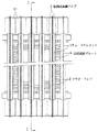
図1ないし図7に示される実施形態にかかる複式一体型熱交換器において、(1)…は帯板状チューブエレメント、(2)はアウターフィン、(3)は短筒状連通パイプである。
【0028】
図1に示されるように、この複式一体型熱交換器において、帯板状チューブエレメント(1)…は複数枚備えられ、それらの間に両端部を除いてアウターフィン(2)を介在させて、厚さ方向に積層されている。
【0029】
各帯板状チューブエレメント(1)は、一対の皿状成形プレート(4)(4)が対向状に重ね合わされて構成されたものである。各皿状成形プレート(4)は、芯材の両面にろう材層がクラッドされた薄板状のアルミニウムブレージングシートのプレス成形品からなり、このろう材によって全体が一括ろう付けにより接合一体化されている。
【0030】
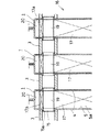
図7に示されるように、各皿状成形プレート(4)の内面部には、幅方向の一方の側にコンデンサー用の第1熱交換媒体通路を形成する凹部(5)が長手方向に延びて形成されると共に、幅方向のもう一方の側にはラジエーター用の第2熱交換媒体通路を形成する凹部(6)が、前記コンデンサー用凹部(5)とは独立して長手方向に延びて形成され、両皿状成形プレート(4)(4)が重ね合わされて上記ブレージングシートのろう材にて一括ろう付け接合されることにより、図2に示されるように、幅方向に2つの互いに独立したコンデンサー用の第1の熱交換媒体流通路(7)とラジエーター用の第2の熱交換媒体流通路(9)がそれぞれ形成されている。なお、(27)は断熱用のスリット開口部である。
【0031】
上記帯板状チューブエレメント(1)において、その両端部には、ラジエーター用の第2熱交換媒体流通路(9)に対応して、この第2熱交換媒体流通路(9)と内部連通する外方膨出状のヘッダー部(11)(11)が絞り加工にて一体成形されている。各膨出状ヘッダー部(11)は、図6に示されるように、帯板状チューブエレメント(1)を構成する各皿状成形プレート(4)(4)の第2熱交換媒体通路を形成する凹部(6)に対応して、その両端部に該凹部(6)と連続して該凹部(6)よりも深い凹部(12)が絞り加工にて一体成形され、両皿状成形プレート(4)(4)が重ね合わされて形成されたものである。該膨出状ヘッダー部(11)(11)の両面には、第2熱交換媒体流通孔(13)(13)が形成され、隣り合う帯板状チューブエレメント(1)(1)の膨出状ヘッダー部(11)(11)同士が上記ブレージングシートのろう材にて一括ろう付けされて接続されることにより、隣り合うチューブエレメント(1)(1)の第2熱交換媒体流通路(9)(9)が互いに該熱交換媒体流通孔(13)を通じて内部連通され、ラジエーター用の第2熱交換器(14)が形成されている。
【0032】
一方、上記帯板状チューブエレメント(1)を構成する各皿状成形プレート(4)において、その内面に形成されたコンデンサー用凹部(5)の底壁部(5a)は、図7に示されるように、両端を半円弧状とする平面視長円状をなし、該底壁部(5a)の両端部に、円形の第1熱交換媒体流通孔(15)が形成されている。なお、図4に示されるように、第1熱交換媒体流通孔(15)の周縁部には外方突出状のパイプ位置決め用バーリング部(15a )が形成されている。そして、隣り合う帯板状チューブエレメント(1)(1)の第1熱交換媒体流通路(7)(7)同士が該第1熱交換媒体流通孔(15)(15)を通して内部的に連通されることにより、第1熱交換媒体流通路(7)…の郡からなるコンデンサー用の第1熱交換器(16)が形成されるが、この連通のため、帯板状チューブエレメント(1)とは別体の短筒状連通パイプ(3)が用いられている。
【0033】
短筒状連通パイプ(3)は、図1及び図4に示されるように、帯板状板状チューブエレメント(1)…間の間隔距離に対応する長さの円形パイプ材によるもので、アルミニウム製の中空押出型材を所定長さに切断して製作されたものである。該短筒状連通パイプ(3)の周壁の肉厚は、熱交換中に該短筒状連通パイプ(3)にかかる圧力を考慮し、皿状成形プレートの肉厚よりも厚肉に設定され、それ単独で内部圧力に耐え得る耐圧強度を備えたものに設計されている。
【0034】
この短筒状連通パイプ(3)は、その両端部が、隣り合う帯板状チューブエレメント(1)(1)の対向する皿状成形プレート(4)(4)の位置決め用バーリング部(15a )(15a )に外嵌め状態に適合して嵌合され、上記ブレージングシートのろう材にて接合一体化され、それによって、隣り合う帯板状チューブエレメント(1)(1)の第1熱交換媒体流通路(7)(7)を内部的に連通している。そしてそれにより、第1熱交換媒体流通路(7)…の群からなるコンデンサー用の第1熱交換器(16)を形成している。
【0035】
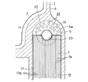
本実施形態では、各帯板状チューブエレメント(1)内の第1熱交換媒体流通路(7)内に、インナーフィン(17)が配置されている。このインナーフィン(17)は、図5に示されるように、アルミニウム製の薄板材を横断面矩形波形状にプレス成形して製作されたもので、その幅は、第1熱交換媒体流通路(7)の幅とほぼ一致するものに設計されており、帯板状チューブ(1)内に幅方向に合致状態に配置されて、その各波形頂部において、皿状成形プレート(4)の第1熱交換媒体流通路(7)を形成する凹部(5)の底壁部(5a)の内面に上記ブレージングシートのろう材にて一括ろう付け接合され、両皿状成形プレート(4)(4)を連結している。これにより、帯板状チューブ(1)の第1熱交換媒体流通路(7)側の耐圧強度が高められると共に、該第1熱交換媒体流通路(7)を幅方向に複数の単位通路(7a)…に区画して熱交換媒体流通路(7)の流体直径を小さくし熱交換効率を向上している。
【0036】
該インナーフィン(17)の両端部には、図2及び図3に示されるように、第1熱交換媒体流通孔(15)(15)と同じサイズの円形の熱交換媒体流通孔(19)が形成されており、該熱交換媒体流通孔(19)が皿状成形プレート(4)の第1熱交換媒体流通路(7)側の熱交換媒体流通孔(15)と同芯状に配置されている。
【0037】
そして、該インナーフィン(17)の両端部は、図3に示されるように、第1熱交換媒体流通路(7)の両端部周囲を囲む半円弧状内端部よりも径小な半円弧状突出部(17a )を有するものに形成されており、該半円弧状突出部(17a )が第1熱交換媒体流通路(7)の両端部周囲を囲む半円弧状内端部から離間されて、それらの間にインナーフィン(17)の存在しない半円弧状の空間部(20)が形成され、該空間部(20)を介して、第1熱交換媒体流通路(7)の各単位通路(7a)…が相互に連通されるようになされている。
【0038】
なお、図2に示されるように、各帯板状チューブエレメント(1)内のラジエーター用第2熱交換媒体流通路(9)内にも、インナーフィン(21)が配置され、同様に、帯板状チューブ(1)の第2熱交換媒体流通路(9)側の耐圧強度を高めると共に、該第2熱交換媒体流通路(9)を幅方向に複数の単位通路(9a)…に区画して熱交換媒体流通路(9)の流体直径を小さくし熱交換効率を向上するようにしている。
【0039】
上記構成では、ラジエーター用の第2熱交換器(14)とコンデンサー用の第1熱交換器(16)とが一体的に備えられた複式一体型熱交換器において、図1及び図3に示されるように、隣り合う帯板状チューブエレメント(1)(1)間の両端部に、帯板状チューブエレメント(1)とは別体の短筒状連通パイプ(3)を配置し、該短筒状連通パイプ(3)を通じて、高い耐圧性能が要求されるコンデンサー用第1熱交換器(16)の第1熱交換媒体流通路(7)…郡を内部連通状態に接続した構造であるから、帯板状チューブエレメント(1)を構成する皿状成形プレート(4)(4)の肉厚を薄くしつつ、短筒状の連通パイプ(3)を厚肉に設計することができ、これにより、隣り合う帯板状チューブエレメント(1)…のコンデンサー用第1熱交換媒体流通路(7)(7)同士を内部的に連通させる部分の耐圧強度を向上することができ、耐圧強度的に優れたコンデンサーを形成することができる。
【0040】
しかも、図3及び図4に示されるように、第1熱交換媒体流通路(7)内にはインナーフィン(17)が配置され、該インナーフィン(17)の端部には熱交換媒体流通孔(19)が形成され、該熱交換媒体流通孔(19)が帯板状チューブエレメント(1)を構成する皿状成形プレート(4)の第1熱交換媒体流通孔(15)、ひいては短筒状連通パイプ(3)と同芯状に配置されているから、短筒状連通パイプ(3)が帯板状チューブエレメント(1)内からインナーフィン(17)の熱交換媒体流通孔(19)を囲む周囲部分にて支えられ、従って、とりわけ、熱交換器構成部材の相互仮組後の一括ろう付け中の高温下で、短筒状連通パイプ(3)の自重によって生じやすい帯板状チューブ(1)の第1熱交換媒体流通路(7)の端部の潰れを防止することができる。
【0041】
特に、本実施形態では、インナーフィン(17)のこの熱交換媒体流通孔(19)を囲む周囲部分が、第1熱交換媒体流通路(7)内で、短筒状連通パイプ(3)の端部周壁の直下領域に配置された構成となされているから、インナーフィン(17)が短筒状連通パイプ(3)を安定良く強固に支えることができ、短筒状連通パイプ(3)の自重による帯板状チューブエレメント(1)の潰れを非常に効果的に防止することができる。
【0042】
同時に、インナーフィン(17)の端部は、第1熱交換媒体流通路(7)の端部内面から離間され、それらの間にインナーフィンの存在しない空間部(20)が形成されているから、短筒状連通パイプ(3)を通じて第1熱交換媒体流通路(7)内に流入した熱交換媒体は、その一部が該流通路(7)の端部側に流通してインナーフィン(17)の存在しない空間部(20)に流入し、そこで、流れを幅方向に広げながらUターンして、第1熱交換媒体流通路(7)の幅方向の両外側の単位通路(7a)…にも分配されて流れ込むことができ、第1熱交換媒体流通路(7)内に流入された熱交換媒体を該流通路(7)の幅方向に広く分配しえて、高い熱交換性能を発揮することができる。
【0043】
特に、第1熱交換媒体流通路(7)の端部は半円弧状に形成されると共に、インナーフィン(17)の端部は、第1熱交換媒体流通路(7)の半円弧状端部内面よりも径小な半円弧状突出部(17a )(17a )を有するものに形成され、該半円弧状突出部(17a )が第1熱交換媒体流通路(7)の半円弧状端部内面から離間されて、それらの間にインナーフィン(17)の存在しない半円弧状の空間部(20)が形成されたものであるから、該空間部(20)に流れ込んだ熱交換媒体が、スムーズに、その流れを幅方向に広げながらUターンして第1熱交換媒体流通路(7)内の幅方向の両外側の単位通路(7a)…に分配され、熱交換媒体の流れによる圧力損失を小さく抑えることができる。
【0044】
図8ないし図10には変形例を示す。図8に示される変形例は、第1熱交換媒体流通路(7)内に配置されるインナーフィン(17)の両端部に、熱交換媒体流通孔を省略されて、半円状の凹部(23)が形成され、該半円状凹部(23)が熱交換媒体流通孔(15)と同芯状に配置されている。そして、第1熱交換媒体流通路(7)を形成する長円状凹部(5)の両端部の半円状の周壁から第1熱交換媒体流通孔(15)側に隆起状の三角形状リブ(24)が突出して形成され、該リブ(24)がもう一方の皿状成形プレート(4)の対応リブ(24)にブレージングシートのろう材にて接合一体化されている。本変形例では、インナーフィン(17)及びリブ(24)の両者の存在によって短筒状連通パイプ(3)の自重による第1熱交換媒体流通路(7)の両端部の潰れが防止され、また同様に第1熱交換媒体流通路(7)の両端部の耐圧性能も向上される。更に、短筒状連通パイプ(3)を通じて第1熱交換媒体流通路(7)内に流入した熱交換媒体の、各単位通路(7a)…への幅広い分配もより一層スムーズなものになる。
【0045】
図9に示される変形例は、第1熱交換媒体流通路(7)内に配置されるインナーフィン(17)の両端部に同じく半円状の凹部(23)が形成され、該半円状凹部(23)が熱交換媒体流通孔(15)と同芯状に配置されている。そして、第1熱交換媒体流通路(7)を形成する長円状凹部(5)の両端部底壁(5a)の、インナーフィン(17)の存在しない部分に、複数ないしは多数の小突起状のリブ(22)…が分散状態に形成され、これらのリブ(22)…の先端部がもう一方の皿状成形プレート(4)の対応リブ(22)又は底壁部(5a)にブレージングシートのろう材にて接合一体化されている。本変形例では、インナーフィン(17)とリブ(22)…の両者の存在により、短筒状連通パイプ(3)の自重による第1熱交換媒体流通路(7)の両端部の潰れが防止され、また、該第1熱交換媒体流通路(7)の両端部の耐圧性能が向上される。また、短筒状連通パイプ(3)を通じて第1熱交換媒体流通路(7)内に流入した熱交換媒体の、各単位通路(7a)…への幅広い分配も実現される。
【0046】
図10に示される変形例は、第1熱交換媒体流通路(7)内に配置されるインナーフィン(17)が、その両端部の熱交換媒体流通孔や半円状の凹部を省略されて、端部が長さ方向と直角に切断され、該端部が第1熱交換媒体流通孔(15)の手前に位置するものとなされている。そして、第1熱交換媒体流通路(7)を形成する長円状凹部(5)の両端部底壁(5a)の、インナーフィン(17)の存在しない部分において、第1熱交換媒体流通孔(15)の周囲部分を含めて、複数ないしは多数の小突起状のリブ(22)…が分散状態に形成され、これらのリブ(22)の先端部がもう一方の皿状成形プレート(4)の対応リブ(22)又は底壁部(5a)に上記ブレージングシートのろう材にて接合一体化されている。このリブ(22)…によって短筒状連通パイプ(3)の自重による第1熱交換媒体流通路(7)の両端部の潰れを防止し得ると共に、該第1熱交換媒体流通路(7)の両端部の耐圧性能も向上され、かつ、短筒状連通パイプ(3)を通じて第1熱交換媒体流通路 (7)内に流入した熱交換媒体の、各単位通路(7a)…への分配も行われて高い熱交換性能が発揮される。加えてインナーフィン(7)の端部処理が容易である。
【0047】
以上に本発明の実施形態を示したが、本発明はこれに限定されるものではなく、各種変形が可能である。例えば、上記実施形態では、第1及び第2の2つの熱交換器を備え、そのうちの一方の熱交換器について短筒状連通パイプを採用してコンデンサーとして高い耐圧性能を発揮し得る構成としたが、3つ以上の熱交換器を備えた複式一体型熱交換器に構成されてもよい。また、すべての熱交換器について短筒状連通パイプを採用しすべての熱交換器が高い耐圧性能を発揮し得るものに構成されてもよい。例えばコンデンサーとコンデンサーの複式一体型熱交換器であってもよい。また、熱交換器の組み合わせも、コンデンサーとラジエーターの他、上記のようにコンデンサーとコンデンサー、コンデンサーとインタークーラー、コンデンサーとエンジンオイルクーラーなど各種の組み合わせが可能である。また、短筒状連通パイプを採用した熱交換器はコンデンサーに限定されるものではなく、その他の熱交換器であってもよい。また、上記実施形態では、インナーフィン(17)として、帯板状チューブエレメント(1)内の偏平な第1熱交換媒体流通路(7)をその幅方向に液密状態ないし気密状態に区画する仕切り壁(17b )が第1熱交換媒体流通路(7)の長さ方向に連続して延びるようにしたものを用いているが、これに代えて、仕切り壁(17b )の適宜箇所に孔、スリット、ルーバー等を形成したパーフォレートタイプ、あるいは、仕切り壁(17b )を所定長毎に帯板状チューブの幅方向に位相を異にした状態で設けたいわゆるオフセットタイプのように、熱交換媒体が各単位流通路(7a)…を自由にあるいは蛇行して流通し得るようにしたタイプのインナーフィンを採用してもよい。
【0048】
【発明の効果】
上述の次第で、本発明の複式一体型熱交換器は、各帯板状チューブエレメントに形成された複数の熱交換媒体流通路のうちの少なくとも1つの対応熱交換媒体流通路同士が、隣り合う帯板状チューブエレメント間の両端部に配置された、帯板状チューブエレメントとは別体の短筒状の連通パイプを通じて、内部的に連通されたものであるから、少なくともこの熱交換媒体流通路によって構成される熱交換器については、帯板状チューブエレメントを構成する皿状成形プレートの肉厚を薄くしつつ、短筒状の連通パイプを厚肉に設計することができ、これにより、隣り合う帯板状チューブエレメントの前記対応熱交換媒体流通路同士を内部的に連通させる部分の耐圧強度を向上することができ、耐圧強度的に優れた熱交換器を備えさせることができる。
【図面の簡単な説明】
【図1】実施形態にかかる複式一体型熱交換器の全体正面図である。
【図2】図1のI−I線断面矢視図である。
【図3】図2の要部拡大断面図である。
【図4】図3のIII−III線断面図である。
【図5】図3のIV−IV線断面図である。
【図6】図2のII−II線断面図である。
【図7】皿状成形プレートの内面図である。
【図8】変形例を示すもので、コンデンサー側の冷却媒体流通路の端部断面図である。
【図9】他の変形例を示すもので、コンデンサー側の冷却媒体流通路の端部断面図である。
【図10】更に他の変形例を示すもので、コンデンサー側の冷却媒体流通路の端部断面図である。
【符号の説明】
1…帯板状チューブエレメント
2…アウターフィン
3…短筒状連通パイプ
4…皿状成形プレート
7…第1熱交換媒体流通路
9…第2熱交換媒体流通路
14…第2熱交換器(ラジエーター)
16…第1熱交換器(コンデンサー)[0001]
BACKGROUND OF THE INVENTION
The present invention relates to a double integrated heat exchanger in which a plurality of different types of heat exchangers are integrally formed, such as a condenser and a radiator.
[0002]
[Prior art]
For example, the following heat exchanger has been proposed as a double integrated heat exchanger in which an engine cooling radiator and a car air conditioner condenser are integrally configured.
[0003]
In other words, this dual-integrated heat exchanger has a pair of plate-shaped forming plates stacked in opposition to each other, and two flat heat exchange medium flow paths in the first and second width directions are independent of each other. A plurality of band plate-like tube elements formed in this manner are provided, and the band plate-like tube elements are laminated in the thickness direction with outer fins interposed therebetween except for both end portions. And at both ends of the plate-shaped forming plate constituting the strip plate-like tube element, the outwardly bulging first header portion corresponding to the first heat exchange medium flow path is integrally formed by drawing. Corresponding to the second heat exchange medium flow path, the outwardly bulging second header portion is also integrally formed by drawing, and adjacent tube elements communicate between the first header portions and the second header portions. The first and second heat exchangers connected to each other are integrally formed, and one heat exchanger serves as a radiator and the other heat exchanger serves as a condenser ( Japanese Patent Application No. 7-63052).
[0004]
[Problems to be solved by the invention]
However, in the double integrated heat exchanger having the above-described configuration, there is a case where a problem in the pressure strength is caused in the heat exchanger used as the condenser. That is, for the purpose of reducing the weight, etc., the dish-shaped forming plate constituting the strip-shaped tube element is formed as thin as possible, and is thus integrally formed by drawing at both ends of the dish-shaped forming plate. The bulging header portion is also very thin like the molded plate body portion. For this reason, in the heat exchanger used as a condenser, the bulge-like header portion sometimes has insufficient pressure resistance.
[0005]
Therefore, it is conceivable to reduce the size of the bulge-like header portion in order to reduce the stress applied to the bulge-like header portion, but then heat exchange in the width direction of the heat exchange medium flow path in the strip-like tube element This leads to problems such as insufficient media distribution and technical difficulties in drawing.
[0006]
In addition, it may be possible to form the bulge-shaped header part by repeated drawing using tailor blanking, but it is difficult to manufacture the mold and ensure accuracy because of the difference in thickness. Derived problems such as can not.
[0007]
The present invention is based on the technical background as described above, and does not cause such a problem. At least one of the plurality of formed heat exchangers is required to have a high withstand pressure. Providing a dual integrated heat exchanger that can improve the pressure resistance of the part where the corresponding heat exchange medium flow passages of adjacent strip plate tube elements communicate with each other while reducing the thickness of the molding plate The task is to do.
[0008]
[Means for Solving the Problems]
The above-mentioned problem is that a pair of plate-shaped forming plates are overlapped in an opposing manner, and a plurality of flat plate-like tube elements each having a plurality of flat heat exchange medium flow paths formed in the width direction and independently of each other are provided. The band plate-like tube elements are laminated in the thickness direction with outer fins interposed therebetween except for both end portions, and at both ends between the band plate-like tube elements, Each heat exchange medium flow passage is internally connected to a corresponding heat exchange medium flow passage of an adjacent strip-like tube element, so that a plurality of independent heat exchangers are integrally formed. A body type heat exchanger, wherein at least one corresponding heat exchange medium flow path among the plurality of heat exchange medium flow paths formed in each of the strip plate tube elements is adjacent to each other. Solved by a dual-integrated heat exchanger, which is arranged at both ends between the tube elements and internally communicates through a short cylindrical communication pipe separate from the strip-like tube elements. .
[0009]
That is, in the above-described configuration, at least one corresponding heat exchange medium flow path among the plurality of heat exchange medium flow paths formed in each strip plate tube element is disposed at both ends between adjacent strip plate tube elements. The thickness of the plate-shaped forming plate constituting the strip-shaped tube element is reduced by being internally communicated through a short cylindrical communication pipe that is separate from the disposed strip-shaped tube element. A thin tubular communication pipe can be designed to be thick while being thinned, and the heat exchanger composed of the heat exchange medium flow path group connected to this pipe is connected to the heat of adjacent strip plate tube elements. The pressure resistance strength of the portion that internally communicates the exchange medium flow passages is improved, and high pressure resistance performance is exhibited.
[0010]
Also, the aboveIn the double integrated heat exchanger, the bottom wall portion of the recess for the first heat exchange medium passage formed on the inner surface of the forming plate constituting the tube element has an oval shape in plan view with both ends being semicircular arcs. Moreover, the circular 1st heat exchange medium distribution | circulation hole may be formed in the both ends of a bottom wall part.
[0011]
The short cylindrical communication pipe is made of a circular pipe material having a length corresponding to the distance between the tube elements. The thickness of the peripheral wall of the short cylindrical communication pipe is thicker than the thickness of the dish-shaped molding plate. It is good also as a structure provided with the pressure | voltage strength which can be set to meat and can endure internal pressure independently.
[0012]
In addition, both ends of the short tubular communication pipe are fitted to the positioning burring part of the molding plate facing the adjacent tube element in conformity with the external fitting state, and are joined and integrated with the brazing sheet brazing material In addition, the first heat exchange medium flow passages of adjacent tube elements may be communicated internally.
[0013]
Moreover, the inner fin may be arrange | positioned in the 1st heat exchange medium flow path of each tube element.
[0014]
Further, heat exchange medium circulation holes having the same size as the first heat exchange medium circulation holes of the molding plate are formed at both ends of the inner fin, and these heat exchange medium circulation holes serve as the first heat exchange of the molding plate. It may be arranged concentrically with the medium flow hole.
[0015]
Further, the heat exchange medium flow holes are omitted at both end portions of the inner fin, a semicircular recess is formed, and the semicircular recess is arranged concentrically with the first circular heat exchange medium flow hole. Also good.
[0016]
Further, a protruding triangular rib protrudes from the semicircular peripheral wall at both ends of the oval concave portion forming the first heat exchange medium flow passage toward the first heat exchange medium flow hole side, and the rib It may be integrally joined to the corresponding rib of the other dish-shaped forming plate by a brazing sheet brazing material.
[0017]
In addition, a semicircular recess is formed at both ends of the inner fin, and the semicircular recess is disposed concentrically with the circular first heat exchange medium flow hole to form a first heat exchange medium flow path. There are not multiple parts in the bottom wall of both ends of the oval recess in the area where the inner fin does not exist A large number of small protrusion-shaped ribs are formed in a dispersed state, and the leading ends of these ribs are joined and integrated with the corresponding ribs or bottom wall of the other dish-shaped forming plate by brazing sheet brazing material. May be.
[0018]
Further, both end portions of the inner fin are cut at right angles to the length direction, and the end portion of the inner fin is positioned in front of the first heat exchange medium flow hole of the molding plate, and the first heat exchange medium flow passage is formed. A plurality of or a large number of small protrusion-like ribs are dispersed in a portion of the bottom wall of both end portions of the oval-shaped concave portion forming the inner fin and including the peripheral portion of the first heat exchange medium flow hole. The tip portions of these ribs may be joined and integrated with the corresponding ribs or bottom wall portion of the other dish-shaped forming plate with the brazing material of the brazing sheet.
[0019]
Moreover, it is good also as a structure by which the inner fin is arrange | positioned also in the 2nd heat exchange medium flow path of each tube element.
[0020]
Further, the inner fin may be a perforated type in which holes, slits, louvers, etc. are formed at appropriate positions of the partition wall that partitions the heat exchange medium passage, or the partition wall that partitions the heat exchange medium passage May be an offset type provided in a state where the phases are different in the width direction of the tube every predetermined length.
[0021]
Moreover, the slit opening part for heat insulation may be formed in the tube element between the 1st heat exchange medium flow path and the 2nd heat exchange medium flow path.
[0022]
Moreover, it is good also as a structure by which each corresponding | compatible heat exchange medium flow path in all the several heat exchange medium flow paths formed in the tube element is connected internally through a communication pipe.
[0023]
The plurality of independent heat exchangers may be a combination of a radiator for cooling the engine and a condenser for a car air conditioner, or a condenser and a condenser. It may be a combination of sir, a combination of a condenser and an intercooler, or a combination of a condenser and an engine oil cooler.
[0024]
Further, three or more independent heat exchangers may be provided.
[0025]
DETAILED DESCRIPTION OF THE INVENTION
Next, an embodiment of the dual integrated heat exchanger of the present invention will be described based on the drawings.
[0026]
The duplex integrated heat exchanger according to the present embodiment integrally includes a radiator for cooling the engine and a condenser for a car air conditioner.
[0027]
In the double integrated heat exchanger according to the embodiment shown in FIG. 1 to FIG. 7, (1)... Is a strip-like tube element, (2) is an outer fin, and (3) is a short cylindrical communication pipe.
[0028]
As shown in FIG. 1, in this double integrated heat exchanger, a plurality of strip plate-like tube elements (1) are provided, and outer fins (2) are interposed between them except for both ends. Are laminated in the thickness direction.
[0029]
Each strip-shaped tube element (1) is configured by a pair of dish-shaped forming plates (4) and (4) being overlapped in an opposing manner. Each dish-shaped plate (4) consists of a press-formed product of a thin plate-like aluminum brazing sheet in which a brazing material layer is clad on both sides of a core material, and the entire brazing material is joined and integrated by batch brazing. Yes.
[0030]
As shown in FIG. 7, a concave portion (5) that forms a first heat exchange medium passage for the condenser on one side in the width direction extends in the longitudinal direction on the inner surface of each dish-shaped forming plate (4). And a recess (6) forming a second heat exchange medium passage for the radiator extends in the longitudinal direction independently of the capacitor recess (5) on the other side in the width direction. As shown in FIG. 2, two dish-shaped forming plates (4) and (4) are overlapped and joined together by brazing with the brazing material of the brazing sheet. A first heat exchange medium flow path (7) for the condenser and a second heat exchange medium flow path (9) for the radiator are formed, respectively. In addition, (27) is a slit opening for heat insulation.
[0031]
In the strip plate-like tube element (1), both ends thereof are in internal communication with the second heat exchange medium flow passage (9) corresponding to the second heat exchange medium flow passage (9) for the radiator. The outwardly bulging header portions (11) and (11) are integrally formed by drawing. As shown in FIG. 6, each bulged header portion (11) forms a second heat exchange medium passage for each dish-shaped forming plate (4) (4) that constitutes the strip-shaped tube element (1). Corresponding to the concave portion (6) to be formed, a concave portion (12) deeper than the concave portion (6) is integrally formed at both ends thereof by drawing, and both dish-shaped molding plates ( 4) It is formed by superimposing (4). Second heat exchange medium flow holes (13) and (13) are formed on both sides of the bulged header portions (11) and (11), and the bulges of the adjacent strip plate tube elements (1) and (1) are formed. The header portions (11) and (11) are connected together by brazing together with the brazing material of the brazing sheet, so that the second heat exchange medium flow paths (9) of the adjacent tube elements (1) (1) are connected. ) (9) communicate with each other through the heat exchange medium flow hole (13) to form a second heat exchanger (14) for a radiator.
[0032]
On the other hand, in each dish-shaped forming plate (4) constituting the strip-shaped tube element (1), the bottom wall portion (5a) of the concave portion for capacitor (5) formed on the inner surface is shown in FIG. As described above, both ends have a semicircular arc shape in plan view, and circular first heat exchange medium flow holes (15) are formed at both ends of the bottom wall (5a). As shown in FIG. 4, a pipe positioning burring portion (15a) projecting outward is formed at the peripheral edge of the first heat exchange medium flow hole (15). The first heat exchange medium flow passages (7) and (7) of the adjacent strip-like tube elements (1) and (1) communicate with each other internally through the first heat exchange medium flow holes (15) and (15). As a result, a first heat exchanger (16) for the condenser consisting of a group of first heat exchange medium flow passages (7) is formed. For this communication, the strip-like tube element (1) Separately, a short cylindrical communication pipe (3) is used.
[0033]
As shown in FIG. 1 and FIG. 4, the short cylindrical communication pipe (3) is made of a circular pipe material having a length corresponding to the distance between the strip plate-like tube elements (1). It is manufactured by cutting a hollow extrusion mold material made into a predetermined length. The thickness of the peripheral wall of the short cylindrical communication pipe (3) is set to be thicker than the thickness of the dish-shaped molding plate in consideration of the pressure applied to the short cylindrical communication pipe (3) during heat exchange. It is designed to have a pressure strength that can withstand internal pressure by itself.
[0034]
This short cylindrical communication pipe (3) has a burring portion (15a) for positioning the countersunk plate (4) and (4) of the adjacent strip plate tube elements (1) and (1) at both ends. (15a) is fitted in conformity to the externally fitted state, and is joined and integrated by the brazing material of the brazing sheet, whereby the first heat exchange medium of the adjacent strip-like tube elements (1) (1) The flow passages (7) and (7) are communicated internally. Thereby, the first heat exchanger (16) for the condenser, which is composed of the group of the first heat exchange medium flow paths (7), is formed.
[0035]
In this embodiment, the inner fin (17) is arrange | positioned in the 1st heat exchange medium flow path (7) in each strip | belt-plate-shaped tube element (1). As shown in FIG. 5, the inner fin (17) is produced by press-molding a thin aluminum plate material into a rectangular wave shape in cross section, and the width thereof is the first heat exchange medium flow path ( 7) is designed to substantially coincide with the width of 7), and is arranged in the widthwise direction in the strip-like tube (1), and at the top of each corrugation, the first of the dish-shaped plate (4) The two-plate shaped plates (4) (4) are joined together by brazing with the brazing material of the brazing sheet to the inner surface of the bottom wall (5a) of the recess (5) forming the heat exchange medium flow passage (7). Are connected. Thereby, the pressure resistance strength on the first heat exchange medium flow path (7) side of the strip plate tube (1) is increased, and the first heat exchange medium flow path (7) is arranged in the width direction with a plurality of unit paths ( 7a) is divided into the fluid diameter of the heat exchange medium flow passage (7) to reduce the fluid diameter and improve the heat exchange efficiency.
[0036]
As shown in FIGS. 2 and 3, circular heat exchange medium circulation holes (19) having the same size as the first heat exchange medium circulation holes (15) and (15) are formed at both ends of the inner fin (17). The heat exchange medium flow hole (19) is concentrically arranged with the heat exchange medium flow hole (15) on the first heat exchange medium flow passage (7) side of the dish-shaped plate (4). Has been.
[0037]
Then, as shown in FIG. 3, both end portions of the inner fin (17) are semicircles having a diameter smaller than that of the semicircular arc inner end portion surrounding both ends of the first heat exchange medium flow passage (7). An arc-shaped protrusion (17a) is formed, and the semi-arc-shaped protrusion (17a) is separated from a semi-arc-shaped inner end that surrounds both ends of the first heat exchange medium flow passage (7). Thus, a semicircular arc space (20) having no inner fin (17) is formed between them, and each unit of the first heat exchange medium flow passage (7) is formed through the space (20). The passages (7a) are communicated with each other.
[0038]
As shown in FIG. 2, an inner fin (21) is also disposed in the radiator second heat exchange medium flow passage (9) in each strip plate-like tube element (1). The pressure resistance strength of the plate-like tube (1) on the second heat exchange medium flow passage (9) side is increased, and the second heat exchange medium flow passage (9) is divided into a plurality of unit passages (9a) in the width direction. Accordingly, the fluid diameter of the heat exchange medium flow passage (9) is reduced to improve the heat exchange efficiency.
[0039]
In the above configuration, a double integrated heat exchanger in which a second heat exchanger (14) for a radiator and a first heat exchanger (16) for a condenser are integrally provided is shown in FIGS. As shown in the figure, short tubular communication pipes (3) separate from the strip plate tube elements (1) are arranged at both ends between the adjacent strip plate tube elements (1) (1). Because the first heat exchange medium flow path (7) of the first heat exchanger (16) for the condenser, which requires high pressure resistance, is connected through the cylindrical communication pipe (3) to the internal communication state. The short cylindrical communication pipe (3) can be designed to be thick while reducing the thickness of the plate-shaped forming plates (4) and (4) constituting the strip plate element (1). 1 for condensers of adjacent strip plate-like tube elements (1). Exchange medium flow path (7) (7) between pressure resistance of the portion that internally communicated can be improved, it is possible to form a pressure-resistant strength superior condenser.
[0040]
Moreover, as shown in FIGS. 3 and 4, an inner fin (17) is disposed in the first heat exchange medium flow passage (7), and a heat exchange medium flow is provided at the end of the inner fin (17). A hole (19) is formed, and the heat exchange medium flow hole (19) is a first heat exchange medium flow hole (15) of the dish-shaped forming plate (4) constituting the strip plate-like tube element (1), and thus short. Since it is arranged concentrically with the cylindrical communication pipe (3), the short cylindrical communication pipe (3) extends from the inside of the strip-like tube element (1) to the heat exchange medium flow hole (19 ), And is therefore likely to be caused by the weight of the short cylindrical communication pipe (3) under high temperature during the simultaneous brazing of the heat exchanger components after mutual provisional assembly. To prevent the end of the first heat exchange medium flow passage (7) of the tube (1) from being crushed. Can.
[0041]
In particular, in this embodiment, the peripheral portion surrounding the heat exchange medium flow hole (19) of the inner fin (17) is within the first heat exchange medium flow path (7) of the short cylindrical communication pipe (3). The inner fin (17) can support the short cylindrical communication pipe (3) stably and firmly because it is arranged in the region directly below the end peripheral wall, and the short cylindrical communication pipe (3) Crushing of the strip plate-like tube element (1) due to its own weight can be prevented very effectively.
[0042]
At the same time, the end portion of the inner fin (17) is separated from the inner surface of the end portion of the first heat exchange medium flow passage (7), and a space portion (20) where no inner fin exists is formed between them. A part of the heat exchange medium flowing into the first heat exchange medium flow passage (7) through the short cylindrical communication pipe (3) flows to the end side of the flow passage (7), and the inner fin ( 17) flows into the space (20) where there is not present, and makes a U-turn while spreading the flow in the width direction, so that the unit passages (7a) on both outer sides in the width direction of the first heat exchange medium flow passage (7) The heat exchange medium that has flowed into the first heat exchange medium flow passage (7) can be widely distributed in the width direction of the flow passage (7), so that high heat exchange performance can be achieved. It can be demonstrated.
[0043]
In particular, the end of the first heat exchange medium flow passage (7) is formed in a semicircular arc shape, and the end of the inner fin (17) is the semicircular arc end of the first heat exchange medium flow passage (7). The semicircular arc-shaped projecting portion (17a) (17a) having a diameter smaller than that of the inner surface is formed, and the semicircular arc-shaped projecting portion (17a) is the semicircular arc end of the first heat exchange medium flow passage (7). Since the semicircular arc-shaped space (20) in which the inner fin (17) does not exist is formed between them, the heat exchange medium flowing into the space (20) The U-turn is smoothly expanded while spreading the flow in the width direction, and is distributed to the unit passages (7a)... On both outer sides in the width direction in the first heat exchange medium flow passage (7). Pressure loss can be kept small.
[0044]
A modification is shown in FIGS. In the modification shown in FIG. 8, the heat exchange medium flow holes are omitted at both ends of the inner fin (17) disposed in the first heat exchange medium flow passage (7), and a semicircular recess ( 23) is formed, and the semicircular recess (23) is arranged concentrically with the heat exchange medium flow hole (15). And, a triangular rib that is raised from the semicircular peripheral walls at both ends of the oval recess (5) forming the first heat exchange medium flow passage (7) toward the first heat exchange medium flow hole (15). (24) is formed to project, and the rib (24) is joined and integrated with the corresponding rib (24) of the other dish-shaped forming plate (4) by the brazing material of the brazing sheet. In this modification, the presence of both the inner fin (17) and the rib (24) prevents the both ends of the first heat exchange medium flow passage (7) from being crushed by the dead weight of the short cylindrical communication pipe (3). Similarly, the pressure resistance performance at both ends of the first heat exchange medium flow passage (7) is also improved. Further, the wide distribution of the heat exchange medium flowing into the first heat exchange medium flow passage (7) through the short cylindrical communication pipe (3) into the unit passages (7a) becomes even smoother.
[0045]
In the modification shown in FIG. 9, the semicircular recesses (23) are also formed at both ends of the inner fin (17) disposed in the first heat exchange medium flow passage (7), and the semicircular shape is formed. The recess (23) is arranged concentrically with the heat exchange medium flow hole (15). A plurality of or a large number of small protrusions are formed on the bottom wall (5a) of both ends of the oval recess (5) forming the first heat exchange medium flow passage (7) in a portion where the inner fin (17) does not exist. The ribs (22) are formed in a dispersed state, and the tips of these ribs (22) are brazed on the corresponding rib (22) or bottom wall (5a) of the other dish-shaped plate (4). Bonded and integrated with brazing filler metal. In this modified example, the presence of both the inner fin (17) and the rib (22)... Prevents the both ends of the first heat exchange medium flow passage (7) from being crushed by the dead weight of the short cylindrical communication pipe (3). In addition, the pressure resistance performance at both ends of the first heat exchange medium flow passage (7) is improved. Further, wide distribution of the heat exchange medium flowing into the first heat exchange medium flow passage (7) through the short cylindrical communication pipe (3) to each unit passage (7a) is realized.
[0046]
In the modification shown in FIG. 10, the inner fin (17) disposed in the first heat exchange medium flow passage (7) has the heat exchange medium flow holes and semicircular recesses at both ends thereof omitted. The end is cut at right angles to the length direction, and the end is positioned in front of the first heat exchange medium flow hole (15). The first heat exchange medium flow hole is formed in a portion of the bottom wall (5a) of both ends of the oval recess (5) forming the first heat exchange medium flow passage (7) where the inner fin (17) is not present. A plurality or a plurality of small protrusion-shaped ribs (22) including the peripheral portion of (15) are formed in a dispersed state, and the tip of these ribs (22) is the other dish-shaped plate (4) Are joined and integrated with the brazing material of the brazing sheet to the corresponding rib (22) or the bottom wall (5a). The ribs (22) can prevent the both ends of the first heat exchange medium flow passage (7) from being crushed by the dead weight of the short cylindrical communication pipe (3), and the first heat exchange medium flow passage (7). The pressure resistance performance at both ends of the heat exchanger is improved, and the heat exchange medium flowing into the first heat exchange medium flow passage (7) through the short cylindrical communication pipe (3) is distributed to each unit passage (7a). And high heat exchange performance is demonstrated. In addition, the end portion processing of the inner fin (7) is easy.
[0047]
Although the embodiment of the present invention has been described above, the present invention is not limited to this, and various modifications are possible. For example, in the above-described embodiment, the first and second heat exchangers are provided, and a short cylindrical communication pipe is adopted for one of the heat exchangers so that a high pressure resistance performance can be exhibited as a condenser. However, it may be configured as a double integrated heat exchanger including three or more heat exchangers. Further, short heat pipes may be employed for all heat exchangers, and all heat exchangers may be configured to exhibit high pressure resistance. For example, a double integrated heat exchanger of a condenser and a condenser may be used. In addition to the condenser and the radiator, various combinations such as a condenser and a condenser, a condenser and an intercooler, and a condenser and an engine oil cooler are possible as a combination of the heat exchanger. Moreover, the heat exchanger which employ | adopted the short cylindrical communication pipe is not limited to a condenser, Other heat exchangers may be used. Moreover, in the said embodiment, the flat 1st heat exchange medium flow path (7) in a strip | belt-plate-shaped tube element (1) is divided into a liquid-tight state or an airtight state in the width direction as an inner fin (17). The partition wall (17b) is used so that it extends continuously in the length direction of the first heat exchange medium flow passage (7). Instead, a hole is provided at an appropriate location of the partition wall (17b). Such as a perforated type with slits, louvers, etc., or a so-called offset type in which the partition wall (17b) is provided with a phase difference in the width direction of the strip plate tube every predetermined length An inner fin of a type in which the exchange medium can flow freely or meandering through each unit flow path (7a).
[0048]
【The invention's effect】
As described above, in the duplex integrated heat exchanger according to the present invention, at least one of the plurality of heat exchange medium flow paths formed in each strip-like tube element is adjacent to each other. At least the heat exchange medium flow path is disposed at both ends between the strip plate-like tube elements, and is internally communicated through a short cylindrical communication pipe separate from the strip plate-like tube elements. As for the heat exchanger configured by the above, it is possible to design the short cylindrical communication pipe to be thick while reducing the thickness of the dish-shaped forming plate that constitutes the strip-shaped tube element. It is possible to improve the pressure resistance of the portion where the corresponding heat exchange medium flow passages of the matching strip plate tube elements communicate with each other internally, and to provide a heat exchanger with excellent pressure resistance Kill.
[Brief description of the drawings]
FIG. 1 is an overall front view of a dual-integrated heat exchanger according to an embodiment.
2 is a cross-sectional view taken along the line II of FIG.
3 is an enlarged cross-sectional view of a main part of FIG.
4 is a cross-sectional view taken along line III-III in FIG.
5 is a cross-sectional view taken along line IV-IV in FIG.
6 is a cross-sectional view taken along line II-II in FIG.
FIG. 7 is an internal view of a dish-shaped forming plate.
FIG. 8 is a cross-sectional view of an end of a cooling medium flow passage on the condenser side, showing a modification.
FIG. 9 is a cross-sectional view of an end portion of a cooling medium flow passage on the condenser side, showing another modification.
FIG. 10 is a cross-sectional view of an end of a cooling medium flow passage on the condenser side, showing still another modification.
[Explanation of symbols]
1 ... Strip plate tube element
2. Outer fin
3 ... Short cylindrical communication pipe
4 ... Dish-shaped molded plate
7. First heat exchange medium flow path
9 ... 2nd heat exchange medium flow path
14 ... Second heat exchanger (radiator)
16... 1st heat exchanger (condenser)
Claims (20)
前記帯板状チューブエレメント(1)(1)間の両端部において、帯板状チューブエレメント(1)の各熱交換媒体流通路(7)(9)が、隣り合う帯板状チューブエレメント(1)の対応熱交換媒体流通路(7)(9)にそれぞれ内部的に連通されることにより、互いに独立した複数の熱交換器(16)(14)が一体的に形成された複式一体型熱交換器であって、
前記各帯板状チューブエレメント(1)に形成された複数の熱交換媒体流通路(7)(9)のうちの少なくとも1つの対応熱交換媒体流通路(7)同士が、隣り合う帯板状チューブエレメント(1)(1)間の両端部に配置された、帯板状チューブエレメント(1)とは別体の短筒状の連通パイプ(3)を通じて内部的に連通されてなることを特徴とする複式一体型熱交換器。A band in which a pair of plate-shaped plates (4) and (4) are overlapped in an opposing manner, and a plurality of flat heat exchange medium flow paths (7) and (9) are formed independently in the width direction. A plurality of plate-like tube elements (1) are provided, and the belt-like tube element (1) is laminated in the thickness direction with outer fins (2) interposed therebetween except for both end portions,
At both ends between the strip plate tube elements (1) and (1), the heat exchange medium flow paths (7) and (9) of the strip plate tube elements (1) are adjacent to the strip plate tube elements (1). ) Corresponding heat exchange medium flow passages (7) and (9), respectively, so that a plurality of independent heat exchangers (16) and (14) are integrally formed. An exchanger,
At least one corresponding heat exchange medium flow passage (7) among the plurality of heat exchange medium flow passages (7) (9) formed in each of the strip plate tube elements (1) is adjacent to the plate shape. It is internally connected through a short cylindrical communication pipe (3) that is separate from the strip plate-like tube element (1) and disposed at both ends between the tube elements (1) and (1). Double integrated heat exchanger.
Priority Applications (1)
| Application Number | Priority Date | Filing Date | Title |
|---|---|---|---|
| JP24819496A JP3785230B2 (en) | 1996-09-19 | 1996-09-19 | Double integrated heat exchanger |
Applications Claiming Priority (1)
| Application Number | Priority Date | Filing Date | Title |
|---|---|---|---|
| JP24819496A JP3785230B2 (en) | 1996-09-19 | 1996-09-19 | Double integrated heat exchanger |
Publications (2)
| Publication Number | Publication Date |
|---|---|
| JPH1089866A JPH1089866A (en) | 1998-04-10 |
| JP3785230B2 true JP3785230B2 (en) | 2006-06-14 |
Family
ID=17174607
Family Applications (1)
| Application Number | Title | Priority Date | Filing Date |
|---|---|---|---|
| JP24819496A Expired - Fee Related JP3785230B2 (en) | 1996-09-19 | 1996-09-19 | Double integrated heat exchanger |
Country Status (1)
| Country | Link |
|---|---|
| JP (1) | JP3785230B2 (en) |
Families Citing this family (1)
| Publication number | Priority date | Publication date | Assignee | Title |
|---|---|---|---|---|
| JP4082029B2 (en) * | 2001-12-28 | 2008-04-30 | ダイキン工業株式会社 | Plate heat exchanger |
Family Cites Families (6)
| Publication number | Priority date | Publication date | Assignee | Title |
|---|---|---|---|---|
| JPS6252788U (en) * | 1985-09-11 | 1987-04-02 | ||
| JPS62203632A (en) * | 1986-02-28 | 1987-09-08 | Showa Alum Corp | Production of lamination type heat exchanger |
| JPH0539340Y2 (en) * | 1987-04-08 | 1993-10-05 | ||
| JPH01101093U (en) * | 1987-12-18 | 1989-07-06 | ||
| JP3683001B2 (en) * | 1994-04-12 | 2005-08-17 | 昭和電工株式会社 | Double stacked heat exchanger |
| JP2934392B2 (en) * | 1995-02-07 | 1999-08-16 | サンデン株式会社 | Heat exchanger |
-
1996
- 1996-09-19 JP JP24819496A patent/JP3785230B2/en not_active Expired - Fee Related
Also Published As
| Publication number | Publication date |
|---|---|
| JPH1089866A (en) | 1998-04-10 |
Similar Documents
| Publication | Publication Date | Title |
|---|---|---|
| JP4065781B2 (en) | Heat exchanger, car air conditioner using the same, and automobile equipped with heat exchanger | |
| US7921904B2 (en) | Heat exchanger and method | |
| US5720341A (en) | Stacked-typed duplex heat exchanger | |
| US5373895A (en) | Heat exchanger | |
| JP3683001B2 (en) | Double stacked heat exchanger | |
| JP4857074B2 (en) | Plate type heat exchanger | |
| JP3785230B2 (en) | Double integrated heat exchanger | |
| JPH07243788A (en) | Heat exchanger | |
| JP3797719B2 (en) | Laminate heat exchanger | |
| JPH0739895B2 (en) | Refrigerant evaporator | |
| JP3212038B2 (en) | Aluminum heat exchanger | |
| JPH11192833A (en) | Heat exchanger combination structure and integrated heat exchanger | |
| JP3797720B2 (en) | Heat exchanger | |
| CN110595248B (en) | Flat pipe, heat exchange pipe, heat exchanger and manufacturing method of heat exchange pipe | |
| JP2002181488A (en) | Compound type heat exchanger | |
| JP3048600B2 (en) | Condenser | |
| JP2000018872A (en) | Plate type heat exchanger | |
| JP3894079B2 (en) | Connection structure of heat exchanger header and piping | |
| JPH10153393A (en) | Flat heating pipes for heat exchanger | |
| JP3428373B2 (en) | Stacked evaporator | |
| JP3849492B2 (en) | Laminate heat exchanger | |
| JPH0694327A (en) | Heat-exchanger | |
| JPH08271167A (en) | Heat exchanger | |
| JP3880097B2 (en) | Heat exchanger | |
| EP3598047B1 (en) | Heat exchanger tube |
Legal Events
| Date | Code | Title | Description |
|---|---|---|---|
| A977 | Report on retrieval |
Free format text: JAPANESE INTERMEDIATE CODE: A971007 Effective date: 20051219 |
|
| A131 | Notification of reasons for refusal |
Free format text: JAPANESE INTERMEDIATE CODE: A131 Effective date: 20060104 |
|
| A521 | Written amendment |
Free format text: JAPANESE INTERMEDIATE CODE: A523 Effective date: 20060213 |
|
| TRDD | Decision of grant or rejection written | ||
| A01 | Written decision to grant a patent or to grant a registration (utility model) |
Free format text: JAPANESE INTERMEDIATE CODE: A01 Effective date: 20060314 |
|
| A61 | First payment of annual fees (during grant procedure) |
Free format text: JAPANESE INTERMEDIATE CODE: A61 Effective date: 20060317 |
|
| R150 | Certificate of patent or registration of utility model |
Free format text: JAPANESE INTERMEDIATE CODE: R150 |
|
| RD02 | Notification of acceptance of power of attorney |
Free format text: JAPANESE INTERMEDIATE CODE: R3D02 |
|
| LAPS | Cancellation because of no payment of annual fees |