JP3783399B2 - Coaxial connector - Google Patents
Coaxial connector Download PDFInfo
- Publication number
- JP3783399B2 JP3783399B2 JP11217398A JP11217398A JP3783399B2 JP 3783399 B2 JP3783399 B2 JP 3783399B2 JP 11217398 A JP11217398 A JP 11217398A JP 11217398 A JP11217398 A JP 11217398A JP 3783399 B2 JP3783399 B2 JP 3783399B2
- Authority
- JP
- Japan
- Prior art keywords
- socket
- bushing
- spring contact
- cross
- coaxial connector
- Prior art date
- Legal status (The legal status is an assumption and is not a legal conclusion. Google has not performed a legal analysis and makes no representation as to the accuracy of the status listed.)
- Expired - Lifetime
Links
Images


Landscapes
- Multi-Conductor Connections (AREA)
- Coupling Device And Connection With Printed Circuit (AREA)
Description
【0001】
【発明の属する技術分野】
本発明は、同軸ケーブルの接続に使用される同軸コネクタ、特に、携帯通信機器の構成部品等として使用される同軸コネクタに関する。
【0002】
【従来の技術】
従来のこの種の同軸コネクタの一例を図6及び図7に示す。該同軸コネクタ15は、金属製のハウジング1、ソケット2及びブッシング3から構成されている。ハウジング1は、筒状部6、該筒状部6の上部開口を覆う蓋部7、カシメ部9を備えている。筒状部6の下部は、レセプタクル4の内部にて該レセプタクル4の外部導体5に接触する。カシメ部9は、同軸ケーブル8の外導体8aの上からカシメて同軸ケーブル8を把持する。筒状部6内には、絶縁性を有するブッシング3を収納している。ブッシング3に形成された収容孔3a内には、ソケット2が保持されている。
【0003】
ソケット2はばね性を有する金属からなり、レセプタクル4の中心導体11の外周面に圧接する二枚のばね接触片2aを有している。これら二枚のばね接触片2aは結合部2bにより互いに一体に結合されている。ソケット2は、その二枚のばね接触片2aがブッシング3の収容孔3a内に張り渡されたブリッジ部12を跨いで収容孔3a内に収容されている。一方、ソケット2の結合部2bとハウジング1の蓋部7との間には、ブッシング3と一体に設けられた押圧部材13が配設されている。ソケット2の結合部2bがブリッジ部12と押圧部材13との間に挟持されているため、ソケット2が収容孔3a内をその軸方向へ移動したり、あるいは収容孔3aから抜けたりする心配はない。ソケット2の結合部2bには、同軸ケーブル8の中心導体8bが接続されている。
【0004】
【発明が解決しようとする課題】
ところで、近年、通信機器は非常に小型で厚みも薄いものが普及しつつある。それに伴って、これらの機器に使用される電子部品も小型で背の低いものが使用されており、同軸コネクタにあっても、小型で背の低いものが求められている。しかしながら、従来の同軸コネクタ15は、ソケット2がブッシング3の収容孔3aから抜けるのを防止するためのブリッジ部12を設けている。このため、同軸コネクタ15は、ブリッジ部12の高さ寸法だけ背が余分に高くなる。従って、従来の同軸コネクタ15を低背化するためには、レセプタクル4との嵌合部分の長さを短くしなければならない。ところが、同軸コネクタとレセプタクルとの結合状態を機械的及び電気的に安定なものとするためには、一般に、同軸コネクタのソケットとレセプタクルの中心導体との結合ストロークをできるだけ大きくすることが望ましい。従って、従来の同軸コネクタ15は、低背化によりレセプタクル4との安定な結合状態が損なわれるという問題を有していた。
【0005】
そこで、本発明の目的は、機械的及び電気的に安定した結合を得ることができ、かつ、背が低い同軸コネクタを提供することにある。
【0006】
【課題を解決するための手段及び作用】
前記目的を達成するため、本発明に係る同軸コネクタは、
(a)レセプタクルの外部導体に接触する筒状部及び該筒状部の上部開口を覆う蓋部を有し、同軸ケーブルの外導体に電気的に接続するハウジングと、
(b)前記レセプタクルの中心導体の外周面に圧接する略リング状ばね接触部と、前記レセプタクルの中心導体が貫通するように前記ばね接触部の横断面より大きい横断面を有しかつ前記ばね接触部を支持する略リング状支持部とを有し、前記同軸ケーブルの中心導体に電気的に接続するソケットと、
(c)前記ソケットの支持部が嵌合する嵌合凹部と、該嵌合凹部に連通しかつ前記嵌合凹部の横断面より小さい横断面を有した、前記ソケットのばね接触部を収容するばね接触部収容孔とを有し、前記ハウジングの筒状部内に装着されるブッシングと、
(d)前記ハウジングの蓋部と前記ソケットとの間に配設され、前記ソケットの支持部を前記ブッシングの嵌合凹部とばね接触部収容孔との間に形成された段部に押圧する押圧部材と、
を備えたことを特徴とする。
【0007】
以上の構成により、押圧部材によって、ソケットの支持部がブッシングの嵌合凹部とばね接触部収容孔との間に形成された段部に堅固に係止されるため、ソケットがブッシングから抜ける心配はない。従って、従来の抜け防止のためのブリッジ部をブッシングに設ける必要がなく、ブリッジ部の寸法分が結合ストロークとして利用されるため、同軸コネクタの背が低くなる。
【0008】
また、ソケットの支持部の横断面形状を多角形及び円形のうちの一つに設定することにより、ソケットの支持部の外周面がブッシングの嵌合凹部の内壁側面に当接し易くなり、嵌合凹部内でのソケットの支持部のがたつきが防止される。さらに、ブッシングの嵌合凹部の横断面寸法を段部に向かって漸減させることにより、ソケットをブッシングに挿入し易くなる。
【0009】
【発明の実施の形態】
以下、本発明に係る同軸コネクタの実施の形態について添付の図面を参照して詳細に説明する。
【0010】
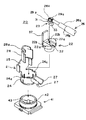
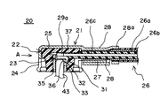
本発明の一つの実施の形態に係る同軸コネクタは、図1にその分解斜視図を、図2にその断面図を、図3に図2のA方向から見た断面図をそれぞれ示す。同軸コネクタ20は、ハウジング21と、該ハウジング21内に装着されるブッシング22と、該ブッシング22に保持されるソケット23とから構成されている。
【0011】
ハウジング21はばね性を有する金属からなり、レセプタクル41の外部導体42に接触する筒状部24、該筒状部24の上部開口を覆う蓋部25、筒状部24から引き出されて同軸ケーブル26の外導体26aをその両側からそれぞれ覆う断面円弧状の一対のカバー部27、蓋部25から引き出されてカバー部27の上にカシメられてこれらカバー部27の上から同軸ケーブル26を把持するカシメ部28を有している。カシメ部28は、その一部が同軸ケーブル26の外皮26bの上にカシメられる爪部28aとなっている。ハウジング21の筒状部24内には、上部開口からブッシング22が挿入されて固定されている。
【0012】
ブッシング22は絶縁性を有する樹脂からなり、図4(B)及び(C)に示すように、ハウジング21の筒状部24への挿入方向先端側(下部側)の外径が上部側の外径よりも小さく、テーパ状となっている。ブッシング22の上部には、図4(A)に示すように、径方向に突出した二つの突片22aが対向して設けられている。これら二つの突片22aは、筒状部24の上部開口側に形成された切欠き部24aに嵌合する。これにより、ブッシング22はハウジング21に
対して位置決めされる。
【0013】
さらに、ブッシング22は、後述するソケット23の支持部31が嵌合する四角形状の嵌合凹部32と、該嵌合凹部32からブッシング22の中心軸の方向に貫通し、ソケット23のばね接触部33を収容するばね接触部収容孔35とを有している。嵌合凹部32の横断面寸法は、ばね接触部収容孔35の横断面寸法よりも大きく、嵌合凹部32とばね接触部収容孔35との間には段部36(図4(B)及び(C)参照)が形成されている。嵌合凹部32の内側壁はテーパ状に形成されており、嵌合凹部32の横断面寸法が段部36に向かって漸減している(図4(C)参照)。ブッシング22の上部には、ソケット23の支持部31を段部36に向かって押圧する押圧部材37が一体に設けられている。
【0014】
ソケット23はばね性を有する金属からなり、図5(A)〜(C)に示すように、接続部29と、ばね接触部33と、支持部31とを有している。ばね接触部33は、一定幅を有する板ばねをリング状に湾曲させた形状を有している。ばね接触部33には、レセプタクル41の中心導体43が圧入され、中心導体43の外周面にばね接触部33の内周面が圧接する。ばね接触部33の上方に配置されている支持部31は、ブッシング22の嵌合凹部32の寸法にほぼ等しい寸法を有する横断面略四角形状を有しており、その一つの辺にばね接触部33が結合している。支持部31は、ばね接触部33を貫通したレセプタクル41の中心導体43の圧入側の先端部分をその内側に収容することができる(図2及び図3参照)。支持部31の上方に配置している接続部29は、支持部31から引き出され、二枚の舌片29aを有している。これら舌片29aの間に同軸ケーブル26の中心導体26cの先端部が挿入され、二枚の舌片29aによってカシメられる。これにより、ソケット23が同軸ケーブル26の中心導体26cに電気的に接続される。
【0015】
同軸ケーブル26が接続されたソケット23は、図2及び図3に示すように、支持部31がブッシング22の嵌合凹部32に嵌合すると共に、ばね接触部33がばね接触部収容孔35(図4参照)内に収容される。そして、ブッシング22と一体に形成された押圧部材37を折り曲げ、嵌合凹部32の開口部を塞ぐ。この状態で、ブッシング22をハウジング21の筒状部24内に収容した後、ハウジング21の蓋部25を折り曲げ、ブッシング22の上面に被せる。次に、ハウジング21のカシメ部28を一対のカバー部27の上にカシメ付けてこれらカバー部27の上から同軸ケーブル26を把持する。さらに、爪部28aを同軸ケーブル26の外皮26bの上にカシメる。
【0016】
こうして得られた同軸コネクタ20は、ハウジング21の蓋部25とソケット23との間に配設された押圧部材37が、ソケット23の支持部31をブッシング22の段部36に向かって押圧するので、段部36に支持部31が係止される。従って、ソケット23がブッシング22から抜けるのが防止される。従って、図6及び図7に示した従来の同軸ケーブル15が備えていた抜け防止のためのブリッジ部12を省略することができる。この結果、同軸コネクタ20の低背化を図ることができる。
【0017】
さらに、この同軸コネクタ20が、レセプタクル41に結合されると、レセプタクル41の内部導体43がソケット23のばね接触部33を貫通し、その圧入側の先端部分が支持部31内に達するまで挿入される。これにより、ソケット23の支持部31内にレセプタクル41の内部導体43が受け入れられる分、同軸コネクタ20の高さをより低くすることができる。しかも、レセプタクル41の内部導体43とソケット23のばね接触部33との結合ストロークが大きくなり、レセプタクル41の外部導体42と筒状部24との結合ストロークも大きくなり、レセプタクル41との結合の機械的及び電気的な安定性を確保することができる。
【0018】
また、ソケット23の支持部31が四角形状を有しているので、その外周面がブッシング22の嵌合凹部32の内壁側面に当接し易くなり、嵌合凹部32内での支持部31のがたつきを防止することができる。例えば、同軸コネクタ20をレセプタクル41へ着脱する際に、ソケット23のばね接触部33に回転力が加わっても、支持部31が回転することがなく、ソケット23に接続されている同軸ケーブル26の中心導体26cが切断することもない。
【0019】
さらに、ブッシング22の嵌合凹部32の横断面寸法が段部36に向かって漸減しているので、嵌合凹部32のテーパ状の内壁面により、ソケット23をブッシング22に容易に挿入させることができる。
【0020】
本発明は、前記実施形態に限定されるものではなく、その要旨の範囲内で種々に変更することができる。例えば、ソケット23の支持部31は、横断面が三角形、五角形等の多角形や、円形であってもよい。また、押圧部材37はブッシング22と別体のものであってもよい。
【0021】
【発明の効果】
以上の説明からも明らかなように、本発明によれば、押圧部材によって、ソケットの支持部がブッシングの嵌合凹部とばね接触部収容孔との間に形成された段部に堅固に係止されるため、ソケットがブッシュから抜ける心配はない。従って、従来の抜け防止のためのブリッジ部をブッシングに設ける必要がなく、ブリッジ部の寸法分を結合ストロークとして利用でき、同軸コネクタの背を低くすることができる。
【0022】
また、ソケットの支持部の横断面形状を多角形及び円形のうちの一つに設定することにより、ソケットの外周面がブッシングの嵌合凹部の内壁側面に当接し易くなり、嵌合凹部内でのソケットの支持部のがたつきを防止することができる。さらに、ブッシングの嵌合凹部の横断面寸法を段部に向かって漸減させることにより、ソケットをブッシングに容易に挿入させることができる。
【図面の簡単な説明】
【図1】本発明に係る同軸コネクタの一つの実施形態の分解斜視図。
【図2】図1に示した同軸コネクタの断面図。
【図3】図2の矢印A方向から見た同軸コネクタの断面図。
【図4】図1に示した同軸コネクタのブッシングを示すものであり、(A)は平面図、(B)は(A)のX−X断面図、(C)は(A)のY−Y断面図。
【図5】図1に示した同軸コネクタのソケットを示すものであり、(A)は平面図、(B)は正面図、(C)は底面図。
【図6】従来の同軸コネクタの一例を示す断面図。
【図7】図6の矢印A方向から見た同軸コネクタの断面図。
【符号の説明】
21…ハウジング
22…ブッシング
23…ソケット
24…筒状部
25…蓋部
31…支持部
32…嵌合凹部
33…ばね接触部
35…ばね接触部収容孔
36…段部
37…押圧部材[0001]
BACKGROUND OF THE INVENTION
The present invention relates to a coaxial connector used for connecting a coaxial cable, and more particularly to a coaxial connector used as a component of a portable communication device.
[0002]
[Prior art]
An example of this type of conventional coaxial connector is shown in FIGS. The
[0003]
The
[0004]
[Problems to be solved by the invention]
By the way, in recent years, communication devices that are very small and thin are becoming popular. Along with this, electronic components used in these devices are also small and short, and even a coaxial connector is required to be small and short. However, the conventional
[0005]
SUMMARY OF THE INVENTION An object of the present invention is to provide a coaxial connector that can obtain a mechanically and electrically stable connection and that is short.
[0006]
[Means and Actions for Solving the Problems]
In order to achieve the above object, a coaxial connector according to the present invention comprises:
(A) a housing that has a cylindrical portion that contacts the outer conductor of the receptacle and a lid that covers the upper opening of the cylindrical portion, and that is electrically connected to the outer conductor of the coaxial cable;
(B) a substantially ring-shaped spring contact portion that is in pressure contact with the outer peripheral surface of the center conductor of the receptacle, and a spring cross section that is larger than the cross section of the spring contact portion so that the center conductor of the receptacle penetrates, and the spring contact A substantially ring-shaped support portion that supports the portion, and a socket that is electrically connected to the central conductor of the coaxial cable;
(C) A fitting recess in which the support portion of the socket is fitted, and a spring that accommodates the spring contact portion of the socket, having a cross section that is in communication with the fitting recess and is smaller than the cross section of the fitting recess. A bushing having a contact portion receiving hole and mounted in the cylindrical portion of the housing;
(D) A pressure disposed between the lid portion of the housing and the socket, and pressing the support portion of the socket against a step formed between the fitting recess of the bushing and the spring contact portion receiving hole. Members,
It is provided with.
[0007]
With the above configuration, the support member of the socket is firmly locked to the step formed between the fitting recess of the bushing and the spring contact portion accommodation hole by the pressing member, so there is no concern that the socket will come out of the bushing. Absent. Therefore, it is not necessary to provide a conventional bridge portion for preventing the disconnection in the bushing, and the size of the bridge portion is used as a coupling stroke, so that the coaxial connector is lowered.
[0008]
In addition, by setting the cross-sectional shape of the support part of the socket to one of a polygon and a circle, the outer peripheral surface of the support part of the socket can be easily brought into contact with the inner wall side surface of the fitting recess of the bushing. Shaking of the support portion of the socket in the recess is prevented. Furthermore, by gradually reducing the cross-sectional dimension of the fitting recess of the bushing toward the stepped portion, the socket can be easily inserted into the bushing.
[0009]
DETAILED DESCRIPTION OF THE INVENTION
DESCRIPTION OF EMBODIMENTS Hereinafter, embodiments of a coaxial connector according to the present invention will be described in detail with reference to the accompanying drawings.
[0010]
1 is an exploded perspective view, FIG. 2 is a cross-sectional view thereof, and FIG. 3 is a cross-sectional view as viewed from the direction A in FIG. The
[0011]
The
[0012]
The
[0013]
Further, the
[0014]
The
[0015]
As shown in FIGS. 2 and 3, the
[0016]
In the
[0017]
Further, when the
[0018]
Further, since the
[0019]
Furthermore, since the cross-sectional dimension of the
[0020]
The present invention is not limited to the above embodiment, and can be variously modified within the scope of the gist. For example, the
[0021]
【The invention's effect】
As is clear from the above description, according to the present invention, the supporting member of the socket is firmly locked to the step formed between the fitting recess of the bushing and the spring contact portion receiving hole by the pressing member. Therefore, there is no worry that the socket will come out of the bush. Therefore, it is not necessary to provide a conventional bridge portion for preventing the disconnection in the bushing, and the dimension of the bridge portion can be used as a coupling stroke, and the height of the coaxial connector can be lowered.
[0022]
Moreover, by setting the cross-sectional shape of the support portion of the socket to one of a polygon and a circle, the outer peripheral surface of the socket can easily come into contact with the inner wall side surface of the fitting recess of the bushing, It is possible to prevent rattling of the support portion of the socket. Furthermore, the socket can be easily inserted into the bushing by gradually decreasing the cross-sectional dimension of the fitting recess of the bushing toward the stepped portion.
[Brief description of the drawings]
FIG. 1 is an exploded perspective view of one embodiment of a coaxial connector according to the present invention.
FIG. 2 is a cross-sectional view of the coaxial connector shown in FIG.
3 is a cross-sectional view of the coaxial connector as viewed from the direction of arrow A in FIG.
4A and 4B show bushings of the coaxial connector shown in FIG. 1, wherein FIG. 4A is a plan view, FIG. 4B is a sectional view taken along line XX of FIG. 1A, and FIG. Y sectional drawing.
5 shows a socket of the coaxial connector shown in FIG. 1, wherein (A) is a plan view, (B) is a front view, and (C) is a bottom view. FIG.
FIG. 6 is a cross-sectional view showing an example of a conventional coaxial connector.
7 is a cross-sectional view of the coaxial connector as seen from the direction of arrow A in FIG.
[Explanation of symbols]
DESCRIPTION OF
Claims (3)
前記レセプタクルの中心導体の外周面に圧接する略リング状ばね接触部と、前記レセプタクルの中心導体が貫通するように前記ばね接触部の横断面より大きい横断面を有しかつ前記ばね接触部を支持する略リング状支持部とを有し、前記同軸ケーブルの中心導体に電気的に接続するソケットと、
前記ソケットの支持部が嵌合する嵌合凹部と、該嵌合凹部に連通しかつ前記嵌合凹部の横断面より小さい横断面を有した、前記ソケットのばね接触部を収容するばね接触部収容孔とを有し、前記ハウジングの筒状部内に装着されるブッシングと、
前記ハウジングの蓋部と前記ソケットとの間に配設され、前記ソケットの支持部を前記ブッシングの嵌合凹部とばね接触部収容孔との間に形成された段部に押圧する押圧部材と、
を備えたことを特徴とする同軸コネクタ。A housing that contacts the outer conductor of the receptacle and a lid that covers the upper opening of the tubular portion, and that is electrically connected to the outer conductor of the coaxial cable;
A substantially ring-shaped spring contact portion that presses against the outer peripheral surface of the center conductor of the receptacle, and a cross section that is larger than the cross section of the spring contact portion so that the center conductor of the receptacle penetrates and supports the spring contact portion A substantially ring-shaped support portion, and a socket electrically connected to a central conductor of the coaxial cable;
A fitting recess into which the support portion of the socket is fitted, and a spring contact portion accommodating the spring contact portion of the socket having a cross section communicating with the fitting recess and smaller than the cross section of the fitting recess. A bushing having a hole and mounted in the cylindrical portion of the housing;
A pressing member disposed between the lid portion of the housing and the socket, and pressing the support portion of the socket against a step formed between the fitting recess of the bushing and the spring contact portion receiving hole;
A coaxial connector characterized by comprising:
Priority Applications (1)
| Application Number | Priority Date | Filing Date | Title |
|---|---|---|---|
| JP11217398A JP3783399B2 (en) | 1998-04-22 | 1998-04-22 | Coaxial connector |
Applications Claiming Priority (1)
| Application Number | Priority Date | Filing Date | Title |
|---|---|---|---|
| JP11217398A JP3783399B2 (en) | 1998-04-22 | 1998-04-22 | Coaxial connector |
Publications (2)
| Publication Number | Publication Date |
|---|---|
| JPH11307189A JPH11307189A (en) | 1999-11-05 |
| JP3783399B2 true JP3783399B2 (en) | 2006-06-07 |
Family
ID=14580089
Family Applications (1)
| Application Number | Title | Priority Date | Filing Date |
|---|---|---|---|
| JP11217398A Expired - Lifetime JP3783399B2 (en) | 1998-04-22 | 1998-04-22 | Coaxial connector |
Country Status (1)
| Country | Link |
|---|---|
| JP (1) | JP3783399B2 (en) |
Families Citing this family (2)
| Publication number | Priority date | Publication date | Assignee | Title |
|---|---|---|---|---|
| JP4495451B2 (en) * | 2003-12-25 | 2010-07-07 | 株式会社アイペックス | Connector for coaxial cable |
| JP4139782B2 (en) | 2004-01-20 | 2008-08-27 | ホシデン株式会社 | Connector for coaxial cable |
Family Cites Families (6)
| Publication number | Priority date | Publication date | Assignee | Title |
|---|---|---|---|---|
| JPS60172281U (en) * | 1984-04-24 | 1985-11-14 | 星電器製造株式会社 | coaxial plug |
| JPH089897Y2 (en) * | 1990-02-28 | 1996-03-21 | 株式会社村田製作所 | Coaxial connector |
| JPH088547Y2 (en) * | 1992-01-21 | 1996-03-06 | エスエムケイ株式会社 | Coaxial cable connector |
| JP3585177B2 (en) * | 1992-02-03 | 2004-11-04 | 株式会社村田製作所 | L-type coaxial connector |
| JPH05347169A (en) * | 1992-06-12 | 1993-12-27 | Murata Mfg Co Ltd | Coaxial connector |
| JP3134081B2 (en) * | 1996-06-03 | 2001-02-13 | エスエムケイ株式会社 | Micro coaxial connector |
-
1998
- 1998-04-22 JP JP11217398A patent/JP3783399B2/en not_active Expired - Lifetime
Also Published As
| Publication number | Publication date |
|---|---|
| JPH11307189A (en) | 1999-11-05 |
Similar Documents
| Publication | Publication Date | Title |
|---|---|---|
| JP3364837B2 (en) | Electrical connector having integral latch and strain relief device | |
| US7758377B2 (en) | Coaxial connector | |
| JP4761320B2 (en) | connector | |
| JPH11260463A (en) | Electric connector assembly | |
| JPS6318840B2 (en) | ||
| JP2012113983A (en) | Connector and connector unit | |
| US7540774B1 (en) | Coaxial connector | |
| TWI434472B (en) | Coaxial connector | |
| US8215985B2 (en) | Step up pin for coax cable connector | |
| US6447335B1 (en) | Cable end connector | |
| JPH11307158A (en) | Coaxial connector | |
| JP3783399B2 (en) | Coaxial connector | |
| CN210326253U (en) | Pin terminal | |
| US6142795A (en) | Electrical connector with grounded contact | |
| JP3884254B2 (en) | Coaxial connector | |
| US6174183B1 (en) | Coaxial cable connector with normally closed switch | |
| JP2001307842A (en) | Coaxial connector and electronic equipment equipped with this coaxial connector | |
| JP3013171B1 (en) | Coaxial connector | |
| CN110416840A (en) | A kind of curved formula Minisize coaxial connector | |
| JPH0625903Y2 (en) | Coaxial connector | |
| JP2683707B2 (en) | Coaxial cable connector | |
| JPH08153557A (en) | Female terminal and coaxial connector using it | |
| JP3931398B2 (en) | Electrical connector | |
| JP3074450B2 (en) | Coaxial connector | |
| JP3494903B2 (en) | Wire connection structure to insulation displacement terminal |
Legal Events
| Date | Code | Title | Description |
|---|---|---|---|
| A621 | Written request for application examination |
Free format text: JAPANESE INTERMEDIATE CODE: A621 Effective date: 20040401 |
|
| A977 | Report on retrieval |
Free format text: JAPANESE INTERMEDIATE CODE: A971007 Effective date: 20050824 |
|
| A131 | Notification of reasons for refusal |
Free format text: JAPANESE INTERMEDIATE CODE: A131 Effective date: 20050913 |
|
| A521 | Written amendment |
Free format text: JAPANESE INTERMEDIATE CODE: A523 Effective date: 20051109 |
|
| TRDD | Decision of grant or rejection written | ||
| A01 | Written decision to grant a patent or to grant a registration (utility model) |
Free format text: JAPANESE INTERMEDIATE CODE: A01 Effective date: 20060221 |
|
| A61 | First payment of annual fees (during grant procedure) |
Free format text: JAPANESE INTERMEDIATE CODE: A61 Effective date: 20060306 |
|
| R150 | Certificate of patent or registration of utility model |
Free format text: JAPANESE INTERMEDIATE CODE: R150 |
|
| FPAY | Renewal fee payment (event date is renewal date of database) |
Free format text: PAYMENT UNTIL: 20090324 Year of fee payment: 3 |
|
| FPAY | Renewal fee payment (event date is renewal date of database) |
Free format text: PAYMENT UNTIL: 20100324 Year of fee payment: 4 |
|
| FPAY | Renewal fee payment (event date is renewal date of database) |
Free format text: PAYMENT UNTIL: 20110324 Year of fee payment: 5 |
|
| FPAY | Renewal fee payment (event date is renewal date of database) |
Free format text: PAYMENT UNTIL: 20110324 Year of fee payment: 5 |
|
| FPAY | Renewal fee payment (event date is renewal date of database) |
Free format text: PAYMENT UNTIL: 20120324 Year of fee payment: 6 |
|
| FPAY | Renewal fee payment (event date is renewal date of database) |
Free format text: PAYMENT UNTIL: 20120324 Year of fee payment: 6 |
|
| FPAY | Renewal fee payment (event date is renewal date of database) |
Free format text: PAYMENT UNTIL: 20130324 Year of fee payment: 7 |
|
| FPAY | Renewal fee payment (event date is renewal date of database) |
Free format text: PAYMENT UNTIL: 20130324 Year of fee payment: 7 |
|
| FPAY | Renewal fee payment (event date is renewal date of database) |
Free format text: PAYMENT UNTIL: 20140324 Year of fee payment: 8 |
|
| EXPY | Cancellation because of completion of term |