JP3782555B2 - Bonding jig for vertical plate to horizontal plate and bonding method for vertical plate to horizontal plate using the same jig - Google Patents
Bonding jig for vertical plate to horizontal plate and bonding method for vertical plate to horizontal plate using the same jig Download PDFInfo
- Publication number
- JP3782555B2 JP3782555B2 JP23863897A JP23863897A JP3782555B2 JP 3782555 B2 JP3782555 B2 JP 3782555B2 JP 23863897 A JP23863897 A JP 23863897A JP 23863897 A JP23863897 A JP 23863897A JP 3782555 B2 JP3782555 B2 JP 3782555B2
- Authority
- JP
- Japan
- Prior art keywords
- plate
- pressing
- horizontal
- members
- vertical
- Prior art date
- Legal status (The legal status is an assumption and is not a legal conclusion. Google has not performed a legal analysis and makes no representation as to the accuracy of the status listed.)
- Expired - Fee Related
Links
Images


Classifications
-
- B—PERFORMING OPERATIONS; TRANSPORTING
- B27—WORKING OR PRESERVING WOOD OR SIMILAR MATERIAL; NAILING OR STAPLING MACHINES IN GENERAL
- B27M—WORKING OF WOOD NOT PROVIDED FOR IN SUBCLASSES B27B - B27L; MANUFACTURE OF SPECIFIC WOODEN ARTICLES
- B27M3/00—Manufacture or reconditioning of specific semi-finished or finished articles
- B27M3/0013—Manufacture or reconditioning of specific semi-finished or finished articles of composite or compound articles
- B27M3/0026—Manufacture or reconditioning of specific semi-finished or finished articles of composite or compound articles characterised by oblong elements connected laterally
- B27M3/0053—Manufacture or reconditioning of specific semi-finished or finished articles of composite or compound articles characterised by oblong elements connected laterally using glue
-
- B—PERFORMING OPERATIONS; TRANSPORTING
- B27—WORKING OR PRESERVING WOOD OR SIMILAR MATERIAL; NAILING OR STAPLING MACHINES IN GENERAL
- B27M—WORKING OF WOOD NOT PROVIDED FOR IN SUBCLASSES B27B - B27L; MANUFACTURE OF SPECIFIC WOODEN ARTICLES
- B27M3/00—Manufacture or reconditioning of specific semi-finished or finished articles
- B27M3/0013—Manufacture or reconditioning of specific semi-finished or finished articles of composite or compound articles
Description
【0001】
【発明が属する技術分野】
本発明は、水平板材の端縁に沿って垂直板材を圧着するための圧着治具と、同治具を用いた水平板材に対する垂直板材の接着方法とに関し、例えば、人造大理石製のシステムキッチンカウンターや洗面カウンターを製造するにあたって、長尺な水平板材からなるカウンター板材に、長尺板材からなる前垂れ板材や背立て板材を垂直方向に接着する際に使用される圧着治具、並びに同治具を用いたカウンター板材に対する前垂れ板材や背立て板材の接着方法に関する。
【0002】
【従来の技術】
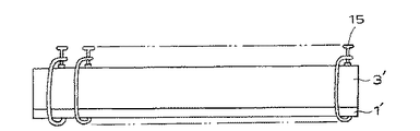
近年、一般家庭、飲食店、ホテルなどにおいて、各種のカウンターに人造大理石が多用されるようになってきている。人造大理石製のキッチンカウンターや洗面カウンターなどの前垂れや背立ては、シート状の原板から前垂れ板材や背立て板材を別途に切り出しカウンター板材に接着して形成されている。従来の接着方法は図4〜図7に示すように、カウンター板材1′の全長にわたって前垂れ板材2′や背立て板材3′をほぼ均一な力で圧着できるように、接着面に接着剤を流して位置決め接合させた後、その全長にわたって手作業でクランプやハタガネなどの固定具15を約10cm間隔で締め付けて固定している。
【0003】
【発明が解決しようとする課題】
しかしながら、上述のようにクランプやハタガネで固定する方法では、クランプやハタガネを締めつける際に板材同士がずれ易く、所定の角度及び位置で接着するには作業者の熟練が必要となる。また手作業によるため、たとえ熟練者であっても常に一定の仕上がりとすることは不可能である。更には、数多くのクランプやハタガネを必要とし、その着脱にも多大の時間を費やすことが多い。
【0004】
そこで本発明は、従来、手作業でクランプやハタガネを締めつけて固定していた圧着作業を作業者の熟練を必要とせず、かつ短時間で前垂れ板材や背立て板材とカウンター板材との圧着を可能とする圧着治具と、同治具を使用して常に一定の状態で美麗に仕上げることのできる接着方法とを提供することを目的としている。
【0005】
【課題を解決するための手段】
上記課題を解決するために、本発明は、長尺の水平板材と同じく長尺の2枚の垂直板材との間の水平方向の位置決め手段を有する作業台又はその周辺部材にセットされ、前記水平板材の両長手端縁において前記水平板材と前記垂直板材との長手端縁同士をそれぞれ長手端縁に沿って直交して圧着固定するための圧着治具であって、前記作業台上に載置された水平板材に対して垂直板材を前記水平板材の長手端縁に沿って直交して圧着するための複数の押圧部材と、その圧着面に沿って複数配された前記押圧部材を押圧方向に作動させる作動手段と、同作動手段の起動・停止手段とを備えてなり、一方の前記垂直板材は前記押圧部材により前記位置決め手段に向けて押圧され、同押圧部材を作動する前記作動手段が、水平方向に4本/m以上の間隔で配され、他方の前記垂直板材は位置決め手段に向けて押圧する押圧部材と前記作業台表面に向けて押圧する押圧部材のそれぞれにより水平方向及び垂直方向とに押圧され、前記位置決め手段に向けて押圧する押圧部材を作動する作動手段が、水平方向に3本/m以上の間隔で配され、前記作業台に向けて押圧する押圧部材を作動する作動手段が、垂直方向に4本/m以上の間隔で配されてなることを特徴とする水平板材に対する垂直板材の圧着治具を主要な構成としている。
【0006】
前記作動手段として流体圧シリンダを採用することができ、或いは、前記作動手段にシリンダ型空気ばね又は磁石ばねを使用することもできる。
【0007】
前記作動手段は前記板材の長さ方向に複数配されてなることが好ましい。更にその場合には、前記押圧部材は複数からなり、各押圧部材は複数の前記作動手段のそれぞれに取り付けられている。或いは、前記押圧部材は複数からなり、各押圧部材は複数の前記作動手段のうちの幾つかに連結して取り付けられていてもよい。
【0008】
また、複数の前記作動手段のうち、長さ方向中央に配された前記作動手段を最初に作動させ、次いで、その両側に配された前記作動手段を順次その両端側に向けて作動する作動制御手段を備えてなることが好ましい。
【0009】
更に、本発明は、長尺の水平板材の前後端縁に沿って、同じく長尺の2枚の垂直板材を長さ方向の端縁を直交させて圧着により接着する接着方法であって、上述の圧着治具を使用して接着することを特徴とする接着方法をも他の主要な構成としている。
【0010】
前記板材が人造大理石からなり、前記垂直板材はカウンター用背立て板材及び/又は前垂れ板材である場合に、前記前垂れを水平方向に6Kg/cm2以上の力で、前記背立てを水平方向に1Kg/cm2以上の力と垂直方向に7Kg/cm2以上の力とで、それぞれ独立的に押圧することが好ましい。
【0011】
更に、前記前垂れ板材を4本/m以上の間隔で配された前記作動手段の作動により水平方向に押圧し、前記背立て板材を3本/m以上の間隔で配された前記作動手段の作動により水平方向に押圧すると共に、4本/m以上の間隔で配された前記作動手段の作動により垂直方向に押圧することが好ましい。
【0012】
例えばキッチンカウンターのカウンター板材に、上記前垂れ板材及び背立て板材を接着してキッチンカウンターを組み付ける際には、先ず作業台及びその周辺に上述の圧着治具をセットすると共に前記カウンター板材を作業台に載置し、同カウンター板材に前記前垂れ板材及び背立て板材を各板材の接着面に接着材を塗布した状態で載置する。その後、本発明の圧着治具の作動部材を作動させ、押圧部材により前記カウンター板材に対して前記前垂れ板材及び背立て板材を押圧する。このとき、前記作動部材の作動により各板材が前記作業台の位置決め手段に押しつけられて所定の位置に確実に位置決め保持されるため、板材同士が互いにズレることがない。しかも手作業の場合のように押圧力にバラツキがなく長手方向に沿って一定の押圧力で圧着されるため、常に一定した形態に美麗に仕上がり、また、多数の固定具を固定することもないため作業時間が大幅に短縮され、作業効率の向上を図ることができる。
【0013】
【発明の実施の形態】
以下、本発明の実施の形態について、図示実施例を参照して詳細に説明する。図1は、本発明の接着方法による接着手順を概略的に示す説明図であり、図2及び図3は本発明の圧着治具の一部を含む部分説明図である。
【0014】
本実施例では、システムキッチンの人造大理石を使ったキッチンカウンターの製作を例示するが、本発明は他の材質、例えば木材、天然大理石、一般の合成樹脂板材などの組付けにも適用される。
【0015】
符号1はシステムキッチンのキッチンカウンター用のカウンター板材であり、符号2は同カウンター用の前垂れ板材、符号3及び4は同カウンター用の第1及び第2背立て板材である。これらの板材は全て人造大理石(登録商標:デュポンコーリアン・カメオホワイト)からなり、前記前垂れ板材2と第1及び第2背立て板材3,4とは、長さ2750mm、幅760mm、厚み13mmのシートからそれぞれ所定の寸法に切り出されたものである。第1背立て板材3は長尺の角材からなり、第2背立て板材4は同長の板材からなる。
【0016】
前記カウンター板材1の前端1aには、同前端縁1aの端面を前記前垂れ板材2の裏面上端縁に沿って当接させ、前記前垂れ板材2を下方に向けて直角に接着する。一方、前記カウンター板材1の後端1bには、同カウンター板材1の上角部が前記第1背立て板材3の前後幅寸法よりも0〜2mm小さな幅寸法で浅く切り欠かれて段部1cに形成されており、前記段部1cには前記第1背立て板材3がその下端を係合させた状態で垂直に接着される。更に、第2背立て板材4の裏面が前記第1背立て板材3の後端面と面合わせされた状態で、第1背立て板材3の上面に上方から接着され、システムキッチンのキッチンカウンターが組み付けられる。
【0017】
この組み付けに使用される本発明の圧着治具は、前記カウンター板材1に対する前記前垂れ板材2及び第1及び第2背立て板材3,4の位置決め手段を有する作業台10又はその周辺にセットされる。前記圧着治具は前記前垂れ板材2及び第1及び第2背立て板材3,4の長さに略等しい長さをもつフレームを有し、そのフレームには前記前垂れ板材2及び第1及び第2背立て板材3,4をカウンター板材1の長さ方向に沿って圧着するためにそれぞれに配された複数の押圧部材が保持されている。更に、前記押圧部材を作動する複数の作動手段と、同作動手段の起動・停止手段とを備え、複数の前記作動手段のうち、長さ方向中央に配された前記作動手段を最初に作動させ、次いで、その両側に配された前記作動手段を順次その両端側に向けて作動する作動制御手段を更に備えている。
【0018】
前記カウンター板材1に前記前垂れ板材2と第1及び第2背立て板材3,4を接着するには、まず、本発明の前記圧着治具を作業台10及びその周辺にセットすると共に、前記作業台10に前記カウンター板材1を載置する。このとき、前記作業台10の上面には、前記前垂れ板材2の上下寸法からカウンター板材1の厚み寸法を引いた高さ寸法になるように、複数の支持台11を重ねて載置して高さを調節する。前記作業台10はその端縁部に同作業台10の上面と垂直に延設された本発明の位置決め手段である縦壁部10aを備えている。前記支持台11の上面にカウンター板材1を、その後端1bが前記縦壁部10aに対向する方向で載置する。その後、前記前垂れ板材2を図5のようにその上端縁を前記カウンター板材1の前端1aから離れる方向に傾斜させて立たせる。このとき、前記カウンター板材1の前端1aの端面と前記前垂れ板材2の裏面との間にはV字状の間隙Aが形成される。この間隙Aの部分に人造大理石用の瞬間接着剤アロンアルファ(東亜合成製)を、前記カウンター板材1及び前垂れ板材2の全長にわたって塗布する。
【0019】
一方、第1背立て板材3はその下端面に、第2背立て板材4は下端面にそれぞれ全長にわたって前記接着剤を塗布して、前記第1背立て板材3を前記カウンター板材1の段部1aに載置し、更に前記第2背立て板材4を前記第1背立て板材3の後端上縁に沿って載置する。その状態で、圧着治具の起動手段であるレバーを操作して本発明の作動手段である第1〜第3エアシリンダ5〜7を作動させる。
【0020】
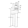
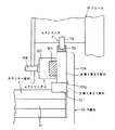
前記第1エアシリンダ5は前記前垂れ板材2の長さ方向に沿って複数本(本実施例では11本)配されており、同前垂れ板材2の前面を後方に向けて図1のX1方向に押圧する。前記第2エアシリンダ6も前記背立て板材3,4の長さ方向に沿って複数本(本実施例では6本)設けられ、前記第2背立て板材3の前面を後方に向けてX2方向に押圧すると共に、前記第3エアシリンダ7も前記背立て板材3,4の長さ方向に沿って複数本(本実施例では11本)配されて、前記第2背立て板材3の上端縁を下方に向けてY方向に押圧する。
【0021】
11本の第1エアシリンダ5は中央の1本の第1エアシリンダ5が独立し、更に他の第1エアシリンダ5は2本1組となって、それぞれ中央の第1エアシリンダ5と5組の第1エアシリンダ5のそれぞれのピストンロッド5aの先端に、本発明の押圧部材である計6個の押えブロック5cがそれぞれ取り付けられている。6本の第2エアシリンダ6は2本1組となって、そのピストンロッド6aの先端に、計3個の押えブロック6cがそれぞれ取り付けられている。前記押えブロック5c,6cは断面コ字状をなしており、更に、前記押えブロック5c,6cの端面にはゴムパッド5b,6bが装着されており、そのため前記板材1〜4に前記ブロック5c,6cが当接した際にそれらの板材1〜4を傷つけることがない。また、11本の第3エアシリンダ7は中央部及びその隣り合う部分に分けられ、その分けられた中央部の複数の第3エアシリンダ7群と、隣り合う部分の複数の各第3エアシリンダ7群ごとの各ピストンロッド7aの端面に、それぞれ押圧部材としての3本のゴムパッド7bが装着されている。
【0022】
複数の前記第1エアシリンダ5は断面コ字状をなすフレーム8に、そのピストンロッド5aを挿通させて固着されており、前記ピストンロッド5aの伸縮にともない、前記押えブロック5c及びゴムパッド5bが前記フレーム8の内部を摺動し、同フレーム8の開口部分から挿脱される。一方、第2及び第3エアシリンダ7,8は互いに直交する方向に作動されるよう、フレーム9に固着されている。
【0023】
なお、本実施例では前記押圧部材が複数の作動手段を連結して取り付けられているが、1の作動手段に対して1の押圧部材を取り付けることもでき、更には複数の作動手段の全てを単一の長尺な押圧部材で連結して取り付けることもできる。
【0024】
本実施例では前記前垂れ板材2及び背立て板材3,4をカウンター板材1に押しつける際に、前記作動手段としてエアシリンダ5〜7を利用しているが、この他にも油圧シリンダを使用することができ、また、前記作動手段としてシリンダ型空気ばね又は磁石ばねを使用することもできる。
【0025】
本実施例では、前記第1エアシリンダ5のエアー圧を6kg/cm2に、第2エアシリンダ6のエアー圧を1kg/cm2に、更に前記第3エアシリンダ7のエアー圧を7kg/cm2に設定した。このように、本実施例の圧着治具を用いれば、押圧部材の押圧力を任意の値に設定し、長尺な板材の全長にわたって均一に押圧することが可能となる。
【0026】
先ず、起動手段により前記第1エアシリンダ5を作動して、前記前垂れ板材2を後方へ押圧すると、前記カウンター板材1が後方へ移動して縦壁部10aに押しつけられて確実に位置決めされ、前記縦壁部10aとの間で前記カウンター板材1と前垂れ板材2とが互いに強力に圧着される。
【0027】
更に、上述したように前記第1背立て板材3が係合載置されている前記カウンター板材1に形成された段部1cは、その前後幅寸法が前記第1背立て板材3の前後幅寸法よりも0〜2mm程度小さいため、前記第1背立て板材3の後端縁が前記カウンター板材1の後端縁からわずかに突出することになる。そのため、前記カウンター板材1の後方への移動に伴い、同カウンター板材1の段部1cに係合載置されている第1背立て板材3が前記縦壁部10aに当接して強力に押圧され、前記段部1cに圧着される。
【0028】
また、前記第1エアシリンダ5に次いで作動された第2エアシリンダ−6により前記第2背立て板材4が前記縦壁部10aに向けて押しつけられ、前記第1背立て板材3の後端面と前記第2背立て板材4の後面とが面一になるよう確実に位置決めされる。その状態で、前記第2エアシリンダ6とほぼ同時に作動された前記第3エアシリンダ7により、前記第2背立て板材4が下方へ向けて押圧され、前記第1及び第2背立て板材3,4が前記カウンター板材1に圧着される。
【0029】
なお、本実施例では図3に示すように、前記縦壁部10aの前面には、前記カウンター板材1及び第1背立て板材3の接着面と、前記第1背立て板材3及び第2背立て板材4の接着面とに相当する高さ位置に、凹溝部10bが形成されており、前記接着面から流出した過剰の接着剤を収容することができる。
【0030】
また、前記カウンター板材1の長手方向に沿って配された複数の前記第1〜第3エアシリンダ5〜7は、図示せぬ前記作動制御手段により前記長手方向の中央に配されたエアシリンダ群が最初に作動され、次いで、その両側に配されたエアシリンダ群が順次その両端側に向けて作動されて、最後に両端に配されたエアシリンダ群が作動される。
【0031】
以上に説明した本発明の圧着治具を用いて、本発明の接着方法により接着する場合に、前記カウンター板材1、前垂れ板材2、及び背立て板材3,4に接着剤を塗布し、互いに圧着させて接着するまでの作業が2分で完了した。これに対して従来のような手作業によりハンドクランプを使用した方法で圧着した場合には7分30秒を要し、本発明の圧着治具及び接着方法を採用することにより、作業時間が大幅に短縮され、作業効率が向上した。
【0032】
【発明の効果】
以上、説明したように、本発明の圧着治具を利用することにより、作業時間が約1/4と大幅に短縮され、作業効率の向上を図ることができる。また、その仕上がりについてみても、板材同士の位置決めが確実になされるため、ズレが生じることもなく、しかも、手作業の場合のように押圧力にバラツキがなく長手方向に沿って一定の押圧力で圧着されるため、常に一定した形態に美麗に仕上がる。
【図面の簡単な説明】
【図1】本発明の接着方法による接着作業を示す説明図である。
【図2】本発明の圧着装置を含む前垂れ板材の接着作業を示す説明図である。
【図3】本発明の圧着装置を含む背立て板材の接着作業を示す説明図である。
【図4】従来のカウンター板材に背立て板材を接着する作業方法を示す説明図である。
【図5】図4の側面からの図である。
【図6】従来のカウンター板材に前垂れ板材を接着する他の作業方法を示す説明図である。
【図7】図7の側面からの図である。
【符号の説明】
1 カウンター板材
1a 前端
1b 後端
1c 段部
2 前垂れ板材
3 第1背立て板材
4 第2背立て板材
5〜7 第1〜第3エアシリンダ
5a〜7a ピストンロッド
5b〜7b ゴムパッド
5c,6c 押えブロック
8,9 フレーム
10 作業台
10a 縦壁部
10b 凹溝部
11 支持台[0001]
[Technical field to which the invention belongs]
The present invention relates to a crimping jig for crimping a vertical board along the edge of the horizontal board, and a method for bonding the vertical board to the horizontal board using the jig, for example, a system kitchen counter made of artificial marble, In manufacturing a wash counter, a crimping jig used to vertically bond a front hanging board or backboard made of a long board to a counter board made of a long horizontal board, and the same jig were used. The present invention relates to a method for adhering a front plate or a back plate to a counter plate.
[0002]
[Prior art]
In recent years, artificial marble has been frequently used for various counters in ordinary homes, restaurants, hotels and the like. Artificial marble kitchen counters and vanity counters such as front stools and back stands are formed by cutting out front slats and back slabs separately from sheet-like original plates and bonding them to the counter plate materials. As shown in FIGS. 4 to 7, the conventional bonding method is to pour an adhesive on the bonding surface so that the front plate 2 ′ and the
[0003]
[Problems to be solved by the invention]
However, in the method of fixing with a clamp or a strip as described above, the plate materials are easily displaced when the clamp or the strip is tightened, and an operator's skill is required for bonding at a predetermined angle and position. Moreover, since it is based on manual work, even a skilled person cannot always achieve a certain finish. Furthermore, many clamps and strips are required, and a lot of time is often spent for attaching and detaching them.
[0004]
Therefore, according to the present invention, it is possible to perform crimping of the front hanging plate material, the back plate material, and the counter plate material in a short time without requiring the skill of the operator, which has been conventionally performed by manually clamping and fixing the clamp or the strip. It is an object of the present invention to provide a crimping jig and an adhesion method that can always be beautifully finished in a certain state using the jig.
[0005]
[Means for Solving the Problems]
In order to solve the above problems, the present invention is set on a workbench having a horizontal positioning means between two long vertical plate members as well as a long horizontal plate member or its peripheral members, a crimping tool for crimping fixed perpendicularly along each longitudinal edge of the longitudinal edges with each other and the horizontal plate member and said vertical plate in both the longitudinal edges of the plate, placed on the workbench a plurality of pressing members for crimping orthogonally along the longitudinal edges of the horizontal plate a vertical plate against the horizontal plate member is, the pressing member arranged more along the crimping surfaces in the pressing direction An actuating means for actuating, and a starting / stopping means for the actuating means, wherein one of the vertical plate members is pressed toward the positioning means by the pressing member, and the actuating means for actuating the pressing member includes: 4 / m or more in the horizontal direction Arranged in intervals and the other of the vertical plate member is pushed in the horizontal and vertical directions by the respective pressing members for pressing the pressing member and the worktable surface for pressing the positioning unit, the positioning means Actuating means for actuating the pressing member to be pressed toward the working table are arranged at intervals of 3 / m or more in the horizontal direction, and actuating means for actuating the pressing member to be pressed toward the work table are 4 / The main component is a crimping jig for a vertical plate with respect to a horizontal plate characterized by being arranged at intervals of m or more.
[0006]
A fluid pressure cylinder can be adopted as the actuating means, or a cylinder type air spring or a magnet spring can be used as the actuating means.
[0007]
It is preferable that a plurality of the operating means are arranged in the length direction of the plate member. Furthermore, in that case, the said pressing member consists of two or more, and each pressing member is attached to each of the said several action | operation means. Alternatively, the pressing member is comprised of a plurality, each of the pressing members but it may also be mounted in conjunction with some of the plurality of said actuating means.
[0008]
Further, among the plurality of operation means, the operation means disposed at the center in the length direction is first operated, and then the operation means disposed on both sides thereof is sequentially operated toward both ends thereof. It is preferable to comprise means.
[0009]
Furthermore, the present invention is an adhesion method in which two vertically long plate members, which are also long, are bonded together by pressure bonding with their longitudinal edges orthogonal to each other along the front and rear edges of a long horizontal plate material. Another main configuration is a bonding method characterized by bonding using a crimping jig.
[0010]
When the plate is made of artificial marble and the vertical plate is a counter back plate and / or a front hanging plate, the front hanging is 1 kg in the horizontal direction with a force of 6 kg / cm 2 or more in the horizontal direction. in a / cm 2 or more force and direction perpendicular to 7 Kg / cm 2 or more force, it is preferable to respectively independently pressed.
[0011]
Further, the front suspension plate material is pressed in the horizontal direction by the operation of the operation means arranged at intervals of 4 pieces / m or more, and the operation means of the operation plate arranged at intervals of 3 pieces / m or more is operated. It is preferable to press in the horizontal direction and to press in the vertical direction by the operation of the operating means arranged at intervals of 4 lines / m or more.
[0012]
For example, when assembling the kitchen counter by adhering the front hanging plate material and the backrest plate material to the counter plate material of the kitchen counter, first set the above-mentioned crimping jig on the work table and its periphery, and use the counter plate material on the work table. The front hanging plate material and the back plate material are placed on the counter plate material in a state where the adhesive material is applied to the bonding surface of each plate material. Thereafter, the operation member of the crimping jig of the present invention is operated, and the front plate and the back plate are pressed against the counter plate by the pressing member. At this time, each plate member is pressed against the positioning means of the work table by the operation of the operation member and is reliably positioned and held at a predetermined position, so that the plate members are not displaced from each other. In addition, there is no variation in the pressing force as in the case of manual work, and it is crimped with a constant pressing force along the longitudinal direction, so it always finishes beautifully in a constant form, and does not fix a large number of fixtures. Therefore, the working time is greatly shortened, and the working efficiency can be improved.
[0013]
DETAILED DESCRIPTION OF THE INVENTION
Hereinafter, embodiments of the present invention will be described in detail with reference to the illustrated examples. FIG. 1 is an explanatory view schematically showing a bonding procedure according to the bonding method of the present invention, and FIGS. 2 and 3 are partial explanatory views including a part of the crimping jig of the present invention.
[0014]
In the present embodiment, the manufacture of a kitchen counter using artificial marble of the system kitchen is illustrated, but the present invention is also applicable to the assembly of other materials such as wood, natural marble, and general synthetic resin plate.
[0015]
[0016]
The front end 1a of the
[0017]
The crimping jig of the present invention used for this assembly is set on a
[0018]
In order to bond the front hanging plate material 2 and the first and second
[0019]
On the other hand, the
[0020]
A plurality of the first air cylinders 5 (11 in this embodiment) are arranged along the length direction of the front sag plate 2 and the front surface of the front sill plate 2 is directed rearward in the X1 direction of FIG. Press. The second air cylinder 6 is also provided in a plurality (six in this embodiment) along the length direction of the
[0021]
The eleven
[0022]
The plurality of
[0023]
In this embodiment, the pressing member is attached by connecting a plurality of actuating means. However, one pressing member can be attached to one actuating means, and further, all of the plurality of actuating means are attached. It can also be connected and attached with a single long pressing member.
[0024]
In this embodiment, the
[0025]
In this embodiment, the air pressure of the
[0026]
First, when the
[0027]
Furthermore, as described above, the stepped portion 1c formed on the
[0028]
The second back plate 4 is pressed against the
[0029]
In this embodiment, as shown in FIG. 3 , the front surface of the
[0030]
A plurality of the first to
[0031]
In the case of bonding by the bonding method of the present invention using the above-described crimping jig of the present invention, an adhesive is applied to the
[0032]
【The invention's effect】
As described above, by using the crimping jig of the present invention, the working time is significantly shortened to about 1/4, and the working efficiency can be improved. In addition, since the positioning of the plate materials is ensured even with regard to the finish, there is no deviation, and there is no variation in the pressing force as in the case of manual work, and there is a constant pressing force along the longitudinal direction. Because it is crimped with, it always finishes beautifully in a constant shape.
[Brief description of the drawings]
FIG. 1 is an explanatory view showing a bonding operation by a bonding method of the present invention.
FIG. 2 is an explanatory view showing a bonding operation of a front hanging plate material including the crimping device of the present invention.
FIG. 3 is an explanatory view showing a bonding operation of a back plate including the crimping device of the present invention.
FIG. 4 is an explanatory view showing an operation method for bonding a back plate to a conventional counter plate.
FIG. 5 is a side view of FIG. 4;
FIG. 6 is an explanatory view showing another working method of bonding a front hanging plate material to a conventional counter plate material.
7 is a view from the side of FIG. 7;
[Explanation of symbols]
DESCRIPTION OF
Claims (6)
前記作業台上に載置された水平板材に対して垂直板材を前記水平板材の長手端縁に沿って直交して圧着するための複数の押圧部材と、その圧着面に沿って複数配された前記押圧部材を押圧方向に作動させる作動手段と、同作動手段の起動・停止手段とを備えてなり、
一方の前記垂直板材は前記押圧部材により前記位置決め手段に向けて押圧され、同押圧部材を作動する前記作動手段が、水平方向に4本/m以上の間隔で配され、
他方の前記垂直板材は位置決め手段に向けて押圧する押圧部材と前記作業台表面に向けて押圧する押圧部材のそれぞれにより水平方向及び垂直方向とに押圧され、前記位置決め手段に向けて押圧する押圧部材を作動する作動手段が、水平方向に3本/m以上の間隔で配され、前記作業台に向けて押圧する押圧部材を作動する作動手段が、垂直方向に4本/m以上の間隔で配されてなる、
ことを特徴とする水平板材に対する垂直板材の圧着治具。Are worktable or set to its peripheral members having a horizontal positioning means between the two vertical plate member similarly elongated horizontal plate member long, the said horizontal plate member in both the longitudinal edges of the horizontal plate member A crimping jig for crimping and fixing the longitudinal edges of the vertical plate members perpendicularly to each other along the longitudinal edges,
A plurality of pressing members for crimping a vertical plate material orthogonally along the longitudinal edge of the horizontal plate material to the horizontal plate material placed on the workbench, and a plurality of pressing members arranged along the crimping surface An actuating means for actuating the pressing member in the pressing direction, and a start / stop means for the actuating means,
One of the vertical plate members is pressed toward the positioning means by the pressing member, and the operating means for operating the pressing member is arranged at an interval of 4 pieces / m or more in the horizontal direction,
The other of the vertical plate member is pushed in the horizontal and vertical directions by the respective pressing members for pressing the pressing member and the worktable surface for pressing the positioning unit, pressing for pressing said positioning means Actuating means for actuating the members are arranged at intervals of 3 / m or more in the horizontal direction, and actuating means for actuating the pressing members that press against the work table are at intervals of 4 / m or more in the vertical direction. Arranged,
A jig for crimping a vertical plate to a horizontal plate.
Priority Applications (6)
| Application Number | Priority Date | Filing Date | Title |
|---|---|---|---|
| JP23863897A JP3782555B2 (en) | 1997-09-03 | 1997-09-03 | Bonding jig for vertical plate to horizontal plate and bonding method for vertical plate to horizontal plate using the same jig |
| AU83587/98A AU8358798A (en) | 1997-09-03 | 1998-07-28 | Press-bonding jig for pressing vertical plate materials on horizontal plate materials and method of using same to bond vertical plate materials on horizontal plate materials |
| KR1020007002101A KR20010023458A (en) | 1997-09-03 | 1998-07-28 | Press-bonding jig for pressing vertical plate materials on horizontal plate materials and method of using same to bond vertical plate materials on horizontal plate materials |
| PCT/JP1998/003353 WO1999011435A1 (en) | 1997-09-03 | 1998-07-28 | Press-bonding jig for pressing vertical plate materials on horizontal plate materials and method of using same to bond vertical plate materials on horizontal plate materials |
| CN98808802.9A CN1269742A (en) | 1997-09-03 | 1998-07-28 | Press-bonding jig for pressing vertical plate materials on horizontal plate materials and method of using same to bond vertical plate materials on horizontal materials |
| US09/508,015 US6408920B1 (en) | 1997-09-03 | 1998-07-28 | Press-bonding jig for pressing vertical plate materials on horizontal plate materials and method of using same to bond vertical plate materials on horizontal plate materials |
Applications Claiming Priority (1)
| Application Number | Priority Date | Filing Date | Title |
|---|---|---|---|
| JP23863897A JP3782555B2 (en) | 1997-09-03 | 1997-09-03 | Bonding jig for vertical plate to horizontal plate and bonding method for vertical plate to horizontal plate using the same jig |
Publications (2)
| Publication Number | Publication Date |
|---|---|
| JP2000024940A JP2000024940A (en) | 2000-01-25 |
| JP3782555B2 true JP3782555B2 (en) | 2006-06-07 |
Family
ID=17033122
Family Applications (1)
| Application Number | Title | Priority Date | Filing Date |
|---|---|---|---|
| JP23863897A Expired - Fee Related JP3782555B2 (en) | 1997-09-03 | 1997-09-03 | Bonding jig for vertical plate to horizontal plate and bonding method for vertical plate to horizontal plate using the same jig |
Country Status (6)
| Country | Link |
|---|---|
| US (1) | US6408920B1 (en) |
| JP (1) | JP3782555B2 (en) |
| KR (1) | KR20010023458A (en) |
| CN (1) | CN1269742A (en) |
| AU (1) | AU8358798A (en) |
| WO (1) | WO1999011435A1 (en) |
Families Citing this family (16)
| Publication number | Priority date | Publication date | Assignee | Title |
|---|---|---|---|---|
| US6488068B2 (en) * | 2001-01-12 | 2002-12-03 | Daimlerchrysler Corporation | Fixture for applying molding to vehicles |
| KR200449361Y1 (en) * | 2008-04-10 | 2010-07-05 | 이범종 | Circular window of free opening and shutting type |
| WO2010094055A1 (en) * | 2009-02-20 | 2010-08-26 | Mitreforma Holdings Pty Ltd | Clamping device for attaching an edge piece to a bench top, table top or the like |
| CN103707261A (en) * | 2012-09-29 | 2014-04-09 | 四川奥格科技有限公司 | Pick-up device special for masking tools inside storage boxes |
| JP6002161B2 (en) * | 2014-01-17 | 2016-10-05 | 大日化成工業株式会社 | Synthetic resin plate automatic bonding equipment |
| JP6012642B2 (en) * | 2014-01-17 | 2016-10-25 | 大日化成工業株式会社 | Synthetic resin board bonding equipment |
| CN104626326A (en) * | 2015-02-15 | 2015-05-20 | 成都梓楠家具有限公司 | Pressurizing system allowing convenient assembly of furniture |
| CN104802114A (en) * | 2015-04-13 | 2015-07-29 | 成都陵川特种工业有限责任公司 | Fixing structure for pre-assembling automobile silencing barrel body |
| CN105033898A (en) * | 2015-06-30 | 2015-11-11 | 遵义洪棣机械设备制造有限公司 | High-efficiency bolt installation structure |
| CN105437116B (en) * | 2015-12-14 | 2017-06-13 | 西北工业大学 | A kind of planetary roller screw pair assembling jig |
| CN105856129B (en) * | 2016-05-10 | 2017-12-15 | 苏州盟川自动化科技有限公司 | For radiator and the fixed jig of chip screw locking |
| CN106346393B (en) * | 2016-08-26 | 2018-01-23 | 合肥江淮朝柴动力有限公司 | A kind of diesel engine flywheel fixture |
| CN106312878B (en) * | 2016-11-16 | 2018-02-02 | 哈尔滨电气动力装备有限公司 | Shield electric machine shearing ring supports tool device |
| JP7077849B2 (en) * | 2018-07-30 | 2022-05-31 | 三菱ケミカル株式会社 | Resin plate bonding jig and resin plate bonding method |
| CN114454285A (en) * | 2020-11-10 | 2022-05-10 | 湖南易红堂家具制造有限公司 | Device convenient for quick splicing furniture |
| CN114102477A (en) * | 2021-12-10 | 2022-03-01 | 中国海洋大学 | Clamp for bonding structure of carbon fiber laminated plate |
Family Cites Families (6)
| Publication number | Priority date | Publication date | Assignee | Title |
|---|---|---|---|---|
| JPS50126812A (en) | 1974-05-09 | 1975-10-06 | ||
| JPS6112680U (en) * | 1984-06-28 | 1986-01-24 | ナショナル住宅産業株式会社 | press equipment |
| JPS6112680A (en) | 1984-06-29 | 1986-01-21 | Mitsui Toatsu Chem Inc | Novel method of purification of glycidol |
| US4666551A (en) * | 1985-06-17 | 1987-05-19 | Thaddeus Soberay | Vacuum press |
| JPS62191102A (en) | 1986-02-18 | 1987-08-21 | 坂谷木材株式会社 | Method and device for finishing curved surface of wood product |
| US4875966A (en) * | 1988-09-12 | 1989-10-24 | General Dynamics Corp., Pomona Div. | Pressure transfer plate assembly for a heat bonding apparatus |
-
1997
- 1997-09-03 JP JP23863897A patent/JP3782555B2/en not_active Expired - Fee Related
-
1998
- 1998-07-28 KR KR1020007002101A patent/KR20010023458A/en not_active Application Discontinuation
- 1998-07-28 US US09/508,015 patent/US6408920B1/en not_active Expired - Fee Related
- 1998-07-28 WO PCT/JP1998/003353 patent/WO1999011435A1/en not_active Application Discontinuation
- 1998-07-28 CN CN98808802.9A patent/CN1269742A/en active Pending
- 1998-07-28 AU AU83587/98A patent/AU8358798A/en not_active Abandoned
Also Published As
| Publication number | Publication date |
|---|---|
| CN1269742A (en) | 2000-10-11 |
| AU8358798A (en) | 1999-03-22 |
| KR20010023458A (en) | 2001-03-26 |
| JP2000024940A (en) | 2000-01-25 |
| WO1999011435A1 (en) | 1999-03-11 |
| US6408920B1 (en) | 2002-06-25 |
Similar Documents
| Publication | Publication Date | Title |
|---|---|---|
| JP3782555B2 (en) | Bonding jig for vertical plate to horizontal plate and bonding method for vertical plate to horizontal plate using the same jig | |
| CN110653540A (en) | Welding, bonding and re-welding fixture for stainless steel fume collecting hood | |
| CN106624918A (en) | Mobile phone frame bar picking positioner | |
| CN214081900U (en) | Plywood compression fittings | |
| JP3282163B2 (en) | Method for manufacturing bent objects | |
| CN208415759U (en) | A kind of combinable finishing wallboard | |
| CN213269293U (en) | Door plate without handle | |
| CN211343605U (en) | Self-service cashier's desk is with bonding frock | |
| CN215115556U (en) | Cementing type asphalt concrete axial tensile test fixture | |
| CN210856566U (en) | Limiting mechanism for pattern vehicle | |
| JPS632264Y2 (en) | ||
| CN218504334U (en) | Clamp for precisely adhering adhesive film to bent edge of metal part | |
| KR101822791B1 (en) | Hexagonal plate manufacturing method with three part and thereby decoration plate manufacturing method | |
| JP2604726Y2 (en) | Framed door | |
| CN109249319B (en) | Embedded part bonding clamp | |
| CN210239072U (en) | Decorate stone material clean-up table with extending support frame | |
| JP2000145094A (en) | Manufacture of wall material | |
| JPS5823553Y2 (en) | split electromagnetic chuck | |
| JPH0220301A (en) | Production of decorative laminated sheet | |
| JPH0618555U (en) | Jig for cutting plate materials | |
| CN116623810A (en) | Independent frame type bathroom suspended ceiling lap joint structure and installation method | |
| JPH09262723A (en) | Manufacture of panel frame, and device therefor | |
| JPH0335184Y2 (en) | ||
| CN113738047A (en) | Hollow-mounted decorative plate structure and construction method thereof | |
| JPH0957551A (en) | Automatic assembling device and method for frame attached panel |
Legal Events
| Date | Code | Title | Description |
|---|---|---|---|
| A02 | Decision of refusal |
Free format text: JAPANESE INTERMEDIATE CODE: A02 Effective date: 20020702 |
|
| A61 | First payment of annual fees (during grant procedure) |
Free format text: JAPANESE INTERMEDIATE CODE: A61 Effective date: 20060310 |
|
| R150 | Certificate of patent or registration of utility model |
Free format text: JAPANESE INTERMEDIATE CODE: R150 |
|
| FPAY | Renewal fee payment (event date is renewal date of database) |
Free format text: PAYMENT UNTIL: 20100317 Year of fee payment: 4 |
|
| FPAY | Renewal fee payment (event date is renewal date of database) |
Free format text: PAYMENT UNTIL: 20100317 Year of fee payment: 4 |
|
| FPAY | Renewal fee payment (event date is renewal date of database) |
Free format text: PAYMENT UNTIL: 20110317 Year of fee payment: 5 |
|
| LAPS | Cancellation because of no payment of annual fees |